EP4086133A1 - Assembly-type car body and rail vehicle - Google Patents
Assembly-type car body and rail vehicle Download PDFInfo
- Publication number
- EP4086133A1 EP4086133A1 EP20910692.1A EP20910692A EP4086133A1 EP 4086133 A1 EP4086133 A1 EP 4086133A1 EP 20910692 A EP20910692 A EP 20910692A EP 4086133 A1 EP4086133 A1 EP 4086133A1
- Authority
- EP
- European Patent Office
- Prior art keywords
- profile
- roof
- underframe
- side wall
- edge
- Prior art date
- Legal status (The legal status is an assumption and is not a legal conclusion. Google has not performed a legal analysis and makes no representation as to the accuracy of the status listed.)
- Pending
Links
Images




Classifications
-
- B—PERFORMING OPERATIONS; TRANSPORTING
- B61—RAILWAYS
- B61D—BODY DETAILS OR KINDS OF RAILWAY VEHICLES
- B61D17/00—Construction details of vehicle bodies
-
- B—PERFORMING OPERATIONS; TRANSPORTING
- B61—RAILWAYS
- B61D—BODY DETAILS OR KINDS OF RAILWAY VEHICLES
- B61D17/00—Construction details of vehicle bodies
- B61D17/04—Construction details of vehicle bodies with bodies of metal; with composite, e.g. metal and wood body structures
- B61D17/08—Sides
-
- B—PERFORMING OPERATIONS; TRANSPORTING
- B61—RAILWAYS
- B61D—BODY DETAILS OR KINDS OF RAILWAY VEHICLES
- B61D17/00—Construction details of vehicle bodies
- B61D17/04—Construction details of vehicle bodies with bodies of metal; with composite, e.g. metal and wood body structures
- B61D17/10—Floors
-
- B—PERFORMING OPERATIONS; TRANSPORTING
- B61—RAILWAYS
- B61D—BODY DETAILS OR KINDS OF RAILWAY VEHICLES
- B61D17/00—Construction details of vehicle bodies
- B61D17/04—Construction details of vehicle bodies with bodies of metal; with composite, e.g. metal and wood body structures
- B61D17/12—Roofs
-
- B—PERFORMING OPERATIONS; TRANSPORTING
- B61—RAILWAYS
- B61D—BODY DETAILS OR KINDS OF RAILWAY VEHICLES
- B61D19/00—Door arrangements specially adapted for rail vehicles
-
- B—PERFORMING OPERATIONS; TRANSPORTING
- B61—RAILWAYS
- B61D—BODY DETAILS OR KINDS OF RAILWAY VEHICLES
- B61D25/00—Window arrangements peculiar to rail vehicles
-
- B—PERFORMING OPERATIONS; TRANSPORTING
- B61—RAILWAYS
- B61D—BODY DETAILS OR KINDS OF RAILWAY VEHICLES
- B61D27/00—Heating, cooling, ventilating, or air-conditioning
- B61D27/0018—Air-conditioning means, i.e. combining at least two of the following ways of treating or supplying air, namely heating, cooling or ventilating
-
- F—MECHANICAL ENGINEERING; LIGHTING; HEATING; WEAPONS; BLASTING
- F16—ENGINEERING ELEMENTS AND UNITS; GENERAL MEASURES FOR PRODUCING AND MAINTAINING EFFECTIVE FUNCTIONING OF MACHINES OR INSTALLATIONS; THERMAL INSULATION IN GENERAL
- F16B—DEVICES FOR FASTENING OR SECURING CONSTRUCTIONAL ELEMENTS OR MACHINE PARTS TOGETHER, e.g. NAILS, BOLTS, CIRCLIPS, CLAMPS, CLIPS OR WEDGES; JOINTS OR JOINTING
- F16B5/00—Joining sheets or plates, e.g. panels, to one another or to strips or bars parallel to them
- F16B5/0004—Joining sheets, plates or panels in abutting relationship
- F16B5/0008—Joining sheets, plates or panels in abutting relationship by moving the sheets, plates or panels substantially in their own plane, perpendicular to the abutting edge
- F16B5/0012—Joining sheets, plates or panels in abutting relationship by moving the sheets, plates or panels substantially in their own plane, perpendicular to the abutting edge a tongue on the edge of one sheet, plate or panel co-operating with a groove in the edge of another sheet, plate or panel
-
- Y—GENERAL TAGGING OF NEW TECHNOLOGICAL DEVELOPMENTS; GENERAL TAGGING OF CROSS-SECTIONAL TECHNOLOGIES SPANNING OVER SEVERAL SECTIONS OF THE IPC; TECHNICAL SUBJECTS COVERED BY FORMER USPC CROSS-REFERENCE ART COLLECTIONS [XRACs] AND DIGESTS
- Y02—TECHNOLOGIES OR APPLICATIONS FOR MITIGATION OR ADAPTATION AGAINST CLIMATE CHANGE
- Y02T—CLIMATE CHANGE MITIGATION TECHNOLOGIES RELATED TO TRANSPORTATION
- Y02T30/00—Transportation of goods or passengers via railways, e.g. energy recovery or reducing air resistance
Definitions
- the present application relates to the technical field of rail vehicles, and in particular to a splicing-type vehicle body of a rail vehicle.
- the present application further relates to a rail vehicle with the splicing-type vehicle body.
- a metal vehicle body of the existing rail vehicle is generally assembled by welding metal materials such as carbon steel, stainless steel, and aluminum alloy, which has disadvantages of large self-weight, low strength and easy corrosion compared with a composite material vehicle body.
- the composite material vehicle body mainly has a plate-beam assembly structure or a single-layer profile splicing structure.
- the product has large number of structural sections, the assembly workload is large, the sections are connected by rivets or bonded rivets, there are many connecting holes with large processing capacity of rivet holes and easy rain leakage; a large number of metal connectors are used in the structures of the vehicle body, which has poor weight reduction effect and low production efficiency; panels of the vehicle body are mainly in sandwich structures, a core material is prone to quality defects during molding, and the sound insulation effect is poor.
- the vehicle body of the rail vehicle has disadvantages of complex structure, large overall weight, low production efficiency, etc., which cannot meet the higher technical requirements of the vehicle for lightweight and corrosion resistance, and needs to be further improved.
- An object according to the present application is to provide a splicing-type vehicle body. Under the same strength condition, the vehicle body has advantages of high stiffness, light self-weight and high production efficiency, which can meet the load requirements of complex working conditions such as air tightness load and torsional load of the vehicle body of the rail vehicle.
- Another object is to provide a rail vehicle with the splicing-type vehicle body.
- a splicing-type vehicle body which includes a roof, a underframe, side roofs and side walls located on two sides; an upper edge of each side roof is connected to an edge of the roof, an upper edge of each side wall is connected to a lower edge of the side roof, a lower edge of each side wall is connected to an edge of the underframe;
- the roof, the underframe, the side roofs and the side walls are respectively formed by splicing double-layer pultruded profiles with different shapes, each double-layer pultruded profile includes an outer plate, an inner plate and chambers in an interlayer between the outer plate and the inner plate and separated by rib plates;
- the upper edge and the lower edge of each side roof are respectively connected to the edge of the roof and the upper edge of the side wall through lapping joints, the lower edge of each side wall is connected to the edge of the underframe through a side wall connector;
- the side wall connector is a single double-layer pultruded profile, an upper edge of
- each lapping joint comprises a first lapping end and a second lapping end respectively formed on edges of two connected double-layer pultruded profiles, an outer side of the first lapping end is provided with a first lapping edge extending from the outer plate, an inner side of the second lapping end is provided with a second lapping edge extending from the inner plate, a step matched with the first lapping edge is formed on an outer side of the second lapping end, and a step matched with the second lapping edge is formed on an inner side of the first lapping end.
- a slot or a recess is formed on an end surface and an inner side surface of the first lapping end and an inner surface of the first lapping edge, respectively; or a slot or a recess is formed on an end surface and an inner side surface of the second lapping end and an inner surface of the second lapping edge, respectively.
- each plug joint includes a male plug and a female plug respectively formed on edges of two connected double-layer pultruded profiles
- the female plug has a socket outer edge and a socket inner edge respectively extending from the outer plate and the inner plate
- a step configure to be matched with the socket outer edge is formed on the outer plate of the male plug
- a step configure to be matched with the socket inner edge is formed on the inner plate of the male plug.
- a slot or a recess is formed on an end surface, the outer plate and an outer surface of the inner plate of the male plug; or, a slot or a recess is formed on an end surface, the outer plate and an inner surface of the inner plate of the female plug.
- each push-on joint includes a push-on slot formed on an upper surface of the edge of the underframe and a push-on connector formed on the lower edge of the side wall connector;
- the push-on slot includes a first push-on plate and a second push-on plate, the first push-on plate is located on an outer side, the second push-on plate is located on an inner side, a distance between the first push-on plate and the second push-on plate gradually increases from top to bottom, and a trapezoidal push-on slot is formed between the first push-on plate and the second push-on plate;
- the push-on connector of the side wall connector has a trapezoidal cross section so as to be pushed into the push-on slot from an end.
- a slot or a recess is formed in an inner surface of the push-on slot or an outer surface of the push-on connector.
- each side roof are respectively connected to the edge of the roof and the upper edge of the side wall through the lapping joints in opposite lapping directions.
- a distance between the outer plate and the inner plate of the double-layer pultruded profile of each side roof in a cross section gradually increases and then decreases from the upper edge to the lower edge; the distance between the outer plate and the inner plate of the double-layer pultruded profile of each side wall in a cross section gradually decreases and then increases from the upper edge to the lower edge.
- the splicing-type vehicle body further includes an air duct profile connected below the roof, and the air duct profile is configured to form a sealed roof ventilation air duct.
- an axial passage with an upward opening is defined inside the roof ventilation air duct, and the axial passage and a lower surface of the double-layer pultruded profile of the roof form the roof ventilation air duct.
- the axial passage includes a main passage located at the center and sub passages located on two sides of the main passage.
- the sub passages includes a first sub passage located outside the main passage and a second sub passage located outside the first sub passage; the main passage is substantially rectangular, the first sub passage is substantially trapezoidal, and the second sub passage is substantially triangular.
- the axial passage of the air duct profile is formed by providing a vertical partition plate, a connecting portion in a bending shape is respectively provided on an upper edge of the partition plate and upper edges of two sides of the air duct profile, and the connecting portions abut against a lower surface of the roof and are bonded riveted with the lower surface of the roof.
- the air duct profile includes a left profile and a right profile which are symmetrical and a connecting plate in the middle, the connecting plate forms a bottom of the main passage, and a left edge and a right edge of the connecting plate are respectively stacked and connected to extension edges at bottoms of the left profile and the right profile.
- the double-layer pultruded profile of the roof includes a first roof profile in the middle and a second roof profile and a third roof profile which are symmetrical, and the first roof profile is respectively connected to the second roof profile and the third roof profile through plug joints.
- each side roof includes a first side roof profile and a second side roof profile, and the first side roof profile and the second side roof profile are connected through a plug joint.
- a position of the lapping joint on the upper edge of the side roof is the same with a position of a roof conditioner mounting seat
- the lapping joint of the side roof has the same structure with that of a roof equipment mounting seat interface
- a position of the lapping joint on the lower edge of the side roof is the same with a position of an upper edge of a window opening.
- the side roof is provided with a mounting rib plate for assembling a vehicle door on an upper edge of the vehicle door.
- the double-layer pultruded profile of each side wall includes a first side wall profile, a second side wall profile, a third side wall profile and a fourth side wall profile, the first side wall profile is connected to the second side wall profile through a plug joint, the second side wall profile is connected to the third side wall profile through a lapping joint, and the third side wall profile is connected to the fourth side wall profile through a plug joint.
- the lapping joint between the second side wall profile and the third side wall profile is at the same level with a lower edge of a vehicle window, the first side wall profile and the second side wall profile are cut at the vehicle window, a cutting size of is the same with a length of the vehicle window, to form a window opening.
- the double-layer pultruded profile of the underframe includes a first underframe profile in the middle, a second underframe profile, a third underframe profile, a fourth underframe profile, a fifth underframe profile, a sixth underframe profile and a seventh underframe, the second underframe profile, the third underframe profile and the fourth underframe profile are symmetrical with the fifth underframe profile, the sixth underframe profile and the seventh underframe profile on two sides of the first underframe profile, and the first underframe profile, the second underframe profile, the third underframe profile, the fourth underframe profile, the fifth underframe profile, the sixth underframe profile and the seventh underframe profile are connected through six plug joints.
- a height of the first underframe profile is higher than the second underframe profile and the fifth underframe profile on the two sides of the first underframe profile, and a bending portion extending obliquely upward to be transitionally connected to the first underframe profile is respectively provided on the second underframe profile and the fifth underframe profile.
- a platform step is formed at a connection between each side wall and the underframe by removing a flange of a socket to mount a vehicle door mechanism.
- the chambers of each double-layer pultruded profile include a triangular chamber, a trapezoidal chamber, a rectangular chamber and a combination of the triangular chamber, the trapezoidal chamber and the rectangular chamber.
- the chambers of each double-layer pultruded profile of the roof, the underframe, the side roofs or the side walls are filled with thermal insulation material, vibration insulation material or noise reduction material.
- each double-layer pultruded profile is made of a carbon fiber composite material, and adjacent double-layer pultruded profiles are connected at a joint through adhesive; or, each double-layer pultruded profile is made of an aluminum alloy material, and adjacent double-layer pultruded profiles are connected at a joint by welding.
- a rail vehicle which includes a vehicle body, a vehicle window, a vehicle door and a roof air conditioner which are arranged on the vehicle body, and the vehicle body is the splicing-type vehicle body according to any one of the above.
- the vehicle body provided according to the present application is composed of the roof, the underframe, the side roofs and the side walls on the two sides, and the side wall connectors, which are splicing assembled by means of lapping, plugging and pushing-on through the lapping joints, the plug joints and the push-on joints so as to form a barrel-shaped vehicle body structure, and each composite part is the double-layer pultruded profile, the multi-chamber profile has the characteristics of high strength, high stiffness and small weight of the multi-chamber profiles, so that the vehicle body structure has the characteristics of large stiffness, small self-weight and high production efficiency under the same strength condition, which can meet the load requirements of complex working conditions such as air tightness load and torsional load of the vehicle body of the rail vehicle, and well solves the problems of large self-weight, low strength and easy corrosion of the metal vehicle body of the existing rail vehicle can be solve. Meanwhile, the problems of large number of sections, poor effects of sealing and weight reduction, and low production efficiency of the existing composite material vehicle body can be solved. Furthermore, the
- Reference numerals are as follows: 1 roof; 1-1 first roof profile; 1-2 second roof profile; 1-3 third roof profile; 1-4 male plug; 1-5 female plug; 1-6 slot; 2 underframe; 2-1 first underframe profile; 2-2 second underframe profile; 2-3 third underframe profile; 2-4 fourth underframe profile; 2-5 fifth underframe profile; 2-6 sixth underframe profile; 2-7 seventh underframe profile; 2-8 first push-on plate; 2-9 second push-on plate; 2-10 platform step; 3 side roof; 3-1 first side roof profile; 3-2 second side roof profile; 3-3 first lapping end; 4 side wall; 4-1 first side wall profile; 4-2 second side wall profile; 4-3 third side wall profile; 4-4 fourth side wall profile; 4-5 second lapping end; 5 side wall connector; 5-1 push-on connector; 6 air duct profile; 6-1 connecting plate; 6-2 left profile; 6-3 right profile; 6-4 partition plate; 6-5 connecting portion; 6-6 bearing portion; 7 roof ventilation air duct; 8 vehicle door mounting rib plate; 9 air conditioner mounting seat interface; 10 vehicle window mounting
- FIG. 1 is a side view of a splicing-type vehicle body according to an embodiment of the present application; and FIG. 2 is a cross sectional view of the splicing-type vehicle body shown in FIG. 1 taken along A-A.
- a carbon fiber composite material has excellent comprehensive properties of lightweight, high strength and high weather resistance, which becomes the preferred material to solve the problems of lightweight of a rail vehicle.
- a splicing-type vehicle body 11 provided according to the present application is assembled mainly in splicing type by double-layer pultruded profiles made of carbon fiber composite material, the adjacent double-layer pultruded profiles are connected at a joint through adhesive to realize seamless connection of each module.
- the double-layer pultruded profiles are produced by pultrusion technology, and a main cross section of the vehicle body includes composite material double-layer pultruded profiles, sixteen plug joints, six lapping joints and two push-on joints which are bond to those profiles through self-expanding adhesive so that a main structure of a barrel-shaped composite material vehicle body is assembled
- the vehicle with the structure has excellent strength, stiffness and air tightness, which can meet the load requirements of complex working conditions such as air tightness load and torsional load of the vehicle body of the rail vehicle.
- the self-weight is small, the cross section of the vehicle body is simple, the structural sections are less, the assembly workload is small, the profiles of the vehicle body can be assembled and connected quickly, the production efficiency of the vehicle body is high and the quality is stable.
- the vehicle body 11 is substantially composed of a roof 1, a underframe 2, side roofs 3 and side walls 4 located on two sides, an upper edge of each side roof 3 is connected to an edge of the roof 1, an upper edge of each side wall 4 is connected to a lower edge of the side roof 3, and a lower edge of each side wall 4 is connected to an edge of the underframe 2.
- each double-layer pultruded profile includes an outer plate, an inner plate and chambers in an interlayer between the outer plate and the inner plate and separated by rib plates; the upper edge and the lower edge of each side roof 3 are respectively connected to the edge of the roof 1 and the upper edge of the side wall 4 through lapping joints.
- each side wall 3 is connected to the edge of the underframe 2 through a side wall connector 5, which is a single double-layer pultruded profile, and an upper edge of the side wall connector 5 is connected to the lower edge of the side wall 4 through a plug joint, and a lower edge of the side wall connector 5 is connected to the edge of the underframe 2 through a push-on joint.
- the profiles of the vehicle body have a structure with a variable cross section, a distance between the outer plate and the inner plate of the double-layer pultruded profile of each side roof 3 gradually increases and then gradually decreases from the upper edge to the lower edge, a distance between the outer plate and the inner plate of the double-layer pultruded profile of each side wall 4 gradually decreases and then gradually increases from the upper edge to the lower edge, the chambers of the profiles are triangular chambers, trapezoidal chambers, rectangular chambers and various combinations of the triangular chambers, the trapezoidal chambers and the rectangular chambers.
- FIG. 4 is a schematic cross sectional structural view of a roof ventilation air duct formed by a roof and an air duct profile.
- the double-layer pultruded profile of the roof 1 mainly includes a first roof profile 1-1 in the middle and a second roof profile 1-2 and a third roof profile 1-3 which are symmetrical, where the first roof profile 1-1 is respectively connected to the second roof profile 1-2 and the third roof profile 1-3 through plug joints.
- the three roof profiles are bonded through two plug joints with self-expanding adhesive, the inner chambers of the profiles are substantially designed into trapezoidal chambers according to requirements of strength and mounting interface in combination with the requirement of weight reduction, and the plug joints are positioned in a low stress area of the roof structure.
- An air duct profile 6 is provided below the roof 1, an axial passage with an upward opening is defined inside the air duct profile 6, and the axial passage forms a roof ventilation air duct 7 with a lower surface of the double-layer pultruded profile of the roof 1.
- the air duct profile 6 is formed by bonding three profiles, which are a left profile 6-2 and a right profile 6-3 of being symmetrical and a connecting plate 6-1 in the middle, respectively, the axial passage of the air duct profile 6 is divided into a main passage located at the center and sub passages located on two sides of the main passage, and a left edge and a right edge of the connecting plate 6-1 are stacked and connected to extension edges at bottoms of the left profile 6-2 and the right profile 6-3, respectively, to form a bottom of the main passage.
- the main passage is substantially rectangular.
- the sub passages include a first sub passage located outside the main passage and a second sub passage located outside the first sub passage, the first sub passage is substantially trapezoidal, and the second sub passage is substantially triangular.
- the axial passage of the air duct profile 6 is formed by providing a vertical partition plate 6-4, a connecting portion in a bending shape is provided on an upper edge of the partition plate 6-4 and upper edges of two sides of the air duct profile 6, respectively, and the connecting portions 6-5 are attached to a lower surface of the roof 1 and are connected with the lower surface of the roof 1 by being bonded riveted.
- a lower surface of the air duct profile 6 is symmetrically provided with two sets of bearing portions 6-6 in right-angle shape, one set of bearing portions 6-6 is bent inward, the other set of bending portions 6-6 is bent outward, and an interval between the bearing portions 6-6 bent inward is greater than that of the bending portions 6-6 bent outward.
- the air duct structure and the roof form a sealed passage chamber after being bonded riveted with each other, which can meet the requirements of the vehicle ventilation and equipment pipeline passage.
- the roof ventilation air duct 7 and the roof 1 can be used as an integral structure to be jointly involved in the loading of the vehicle body, which improves the strength, stiffness of the vehicle body, and meets the technical requirements of strength, stiffness and lightweight of the vehicle body.
- Corresponding functional materials may be filled in the chambers of the structure of the roof according to the requirements of heat insulation, vibration isolation and noise reduction of the structure, so as to improve the functional index of the structure.
- FIG. 6 is a schematic cross sectional structural view of the side roof
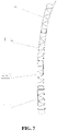
- FIG. 7 is a schematic cross sectional structural view of the side wall.
- the double-layer pultruded profile of each side roof 3 includes a first side roof profile 3-1 and a second side roof profile 3-2, and the first side roof profile 3-1 and the second side roof profile 3-2 are connected through a plug joint with self-expanding adhesive, the chambers in the profiles are substantially designed into trapezoidal chambers and triangular chambers according to requirements of strength and mounting interface, and the plug joint is positioned in a low stress area of the structure.
- Both sides of the side roof 3 are designed as lapping joints, a position and a structure of the upper lapping joint match with that of the lapping joint of the roof 1, which meets the assembly and mounting requirements of the roof and an air conditioner seat.
- a position of the lower lapping joint is the same with a position of a window opening, and a structure of which meets the requirements of mounting and sealing of a glass.
- Corresponding functional materials may be filled in the chambers of the structure of the side roofs 3 according to the requirements of heat insulation, vibration isolation and noise reduction of the structure, so as to improve the functional index of the structure.
- Each side roof 4 is bonded by four composite material pultruded profiles through two plug joints and one lapping joint with self-expanding adhesive, the chambers in the profiles are substantially designed into triangular chambers and trapezoidal chambers according to requirements of strength and mounting interface, and the plug joints are positioned in a low stress area of the structure.
- each side wall 4 includes a first side wall profile 4-1, a second side wall profile 4-2, a third side wall profile 4-3 and a fourth side wall profile 4-4, the first side wall profile 4-1 is connected to the second side wall profile 4-2 through a plug joint, the second side wall profile 4-2 is connected to the third side wall profile 4-3 through a lapping joint, and the third side wall profile 4-3 is connected to the fourth side wall profile 4-4 through a plug joint.
- An upper end of the side wall 4 is designed as a lapping joint, and the position and the structure of which are matched with the lapping joint of the side roof 3 so as to meet the assembly requirement of the side roof 3.
- corresponding functional materials may be filled in the chambers of the structure of the side walls according to the requirements of heat insulation, vibration isolation and noise reduction of the structure, so as to improve the functional index of the structure.
- FIG. 8 is a cross sectional view of the splicing-type vehicle body shown in FIG. 1 taken along B-B.
- a position of the lapping joint on the upper edge of the side roof 3 is the same with a position of a roof air conditioner seat
- the lapping joint of the side roof 3 has the sane structure with a structure of a roof equipment mounting seat interface
- a position of the lapping joint on the lower edge of the side roof 3 is the same with a position of an upper edge of the window opening.
- connections between two sides of the roof 1 and the side roofs are designed as lapping joints, so as to meet the mounting requirements of assembling the roof to the vehicle body, positions of the lapping joints are the same with the positions of the roof air conditioner seat, the lapping joints have the same structure with the roof equipment mounting seat interface such as the air conditioner, so as to meet the technical requirements of layout and position adjustment of the air conditioner and the technical requirement of sealing of the vehicle body.
- FIG. 5 is a schematic partial enlarged view of Portion II shown in FIG. 4 .
- the plug joint between the first roof profile 1-1 and the second roof profile 1-2 is composed of a male plug 1-4 and a female plug 1-5
- the female plug 1-5 is formed on a left edge of the first roof profile 1-1
- the male plug 1-4 is formed on a right edge of the second roof profile 1-2
- the female plug 1-5 has a socket outer edge and a socket inner edge extending from the outer plate and the inner plate, respectively
- a step configured to be matched with the socket outer edge is formed on the outer plate of the male plug 1-4
- a step configured to be matched with the socket inner edge is formed on the inner plate of the male plug 1-4, so as to ensure a smooth transition between the inner surface and the outer surface of the two profiles after plug.
- multiple slots 1-6 or recesses parallel along an axial direction are formed on an end surface, the outer plate and an outer surface of the inner plate of the male plug 1-4, respectively.
- multiple slots 1-6 or recesses can be formed on an end surface, the outer plate and an inner surface of the inner plate of the female plug 1-5, respectively.
- the plug joints of the side roofs 3, the side walls 4 and the underframe 2 are similar with the plug joint of the roof 1, which will not be illustrated one by one here.
- FIG. 9 is a schematic partial enlarged view of Portion III shown in FIG. 8 .
- the lapping joint between the side roof 3 and the side wall 4 includes a first lapping end 3-3 formed on the lower edge of the second side roof profile 3-2 and a second lapping end 4-5 formed on the upper edge of the first side roof profile 4-1, an outer side of the first lapping end 3-3 is provided with a first lapping edge extending from the outer plate, an inner side of the second lapping end 4-5 is provided with a second lapping edge extending from the inner plate, a step configured to be matched with the first lapping edge is formed on an outer side of the second lapping end, and a step configured to be matched with the second lapping edge is formed on an inner side of the first lapping end.
- multiple slots 1-6 or multiple recesses parallel along the axial direction are formed on an end surface and an inner side surface of the first lapping end 3-3 and an inner surface of the first lapping edge.
- multiple slots 1-6 or multiple recesses can be formed on an end surface and an inner side surface of the second lapping end 4-5 and an inner surface of the second lapping edge.
- FIG. 3 is a schematic partial enlarged view of Portion I shown in FIG. 2 .
- the push-on joint between the side wall 4 and the underframe 2 is mainly composed of a push-on slot formed on an upper surface of the edge of the underframe 2 and a push-on connector 5-1 formed on the lower edge of the side wall connector 5,
- the side wall connector 5 is also a double-layer pultruded profile made of carbon fiber composite material, a top of the side wall connector 5 is connected to the side wall 4 through the plug joint, an interior of the side wall connector 5 is in the form of the combination of triangular chambers and rectangular chambers, so as to meet the requirements of connection structure strength at the root of the side wall and the requirements of the profile pultrusion process.
- the push-on slot of the underframe 2 includes a first push-on plate 2-8 and a second push-on plate 2-9, the first push-on plate 2-8 is located on an outer side, the second push-on plate 2-9 is located on an inner side, and a distance between the first push-on plate 2-8 and the second push-on plate 2-9 gradually increases from top to bottom, and a trapezoidal push-on slot is formed between the first push-on plate 2-8 and the second push-on plate 2-9; the push-on connector 5-1 of the side wall connector 5 has a trapezoidal cross section which is pushed into the push-on slot from an end.
- multiple slots 1-6 or multiple recesses parallel along the axial direction are formed on an inner surface of the push-on slot or an outer surface of the push-on connector 5-1.
- the cross section of the side wall connector 5 has the trapezoidal structure, which cannot be plugged and connected with the push-on slot of the underframe 2, the whole side wall connector 5 can be pushed from the end along the axial direction with a push tool and then a bonding process is carried out during assembly.
- FIG. 10 is a cross sectional view of the splicing-type vehicle body shown in FIG. 1 taken along C-C; and FIG. 11 is a schematic cross sectional structural view of the underframe at a vehicle door.
- the second side roof profile 3-2 of the side roof 3 is provided with a mounting rib plate 8 on an upper edge of the vehicle door according to the requirements for assembling a vehicle door, so as to meet the requirements of mounting and sealing of the vehicle door.
- the two lapping joints of the side walls 4 are at the same level with a vehicle window, and the structure of which meets the requirement of mounting a vehicle window glass.
- the two side wall profiles (that is, the second side wall profile 4-2 and the third wall profile 4-3) are cut at the vehicle window, and a cutting size is the same with a length of the vehicle window, which can meet technical the technical requirements of window opening, reduce the processing process of the product opening, and improve the production efficiency and quality.
- the underframe 2 is bonded by seven composite material pultruded profiles through six plug joints with self-expanding adhesive, the chambers in the profiles are substantially designed into triangular chambers and trapezoidal chambers according to requirements of strength and mounting interface, and the plug joints are positioned in a low stress area of the structure.
- the double-layer pultruded profile of the underframe 2 includes a first underframe profile 2-1 in the middle, a second underframe profile 2-2, a third underframe profile 2-3, a fourth underframe profile 2-4, a fifth underframe profile 2-5, a sixth underframe profile 2-6 and a seventh underframe profile 2-7 which are systematically arranged at both sides, the second underframe profile 2-2.
- These seven double-layer pultruded profiles are connected through six plug joints, the second underframe profile 2-2 and the seventh underframe profile 2-7 are further connected to the side walls 4 through the push-on connectors 5-1 of the side wall connectors 5. If the side wall connectors 5-1 are regarded as a composite part of the underframe 2, it equals that the underframe 2 has nine composite material pultruded profiles.
- a height of the first underframe profile 2-1 is greater than the second underframe profile 2-2 and the fifth underframe profile 2-5 on the two sides of the first underframe profile 2-1, and bending portions extending obliquely upward to be transitionally connected to the first underframe profile 2-1 are provided on the second underframe profile 2-2 and the fifth underframe profile 2-5, respectively.
- a thickness of an inner side is greater than that of an outer side of the second underframe profile 2-2
- a structure of the fifth underframe profile 2-5 is mirror-symmetrical with that of the second underframe profile 2-2.
- a thickness of an outer side is greater than that of an inner side of the fourth underframe profile 2-4
- a structure of the seventh underframe profile 2-7 is mirror-symmetrical with that of the fourth underframe profile 2-4.
- Upper portions of the fourth underframe profile 2-4 and the seventh underframe profile 2-7 are designed as lapping joints. Besides a structure of a socket can meet the mounting requirement of the push-on joints, a turning edge of the socket can be further removed by machining so as to form a platform step 2-10 at the position of the vehicle body for mounting vehicle doors in order to meet the requirements of mounting and sealing of the vehicle door mechanism.
- corresponding functional materials may be filled in the chambers of the structure of the underframe 2 according to the requirements of heat insulation, vibration isolation and noise reduction of the structure to improve the functional index of the structure, so that the functional effect of the underframe 2 is better than a sandwich structure with a single structure.
- the above composite material vehicle structure mainly includes parts of the roof 1, the side roofs 3, the side walls 4 and the underframe 2, these parts can be integrally assembled into a whole vehicle structure after being separately assembled. Instead, the roof 1, the side roofs 3 and the side walls 4 can be assembled to become parts of the vehicle, and then assembled with the underframe 2 to form the whole vehicle structure.
- the assembly and manufacturing method of the vehicle body are flexible, and the assembly method can be flexibly selected according to the order quantity, assembly equipment, construction site and other conditions.
- each side roof 3 are connected to the edge of the roof 1 and the upper edge of the side wall, respectively, through the lapping joints in opposite lapping directions, and the connection strength can be further improved by providing the lapping joints in opposite lapping directions.
- the double-layer pultruded profile may be a metal profile, such as an aluminum alloy profile. If the double-layer pultruded profile is the aluminum alloy profile, adjacent double-layer pultruded profile are connected by welding at the plug joints, the lapping joints and the push-on joints according to the material property, and other structures are substantially the same with the above embodiments, which can refer to the above embodiments.
- the inner chambers of the roof 1, the side roofs 3, the side walls 4 and the underframe 2 are designed into other combinations of the triangular chambers, the trapezoidal chambers and the rectangular chambers, or the number of splicing profiles of the roof 1, the side roofs 3, the side walls 4 and the underframe 2 is further increased or decreased. Since there are a lot of possible implementations, no more examples are taken and illustrated here.
- the assembly method can be flexibly adjusted according to the actual production resources of the product.
- a rail vehicle is provided according to the present application, which includes a vehicle body, and a vehicle window, a vehicle door and a roof air conditioner arranged in the vehicle body.
- the vehicle body is the splicing-type vehicle body as described above, and other structures of the rail vehicle can refer to the conventional technology, and will not be repeated herein.
Landscapes
- Engineering & Computer Science (AREA)
- Mechanical Engineering (AREA)
- Life Sciences & Earth Sciences (AREA)
- Wood Science & Technology (AREA)
- Body Structure For Vehicles (AREA)
- Fittings On The Vehicle Exterior For Carrying Loads, And Devices For Holding Or Mounting Articles (AREA)
Abstract
Description
- This application claims the benefit of priorities to the following two Chinese patent applications, both of which are incorporated herein by reference,
- 1)
Chinese Patent Application No. 202010003050.0, titled "ASSEMBLY-TYPE CAR BODY AND RAIL VEHICLE", filed with the China National Intellectual Property Administration on January 2, 2020 - 2)
Chinese Patent Application No. 202020002975.9, titled "ASSEMBLY-TYPE CAR BODY AND RAIL VEHICLE", filed with the China National Intellectual Property Administration on January 2, 2020 - The present application relates to the technical field of rail vehicles, and in particular to a splicing-type vehicle body of a rail vehicle. The present application further relates to a rail vehicle with the splicing-type vehicle body.
- With the increasing speed of a rail vehicle, higher requirements have been put forward for the structural strength, stiffness and lightweight design of a vehicle body of the rail vehicle.
- A metal vehicle body of the existing rail vehicle is generally assembled by welding metal materials such as carbon steel, stainless steel, and aluminum alloy, which has disadvantages of large self-weight, low strength and easy corrosion compared with a composite material vehicle body. The composite material vehicle body mainly has a plate-beam assembly structure or a single-layer profile splicing structure. The product has large number of structural sections, the assembly workload is large, the sections are connected by rivets or bonded rivets, there are many connecting holes with large processing capacity of rivet holes and easy rain leakage; a large number of metal connectors are used in the structures of the vehicle body, which has poor weight reduction effect and low production efficiency; panels of the vehicle body are mainly in sandwich structures, a core material is prone to quality defects during molding, and the sound insulation effect is poor.
- It can be seen that the vehicle body of the rail vehicle has disadvantages of complex structure, large overall weight, low production efficiency, etc., which cannot meet the higher technical requirements of the vehicle for lightweight and corrosion resistance, and needs to be further improved.
- An object according to the present application is to provide a splicing-type vehicle body. Under the same strength condition, the vehicle body has advantages of high stiffness, light self-weight and high production efficiency, which can meet the load requirements of complex working conditions such as air tightness load and torsional load of the vehicle body of the rail vehicle.
- Another object is to provide a rail vehicle with the splicing-type vehicle body.
- In order to achieve the above object, a splicing-type vehicle body is provided according to the present application, which includes a roof, a underframe, side roofs and side walls located on two sides; an upper edge of each side roof is connected to an edge of the roof, an upper edge of each side wall is connected to a lower edge of the side roof, a lower edge of each side wall is connected to an edge of the underframe; the roof, the underframe, the side roofs and the side walls are respectively formed by splicing double-layer pultruded profiles with different shapes, each double-layer pultruded profile includes an outer plate, an inner plate and chambers in an interlayer between the outer plate and the inner plate and separated by rib plates; the upper edge and the lower edge of each side roof are respectively connected to the edge of the roof and the upper edge of the side wall through lapping joints, the lower edge of each side wall is connected to the edge of the underframe through a side wall connector; the side wall connector is a single double-layer pultruded profile, an upper edge of the side wall connector is connected to the lower edge of the side wall through a plug joint, and a lower edge of the side wall connector is connected to the edge of the underframe through a push-on joint.
- Preferably, each lapping joint comprises a first lapping end and a second lapping end respectively formed on edges of two connected double-layer pultruded profiles, an outer side of the first lapping end is provided with a first lapping edge extending from the outer plate, an inner side of the second lapping end is provided with a second lapping edge extending from the inner plate, a step matched with the first lapping edge is formed on an outer side of the second lapping end, and a step matched with the second lapping edge is formed on an inner side of the first lapping end.
- Preferably, a slot or a recess is formed on an end surface and an inner side surface of the first lapping end and an inner surface of the first lapping edge, respectively; or a slot or a recess is formed on an end surface and an inner side surface of the second lapping end and an inner surface of the second lapping edge, respectively.
- Preferably, each plug joint includes a male plug and a female plug respectively formed on edges of two connected double-layer pultruded profiles, the female plug has a socket outer edge and a socket inner edge respectively extending from the outer plate and the inner plate, a step configure to be matched with the socket outer edge is formed on the outer plate of the male plug, and a step configure to be matched with the socket inner edge is formed on the inner plate of the male plug.
- Preferably, a slot or a recess is formed on an end surface, the outer plate and an outer surface of the inner plate of the male plug; or, a slot or a recess is formed on an end surface, the outer plate and an inner surface of the inner plate of the female plug.
- Preferably, each push-on joint includes a push-on slot formed on an upper surface of the edge of the underframe and a push-on connector formed on the lower edge of the side wall connector; the push-on slot includes a first push-on plate and a second push-on plate, the first push-on plate is located on an outer side, the second push-on plate is located on an inner side, a distance between the first push-on plate and the second push-on plate gradually increases from top to bottom, and a trapezoidal push-on slot is formed between the first push-on plate and the second push-on plate; the push-on connector of the side wall connector has a trapezoidal cross section so as to be pushed into the push-on slot from an end.
- Preferably, a slot or a recess is formed in an inner surface of the push-on slot or an outer surface of the push-on connector.
- Preferably, the upper edge and the lower edge of each side roof are respectively connected to the edge of the roof and the upper edge of the side wall through the lapping joints in opposite lapping directions.
- Preferably, a distance between the outer plate and the inner plate of the double-layer pultruded profile of each side roof in a cross section gradually increases and then decreases from the upper edge to the lower edge; the distance between the outer plate and the inner plate of the double-layer pultruded profile of each side wall in a cross section gradually decreases and then increases from the upper edge to the lower edge.
- Preferably, the splicing-type vehicle body further includes an air duct profile connected below the roof, and the air duct profile is configured to form a sealed roof ventilation air duct.
- Preferably, an axial passage with an upward opening is defined inside the roof ventilation air duct, and the axial passage and a lower surface of the double-layer pultruded profile of the roof form the roof ventilation air duct.
- Preferably, the axial passage includes a main passage located at the center and sub passages located on two sides of the main passage.
- Preferably, the sub passages includes a first sub passage located outside the main passage and a second sub passage located outside the first sub passage; the main passage is substantially rectangular, the first sub passage is substantially trapezoidal, and the second sub passage is substantially triangular.
- Preferably, the axial passage of the air duct profile is formed by providing a vertical partition plate, a connecting portion in a bending shape is respectively provided on an upper edge of the partition plate and upper edges of two sides of the air duct profile, and the connecting portions abut against a lower surface of the roof and are bonded riveted with the lower surface of the roof.
- Preferably, the air duct profile includes a left profile and a right profile which are symmetrical and a connecting plate in the middle, the connecting plate forms a bottom of the main passage, and a left edge and a right edge of the connecting plate are respectively stacked and connected to extension edges at bottoms of the left profile and the right profile.
- Preferably, the double-layer pultruded profile of the roof includes a first roof profile in the middle and a second roof profile and a third roof profile which are symmetrical, and the first roof profile is respectively connected to the second roof profile and the third roof profile through plug joints.
- Preferably, the double-layer pultruded profile of each side roof includes a first side roof profile and a second side roof profile, and the first side roof profile and the second side roof profile are connected through a plug joint.
- Preferably, a position of the lapping joint on the upper edge of the side roof is the same with a position of a roof conditioner mounting seat, the lapping joint of the side roof has the same structure with that of a roof equipment mounting seat interface; a position of the lapping joint on the lower edge of the side roof is the same with a position of an upper edge of a window opening.
- Preferably, the side roof is provided with a mounting rib plate for assembling a vehicle door on an upper edge of the vehicle door.
- Preferably, the double-layer pultruded profile of each side wall includes a first side wall profile, a second side wall profile, a third side wall profile and a fourth side wall profile, the first side wall profile is connected to the second side wall profile through a plug joint, the second side wall profile is connected to the third side wall profile through a lapping joint, and the third side wall profile is connected to the fourth side wall profile through a plug joint.
- Preferably, the lapping joint between the second side wall profile and the third side wall profile is at the same level with a lower edge of a vehicle window, the first side wall profile and the second side wall profile are cut at the vehicle window, a cutting size of is the same with a length of the vehicle window, to form a window opening.
- Preferably, the double-layer pultruded profile of the underframe includes a first underframe profile in the middle, a second underframe profile, a third underframe profile, a fourth underframe profile, a fifth underframe profile, a sixth underframe profile and a seventh underframe, the second underframe profile, the third underframe profile and the fourth underframe profile are symmetrical with the fifth underframe profile, the sixth underframe profile and the seventh underframe profile on two sides of the first underframe profile, and the first underframe profile, the second underframe profile, the third underframe profile, the fourth underframe profile, the fifth underframe profile, the sixth underframe profile and the seventh underframe profile are connected through six plug joints.
- Preferably, a height of the first underframe profile is higher than the second underframe profile and the fifth underframe profile on the two sides of the first underframe profile, and a bending portion extending obliquely upward to be transitionally connected to the first underframe profile is respectively provided on the second underframe profile and the fifth underframe profile.
- Preferably, a platform step is formed at a connection between each side wall and the underframe by removing a flange of a socket to mount a vehicle door mechanism.
- Preferably, the chambers of each double-layer pultruded profile include a triangular chamber, a trapezoidal chamber, a rectangular chamber and a combination of the triangular chamber, the trapezoidal chamber and the rectangular chamber.
- Preferably, the chambers of each double-layer pultruded profile of the roof, the underframe, the side roofs or the side walls are filled with thermal insulation material, vibration insulation material or noise reduction material.
- Preferably, each double-layer pultruded profile is made of a carbon fiber composite material, and adjacent double-layer pultruded profiles are connected at a joint through adhesive; or,
each double-layer pultruded profile is made of an aluminum alloy material, and adjacent double-layer pultruded profiles are connected at a joint by welding. - In order to achieve the above object, a rail vehicle is provided according to the present application, which includes a vehicle body, a vehicle window, a vehicle door and a roof air conditioner which are arranged on the vehicle body, and the vehicle body is the splicing-type vehicle body according to any one of the above.
- The vehicle body provided according to the present application is composed of the roof, the underframe, the side roofs and the side walls on the two sides, and the side wall connectors, which are splicing assembled by means of lapping, plugging and pushing-on through the lapping joints, the plug joints and the push-on joints so as to form a barrel-shaped vehicle body structure, and each composite part is the double-layer pultruded profile, the multi-chamber profile has the characteristics of high strength, high stiffness and small weight of the multi-chamber profiles, so that the vehicle body structure has the characteristics of large stiffness, small self-weight and high production efficiency under the same strength condition, which can meet the load requirements of complex working conditions such as air tightness load and torsional load of the vehicle body of the rail vehicle, and well solves the problems of large self-weight, low strength and easy corrosion of the metal vehicle body of the existing rail vehicle can be solve. Meanwhile, the problems of large number of sections, poor effects of sealing and weight reduction, and low production efficiency of the existing composite material vehicle body can be solved. Furthermore, the assembly method can be flexibly adjusted according to the actual production resources of the product.
-
-
FIG. 1 is a side view of a splicing-type vehicle body according to an embodiment of the present application; -
FIG. 2 is a cross sectional view of the splicing-type vehicle body shown inFIG. 1 taken along A-A; -
FIG. 3 is a schematic partial enlarged view of portion I shown inFIG. 2 ; -
FIG. 4 is a schematic cross sectional structural view of a roof ventilation air duct formed by a roof and an air duct profile; -
FIG. 5 is a schematic partial enlarged view of portion II shown inFIG. 4 ; -
FIG. 6 is a schematic cross sectional structural view of a side roof; -
FIG. 7 is a schematic cross sectional structural view of a side wall; -
FIG. 8 is a cross sectional view of the splicing-type vehicle body shown inFIG. 1 taken along B-B; -
FIG. 9 is a schematic partial enlarged view of portion III shown inFIG. 8 ; -
FIG. 10 is a cross sectional view of the splicing-type vehicle body shown inFIG. 1 taken along C-C; and -
FIG. 11 is a schematic cross sectional structural view of an underframe at a vehicle door. - Reference numerals are as follows:
1 roof; 1-1 first roof profile; 1-2 second roof profile; 1-3 third roof profile; 1-4 male plug; 1-5 female plug; 1-6 slot; 2 underframe; 2-1 first underframe profile; 2-2 second underframe profile; 2-3 third underframe profile; 2-4 fourth underframe profile; 2-5 fifth underframe profile; 2-6 sixth underframe profile; 2-7 seventh underframe profile; 2-8 first push-on plate; 2-9 second push-on plate; 2-10 platform step; 3 side roof; 3-1 first side roof profile; 3-2 second side roof profile; 3-3 first lapping end; 4 side wall; 4-1 first side wall profile; 4-2 second side wall profile; 4-3 third side wall profile; 4-4 fourth side wall profile; 4-5 second lapping end; 5 side wall connector; 5-1 push-on connector; 6 air duct profile; 6-1 connecting plate; 6-2 left profile; 6-3 right profile; 6-4 partition plate; 6-5 connecting portion; 6-6 bearing portion; 7 roof ventilation air duct; 8 vehicle door mounting rib plate; 9 air conditioner mounting seat interface; 10 vehicle window mounting rib plate; 11 vehicle body. - In order to enable those skilled in the art to better understand the technical solutions of the present application, the present application will be further described in detail with reference to the drawings and specific embodiments.
- Herein, terms such as "up, down, left, right" are established based on the positional relationship shown in the accompanying drawings, and the corresponding positional relationship may also change according to the different accompanying drawings. Therefore, it should not be construed as an absolute limitation on the scope of the protection. In addition, relational terms such as "first" and "second" are only used to distinguish one element from another with the same name, and do not necessarily require or imply any such actual relationship or order between these elements.
- Referring to
FIG. 1 and FIG. 2, FIG. 1 is a side view of a splicing-type vehicle body according to an embodiment of the present application; andFIG. 2 is a cross sectional view of the splicing-type vehicle body shown inFIG. 1 taken along A-A. - A carbon fiber composite material has excellent comprehensive properties of lightweight, high strength and high weather resistance, which becomes the preferred material to solve the problems of lightweight of a rail vehicle.
- As shown in the figures, in a specific embodiment, a splicing-type vehicle body 11 provided according to the present application is assembled mainly in splicing type by double-layer pultruded profiles made of carbon fiber composite material, the adjacent double-layer pultruded profiles are connected at a joint through adhesive to realize seamless connection of each module. The double-layer pultruded profiles are produced by pultrusion technology, and a main cross section of the vehicle body includes composite material double-layer pultruded profiles, sixteen plug joints, six lapping joints and two push-on joints which are bond to those profiles through self-expanding adhesive so that a main structure of a barrel-shaped composite material vehicle body is assembled The vehicle with the structure has excellent strength, stiffness and air tightness, which can meet the load requirements of complex working conditions such as air tightness load and torsional load of the vehicle body of the rail vehicle. In addition, under the same strength condition, the self-weight is small, the cross section of the vehicle body is simple, the structural sections are less, the assembly workload is small, the profiles of the vehicle body can be assembled and connected quickly, the production efficiency of the vehicle body is high and the quality is stable.
- Specifically, the vehicle body 11 is substantially composed of a roof 1, a
underframe 2,side roofs 3 andside walls 4 located on two sides, an upper edge of eachside roof 3 is connected to an edge of the roof 1, an upper edge of eachside wall 4 is connected to a lower edge of theside roof 3, and a lower edge of eachside wall 4 is connected to an edge of theunderframe 2. - The roof 1, the
underframe 2, theside roofs 3 and theside walls 4 are respectively formed by splicing double-layer pultruded profiles with different shapes, each double-layer pultruded profile includes an outer plate, an inner plate and chambers in an interlayer between the outer plate and the inner plate and separated by rib plates; the upper edge and the lower edge of eachside roof 3 are respectively connected to the edge of the roof 1 and the upper edge of theside wall 4 through lapping joints. The lower edge of eachside wall 3 is connected to the edge of theunderframe 2 through aside wall connector 5, which is a single double-layer pultruded profile, and an upper edge of theside wall connector 5 is connected to the lower edge of theside wall 4 through a plug joint, and a lower edge of theside wall connector 5 is connected to the edge of theunderframe 2 through a push-on joint. - According to the different technical requirements such as strength, stiffness, tightness and lightweight of various parts of the vehicle body structure, the profiles of the vehicle body have a structure with a variable cross section, a distance between the outer plate and the inner plate of the double-layer pultruded profile of each
side roof 3 gradually increases and then gradually decreases from the upper edge to the lower edge, a distance between the outer plate and the inner plate of the double-layer pultruded profile of eachside wall 4 gradually decreases and then gradually increases from the upper edge to the lower edge, the chambers of the profiles are triangular chambers, trapezoidal chambers, rectangular chambers and various combinations of the triangular chambers, the trapezoidal chambers and the rectangular chambers. - Referring to
FIG. 4, FIG. 4 is a schematic cross sectional structural view of a roof ventilation air duct formed by a roof and an air duct profile. - As shown in the figure, the double-layer pultruded profile of the roof 1 mainly includes a first roof profile 1-1 in the middle and a second roof profile 1-2 and a third roof profile 1-3 which are symmetrical, where the first roof profile 1-1 is respectively connected to the second roof profile 1-2 and the third roof profile 1-3 through plug joints.
- The three roof profiles are bonded through two plug joints with self-expanding adhesive, the inner chambers of the profiles are substantially designed into trapezoidal chambers according to requirements of strength and mounting interface in combination with the requirement of weight reduction, and the plug joints are positioned in a low stress area of the roof structure.
- An
air duct profile 6 is provided below the roof 1, an axial passage with an upward opening is defined inside theair duct profile 6, and the axial passage forms a roof ventilation air duct 7 with a lower surface of the double-layer pultruded profile of the roof 1. - The
air duct profile 6 is formed by bonding three profiles, which are a left profile 6-2 and a right profile 6-3 of being symmetrical and a connecting plate 6-1 in the middle, respectively, the axial passage of theair duct profile 6 is divided into a main passage located at the center and sub passages located on two sides of the main passage, and a left edge and a right edge of the connecting plate 6-1 are stacked and connected to extension edges at bottoms of the left profile 6-2 and the right profile 6-3, respectively, to form a bottom of the main passage. The main passage is substantially rectangular. The sub passages include a first sub passage located outside the main passage and a second sub passage located outside the first sub passage, the first sub passage is substantially trapezoidal, and the second sub passage is substantially triangular. - The axial passage of the
air duct profile 6 is formed by providing a vertical partition plate 6-4, a connecting portion in a bending shape is provided on an upper edge of the partition plate 6-4 and upper edges of two sides of theair duct profile 6, respectively, and the connecting portions 6-5 are attached to a lower surface of the roof 1 and are connected with the lower surface of the roof 1 by being bonded riveted. - A lower surface of the
air duct profile 6 is symmetrically provided with two sets of bearing portions 6-6 in right-angle shape, one set of bearing portions 6-6 is bent inward, the other set of bending portions 6-6 is bent outward, and an interval between the bearing portions 6-6 bent inward is greater than that of the bending portions 6-6 bent outward. - The air duct structure and the roof form a sealed passage chamber after being bonded riveted with each other, which can meet the requirements of the vehicle ventilation and equipment pipeline passage. After the roof ventilation air duct 7 and the roof 1 are fixed, they can be used as an integral structure to be jointly involved in the loading of the vehicle body, which improves the strength, stiffness of the vehicle body, and meets the technical requirements of strength, stiffness and lightweight of the vehicle body.
- Corresponding functional materials may be filled in the chambers of the structure of the roof according to the requirements of heat insulation, vibration isolation and noise reduction of the structure, so as to improve the functional index of the structure.
- Referring to
FIG. 6 andFIG. 7 ,FIG. 6 is a schematic cross sectional structural view of the side roof; andFIG. 7 is a schematic cross sectional structural view of the side wall. - As shown in the figures, the double-layer pultruded profile of each
side roof 3 includes a first side roof profile 3-1 and a second side roof profile 3-2, and the first side roof profile 3-1 and the second side roof profile 3-2 are connected through a plug joint with self-expanding adhesive, the chambers in the profiles are substantially designed into trapezoidal chambers and triangular chambers according to requirements of strength and mounting interface, and the plug joint is positioned in a low stress area of the structure. - Both sides of the
side roof 3 are designed as lapping joints, a position and a structure of the upper lapping joint match with that of the lapping joint of the roof 1, which meets the assembly and mounting requirements of the roof and an air conditioner seat. A position of the lower lapping joint is the same with a position of a window opening, and a structure of which meets the requirements of mounting and sealing of a glass. - Corresponding functional materials may be filled in the chambers of the structure of the
side roofs 3 according to the requirements of heat insulation, vibration isolation and noise reduction of the structure, so as to improve the functional index of the structure. - Each
side roof 4 is bonded by four composite material pultruded profiles through two plug joints and one lapping joint with self-expanding adhesive, the chambers in the profiles are substantially designed into triangular chambers and trapezoidal chambers according to requirements of strength and mounting interface, and the plug joints are positioned in a low stress area of the structure. - The double-layer pultruded profile of each
side wall 4 includes a first side wall profile 4-1, a second side wall profile 4-2, a third side wall profile 4-3 and a fourth side wall profile 4-4, the first side wall profile 4-1 is connected to the second side wall profile 4-2 through a plug joint, the second side wall profile 4-2 is connected to the third side wall profile 4-3 through a lapping joint, and the third side wall profile 4-3 is connected to the fourth side wall profile 4-4 through a plug joint. - An upper end of the
side wall 4 is designed as a lapping joint, and the position and the structure of which are matched with the lapping joint of theside roof 3 so as to meet the assembly requirement of theside roof 3. - Similarly, corresponding functional materials may be filled in the chambers of the structure of the side walls according to the requirements of heat insulation, vibration isolation and noise reduction of the structure, so as to improve the functional index of the structure.
- Referring to
FIG. 8, FIG. 8 is a cross sectional view of the splicing-type vehicle body shown inFIG. 1 taken along B-B. - As shown in the figure, a position of the lapping joint on the upper edge of the
side roof 3 is the same with a position of a roof air conditioner seat, the lapping joint of theside roof 3 has the sane structure with a structure of a roof equipment mounting seat interface, and a position of the lapping joint on the lower edge of theside roof 3 is the same with a position of an upper edge of the window opening. - Connections between two sides of the roof 1 and the side roofs are designed as lapping joints, so as to meet the mounting requirements of assembling the roof to the vehicle body, positions of the lapping joints are the same with the positions of the roof air conditioner seat, the lapping joints have the same structure with the roof equipment mounting seat interface such as the air conditioner, so as to meet the technical requirements of layout and position adjustment of the air conditioner and the technical requirement of sealing of the vehicle body.
- The structures of the plug joint, lapping joint and push-on joint are further described in detail below.
- Referring to
FIG. 5, FIG. 5 is a schematic partial enlarged view of Portion II shown inFIG. 4 . - As shown in the figure, the plug joint between the first roof profile 1-1 and the second roof profile 1-2 is composed of a male plug 1-4 and a female plug 1-5, the female plug 1-5 is formed on a left edge of the first roof profile 1-1, the male plug 1-4 is formed on a right edge of the second roof profile 1-2, the female plug 1-5 has a socket outer edge and a socket inner edge extending from the outer plate and the inner plate, respectively, a step configured to be matched with the socket outer edge is formed on the outer plate of the male plug 1-4, and a step configured to be matched with the socket inner edge is formed on the inner plate of the male plug 1-4, so as to ensure a smooth transition between the inner surface and the outer surface of the two profiles after plug.
- In order to further improve the reliability of the connection, multiple slots 1-6 or recesses parallel along an axial direction are formed on an end surface, the outer plate and an outer surface of the inner plate of the male plug 1-4, respectively. Instead, multiple slots 1-6 or recesses can be formed on an end surface, the outer plate and an inner surface of the inner plate of the female plug 1-5, respectively.
- The plug joints of the
side roofs 3, theside walls 4 and theunderframe 2 are similar with the plug joint of the roof 1, which will not be illustrated one by one here. - Referring to
FIG. 9, FIG. 9 is a schematic partial enlarged view of Portion III shown inFIG. 8 . - As shown in the figure, the lapping joint between the
side roof 3 and theside wall 4 includes a first lapping end 3-3 formed on the lower edge of the second side roof profile 3-2 and a second lapping end 4-5 formed on the upper edge of the first side roof profile 4-1, an outer side of the first lapping end 3-3 is provided with a first lapping edge extending from the outer plate, an inner side of the second lapping end 4-5 is provided with a second lapping edge extending from the inner plate, a step configured to be matched with the first lapping edge is formed on an outer side of the second lapping end, and a step configured to be matched with the second lapping edge is formed on an inner side of the first lapping end. - In order to further improve the reliability of the connection, multiple slots 1-6 or multiple recesses parallel along the axial direction are formed on an end surface and an inner side surface of the first lapping end 3-3 and an inner surface of the first lapping edge. Instead, multiple slots 1-6 or multiple recesses can be formed on an end surface and an inner side surface of the second lapping end 4-5 and an inner surface of the second lapping edge.
- The structures of the lapping joints between the
side roofs 3 and the roof 1 and the lapping joints of theside walls 4 are similar to those of the above lapping joints, which will not be illustrated one by one here. - Referring to
FIG. 3, FIG. 3 is a schematic partial enlarged view of Portion I shown inFIG. 2 . - As shown in the figure, the push-on joint between the
side wall 4 and theunderframe 2 is mainly composed of a push-on slot formed on an upper surface of the edge of theunderframe 2 and a push-on connector 5-1 formed on the lower edge of theside wall connector 5, theside wall connector 5 is also a double-layer pultruded profile made of carbon fiber composite material, a top of theside wall connector 5 is connected to theside wall 4 through the plug joint, an interior of theside wall connector 5 is in the form of the combination of triangular chambers and rectangular chambers, so as to meet the requirements of connection structure strength at the root of the side wall and the requirements of the profile pultrusion process. - The push-on slot of the
underframe 2 includes a first push-on plate 2-8 and a second push-on plate 2-9, the first push-on plate 2-8 is located on an outer side, the second push-on plate 2-9 is located on an inner side, and a distance between the first push-on plate 2-8 and the second push-on plate 2-9 gradually increases from top to bottom, and a trapezoidal push-on slot is formed between the first push-on plate 2-8 and the second push-on plate 2-9; the push-on connector 5-1 of theside wall connector 5 has a trapezoidal cross section which is pushed into the push-on slot from an end. - In order to further improve the reliability of the connection, multiple slots 1-6 or multiple recesses parallel along the axial direction are formed on an inner surface of the push-on slot or an outer surface of the push-on connector 5-1.
- Since the cross section of the
side wall connector 5 has the trapezoidal structure, which cannot be plugged and connected with the push-on slot of theunderframe 2, the wholeside wall connector 5 can be pushed from the end along the axial direction with a push tool and then a bonding process is carried out during assembly. - Referring to
FIG. 10 and FIG. 11, FIG. 10 is a cross sectional view of the splicing-type vehicle body shown inFIG. 1 taken along C-C; andFIG. 11 is a schematic cross sectional structural view of the underframe at a vehicle door. - As shown in the figures, the second side roof profile 3-2 of the
side roof 3 is provided with a mounting rib plate 8 on an upper edge of the vehicle door according to the requirements for assembling a vehicle door, so as to meet the requirements of mounting and sealing of the vehicle door. - The two lapping joints of the
side walls 4 are at the same level with a vehicle window, and the structure of which meets the requirement of mounting a vehicle window glass. The two side wall profiles (that is, the second side wall profile 4-2 and the third wall profile 4-3) are cut at the vehicle window, and a cutting size is the same with a length of the vehicle window, which can meet technical the technical requirements of window opening, reduce the processing process of the product opening, and improve the production efficiency and quality. - The
underframe 2 is bonded by seven composite material pultruded profiles through six plug joints with self-expanding adhesive, the chambers in the profiles are substantially designed into triangular chambers and trapezoidal chambers according to requirements of strength and mounting interface, and the plug joints are positioned in a low stress area of the structure. - Specifically, the double-layer pultruded profile of the
underframe 2 includes a first underframe profile 2-1 in the middle, a second underframe profile 2-2, a third underframe profile 2-3, a fourth underframe profile 2-4, a fifth underframe profile 2-5, a sixth underframe profile 2-6 and a seventh underframe profile 2-7 which are systematically arranged at both sides, the second underframe profile 2-2. These seven double-layer pultruded profiles are connected through six plug joints, the second underframe profile 2-2 and the seventh underframe profile 2-7 are further connected to theside walls 4 through the push-on connectors 5-1 of theside wall connectors 5. If the side wall connectors 5-1 are regarded as a composite part of theunderframe 2, it equals that theunderframe 2 has nine composite material pultruded profiles. - A height of the first underframe profile 2-1 is greater than the second underframe profile 2-2 and the fifth underframe profile 2-5 on the two sides of the first underframe profile 2-1, and bending portions extending obliquely upward to be transitionally connected to the first underframe profile 2-1 are provided on the second underframe profile 2-2 and the fifth underframe profile 2-5, respectively. For the second underframe profile 2-2, a thickness of an inner side is greater than that of an outer side of the second underframe profile 2-2, and a structure of the fifth underframe profile 2-5 is mirror-symmetrical with that of the second underframe profile 2-2. For the fourth underframe profile 2-4, a thickness of an outer side is greater than that of an inner side of the fourth underframe profile 2-4, a structure of the seventh underframe profile 2-7 is mirror-symmetrical with that of the fourth underframe profile 2-4.
- Upper portions of the fourth underframe profile 2-4 and the seventh underframe profile 2-7 are designed as lapping joints. Besides a structure of a socket can meet the mounting requirement of the push-on joints, a turning edge of the socket can be further removed by machining so as to form a platform step 2-10 at the position of the vehicle body for mounting vehicle doors in order to meet the requirements of mounting and sealing of the vehicle door mechanism.
- Similarly, corresponding functional materials may be filled in the chambers of the structure of the
underframe 2 according to the requirements of heat insulation, vibration isolation and noise reduction of the structure to improve the functional index of the structure, so that the functional effect of theunderframe 2 is better than a sandwich structure with a single structure. - The above composite material vehicle structure mainly includes parts of the roof 1, the
side roofs 3, theside walls 4 and theunderframe 2, these parts can be integrally assembled into a whole vehicle structure after being separately assembled. Instead, the roof 1, theside roofs 3 and theside walls 4 can be assembled to become parts of the vehicle, and then assembled with theunderframe 2 to form the whole vehicle structure. The assembly and manufacturing method of the vehicle body are flexible, and the assembly method can be flexibly selected according to the order quantity, assembly equipment, construction site and other conditions. - In at least one embodiment, the upper edge and the lower edge of each
side roof 3 are connected to the edge of the roof 1 and the upper edge of the side wall, respectively, through the lapping joints in opposite lapping directions, and the connection strength can be further improved by providing the lapping joints in opposite lapping directions. - In other embodiments, in addition to the carbon fiber composite material, the double-layer pultruded profile may be a metal profile, such as an aluminum alloy profile. If the double-layer pultruded profile is the aluminum alloy profile, adjacent double-layer pultruded profile are connected by welding at the plug joints, the lapping joints and the push-on joints according to the material property, and other structures are substantially the same with the above embodiments, which can refer to the above embodiments.
- The above embodiments are only preferred solutions of the present application, and the present application is not specifically limited thereto. On this basis, targeted adjustments can be made according to actual needs, thereby obtaining different embodiments. For example, the inner chambers of the roof 1, the
side roofs 3, theside walls 4 and theunderframe 2 are designed into other combinations of the triangular chambers, the trapezoidal chambers and the rectangular chambers, or the number of splicing profiles of the roof 1, theside roofs 3, theside walls 4 and theunderframe 2 is further increased or decreased. Since there are a lot of possible implementations, no more examples are taken and illustrated here. - In the structure of the double-layer multi-chamber splicing-type vehicle body provided according to the present application, which has the characteristics of high strength, high stiffness and small weight of the multi-chamber profiles, is splicing assembled by means of lapping, plugging and pushing with self-expanding adhesive or by welding, the problems of large self-weight, low strength and easy corrosion of the metal vehicle body of the existing rail vehicle can be solve. Furthermore, the problems of large number of sections, poor effects of sealing and weight reduction, and low production efficiency of the existing composite material vehicle body can be solved. In the production process, the assembly method can be flexibly adjusted according to the actual production resources of the product.
- In addition to the splicing-type vehicle body, a rail vehicle is provided according to the present application, which includes a vehicle body, and a vehicle window, a vehicle door and a roof air conditioner arranged in the vehicle body. The vehicle body is the splicing-type vehicle body as described above, and other structures of the rail vehicle can refer to the conventional technology, and will not be repeated herein.
- The splicing-type vehicle body and the rail vehicle provided according to the present application have been described in detail above. The principle and the embodiments of the present disclosure are illustrated herein by specific examples. The above description of the examples is only intended to facilitate the understanding of the concept of the present application. It should be noted that, for the person skilled in the art, many modifications and improvements may be made to the present application without departing from the principle of the present application, and these modifications and improvements are also deemed to fall into the protection scope of the present application defined by the claims.
Claims (28)
- A splicing-type vehicle body, comprising a roof, a underframe, side roofs and side walls located on two sides, wherein an upper edge of each side roof is connected to an edge of the roof, an upper edge of each side wall is connected to a lower edge of the side roof, a lower edge of each side wall is connected to an edge of the underframe; the roof, the underframe, the side roofs and the side walls are respectively formed by splicing double-layer pultruded profiles, each double-layer pultruded profile comprises an outer plate, an inner plate and chambers in an interlayer between the outer plate and the inner plate and separated by rib plates, wherein the upper edge and the lower edge of each side roof are respectively connected to the edge of the roof and the upper edge of the side wall through lapping joints, the lower edge of each side wall is connected to the edge of the underframe through a side wall connector; the side wall connector is a single double-layer pultruded profile, an upper edge of the side wall connector is connected to the lower edge of the side wall through a plug joint, and a lower edge of the side wall connector is connected to the edge of the underframe through a push-on joint.
- The splicing-type vehicle body according to claim 1, wherein each lapping joint comprises a first lapping end and a second lapping end respectively formed on edges of two connected double-layer pultruded profiles, an outer side of the first lapping end is provided with a first lapping edge extending from the outer plate, an inner side of the second lapping end is provided with a second lapping edge extending from the inner plate, a step configured to be matched with the first lapping edge is formed on an outer side of the second lapping end, and a step configured to be matched with the second lapping edge is formed on an inner side of the first lapping end.
- The splicing-type vehicle body according to claim 2, wherein a slot or a recess is formed on an end surface and an inner side surface of the first lapping end and an inner surface of the first lapping edge, respectively; or a slot or a recess is formed on an end surface and an inner side surface of the second lapping end and an inner surface of the second lapping edge, respectively.
- The splicing-type vehicle body according to claim 1, wherein each plug joint comprises a male plug and a female plug respectively formed on edges of two connected double-layer pultruded profiles, the female plug has a socket outer edge and a socket inner edge respectively extending from the outer plate and the inner plate, a step configured to be matched with the socket outer edge is formed on the outer plate of the male plug, and a step configured to be matched with the socket inner edge is formed on the inner plate of the male plug.
- The splicing-type vehicle body according to claim 4, wherein a slot or a recess is formed on an end surface, the outer plate and an outer surface of the inner plate of the male plug; or a slot or a recess is formed on an end surface, the outer plate and an inner surface of the inner plate of the female plug.
- The splicing-type vehicle body according to claim 1, wherein each push-on joint comprises a push-on slot formed on an upper surface of the edge of the underframe and a push-on connector formed on the lower edge of the side wall connector; the push-on slot comprises a first push-on plate and a second push-on plate, the first push-on plate is located on an outer side, the second push-on plate is located on an inner side, and a distance between the first push-on plate and the second push-on plate gradually increases from top to bottom, and a trapezoidal push-on slot is formed between the first push-on plate and the second push-on plate; the push-on connector of the side wall connector has a trapezoidal cross section so as to be pushed into the push-on slot from an end.
- The splicing-type vehicle body according to claim 6, wherein a slot or a recess is formed in an inner surface of the push-on slot or an outer surface of the push-on connector.
- The splicing-type vehicle body according to claim 1, wherein the upper edge and the lower edge of each side roofs are respectively connected to the edge of the roof and the upper edge of the side wall through the lapping joints in opposite lapping directions.
- The splicing-type vehicle body according to claim 1, wherein a distance between the outer plate and the inner plate of the double-layer pultruded profile of each side roof in the cross section gradually increases and then decreases from the upper edge to the lower edge; the distance between the outer plate and the inner plate of the double-layer pultruded profile of each side wall in a cross section gradually decreases and then increases from the upper edge to the lower edge.
- The splicing-type vehicle body according to claim 1, further comprising an air duct profile connected below the roof, wherein the air duct profile is configured to form a sealed roof ventilation air duct.
- The splicing-type vehicle body according to claim 10, wherein an axial passage with an upward opening is defined inside the roof ventilation air duct, and the axial passage and a lower surface of the double-layer pultruded profile of the roof form the roof ventilation air duct.
- The splicing-type vehicle body according to claim 11, wherein the axial passage comprises a main passage located at the center and sub passages located on two sides of the main passage.
- The splicing-type vehicle body according to claim 12, wherein the sub passages comprise a first sub passage located outside the main passage and a second sub passage located outside the first sub passage; the main passage is substantially rectangular, the first sub passage is substantially trapezoidal, and the second sub passage is substantially triangular.
- The splicing-type vehicle body according to claim 11, wherein the axial passage of the air duct profile is formed by providing a vertical partition plate, a connecting portion in a bending shape is respectively provided on an upper edge of the partition plate and upper edges of two sides of the air duct profile, and the connecting portions abut against a lower surface of the roof and are bonded riveted with the lower surface of the roof.
- The splicing-type vehicle body according to claim 12, wherein the air duct profile comprises a left profile and a right profile which are symmetrical and a connecting plate in the middle, the connecting plate forms a bottom of the main passage, and a left edge and a right edge of the connecting plate are respectively stacked and connected to extension edges at bottoms of the left profile and the right profile.
- The splicing-type vehicle body according to claim 1, wherein the double-layer pultruded profile of the roof comprises a first roof profile in the middle and a second roof profile and a third roof profile which are symmetrical, and the first roof profile is respectively connected to the second roof profile and the third roof profile through plug joints.
- The splicing-type vehicle body according to claim 1, wherein the double-layer pultruded profile of each side roof comprises a first side roof profile and a second side roof profile, and the first side roof profile and the second side roof profile are connected through a plug joint.
- The splicing-type vehicle body according to claim 17, wherein a position of the lapping joint on the upper edge of the side roof is the same with a position of a roof conditioner mounting seat, the lapping joint of the side roof has the same structure with a structure of a roof equipment mounting seat interface; a position of the lapping joint on the lower edge of the side roof is the same with a position of an upper edge of a window opening.
- The splicing-type vehicle body according to claim 18, wherein the side roof is provided with a mounting rib plate for assembling a vehicle door on an upper edge of the vehicle door.
- The splicing-type vehicle body according to claim 1, wherein the double-layer pultruded profile of each side wall comprises a first side wall profile, a second side wall profile, a third side wall profile and a fourth side wall profile, the first side wall profile is connected to the second side wall profile through a plug joint, the second side wall profile is connected to the third side wall profile through a lapping joint, and the third side wall profile is connected to the fourth side wall profile through a plug joint.
- The splicing-type vehicle body according to claim 20, wherein the lapping joint between the second side wall profile and the third side wall profile is at the same level with a lower edge of a vehicle window, the first side wall profile and the second side wall profile are cut at the vehicle window, a cutting size of the disconnection is the same with a length of the vehicle window, to form a window opening.
- The splicing-type vehicle body according to claim 1, wherein the double-layer pultruded profile of the underframe comprises a first underframe profile in the middle, a second underframe profile, a third underframe profile, a fourth underframe profile, a fifth underframe profile, a sixth underframe profile and a seventh underframe profile, the second underframe profile, the third underframe profile and the fourth underframe profile are symmetrical with the fifth underframe profile, the sixth underframe profile and the seventh underframe profile on two sides of the first underframe profile, and the first underframe profile, the second underframe profile, the third underframe profile, the fourth underframe profile, the fifth underframe profile, the sixth underframe profile and the seventh underframe profile are connected through six plug joints.
- The splicing-type vehicle body according to claim 22, wherein a height of the first underframe profile is higher than the second underframe profile and the fifth underframe profile on the two sides of the first underframe profile, and a bending portion extending obliquely upward to be transitionally connected to the first underframe profile is respectively provided on the second underframe profile and the fifth underframe profile.
- The splicing-type vehicle body according to any one of claims 1 to 23, wherein a platform step is formed at a connection between each side wall and the underframe by removing a turning edge of the socket to mount a vehicle door mechanism.
- The splicing-type vehicle body according to any one of claims 1 to 23, wherein the chambers of each double-layer pultruded profile include a triangular chamber, a trapezoidal chamber, a rectangular chamber and a combination thereof.
- The splicing-type vehicle body according to any one of claims 1 to 23, wherein the chambers of each double-layer pultruded profile of the roof, the underframe, the side roofs or the side walls are filled with thermal insulation material, vibration insulation material or noise reduction material.
- The splicing-type vehicle body according to any one of claims 1 to 23, wherein each double-layer pultruded profile is made of a carbon fiber composite material, and adjacent double-layer pultruded profiles are connected at a joint through adhesive; or
the double-layer pultruded profile is made of an aluminum alloy material, and adjacent double-layer pultruded profiles are connected at a joint by welding. - A railway vehicle, comprising a vehicle body, a vehicle window, a vehicle door and a roof air conditioner which are arranged on the vehicle body, wherein the vehicle body is the splicing-type vehicle body according to any one of claims 1 to 27.
Applications Claiming Priority (3)
| Application Number | Priority Date | Filing Date | Title |
|---|---|---|---|
| CN202010003050.0A CN111152805B (en) | 2020-01-02 | 2020-01-02 | Spliced car body and rail vehicle |
| CN202020002975.9U CN211519498U (en) | 2020-01-02 | 2020-01-02 | Spliced car body and rail vehicle |
| PCT/CN2020/090778 WO2021135041A1 (en) | 2020-01-02 | 2020-05-18 | Assembly-type car body and rail vehicle |
Publications (2)
| Publication Number | Publication Date |
|---|---|
| EP4086133A1 true EP4086133A1 (en) | 2022-11-09 |
| EP4086133A4 EP4086133A4 (en) | 2024-01-24 |
Family
ID=76686407
Family Applications (1)
| Application Number | Title | Priority Date | Filing Date |
|---|---|---|---|
| EP20910692.1A Pending EP4086133A4 (en) | 2020-01-02 | 2020-05-18 | ASSEMBLY TYPE WAGON BODY AND RAIL VEHICLE |
Country Status (3)
| Country | Link |
|---|---|
| US (1) | US12539892B2 (en) |
| EP (1) | EP4086133A4 (en) |
| WO (1) | WO2021135041A1 (en) |
Families Citing this family (1)
| Publication number | Priority date | Publication date | Assignee | Title |
|---|---|---|---|---|
| CN114655322B (en) * | 2022-03-04 | 2022-08-19 | 威海广泰空港设备股份有限公司 | Carbon fiber cab |
Family Cites Families (27)
| Publication number | Priority date | Publication date | Assignee | Title |
|---|---|---|---|---|
| CA1012731A (en) | 1974-08-30 | 1977-06-28 | Beaconfield Consulting Services Limited | Attaching means for members at an angle to one another |
| DE3838686C2 (en) * | 1988-11-15 | 1993-10-21 | Man Ghh Schienenverkehr | Vehicle compartment |
| JP2001193175A (en) * | 2000-01-12 | 2001-07-17 | Daiken Trade & Ind Co Ltd | Connection structure of wooden building boards |
| US6871600B2 (en) * | 2001-02-09 | 2005-03-29 | Trn Business Trust | Pultruded panel |
| JP4163925B2 (en) * | 2002-10-09 | 2008-10-08 | 株式会社日立製作所 | Vehicle structure |
| US7478600B2 (en) * | 2003-04-28 | 2009-01-20 | Trinity Industries, Inc. | Temperature controlled railway car |
| DE102007035772B4 (en) * | 2007-07-27 | 2014-10-09 | Siemens Aktiengesellschaft | Car body for a rail vehicle |
| CN201484421U (en) * | 2009-08-11 | 2010-05-26 | 南车青岛四方机车车辆股份有限公司 | High-speed rail vehicle body frame |
| JP5243399B2 (en) | 2009-12-22 | 2013-07-24 | 株式会社日立製作所 | Railway vehicle structure |
| JP5544227B2 (en) | 2010-07-08 | 2014-07-09 | 株式会社日立製作所 | Railway vehicle structure |
| JP2012171496A (en) * | 2011-02-22 | 2012-09-10 | Mitsubishi Heavy Ind Ltd | Structure for joining body structures of traffic vehicle, and the traffic vehicle |
| CN103241252B (en) | 2012-02-14 | 2016-03-23 | 中车青岛四方机车车辆股份有限公司 | The spliced air-conditioning duct of guideway vehicle and assembling method thereof |
| JP6228087B2 (en) * | 2014-09-02 | 2017-11-08 | 近畿車輌株式会社 | Railway vehicle |
| DE102014224407A1 (en) | 2014-11-28 | 2016-06-02 | Siemens Aktiengesellschaft | Roof assembly for a vehicle |
| CN105197031B (en) | 2015-08-24 | 2018-02-02 | 中车青岛四方机车车辆股份有限公司 | A kind of rail vehicle and its side wall component |
| DE102017102552A1 (en) * | 2017-02-09 | 2018-08-09 | CG Rail - Chinesisch-Deutsches Forschungs- und Entwicklungszentrum für Bahn- und Verkehrstechnik Dresden GmbH | Car body for a rail vehicle |
| DE102017102563B4 (en) | 2017-02-09 | 2024-10-24 | CG Rail - Chinesisch-Deutsches Forschungs- und Entwicklungszentrum für Bahn- und Verkehrstechnik Dresden GmbH | Upper longitudinal member as part of a supporting structure of a car body for a rail vehicle for passenger transport |
| CN108657212B (en) * | 2017-03-31 | 2023-11-14 | 比亚迪股份有限公司 | Underframe of train and train head car |
| CN107010081B (en) * | 2017-04-01 | 2019-01-15 | 中车唐山机车车辆有限公司 | The ducting system of sleeping berth parlor and the air-conditioning system of sleeper-car EMUs |
| CN107237518A (en) * | 2017-08-09 | 2017-10-10 | 广州市海帕智能家居有限公司 | The wall bottom attachment structure node of modular assembly formula sanitary unit |
| JP6944324B2 (en) * | 2017-09-26 | 2021-10-06 | 川崎重工業株式会社 | Railroad vehicle structure |
| CN207758783U (en) * | 2017-11-17 | 2018-08-24 | 中车唐山机车车辆有限公司 | A kind of compartment sidewall structure and train |
| CN208216713U (en) * | 2018-04-20 | 2018-12-11 | 江苏常友环保科技有限公司 | Firm type high-iron carriage installation assembly |
| CN109835359B (en) * | 2019-03-07 | 2020-04-28 | 中车株洲电力机车有限公司 | Aluminum-based composite material rail vehicle |
| CN109866789B (en) | 2019-03-22 | 2020-09-22 | 中车株洲电力机车有限公司 | Rail train body and manufacturing method thereof |
| CN211519498U (en) | 2020-01-02 | 2020-09-18 | 中车青岛四方机车车辆股份有限公司 | Spliced car body and rail vehicle |
| CN111152805B (en) * | 2020-01-02 | 2025-02-11 | 中车青岛四方机车车辆股份有限公司 | Spliced car body and rail vehicle |
-
2020
- 2020-05-18 EP EP20910692.1A patent/EP4086133A4/en active Pending
- 2020-05-18 WO PCT/CN2020/090778 patent/WO2021135041A1/en not_active Ceased
- 2020-05-18 US US17/787,474 patent/US12539892B2/en active Active
Also Published As
| Publication number | Publication date |
|---|---|
| CA3165610A1 (en) | 2021-07-08 |
| EP4086133A4 (en) | 2024-01-24 |
| WO2021135041A1 (en) | 2021-07-08 |
| US20230083245A1 (en) | 2023-03-16 |
| US12539892B2 (en) | 2026-02-03 |
Similar Documents
| Publication | Publication Date | Title |
|---|---|---|
| CN111152805B (en) | Spliced car body and rail vehicle | |
| CN211519498U (en) | Spliced car body and rail vehicle | |
| EP4385858A1 (en) | Lower vehicle body middle structure and vehicle | |
| US5784970A (en) | Carriage body frame | |
| CN111688733A (en) | Multi-material composite motor train unit body and forming method thereof | |
| US12539892B2 (en) | Assembly-type car body and rail vehicle | |
| CA3165610C (en) | Assembly-type car body and rail vehicle | |
| CN201046846Y (en) | Side plate stiffener mounting structure for steel container body having insulation layer | |
| CN116691998B (en) | Aircraft windshield window frame skeleton subassembly | |
| CN201484425U (en) | Rail vehicle body side top connection profile plate | |
| US20220009529A1 (en) | Rail vehicle body structure | |
| CN116176240B (en) | A roof with a double skylight reinforcing ring structure and its manufacturing method | |
| CN112407234A (en) | Skin for sensor unmanned aerial vehicle wing and manufacturing method thereof | |
| CN218198533U (en) | Combined composite material roof of passenger car | |
| CN113771893B (en) | Vehicle body and magnetic levitation vehicle | |
| CN102518358B (en) | Window frame for shroud plate vehicle door of framework | |
| CN222649309U (en) | Corrugated plate system for assembled outer facade | |
| CN220652928U (en) | Reinforced cover plate bus duct | |
| CN223712908U (en) | Prefabricated components, battery packs and electrical devices | |
| CN112977499A (en) | Composite material vehicle body shoulder section bar structure | |
| CN220014886U (en) | Easy-to-assemble high-strength aluminum alloy section bar | |
| CN218198267U (en) | Rail vehicle and roof structure | |
| CN120793134B (en) | A grid-reinforced wall panel for aircraft structures, and its molding die and method. | |
| CN211223837U (en) | Aircraft wing box structure | |
| CN215211828U (en) | Aluminum plate modularization U type metal connection structure |
Legal Events
| Date | Code | Title | Description |
|---|---|---|---|
| STAA | Information on the status of an ep patent application or granted ep patent |
Free format text: STATUS: THE INTERNATIONAL PUBLICATION HAS BEEN MADE |
|
| PUAI | Public reference made under article 153(3) epc to a published international application that has entered the european phase |
Free format text: ORIGINAL CODE: 0009012 |
|
| STAA | Information on the status of an ep patent application or granted ep patent |
Free format text: STATUS: REQUEST FOR EXAMINATION WAS MADE |
|
| 17P | Request for examination filed |
Effective date: 20220622 |
|
| AK | Designated contracting states |
Kind code of ref document: A1 Designated state(s): AL AT BE BG CH CY CZ DE DK EE ES FI FR GB GR HR HU IE IS IT LI LT LU LV MC MK MT NL NO PL PT RO RS SE SI SK SM TR |
|
| DAV | Request for validation of the european patent (deleted) | ||
| DAX | Request for extension of the european patent (deleted) | ||
| REG | Reference to a national code |
Ref country code: DE Ref legal event code: R079 Free format text: PREVIOUS MAIN CLASS: B61D0017040000 Ipc: B61D0017100000 |
|
| A4 | Supplementary search report drawn up and despatched |
Effective date: 20240102 |
|
| RIC1 | Information provided on ipc code assigned before grant |
Ipc: F16B 5/00 20060101ALN20231219BHEP Ipc: B61D 17/08 20060101ALI20231219BHEP Ipc: B61D 17/12 20060101ALI20231219BHEP Ipc: B61D 17/10 20060101AFI20231219BHEP |
|
| GRAP | Despatch of communication of intention to grant a patent |
Free format text: ORIGINAL CODE: EPIDOSNIGR1 |
|
| STAA | Information on the status of an ep patent application or granted ep patent |
Free format text: STATUS: GRANT OF PATENT IS INTENDED |
|
| RIC1 | Information provided on ipc code assigned before grant |
Ipc: B61D 17/10 20060101AFI20251010BHEP Ipc: B61D 17/12 20060101ALI20251010BHEP Ipc: B61D 17/08 20060101ALI20251010BHEP Ipc: F16B 5/00 20060101ALN20251010BHEP |
|
| RIC1 | Information provided on ipc code assigned before grant |
Ipc: B61D 17/10 20060101AFI20251020BHEP Ipc: B61D 17/12 20060101ALI20251020BHEP Ipc: B61D 17/08 20060101ALI20251020BHEP Ipc: F16B 5/00 20060101ALN20251020BHEP |
|
| INTG | Intention to grant announced |
Effective date: 20251113 |
|
| GRAJ | Information related to disapproval of communication of intention to grant by the applicant or resumption of examination proceedings by the epo deleted |
Free format text: ORIGINAL CODE: EPIDOSDIGR1 |
|
| STAA | Information on the status of an ep patent application or granted ep patent |
Free format text: STATUS: REQUEST FOR EXAMINATION WAS MADE |
|
| GRAP | Despatch of communication of intention to grant a patent |
Free format text: ORIGINAL CODE: EPIDOSNIGR1 |
|
| INTC | Intention to grant announced (deleted) | ||
| STAA | Information on the status of an ep patent application or granted ep patent |
Free format text: STATUS: GRANT OF PATENT IS INTENDED |
|
| RIC1 | Information provided on ipc code assigned before grant |
Ipc: B61D 17/10 20060101AFI20260304BHEP Ipc: B61D 17/12 20060101ALI20260304BHEP Ipc: B61D 17/08 20060101ALI20260304BHEP Ipc: F16B 5/00 20060101ALN20260304BHEP |
|
| INTG | Intention to grant announced |
Effective date: 20260311 |