EP4085954A1 - Anesthesia machine - Google Patents
Anesthesia machine Download PDFInfo
- Publication number
- EP4085954A1 EP4085954A1 EP19958324.6A EP19958324A EP4085954A1 EP 4085954 A1 EP4085954 A1 EP 4085954A1 EP 19958324 A EP19958324 A EP 19958324A EP 4085954 A1 EP4085954 A1 EP 4085954A1
- Authority
- EP
- European Patent Office
- Prior art keywords
- control board
- anesthesia machine
- case
- anesthesia
- main control
- Prior art date
- Legal status (The legal status is an assumption and is not a legal conclusion. Google has not performed a legal analysis and makes no representation as to the accuracy of the status listed.)
- Granted
Links
Images



Classifications
-
- A—HUMAN NECESSITIES
- A61—MEDICAL OR VETERINARY SCIENCE; HYGIENE
- A61M—DEVICES FOR INTRODUCING MEDIA INTO, OR ONTO, THE BODY; DEVICES FOR TRANSDUCING BODY MEDIA OR FOR TAKING MEDIA FROM THE BODY; DEVICES FOR PRODUCING OR ENDING SLEEP OR STUPOR
- A61M16/00—Devices for influencing the respiratory system of patients by gas treatment, e.g. ventilators; Tracheal tubes
- A61M16/01—Devices for influencing the respiratory system of patients by gas treatment, e.g. ventilators; Tracheal tubes specially adapted for anaesthetising
-
- A—HUMAN NECESSITIES
- A61—MEDICAL OR VETERINARY SCIENCE; HYGIENE
- A61G—TRANSPORT, PERSONAL CONVEYANCES, OR ACCOMMODATION SPECIALLY ADAPTED FOR PATIENTS OR DISABLED PERSONS; OPERATING TABLES OR CHAIRS; CHAIRS FOR DENTISTRY; FUNERAL DEVICES
- A61G12/00—Accommodation for nursing, e.g. in hospitals, not covered by groups A61G1/00 - A61G11/00, e.g. trolleys for transport of medicaments or food; Prescription lists
- A61G12/002—Supply appliances, e.g. columns for gas, fluid, electricity supply
- A61G12/008—Supply appliances, e.g. columns for gas, fluid, electricity supply mounted on a mobile base, e.g. on a trolley
-
- A—HUMAN NECESSITIES
- A61—MEDICAL OR VETERINARY SCIENCE; HYGIENE
- A61M—DEVICES FOR INTRODUCING MEDIA INTO, OR ONTO, THE BODY; DEVICES FOR TRANSDUCING BODY MEDIA OR FOR TAKING MEDIA FROM THE BODY; DEVICES FOR PRODUCING OR ENDING SLEEP OR STUPOR
- A61M16/00—Devices for influencing the respiratory system of patients by gas treatment, e.g. ventilators; Tracheal tubes
- A61M16/10—Preparation of respiratory gases or vapours
- A61M16/14—Preparation of respiratory gases or vapours by mixing different fluids, one of them being in a liquid phase
- A61M16/18—Vaporising devices for anaesthetic preparations
-
- A—HUMAN NECESSITIES
- A61—MEDICAL OR VETERINARY SCIENCE; HYGIENE
- A61M—DEVICES FOR INTRODUCING MEDIA INTO, OR ONTO, THE BODY; DEVICES FOR TRANSDUCING BODY MEDIA OR FOR TAKING MEDIA FROM THE BODY; DEVICES FOR PRODUCING OR ENDING SLEEP OR STUPOR
- A61M16/00—Devices for influencing the respiratory system of patients by gas treatment, e.g. ventilators; Tracheal tubes
- A61M16/0057—Pumps therefor
- A61M16/0066—Blowers or centrifugal pumps
-
- A—HUMAN NECESSITIES
- A61—MEDICAL OR VETERINARY SCIENCE; HYGIENE
- A61M—DEVICES FOR INTRODUCING MEDIA INTO, OR ONTO, THE BODY; DEVICES FOR TRANSDUCING BODY MEDIA OR FOR TAKING MEDIA FROM THE BODY; DEVICES FOR PRODUCING OR ENDING SLEEP OR STUPOR
- A61M16/00—Devices for influencing the respiratory system of patients by gas treatment, e.g. ventilators; Tracheal tubes
- A61M16/0087—Environmental safety or protection means, e.g. preventing explosion
- A61M16/009—Removing used or expired gases or anaesthetic vapours
-
- A—HUMAN NECESSITIES
- A61—MEDICAL OR VETERINARY SCIENCE; HYGIENE
- A61M—DEVICES FOR INTRODUCING MEDIA INTO, OR ONTO, THE BODY; DEVICES FOR TRANSDUCING BODY MEDIA OR FOR TAKING MEDIA FROM THE BODY; DEVICES FOR PRODUCING OR ENDING SLEEP OR STUPOR
- A61M16/00—Devices for influencing the respiratory system of patients by gas treatment, e.g. ventilators; Tracheal tubes
- A61M16/08—Bellows; Connecting tubes ; Water traps; Patient circuits
- A61M16/0883—Circuit type
- A61M16/0891—Closed circuit, e.g. for anaesthesia
-
- A—HUMAN NECESSITIES
- A61—MEDICAL OR VETERINARY SCIENCE; HYGIENE
- A61M—DEVICES FOR INTRODUCING MEDIA INTO, OR ONTO, THE BODY; DEVICES FOR TRANSDUCING BODY MEDIA OR FOR TAKING MEDIA FROM THE BODY; DEVICES FOR PRODUCING OR ENDING SLEEP OR STUPOR
- A61M16/00—Devices for influencing the respiratory system of patients by gas treatment, e.g. ventilators; Tracheal tubes
- A61M16/22—Carbon dioxide-absorbing devices ; Other means for removing carbon dioxide
-
- A—HUMAN NECESSITIES
- A61—MEDICAL OR VETERINARY SCIENCE; HYGIENE
- A61M—DEVICES FOR INTRODUCING MEDIA INTO, OR ONTO, THE BODY; DEVICES FOR TRANSDUCING BODY MEDIA OR FOR TAKING MEDIA FROM THE BODY; DEVICES FOR PRODUCING OR ENDING SLEEP OR STUPOR
- A61M16/00—Devices for influencing the respiratory system of patients by gas treatment, e.g. ventilators; Tracheal tubes
- A61M16/0003—Accessories therefor, e.g. sensors, vibrators, negative pressure
- A61M2016/0027—Accessories therefor, e.g. sensors, vibrators, negative pressure pressure meter
-
- A—HUMAN NECESSITIES
- A61—MEDICAL OR VETERINARY SCIENCE; HYGIENE
- A61M—DEVICES FOR INTRODUCING MEDIA INTO, OR ONTO, THE BODY; DEVICES FOR TRANSDUCING BODY MEDIA OR FOR TAKING MEDIA FROM THE BODY; DEVICES FOR PRODUCING OR ENDING SLEEP OR STUPOR
- A61M16/00—Devices for influencing the respiratory system of patients by gas treatment, e.g. ventilators; Tracheal tubes
- A61M16/0003—Accessories therefor, e.g. sensors, vibrators, negative pressure
- A61M2016/003—Accessories therefor, e.g. sensors, vibrators, negative pressure with a flowmeter
-
- A—HUMAN NECESSITIES
- A61—MEDICAL OR VETERINARY SCIENCE; HYGIENE
- A61M—DEVICES FOR INTRODUCING MEDIA INTO, OR ONTO, THE BODY; DEVICES FOR TRANSDUCING BODY MEDIA OR FOR TAKING MEDIA FROM THE BODY; DEVICES FOR PRODUCING OR ENDING SLEEP OR STUPOR
- A61M2205/00—General characteristics of the apparatus
- A61M2205/07—General characteristics of the apparatus having air pumping means
-
- A—HUMAN NECESSITIES
- A61—MEDICAL OR VETERINARY SCIENCE; HYGIENE
- A61M—DEVICES FOR INTRODUCING MEDIA INTO, OR ONTO, THE BODY; DEVICES FOR TRANSDUCING BODY MEDIA OR FOR TAKING MEDIA FROM THE BODY; DEVICES FOR PRODUCING OR ENDING SLEEP OR STUPOR
- A61M2205/00—General characteristics of the apparatus
- A61M2205/33—Controlling, regulating or measuring
- A61M2205/3331—Pressure; Flow
-
- A—HUMAN NECESSITIES
- A61—MEDICAL OR VETERINARY SCIENCE; HYGIENE
- A61M—DEVICES FOR INTRODUCING MEDIA INTO, OR ONTO, THE BODY; DEVICES FOR TRANSDUCING BODY MEDIA OR FOR TAKING MEDIA FROM THE BODY; DEVICES FOR PRODUCING OR ENDING SLEEP OR STUPOR
- A61M2205/00—General characteristics of the apparatus
- A61M2205/33—Controlling, regulating or measuring
- A61M2205/3331—Pressure; Flow
- A61M2205/3334—Measuring or controlling the flow rate
-
- A—HUMAN NECESSITIES
- A61—MEDICAL OR VETERINARY SCIENCE; HYGIENE
- A61M—DEVICES FOR INTRODUCING MEDIA INTO, OR ONTO, THE BODY; DEVICES FOR TRANSDUCING BODY MEDIA OR FOR TAKING MEDIA FROM THE BODY; DEVICES FOR PRODUCING OR ENDING SLEEP OR STUPOR
- A61M2205/00—General characteristics of the apparatus
- A61M2205/36—General characteristics of the apparatus related to heating or cooling
- A61M2205/3606—General characteristics of the apparatus related to heating or cooling cooled
-
- A—HUMAN NECESSITIES
- A61—MEDICAL OR VETERINARY SCIENCE; HYGIENE
- A61M—DEVICES FOR INTRODUCING MEDIA INTO, OR ONTO, THE BODY; DEVICES FOR TRANSDUCING BODY MEDIA OR FOR TAKING MEDIA FROM THE BODY; DEVICES FOR PRODUCING OR ENDING SLEEP OR STUPOR
- A61M2205/00—General characteristics of the apparatus
- A61M2205/36—General characteristics of the apparatus related to heating or cooling
- A61M2205/362—General characteristics of the apparatus related to heating or cooling by gas flow
-
- A—HUMAN NECESSITIES
- A61—MEDICAL OR VETERINARY SCIENCE; HYGIENE
- A61M—DEVICES FOR INTRODUCING MEDIA INTO, OR ONTO, THE BODY; DEVICES FOR TRANSDUCING BODY MEDIA OR FOR TAKING MEDIA FROM THE BODY; DEVICES FOR PRODUCING OR ENDING SLEEP OR STUPOR
- A61M2205/00—General characteristics of the apparatus
- A61M2205/50—General characteristics of the apparatus with microprocessors or computers
- A61M2205/502—User interfaces, e.g. screens or keyboards
- A61M2205/505—Touch-screens; Virtual keyboard or keypads; Virtual buttons; Soft keys; Mouse touches
-
- A—HUMAN NECESSITIES
- A61—MEDICAL OR VETERINARY SCIENCE; HYGIENE
- A61M—DEVICES FOR INTRODUCING MEDIA INTO, OR ONTO, THE BODY; DEVICES FOR TRANSDUCING BODY MEDIA OR FOR TAKING MEDIA FROM THE BODY; DEVICES FOR PRODUCING OR ENDING SLEEP OR STUPOR
- A61M2205/00—General characteristics of the apparatus
- A61M2205/82—Internal energy supply devices
- A61M2205/8206—Internal energy supply devices battery-operated
-
- A—HUMAN NECESSITIES
- A61—MEDICAL OR VETERINARY SCIENCE; HYGIENE
- A61M—DEVICES FOR INTRODUCING MEDIA INTO, OR ONTO, THE BODY; DEVICES FOR TRANSDUCING BODY MEDIA OR FOR TAKING MEDIA FROM THE BODY; DEVICES FOR PRODUCING OR ENDING SLEEP OR STUPOR
- A61M2205/00—General characteristics of the apparatus
- A61M2205/82—Internal energy supply devices
- A61M2205/8262—Internal energy supply devices connectable to external power source, e.g. connecting to automobile battery through the cigarette lighter
-
- A—HUMAN NECESSITIES
- A61—MEDICAL OR VETERINARY SCIENCE; HYGIENE
- A61M—DEVICES FOR INTRODUCING MEDIA INTO, OR ONTO, THE BODY; DEVICES FOR TRANSDUCING BODY MEDIA OR FOR TAKING MEDIA FROM THE BODY; DEVICES FOR PRODUCING OR ENDING SLEEP OR STUPOR
- A61M2209/00—Ancillary equipment
- A61M2209/08—Supports for equipment
- A61M2209/082—Mounting brackets, arm supports for equipment
-
- A—HUMAN NECESSITIES
- A61—MEDICAL OR VETERINARY SCIENCE; HYGIENE
- A61M—DEVICES FOR INTRODUCING MEDIA INTO, OR ONTO, THE BODY; DEVICES FOR TRANSDUCING BODY MEDIA OR FOR TAKING MEDIA FROM THE BODY; DEVICES FOR PRODUCING OR ENDING SLEEP OR STUPOR
- A61M2209/00—Ancillary equipment
- A61M2209/08—Supports for equipment
- A61M2209/084—Supporting bases, stands for equipment
-
- A—HUMAN NECESSITIES
- A61—MEDICAL OR VETERINARY SCIENCE; HYGIENE
- A61M—DEVICES FOR INTRODUCING MEDIA INTO, OR ONTO, THE BODY; DEVICES FOR TRANSDUCING BODY MEDIA OR FOR TAKING MEDIA FROM THE BODY; DEVICES FOR PRODUCING OR ENDING SLEEP OR STUPOR
- A61M2230/00—Measuring parameters of the user
- A61M2230/04—Heartbeat characteristics, e.g. ECG, blood pressure modulation
-
- A—HUMAN NECESSITIES
- A61—MEDICAL OR VETERINARY SCIENCE; HYGIENE
- A61M—DEVICES FOR INTRODUCING MEDIA INTO, OR ONTO, THE BODY; DEVICES FOR TRANSDUCING BODY MEDIA OR FOR TAKING MEDIA FROM THE BODY; DEVICES FOR PRODUCING OR ENDING SLEEP OR STUPOR
- A61M2230/00—Measuring parameters of the user
- A61M2230/04—Heartbeat characteristics, e.g. ECG, blood pressure modulation
- A61M2230/06—Heartbeat rate only
Definitions
- the disclosure relates to the technical field of medical devices, and in particular to an anesthesia machine.
- An anesthesia machine has the functions of inhalation anesthesia and mechanical ventilation for a patient during a surgery.
- the patient is assisted by an anesthesia ventilator to maintain airway patency, improve ventilation and oxygenation, and prevent body hypoxia and the accumulation of carbon dioxide.
- a fan is usually used for forced heat dissipation, which generates noise during the operation of the fan, and causes an adverse effect on an operating room environment.
- the disclosure provides an anesthesia machine, which is capable of preventing heat generated by a main control board from affecting other components inside a host case, and also ensures that the main control board has a sufficient heat dissipation space, so as to prolong the service life of the main control board and other components inside the anesthesia machine.
- the disclosure provides an anesthesia machine, including a gas source interface, an anesthesia ventilation circuit, an anesthetic evaporator, a host case, a main control board, a display apparatus and a power supply interface;
- the gas source interface and the power supply interface are separately arranged.
- a control panel is arranged on a front side of the host case for a user to adjust parameter information of the anesthesia ventilation circuit and/or display control parameters of the anesthesia ventilation circuit.
- the anesthetic evaporator is arranged on a left side or a right side of the control panel, and the gas source interface and the power supply interface are arranged on a back side of the host case.
- the anesthesia machine of the disclosure further includes: a control board configured to control power supply among various components on the anesthesia machine, where the control board is arranged inside the host case.
- control board is arranged on a back side of the host case, and the control board is arranged below the power supply interface.
- the anesthesia machine of the disclosure further includes: a power supply apparatus arranged on a bottom of an inner side of the host case or on a base below the host case, the power supply apparatus being arranged separately from the control board and the control panel.
- the host case includes:
- the gas source interface is arranged on the main rack case, and/or the power supply interface is arranged on the main control case.
- an upper surface of the main rack case forms a worktable top, and the anesthetic evaporator is detachably placed on the worktable top.
- the power supply interface includes:
- control board is arranged on a back side of the main control case, and the auxiliary output interface and the power input interface are both arranged above the control board.
- control board is arranged in the main rack case; or the control board is arranged in the main control case.
- the anesthesia machine of the disclosure further includes: an AGSS module arranged on a side of the host case, the AGSS module being in communication with the anesthesia ventilation circuit.
- the anesthesia machine of the disclosure further includes: a plug-in module interface arranged on the host case.
- the plug-in module interface and the AGSS module are located on the same side.
- the anesthesia ventilation circuit includes a breathing circuit, a driving gas branch and a fresh gas branch, where the fresh gas branch is arranged on the inner side of the host case, and the driving gas branch and the breathing circuit are arranged on an outer side of the host case.
- the anesthesia ventilation circuit further includes: a pressure detection assembly configured to detect a gas pressure of the anesthesia ventilation circuit, where the pressure detection assembly, the control panel and the control board are separately arranged on the host case.
- the pressure detection assembly is arranged in the main control case, or the pressure detection assembly is arranged at a position of the main rack case on the worktable top.
- a heat dissipation structure is arranged on the display shell, and the heat dissipation structure corresponds to the main control board in position.
- the heat dissipation structure includes a heat conducting pad, one end of the heat conducting pad abutting against the main control board, and the other end of the heat conducting pad abutting against the display shell.
- the disclosure designs an anesthesia machine, since the main control board is arranged on the display shell, the heat generated by the main control board is prevented from affecting other components inside the host case, especially some components which operate only at a lower temperature, thereby providing a safe operating temperature for each component, ensuring that each component in the anesthesia machine is capable of operating normally within a specified temperature range thereof, and then ensuring the use safety and service life of the anesthesia machine.
- first and second are used for descriptive purposes only, and cannot be construed as indicating or implying relative importance or implicitly indicating the number of technical features indicated.
- the features defined with “first” and “second” may explicitly or implicitly include one or more of the features.
- the meaning of "a plurality of' is two or more, unless specifically and specifically limited otherwise.
- the anesthesia machine of the disclosure belongs to the technical field of medical devices.
- An anesthesia machine is one of the most commonly used devices in an operating room and is a medical device mainly for adjusting a consciousness level and a pain level of a patient during a surgery.
- the anesthesia machine includes a gas supply part, a control part, an anesthesia ventilation circuit part, a waste gas discharging part, an anesthetic evaporator, and so on
- the control part includes a control panel, a power input module, an auxiliary output module, a gas pressure detection module, an anesthetic evaporator control module, a plug-in module, an AGSS module and a display module, and so on; and these electronic modules may generate heat during the operation of the anesthesia machine, and when the heat is accumulated too much, it is likely to cause failures of electronic or gas circuit components, and even cause risks of fire, etc.
- the anesthesia machine is generally provided with a heat dissipation hole and a cooling fan at a position where heat accumulates, so as to forcibly blow out the heat inside the anesthesia machine and introduce cold air, enabling each component in the anesthesia machine to work normally within a specified temperature range thereof.
- the cooling fan not only has an ineffective gap, but also easily generates noise during operation, which causes an adverse effect on an operating room environment.
- the disclosure provides an anesthesia machine, including a host case 10, a display apparatus 20, an anesthetic evaporator 30, an anesthesia ventilation circuit, a main control board 60, a power supply interface 80 and a gas source interface 90, where the gas source interface 90 and the power supply interface 80 are both arranged on the host case 10, the anesthetic evaporator 30 is detachably connected to the host case 10, the gas source interface 90 is connected to the anesthesia ventilation circuit, and at least part of the anesthesia ventilation circuit is arranged in the host case 10.
- the display apparatus 20 includes a display device 21 and a display shell 22 for fixing the display device 21, the main control board 60 is arranged on the display shell 22, and the main control board 60 is electrically connected to the power supply interface 80 and the display device 21.
- the main control board 60 is a component with a large amount of heat itself, while a control valve on the anesthesia ventilation circuit is a component with a small amount of heat or no heat; when the components such as the main control board 60 and the anesthesia ventilation circuit are integrated in the host case 10, interference will occur between the components such as the main control board 60 and the anesthesia ventilation circuit, and the component releasing a large amount of heat will affect the component with a small amount of heat or no heat, thereby shortening the service life of the component with a small amount of heat or no heat.
- arranging the main control board 60 with a large amount of heat on the display shell 22 in the disclosure may not only prevent the heat generated by the main control board 60 during operation from affecting the operation of each component in the host case 10, but also ensure that each component in the host case 10 is capable of operating at a safe operating temperature; furthermore, heat dissipation of the main control board 60 is facilitated, a sufficient heat dissipation space is provided for the main control board 60 to ensure that the main control board 60 is capable of dissipating heat to the surroundings by means of the display shell 22.
- the main control board 60 may be arranged on an inner side of the display shell 22, and the main control board 60 may also be arranged on an outer side of the display shell 22.
- the main control board 60 When the main control board 60 is arranged on the outer side of the display shell 22, the main control board 60 may be installed in a box and then the box is fixed to the outer side of the display shell 22, and the shape and size of the box may match the shape and size of the display shell 22 to ensure a structural shape of the exterior of the anesthesia machine.
- a groove for placing the main control board 60 may also be provided on the outer side of the display shell 22, and is then covered with a corresponding cover to protect the main control board 60, etc.
- This arrangement is mainly intended to arrange the main control board 60 on the display shell 22, but a fixation method therefor is not limited in the disclosure.
- a heat dissipation structure is arranged on the anesthesia machine, the heat dissipation structure is installed on the display shell 22, and the heat dissipation structure corresponds to the main control board 60 in position, such that the heat generated by the main control board 60 during operation can be rapidly diffused into the air by means of the heat dissipation structure, achieving a cooling effect.
- the heat dissipation structure may include an air intake hole and an air outlet hole formed in the display shell 22, where the air intake hole and the air outlet hole are in communication to form a cooling air channel, and the cooling air channel runs through an outer surface of the main control board 60; when the anesthesia machine operates, the heat generated by the main control board 60 due to the operation can be released into the air by means of an air flow in the cooling air channel, ensuring that the main control board 60 can operate at a specified temperature, and prolonging the service life of the main control board 60.
- the display shell 22 may also be provided with a miniature cooling fan, and the cooling fan can accelerate the discharge of a hot air in the display shell 22 without increasing the noise of the anesthesia machine, nor causing an adverse effect on an operating room environment.
- the heat dissipation structure may further include a heat sink, where the heat sink is closely adhered to the main control board 60, maximally increasing the heat dissipation area of the main control board 60, so that electronic elements on the main control board 60 sufficiently dissipate heat.
- the heat sink may be a heat dissipation fin made of an aluminum alloy material, and the size and shape thereof may be the size and shape of the main control board 60, such that the heat dissipation effect of the heat dissipation structure can be effectively increased.
- the heat dissipation structure includes a heat conducting pad, where one end of the heat conducting pad abuts against the main control board 60, and the other end of the heat conducting pad abuts against the display shell 22, such that the heat generated during the operation of the main control board 60 can be transferred to the display shell 22 by means of the heat conducting pad, and then diffused into the air by means of the display shell 22; alternatively, the inner side of the display shell 22 is provided with a metal frame, and the heat conducting pad is connected to the metal frame and diffuses the heat generated during the operation of the main control board 60 into the air by means of the metal frame, etc.
- the heat dissipation structure since the heat dissipation structure is arranged on the display shell 22, the heat dissipation structure can diffuse the heat generated during the operation of the main control board 60 into the air, and can discharge the heat inside the display shell 22 to the outside air, such that the heat dissipation effect of the main control board 60 is more obvious, ensuring that the main control board 60 can operate at the specified temperature thereof, and prolonging the service life of the main control board 60.
- the gas source interface 90 and the power supply interface 80 are arranged separately to achieve gas-electricity separation, which can effectively and completely eradicate the contact between the anesthesia ventilation circuit and various components and/or cables, and avoid the occurrence of relevant safety accidents, so that the safety factor of the host case 10 is higher, and the safety in use is ensured. Meanwhile, it also facilitates the arrangement of pipelines on the anesthesia ventilation circuit and the cables connected among the various components in the host case 10.
- the pipelines on the anesthesia ventilation circuit may be arranged along one side of the host case 10, and the cables connected among the various components in the host case 10 may be arranged along the other side of the host case 10, avoiding the problem of entanglement of the cables and the pipelines crossing each other, which not only facilitates the orderly arrangement of the pipelines and the cables inside the host case 10, but also avoids the influence of the heat generated by the cables during power supply on the pipelines, preventing the service life of the pipelines from being shortened.
- the embodiment has the characteristics of reasonable layout, convenient installation, quick maintenance, cost saving, etc.
- the display apparatus 20 may be directly arranged on a front side of the host case 10, or the display apparatus 20 may be installed at an upper end of the host case 10 by means of a display supporting frame.
- the display apparatus 20 is installed at the upper end of the host case 10 by means of the display supporting frame, and the main control board 60 is arranged on the side of the display shell 22 opposite to the display device 21, such that heat generated during the operation of the main control board 60 can be rapidly diffused into the air by means of the display shell 22 to play a cooling effect.
- the front side of the host case 10 is provided with a control panel 40, and the control panel 40 is used for a user to adjust parameter information of the anesthesia ventilation circuit and/or to display control parameters of the anesthesia ventilation circuit.
- control panel 40 includes one or more of a flow adjustment knob, a concentration adjustment knob and a touch screen, where a gas flow parameter in the anesthesia ventilation circuit may be adjusted by means of the flow adjustment knob, a gas concentration parameter and/or an anesthetic concentration parameter in the anesthesia ventilation circuit may be adjusted by means of the concentration adjustment knob, and the gas flow parameter, the gas concentration parameter and the anesthetic concentration parameter adjusted by means of the flow adjustment knob and/or the concentration adjustment knob may be displayed by the touch screen.
- the touch screen may also adjust one or more of ventilation and anesthesia control parameters, such as gas flow, gas concentration, and anesthetic concentration, and device control parameters; and the control panel 40 may also include a switching apparatus of the device for turning on or off the device.
- the anesthetic evaporator 30 is arranged on a left side or a right side of the control panel 40, and the gas source interface 90 and the power supply interface 80 are arranged on a back side of the host case 10, thereby avoiding mutual interference among the anesthetic evaporator 30, the control panel 40, the gas source interface 90 and the power supply interface 80, and effectively controlling the anesthetic evaporator 30, the control panel 40 and the power supply interface 80 to have a sufficient heat dissipation space, so that the space on the anesthesia machine can be effectively used, and thus the anesthetic evaporator 30, the control panel 40 and the power supply interface 80 can be distributed to various regions of the anesthesia machine for heat dissipation.
- the right side of the control panel 40 is provided with an open installation cavity
- the open installation cavity is provided with a locking seat sliding rail and a gas circuit interface connected to the anesthesia ventilation circuit
- the anesthetic evaporator 30 is in communication with the anesthesia ventilation circuit by means of the gas circuit interface, so that when a patient breathes by means of a ventilator connected in the anesthesia ventilation circuit, the anesthetic evaporator 30 generates anesthetic vapor to anesthetize the patient.
- the anesthesia machine further includes a control board 70, the control board 70 being configured to control power supply between components on the anesthesia machine, where the control board 70 is arranged inside the host case 10.
- control board 70 is electrically connected to the power supply interface 80 to supply power for controlling the various components in the anesthesia machine; the control board 70 may be arranged on a left side of an interior of the host case 10, or the control board 70 may also be arranged on a right side of the interior of the host case 10, or the control board 70 may also be arranged on a rear side of the interior of the host case 10, or even the control board 70 may also be arranged on a front side of the interior of the host case 10, and may be fixed to any one side of the host case 10 in a fixed manner, or fixed in the middle of the host case 10 by means of a supporting frame, which is not limited in the disclosure.
- control board 70 is arranged on the back side of the host case 10, and the control board 70 is arranged below the power supply interface 80, thereby facilitating the arrangement of the cables between the power supply interface 80 and the control board 70, also preventing the control board 70, the control panel 40 and the power supply interface 80 from interfering with one another due to different amounts of heat during operation, ensuring the stability of the operation of the control board 70, the control panel 40 and the power supply interface 80, and prolonging the service life of the control board 70, the control panel 40 and the power supply interface 80.
- the anesthesia machine further includes a power supply apparatus 130, the power supply apparatus 130 being arranged on a bottom of an inner side of the host case 10 or on a base 112 below the host case 10, where the power supply apparatus 130 is arranged separately from the control board 70 and the control panel 40 to reduce interference with the control board 70 and the control panel 40 by the power supply apparatus 130, thereby reducing the influence on the service life of the control board 70 and the control panel 40.
- the power supply apparatus 130 is a disposable or rechargeable power storage apparatus. In case of a sudden power failure during the use of an anesthetic, the power supply apparatus 130 may supply power to the components inside the anesthesia machine by means of the control board 70, preventing the accidental power failure from causing harm to the patient.
- the power supply apparatus 130 is electrically connected to the power supply interface 80 by means of the control board 70, and when the power supply apparatus 130 has insufficient power, the power supply interface 80 can automatically charge the power supply apparatus 130 to ensure that the power supply apparatus 130 is always maintained in a fully charged state; when there is no current input on the power supply interface 80, the control board 70 controls the power supply apparatus 130 to supply power to the components inside the anesthesia machine, thereby preventing the accidental power failure from causing harm to the patient.
- the host case 10 includes a main rack case 11 and a main control case 12, where a lower end of the main rack case 11 is provided with a base 112, and universal wheels are installed on the base 112 to facilitate the movement of the host case 10, making the anesthesia machine more convenient to use.
- the main control case 12 is arranged at an upper end of the main rack case 11
- the control panel 40 is arranged on the main control case 12
- the display apparatus 20 is arranged at an upper end of the main control case 12
- the power supply apparatus 130 is arranged at a bottom end of the main rack case 11 or below the base 112 so as to achieve the distribution of heat generating components in the anesthesia machine and also ensure the heat dissipation effect of the heat generating components.
- the heat generating components inside the anesthesia machine can not only be distributed scientifically and reasonably in the regions of the anesthesia machine according to heat generating conditions of the heat generating components inside the anesthesia machine, but also facilitate good heat dissipation of the heat generating components inside the anesthesia machine.
- the power supply apparatus 130 is arranged below the base 112, the main control board 60 is arranged on the display shell 22 at the upper end of the main control case 12, etc.
- the gas source interface 90 is arranged on the main rack case 11, and/or the power supply interface 80 is arranged on the main control case 12 to achieve gas-electricity separation and avoid safety accidents caused by gas-electricity cross contact, thus reducing hidden safety hazards.
- the gas source interface 90 is arranged on the main rack case 11, the control board 70 and the power supply interface 80 are both arranged on the main control case 12, and the control board 70 is located below the power supply interface 80, so that the main rack case 11 and the main control case 12 can form a gas cavity and a cable cavity that are independent of each other, which not only facilitates the arrangement of cables and pipelines inside the anesthesia machine, but also facilitates the installation and maintenance of the anesthesia machine, saving time and manpower.
- an upper surface of the main rack case 11 connected to the main control case 12 forms a worktable top 111, where the anesthetic evaporator 30 is detachably placed on the worktable top 111, and the worktable top is configured to place medical instruments commonly used during a surgery and notes to be recorded by medical personnel in work.
- the anesthetic evaporator 30 is detachably placed in the open installation cavity on the right side of the control panel 40, a layered storage cabinet is arranged on the main rack case 11, and the layered storage cabinet is arranged at an upper end of the base 112 to facilitate the storage of surgical supplies and provide assistance for surgery; and the structural design is relatively reasonable, not only facilitating the taking and placement of the anesthetic evaporator 30, but also improving the working efficiency of medical care personnel.
- the power supply interface 80 includes an auxiliary output interface 81 and a power input interface 82, the power input interface 82 being arranged on one side of the auxiliary output interface 81, where the auxiliary output interface 81 is configured to establish an electrical connection or a communication connection to an auxiliary device, the auxiliary device including an ultrasonic instrument, etc.; and the power input interface 82 is configured to convert an alternating voltage into an operating voltage of the anesthesia machine.
- an AC-DC power module and an auxiliary output module are arranged on the anesthesia machine, and the auxiliary output interface 81 is electrically connected to the auxiliary output module, such that the auxiliary device can be electrically connected to the auxiliary output module; and the power input interface 82 is electrically connected to the AC-DC power module, and the AC-DC power module is configured to convert a 220V alternating voltage into a 12v direct voltage specially used for the anesthesia machine.
- the auxiliary output interface 81 is arranged on a left side or a rear side of the power input interface 82, which is mainly aimed to facilitate the arrangement of the cables connected to the auxiliary output interface 81 and the power input interface 82, to avoid mutual crossing between the cables and to effectively reduce the loss of use of the cables, and to facilitate maintenance.
- the control board 70 is arranged on a back side of the main control case 12, and the auxiliary output interface 81 and the power input interface 82 are both arranged above the control board 70.
- the auxiliary output interface 81 is installed on the auxiliary output interface 81
- the power input interface 82 is installed on the AC-DC power module, namely, the auxiliary output interface 81 is installed on the back side of the main control case 12 by means of the auxiliary output module
- the power input interface 82 is installed on the back side of the main control case 12 by means of the AC-DC power module
- the control board 70 is arranged below the auxiliary output module and the AC-DC power module, which not only ensures the heat dissipation space of the control board 70, the auxiliary output module and the AC-DC power module, but also facilitates the arrangement of the cables among the control board 70, the auxiliary output module and the AC-DC power module, thus avoiding the crossing problem of the cables and solving the problem of mutual interference of the cables.
- control board 70 is arranged in the main rack case 11; or, the control board 70 is arranged in the main control case 12, so that the control board 70 having a sufficient heat dissipation space can be ensured, and the control board can also be protected to prevent liquid of the host case 10 and so on from damaging the control board 70.
- vent holes may also be formed in the main rack case 11 and/or the main control case 12, and the components on the control board 70 may be cooled down to protect the control board 70.
- the anesthesia machine further includes an AGSS module 110, the AGSS module 110 being arranged on a side of the host case 10, and the AGSS module 110 being in communication with the anesthesia ventilation circuit, where the AGSS module 110 refers to an anesthetic gas purification system, and is intended to prevent the contamination of a waste anesthetic gas in the anesthesia machine, avoiding that the waste anesthetic gas causes air contamination in the operating room and thus affects the health of medical personnel.
- the AGSS module 110 refers to an anesthetic gas purification system, and is intended to prevent the contamination of a waste anesthetic gas in the anesthesia machine, avoiding that the waste anesthetic gas causes air contamination in the operating room and thus affects the health of medical personnel.
- the anesthesia machine further includes a plug-in module interface 120, the plug-in module interface 120 being arranged on the host case 10 and being configured to be connected to a plug-in box module of the anesthesia machine, and the plug-in box module including a heart rate monitor and an electrocardiograph monitor, and so on, which may be specifically selected according to user requirements.
- the plug-in box module is connected to the main control board 60 by means of the plug-in module interface 120 and forwards data obtained thereby to the main control board 60, and the main control board 60 processes the received monitoring data and displays same by the display device 21.
- the plug-in module interface 120 is arranged on the left side or the right side of the host case 10 to facilitate the fixing and maintenance of the plug-in box module and also facilitate the addition or replacement of the plug-in box module.
- the plug-in module interface 120 and the AGSS module 110 are located on the same side, and the plug-in module interface 120 is arranged at an upper end of the AGSS module 110, avoiding that the plug-in box module cannot be installed on the anesthesia machine due to a limited space, and also ensuring the neatness of the appearance of the anesthesia machine.
- the anesthetic evaporator 30 is placed on the worktable top 111 at the right side of the control panel 40, and the plug-in module interface 120 and the AGSS module 110 are arranged on the main rack case 11 at the left side of the worktable top 111, so that the plug-in module interface 120, the AGSS module 110 and the anesthetic evaporator 30 can be reasonably and effectively arranged, the balance of an anesthesia machine cart can also be ensured, and the movement of the anesthesia machine cart by the medical personnel with handles at two sides of the worktable top 111 is facilitated.
- the anesthesia ventilation circuit includes a breathing circuit 50, a driving gas branch providing a driving gas, a fresh gas branch providing a fresh gas, and a bellows-free gas exchanger isolating the driving gas from a breathing circuit gas.
- the breathing circuit 50 is provided with a carbon dioxide absorption tank 51, and the driving gas branch and the fresh gas branch are both connected to the breathing circuit 50.
- the carbon dioxide absorption tank 51 is mainly used for filtering out the carbon dioxide exhaled by the patient, and then re-enters the patient's body by means of the breathing circuit 50 together with the fresh gas and the anesthetic vapor generated by the anesthetic evaporator 30, where the driving gas can be oxygen or air, and the gas flow parameter, the gas concentration parameter, the anesthetic concentration parameter of the anesthesia ventilation circuit and so on may be controlled by means of the control panel 40.
- the anesthesia ventilation circuit further includes a pressure detection assembly 100, the pressure detection assembly 100 being configured to detect a gas pressure of the anesthesia ventilation circuit.
- the pressure detection assembly 100, the control panel 40 and the control board 70 are separately arranged on the host case 10, so that the problem of not completely separating gas and electricity in the anesthesia machine is solved, and the safety of the anesthesia machine in use is improved.
- a clamping groove is formed in a side wall inside the host case 10, and a pipeline on the fresh gas branch is fixed to the side wall inside the host case 10 by means of the clamping groove, where the driving gas branch and the breathing circuit 50 are arranged on the outer side of the host case 10.
- the pressure detection assembly 100 is arranged in the main control case 12, or the pressure detection assembly 100 is arranged at a position of the main rack case 11 on the worktable top, so as to ensure that the pressure detection assembly 100 and the pipeline on the fresh gas branch can be arranged separately from the control panel 40 and the control board 70, avoiding safety accidents caused by gas-electricity cross contact, and reducing hidden safety hazards.
- the anesthetic evaporator 30, the main control board 60, the control board 70, the power supply interface 80 and the power supply apparatus 130 can be effectively distributed in the regions of the anesthesia machine according to the heat generated by each component in the anesthesia machine during operation, thereby avoiding mutual interference of the components, namely, the influence of a component with a large amount of heat on a component with a small amount of heat, and also shortening the service life of the component with a small amount of heat; also, it is also possible to arrange different heat dissipation structures according to the amounts of heat of components to meet the heat dissipation requirements of different components, so that the components can operate at a safe temperature, thereby solving the problem of component failure caused by the heat generated by the components centralized together during the operation of the anesthesia machine, or even avoiding the risk of possible fires.
- the disclosure further separates the gas-electricity components inside the anesthesia machine, avoiding the problem that gas circuit components fail due to heat accumulation during the operation of electronic components, also avoiding the safety accidents caused by the gas-electricity cross contact, and reducing the hidden safety hazards.
- the components inside the anesthesia machine may be distributed in the various regions inside the anesthesia machine according to parameter information of the components; for example, the amount of heat generated by the main control board 60 is calculated according to the number of components on the main control board 60, the power of a chip, the working frequency of the chip, the manufacturer information of the chip, the size of a capacitor, the manufacturer information of the capacitor, the size of a resistor, and so on, then the main control board 60 is arranged in the display shell 22, so that the heat dissipation effect of the main control board 60 is ensured, forced heat dissipation using a cooling fan is prevented from affecting the working environment of the operating room, the power consumption of the anesthesia machine and the risk of the main control board 60 failing to dissipate heat due to the failure
- connection should be understood in a broad sense, for example, it may be a fixed connection, a detachable connection, or an integrated connection. It may be a mechanical connection or an electrical connection. It may be a direct connection or an indirect connection by means of an intermediate medium, and may be an internal communication of two elements or an interaction relationship of the two elements. For persons of ordinary skill in the art, specific meanings of the foregoing terms in the disclosure may be understood according to specific situations.
- the expression of the first feature being “above” or “under” the second feature may include direct contact of the first feature and the second feature, and may also include that the first and second features are not in direct contact but are in contact by means of additional features therebetween.
- the expression the first feature being “over”, “above” and “on top of' the second feature may be the case that the first feature is directly above or obliquely above the second feature, or only means that the level of the first feature is higher than that of the second feature.
- the expression the first feature being "underneath”, “below” and “beneath” the second feature may be the case that the first feature is directly below or obliquely below the second feature, or only means that the level of the first feature is less than that of the second feature.
Landscapes
- Health & Medical Sciences (AREA)
- Anesthesiology (AREA)
- Life Sciences & Earth Sciences (AREA)
- Veterinary Medicine (AREA)
- Public Health (AREA)
- General Health & Medical Sciences (AREA)
- Animal Behavior & Ethology (AREA)
- Pulmonology (AREA)
- Hematology (AREA)
- Heart & Thoracic Surgery (AREA)
- Biomedical Technology (AREA)
- Engineering & Computer Science (AREA)
- Emergency Medicine (AREA)
- Nursing (AREA)
- Cooling Or The Like Of Electrical Apparatus (AREA)
Abstract
Description
- The disclosure relates to the technical field of medical devices, and in particular to an anesthesia machine.
- An anesthesia machine has the functions of inhalation anesthesia and mechanical ventilation for a patient during a surgery. The patient is assisted by an anesthesia ventilator to maintain airway patency, improve ventilation and oxygenation, and prevent body hypoxia and the accumulation of carbon dioxide.
- However, in order to ensure the normal operation of the components inside the anesthesia machine, a fan is usually used for forced heat dissipation, which generates noise during the operation of the fan, and causes an adverse effect on an operating room environment.
- The disclosure provides an anesthesia machine, which is capable of preventing heat generated by a main control board from affecting other components inside a host case, and also ensures that the main control board has a sufficient heat dissipation space, so as to prolong the service life of the main control board and other components inside the anesthesia machine.
- The disclosure provides an anesthesia machine, including a gas source interface, an anesthesia ventilation circuit, an anesthetic evaporator, a host case, a main control board, a display apparatus and a power supply interface;
- the gas source interface and the power supply interface are arranged on the host case, and the anesthetic evaporator is detachably connected to the host case;
- the anesthesia ventilation circuit is connected to the gas source interface, and at least part of the anesthesia ventilation circuit is arranged in the host case;
- the display apparatus includes a display device and a display shell for fixing the display device; and
- the main control board is arranged on the display shell, and the power supply interface is electrically connected to the main control board and the display device.
- In the anesthesia machine of the disclosure, the gas source interface and the power supply interface are separately arranged.
- In the anesthesia machine of the disclosure, a control panel is arranged on a front side of the host case for a user to adjust parameter information of the anesthesia ventilation circuit and/or display control parameters of the anesthesia ventilation circuit.
- In the anesthesia machine of the disclosure, the anesthetic evaporator is arranged on a left side or a right side of the control panel, and the gas source interface and the power supply interface are arranged on a back side of the host case.
- The anesthesia machine of the disclosure further includes:
a control board configured to control power supply among various components on the anesthesia machine, where the control board is arranged inside the host case. - In the anesthesia machine of the disclosure, the control board is arranged on a back side of the host case, and the control board is arranged below the power supply interface.
- The anesthesia machine of the disclosure further includes:
a power supply apparatus arranged on a bottom of an inner side of the host case or on a base below the host case, the power supply apparatus being arranged separately from the control board and the control panel. - In the anesthesia machine of the disclosure, the host case includes:
- a main rack case; and
- a main control case arranged at an upper end of the main rack case, the control panel being arranged on the main control case, and the display apparatus being arranged at an upper end of the main control case.
- In the anesthesia machine of the disclosure, the gas source interface is arranged on the main rack case, and/or the power supply interface is arranged on the main control case.
- In the anesthesia machine of the disclosure, an upper surface of the main rack case forms a worktable top, and the anesthetic evaporator is detachably placed on the worktable top.
- In the anesthesia machine of the disclosure, the power supply interface includes:
- an auxiliary output interface; and
- a power input interface arranged on one side of the auxiliary output interface.
- In the anesthesia machine of the disclosure, the control board is arranged on a back side of the main control case, and the auxiliary output interface and the power input interface are both arranged above the control board.
- In the anesthesia machine of the disclosure, the control board is arranged in the main rack case; or the control board is arranged in the main control case.
- The anesthesia machine of the disclosure further includes:
an AGSS module arranged on a side of the host case, the AGSS module being in communication with the anesthesia ventilation circuit. - The anesthesia machine of the disclosure further includes:
a plug-in module interface arranged on the host case. - In the anesthesia machine of the disclosure, the plug-in module interface and the AGSS module are located on the same side.
- In the anesthesia machine of the disclosure, the anesthesia ventilation circuit includes a breathing circuit, a driving gas branch and a fresh gas branch, where the fresh gas branch is arranged on the inner side of the host case, and the driving gas branch and the breathing circuit are arranged on an outer side of the host case.
- In the anesthesia machine of the disclosure, the anesthesia ventilation circuit further includes:
a pressure detection assembly configured to detect a gas pressure of the anesthesia ventilation circuit, where the pressure detection assembly, the control panel and the control board are separately arranged on the host case. - In the anesthesia machine of the disclosure, the pressure detection assembly is arranged in the main control case, or the pressure detection assembly is arranged at a position of the main rack case on the worktable top.
- In the anesthesia machine of the disclosure, a heat dissipation structure is arranged on the display shell, and the heat dissipation structure corresponds to the main control board in position.
- In the anesthesia machine of the disclosure, the heat dissipation structure includes a heat conducting pad, one end of the heat conducting pad abutting against the main control board, and the other end of the heat conducting pad abutting against the display shell.
- The technical solutions provided in the embodiments of the disclosure may have the following beneficial effects: the disclosure designs an anesthesia machine, since the main control board is arranged on the display shell, the heat generated by the main control board is prevented from affecting other components inside the host case, especially some components which operate only at a lower temperature, thereby providing a safe operating temperature for each component, ensuring that each component in the anesthesia machine is capable of operating normally within a specified temperature range thereof, and then ensuring the use safety and service life of the anesthesia machine.
- It should be understood that the above general description and the following detailed description are only exemplary and explanatory, and cannot limit the disclosure.
- In order to more clearly describe the technical solutions in the embodiments of the disclosure, the drawings required for describing the embodiments will be briefly described below. Apparently, the drawings in the following description show some of the embodiments of the disclosure, and persons of ordinary skill in the art may still derive other drawings from these drawings without creative efforts.
-
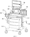
FIG. 1 is a schematic structural diagram of an anesthesia machine provided in an embodiment of the disclosure; -
FIG. 2 is a schematic diagram of the anesthesia machine ofFIG. 1 at another angle; -
FIG. 3 is a schematic diagram of the anesthesia machine ofFIG. 1 at another angle; -
FIG. 4 is a schematic diagram of the anesthesia machine ofFIG. 1 at another angle; and -
FIG. 5 is a schematic diagram of the anesthesia machine ofFIG. 1 at another angle. - List of reference numerals:
10. Host case; 11. Main rack case; 111. Worktable top; 112. Base; 12. Main control case; 20. Display apparatus; 21. Display device; 22. Display shell; 30. Anesthetic evaporator; 40. Control panel; 50. Breathing circuit; 51. Carbon dioxide absorption tank; 60. Main control board; 70. Control board; 80. Power supply interface; 81. Auxiliary output interface; 82. Power input interface; 90. Gas source interface; 100. Pressure detection assembly; 110. AGSS module; 120. Plug-in module interface; 130. Power supply apparatus. - The technical solutions of the embodiments of the disclosure will be described below clearly and comprehensively in conjunction with accompanying drawings of the embodiments of the disclosure. Apparently, the embodiments described are some of, rather than all of, the embodiments of the disclosure. All other embodiments obtained by persons of ordinary skill in the art based on the embodiments of the disclosure without creative efforts shall fall within the scope of protection of the disclosure.
- In the description of the disclosure, it should be understood that the orientation or position relationship indicated by the terms "centre", "longitudinal", "transverse", "length", "width", "thickness", "upper", "lower", "front", "rear", "left", "right", "vertical", "horizontal", "top", "bottom", "inner", "outer", "clockwise", "counterclockwise", etc. are based on the orientation or position relationship shown in the accompanying drawings and are intended to facilitate the description of the disclosure and simplify the description only, rather than indicating or implying that the apparatus or element referred to must have a particular orientation or be constructed and operated in a particular orientation, and therefore cannot be understood as limiting the disclosure. In addition, the terms "first" and "second" are used for descriptive purposes only, and cannot be construed as indicating or implying relative importance or implicitly indicating the number of technical features indicated. Thus, the features defined with "first" and "second" may explicitly or implicitly include one or more of the features. In the description of the disclosure, the meaning of "a plurality of' is two or more, unless specifically and specifically limited otherwise.
- Some embodiments of the disclosure will be described in detail below with reference to the drawings. In the case of no conflict, the embodiments and the features thereof described below may be combined with each other.
- The anesthesia machine of the disclosure belongs to the technical field of medical devices. An anesthesia machine is one of the most commonly used devices in an operating room and is a medical device mainly for adjusting a consciousness level and a pain level of a patient during a surgery.
- In general, the anesthesia machine includes a gas supply part, a control part, an anesthesia ventilation circuit part, a waste gas discharging part, an anesthetic evaporator, and so on, where the control part includes a control panel, a power input module, an auxiliary output module, a gas pressure detection module, an anesthetic evaporator control module, a plug-in module, an AGSS module and a display module, and so on; and these electronic modules may generate heat during the operation of the anesthesia machine, and when the heat is accumulated too much, it is likely to cause failures of electronic or gas circuit components, and even cause risks of fire, etc.
- At present, the anesthesia machine is generally provided with a heat dissipation hole and a cooling fan at a position where heat accumulates, so as to forcibly blow out the heat inside the anesthesia machine and introduce cold air, enabling each component in the anesthesia machine to work normally within a specified temperature range thereof. However, the cooling fan not only has an ineffective gap, but also easily generates noise during operation, which causes an adverse effect on an operating room environment.
- As shown in
FIGS. 1-5 , the disclosure provides an anesthesia machine, including ahost case 10, adisplay apparatus 20, ananesthetic evaporator 30, an anesthesia ventilation circuit, amain control board 60, apower supply interface 80 and agas source interface 90, where thegas source interface 90 and thepower supply interface 80 are both arranged on thehost case 10, theanesthetic evaporator 30 is detachably connected to thehost case 10, thegas source interface 90 is connected to the anesthesia ventilation circuit, and at least part of the anesthesia ventilation circuit is arranged in thehost case 10. In this embodiment, thedisplay apparatus 20 includes adisplay device 21 and adisplay shell 22 for fixing thedisplay device 21, themain control board 60 is arranged on thedisplay shell 22, and themain control board 60 is electrically connected to thepower supply interface 80 and thedisplay device 21. - After the above technical solution is used, during the operation of the anesthesia machine, the amounts of heat generated by components inside the anesthesia machine are different. For example, the
main control board 60 is a component with a large amount of heat itself, while a control valve on the anesthesia ventilation circuit is a component with a small amount of heat or no heat; when the components such as themain control board 60 and the anesthesia ventilation circuit are integrated in thehost case 10, interference will occur between the components such as themain control board 60 and the anesthesia ventilation circuit, and the component releasing a large amount of heat will affect the component with a small amount of heat or no heat, thereby shortening the service life of the component with a small amount of heat or no heat. Also, arranging themain control board 60 with a large amount of heat on thedisplay shell 22 in the disclosure may not only prevent the heat generated by themain control board 60 during operation from affecting the operation of each component in thehost case 10, but also ensure that each component in thehost case 10 is capable of operating at a safe operating temperature; furthermore, heat dissipation of themain control board 60 is facilitated, a sufficient heat dissipation space is provided for themain control board 60 to ensure that themain control board 60 is capable of dissipating heat to the surroundings by means of thedisplay shell 22. - In an optional embodiment, the
main control board 60 may be arranged on an inner side of thedisplay shell 22, and themain control board 60 may also be arranged on an outer side of thedisplay shell 22. When themain control board 60 is arranged on the outer side of thedisplay shell 22, themain control board 60 may be installed in a box and then the box is fixed to the outer side of thedisplay shell 22, and the shape and size of the box may match the shape and size of thedisplay shell 22 to ensure a structural shape of the exterior of the anesthesia machine. Meanwhile, a groove for placing themain control board 60 may also be provided on the outer side of thedisplay shell 22, and is then covered with a corresponding cover to protect themain control board 60, etc. This arrangement is mainly intended to arrange themain control board 60 on thedisplay shell 22, but a fixation method therefor is not limited in the disclosure. - In an optional embodiment, a heat dissipation structure is arranged on the anesthesia machine, the heat dissipation structure is installed on the
display shell 22, and the heat dissipation structure corresponds to themain control board 60 in position, such that the heat generated by themain control board 60 during operation can be rapidly diffused into the air by means of the heat dissipation structure, achieving a cooling effect. - Specifically, the heat dissipation structure may include an air intake hole and an air outlet hole formed in the
display shell 22, where the air intake hole and the air outlet hole are in communication to form a cooling air channel, and the cooling air channel runs through an outer surface of themain control board 60; when the anesthesia machine operates, the heat generated by themain control board 60 due to the operation can be released into the air by means of an air flow in the cooling air channel, ensuring that themain control board 60 can operate at a specified temperature, and prolonging the service life of themain control board 60. - In order to improve the temperature reduction and cooling efficiency of the
display shell 22, thedisplay shell 22 may also be provided with a miniature cooling fan, and the cooling fan can accelerate the discharge of a hot air in thedisplay shell 22 without increasing the noise of the anesthesia machine, nor causing an adverse effect on an operating room environment. - In addition, the heat dissipation structure may further include a heat sink, where the heat sink is closely adhered to the
main control board 60, maximally increasing the heat dissipation area of themain control board 60, so that electronic elements on themain control board 60 sufficiently dissipate heat. The heat sink may be a heat dissipation fin made of an aluminum alloy material, and the size and shape thereof may be the size and shape of themain control board 60, such that the heat dissipation effect of the heat dissipation structure can be effectively increased. - In an optional embodiment, the heat dissipation structure includes a heat conducting pad, where one end of the heat conducting pad abuts against the
main control board 60, and the other end of the heat conducting pad abuts against thedisplay shell 22, such that the heat generated during the operation of themain control board 60 can be transferred to thedisplay shell 22 by means of the heat conducting pad, and then diffused into the air by means of thedisplay shell 22; alternatively, the inner side of thedisplay shell 22 is provided with a metal frame, and the heat conducting pad is connected to the metal frame and diffuses the heat generated during the operation of themain control board 60 into the air by means of the metal frame, etc. - After the above technical solution is used, since the heat dissipation structure is arranged on the
display shell 22, the heat dissipation structure can diffuse the heat generated during the operation of themain control board 60 into the air, and can discharge the heat inside thedisplay shell 22 to the outside air, such that the heat dissipation effect of themain control board 60 is more obvious, ensuring that themain control board 60 can operate at the specified temperature thereof, and prolonging the service life of themain control board 60. - In an optional embodiment, the
gas source interface 90 and thepower supply interface 80 are arranged separately to achieve gas-electricity separation, which can effectively and completely eradicate the contact between the anesthesia ventilation circuit and various components and/or cables, and avoid the occurrence of relevant safety accidents, so that the safety factor of thehost case 10 is higher, and the safety in use is ensured. Meanwhile, it also facilitates the arrangement of pipelines on the anesthesia ventilation circuit and the cables connected among the various components in thehost case 10. For example, since thegas source interface 90 and thepower supply interface 80 are respectively arranged on two sides of thehost case 10, the pipelines on the anesthesia ventilation circuit may be arranged along one side of thehost case 10, and the cables connected among the various components in thehost case 10 may be arranged along the other side of thehost case 10, avoiding the problem of entanglement of the cables and the pipelines crossing each other, which not only facilitates the orderly arrangement of the pipelines and the cables inside thehost case 10, but also avoids the influence of the heat generated by the cables during power supply on the pipelines, preventing the service life of the pipelines from being shortened. The embodiment has the characteristics of reasonable layout, convenient installation, quick maintenance, cost saving, etc. - In an optional embodiment, the
display apparatus 20 may be directly arranged on a front side of thehost case 10, or thedisplay apparatus 20 may be installed at an upper end of thehost case 10 by means of a display supporting frame. In this embodiment, thedisplay apparatus 20 is installed at the upper end of thehost case 10 by means of the display supporting frame, and themain control board 60 is arranged on the side of thedisplay shell 22 opposite to thedisplay device 21, such that heat generated during the operation of themain control board 60 can be rapidly diffused into the air by means of thedisplay shell 22 to play a cooling effect. - In an optional embodiment, the front side of the
host case 10 is provided with acontrol panel 40, and thecontrol panel 40 is used for a user to adjust parameter information of the anesthesia ventilation circuit and/or to display control parameters of the anesthesia ventilation circuit. - Specifically, the
control panel 40 includes one or more of a flow adjustment knob, a concentration adjustment knob and a touch screen, where a gas flow parameter in the anesthesia ventilation circuit may be adjusted by means of the flow adjustment knob, a gas concentration parameter and/or an anesthetic concentration parameter in the anesthesia ventilation circuit may be adjusted by means of the concentration adjustment knob, and the gas flow parameter, the gas concentration parameter and the anesthetic concentration parameter adjusted by means of the flow adjustment knob and/or the concentration adjustment knob may be displayed by the touch screen. Furthermore, the touch screen may also adjust one or more of ventilation and anesthesia control parameters, such as gas flow, gas concentration, and anesthetic concentration, and device control parameters; and thecontrol panel 40 may also include a switching apparatus of the device for turning on or off the device. - In an optional embodiment, the
anesthetic evaporator 30 is arranged on a left side or a right side of thecontrol panel 40, and thegas source interface 90 and thepower supply interface 80 are arranged on a back side of thehost case 10, thereby avoiding mutual interference among theanesthetic evaporator 30, thecontrol panel 40, thegas source interface 90 and thepower supply interface 80, and effectively controlling theanesthetic evaporator 30, thecontrol panel 40 and thepower supply interface 80 to have a sufficient heat dissipation space, so that the space on the anesthesia machine can be effectively used, and thus theanesthetic evaporator 30, thecontrol panel 40 and thepower supply interface 80 can be distributed to various regions of the anesthesia machine for heat dissipation. - Specifically, the right side of the
control panel 40 is provided with an open installation cavity, the open installation cavity is provided with a locking seat sliding rail and a gas circuit interface connected to the anesthesia ventilation circuit, and after theanesthetic evaporator 30 is installed in the open installation cavity by means of the locking seat sliding rail, theanesthetic evaporator 30 is in communication with the anesthesia ventilation circuit by means of the gas circuit interface, so that when a patient breathes by means of a ventilator connected in the anesthesia ventilation circuit, theanesthetic evaporator 30 generates anesthetic vapor to anesthetize the patient. - In an optional embodiment, the anesthesia machine further includes a
control board 70, thecontrol board 70 being configured to control power supply between components on the anesthesia machine, where thecontrol board 70 is arranged inside thehost case 10. - Specifically, the
control board 70 is electrically connected to thepower supply interface 80 to supply power for controlling the various components in the anesthesia machine; thecontrol board 70 may be arranged on a left side of an interior of thehost case 10, or thecontrol board 70 may also be arranged on a right side of the interior of thehost case 10, or thecontrol board 70 may also be arranged on a rear side of the interior of thehost case 10, or even thecontrol board 70 may also be arranged on a front side of the interior of thehost case 10, and may be fixed to any one side of thehost case 10 in a fixed manner, or fixed in the middle of thehost case 10 by means of a supporting frame, which is not limited in the disclosure. - In an optional embodiment, the
control board 70 is arranged on the back side of thehost case 10, and thecontrol board 70 is arranged below thepower supply interface 80, thereby facilitating the arrangement of the cables between thepower supply interface 80 and thecontrol board 70, also preventing thecontrol board 70, thecontrol panel 40 and thepower supply interface 80 from interfering with one another due to different amounts of heat during operation, ensuring the stability of the operation of thecontrol board 70, thecontrol panel 40 and thepower supply interface 80, and prolonging the service life of thecontrol board 70, thecontrol panel 40 and thepower supply interface 80. - In an optional embodiment, the anesthesia machine further includes a
power supply apparatus 130, thepower supply apparatus 130 being arranged on a bottom of an inner side of thehost case 10 or on abase 112 below thehost case 10, where thepower supply apparatus 130 is arranged separately from thecontrol board 70 and thecontrol panel 40 to reduce interference with thecontrol board 70 and thecontrol panel 40 by thepower supply apparatus 130, thereby reducing the influence on the service life of thecontrol board 70 and thecontrol panel 40. - In this embodiment, the
power supply apparatus 130 is a disposable or rechargeable power storage apparatus. In case of a sudden power failure during the use of an anesthetic, thepower supply apparatus 130 may supply power to the components inside the anesthesia machine by means of thecontrol board 70, preventing the accidental power failure from causing harm to the patient. Thepower supply apparatus 130 is electrically connected to thepower supply interface 80 by means of thecontrol board 70, and when thepower supply apparatus 130 has insufficient power, thepower supply interface 80 can automatically charge thepower supply apparatus 130 to ensure that thepower supply apparatus 130 is always maintained in a fully charged state; when there is no current input on thepower supply interface 80, thecontrol board 70 controls thepower supply apparatus 130 to supply power to the components inside the anesthesia machine, thereby preventing the accidental power failure from causing harm to the patient. - In an optional embodiment, the
host case 10 includes amain rack case 11 and amain control case 12, where a lower end of themain rack case 11 is provided with abase 112, and universal wheels are installed on the base 112 to facilitate the movement of thehost case 10, making the anesthesia machine more convenient to use. In this embodiment, themain control case 12 is arranged at an upper end of themain rack case 11, thecontrol panel 40 is arranged on themain control case 12, thedisplay apparatus 20 is arranged at an upper end of themain control case 12, and thepower supply apparatus 130 is arranged at a bottom end of themain rack case 11 or below the base 112 so as to achieve the distribution of heat generating components in the anesthesia machine and also ensure the heat dissipation effect of the heat generating components. The heat generating components inside the anesthesia machine can not only be distributed scientifically and reasonably in the regions of the anesthesia machine according to heat generating conditions of the heat generating components inside the anesthesia machine, but also facilitate good heat dissipation of the heat generating components inside the anesthesia machine. For example, thepower supply apparatus 130 is arranged below thebase 112, themain control board 60 is arranged on thedisplay shell 22 at the upper end of themain control case 12, etc. - In an optional embodiment, the
gas source interface 90 is arranged on themain rack case 11, and/or thepower supply interface 80 is arranged on themain control case 12 to achieve gas-electricity separation and avoid safety accidents caused by gas-electricity cross contact, thus reducing hidden safety hazards. In this embodiment, thegas source interface 90 is arranged on themain rack case 11, thecontrol board 70 and thepower supply interface 80 are both arranged on themain control case 12, and thecontrol board 70 is located below thepower supply interface 80, so that themain rack case 11 and themain control case 12 can form a gas cavity and a cable cavity that are independent of each other, which not only facilitates the arrangement of cables and pipelines inside the anesthesia machine, but also facilitates the installation and maintenance of the anesthesia machine, saving time and manpower. - In an optional embodiment, an upper surface of the
main rack case 11 connected to themain control case 12 forms aworktable top 111, where theanesthetic evaporator 30 is detachably placed on theworktable top 111, and the worktable top is configured to place medical instruments commonly used during a surgery and notes to be recorded by medical personnel in work. In this embodiment, theanesthetic evaporator 30 is detachably placed in the open installation cavity on the right side of thecontrol panel 40, a layered storage cabinet is arranged on themain rack case 11, and the layered storage cabinet is arranged at an upper end of the base 112 to facilitate the storage of surgical supplies and provide assistance for surgery; and the structural design is relatively reasonable, not only facilitating the taking and placement of theanesthetic evaporator 30, but also improving the working efficiency of medical care personnel. - In an optional embodiment, the
power supply interface 80 includes anauxiliary output interface 81 and apower input interface 82, thepower input interface 82 being arranged on one side of theauxiliary output interface 81, where theauxiliary output interface 81 is configured to establish an electrical connection or a communication connection to an auxiliary device, the auxiliary device including an ultrasonic instrument, etc.; and thepower input interface 82 is configured to convert an alternating voltage into an operating voltage of the anesthesia machine. - Specifically, an AC-DC power module and an auxiliary output module are arranged on the anesthesia machine, and the
auxiliary output interface 81 is electrically connected to the auxiliary output module, such that the auxiliary device can be electrically connected to the auxiliary output module; and thepower input interface 82 is electrically connected to the AC-DC power module, and the AC-DC power module is configured to convert a 220V alternating voltage into a 12v direct voltage specially used for the anesthesia machine. In this embodiment, theauxiliary output interface 81 is arranged on a left side or a rear side of thepower input interface 82, which is mainly aimed to facilitate the arrangement of the cables connected to theauxiliary output interface 81 and thepower input interface 82, to avoid mutual crossing between the cables and to effectively reduce the loss of use of the cables, and to facilitate maintenance. - In an optional embodiment, the
control board 70 is arranged on a back side of themain control case 12, and theauxiliary output interface 81 and thepower input interface 82 are both arranged above thecontrol board 70. Specifically, theauxiliary output interface 81 is installed on theauxiliary output interface 81, thepower input interface 82 is installed on the AC-DC power module, namely, theauxiliary output interface 81 is installed on the back side of themain control case 12 by means of the auxiliary output module, thepower input interface 82 is installed on the back side of themain control case 12 by means of the AC-DC power module, and thecontrol board 70 is arranged below the auxiliary output module and the AC-DC power module, which not only ensures the heat dissipation space of thecontrol board 70, the auxiliary output module and the AC-DC power module, but also facilitates the arrangement of the cables among thecontrol board 70, the auxiliary output module and the AC-DC power module, thus avoiding the crossing problem of the cables and solving the problem of mutual interference of the cables. - In an optional embodiment, the
control board 70 is arranged in themain rack case 11; or, thecontrol board 70 is arranged in themain control case 12, so that thecontrol board 70 having a sufficient heat dissipation space can be ensured, and the control board can also be protected to prevent liquid of thehost case 10 and so on from damaging thecontrol board 70. In addition, in order to better improve the heat dissipation effect of thecontrol board 70, vent holes may also be formed in themain rack case 11 and/or themain control case 12, and the components on thecontrol board 70 may be cooled down to protect thecontrol board 70. - In an optional embodiment, the anesthesia machine further includes an
AGSS module 110, theAGSS module 110 being arranged on a side of thehost case 10, and theAGSS module 110 being in communication with the anesthesia ventilation circuit, where theAGSS module 110 refers to an anesthetic gas purification system, and is intended to prevent the contamination of a waste anesthetic gas in the anesthesia machine, avoiding that the waste anesthetic gas causes air contamination in the operating room and thus affects the health of medical personnel. - In an optional embodiment, the anesthesia machine further includes a plug-in
module interface 120, the plug-inmodule interface 120 being arranged on thehost case 10 and being configured to be connected to a plug-in box module of the anesthesia machine, and the plug-in box module including a heart rate monitor and an electrocardiograph monitor, and so on, which may be specifically selected according to user requirements. In this embodiment, the plug-in box module is connected to themain control board 60 by means of the plug-inmodule interface 120 and forwards data obtained thereby to themain control board 60, and themain control board 60 processes the received monitoring data and displays same by thedisplay device 21. The plug-inmodule interface 120 is arranged on the left side or the right side of thehost case 10 to facilitate the fixing and maintenance of the plug-in box module and also facilitate the addition or replacement of the plug-in box module. - In an optional embodiment, the plug-in
module interface 120 and theAGSS module 110 are located on the same side, and the plug-inmodule interface 120 is arranged at an upper end of theAGSS module 110, avoiding that the plug-in box module cannot be installed on the anesthesia machine due to a limited space, and also ensuring the neatness of the appearance of the anesthesia machine. In this embodiment, theanesthetic evaporator 30 is placed on theworktable top 111 at the right side of thecontrol panel 40, and the plug-inmodule interface 120 and theAGSS module 110 are arranged on themain rack case 11 at the left side of theworktable top 111, so that the plug-inmodule interface 120, theAGSS module 110 and theanesthetic evaporator 30 can be reasonably and effectively arranged, the balance of an anesthesia machine cart can also be ensured, and the movement of the anesthesia machine cart by the medical personnel with handles at two sides of theworktable top 111 is facilitated. - In an optional embodiment, the anesthesia ventilation circuit includes a
breathing circuit 50, a driving gas branch providing a driving gas, a fresh gas branch providing a fresh gas, and a bellows-free gas exchanger isolating the driving gas from a breathing circuit gas. In general, thebreathing circuit 50 is provided with a carbondioxide absorption tank 51, and the driving gas branch and the fresh gas branch are both connected to thebreathing circuit 50. The carbondioxide absorption tank 51 is mainly used for filtering out the carbon dioxide exhaled by the patient, and then re-enters the patient's body by means of thebreathing circuit 50 together with the fresh gas and the anesthetic vapor generated by theanesthetic evaporator 30, where the driving gas can be oxygen or air, and the gas flow parameter, the gas concentration parameter, the anesthetic concentration parameter of the anesthesia ventilation circuit and so on may be controlled by means of thecontrol panel 40. - Specifically, the anesthesia ventilation circuit further includes a
pressure detection assembly 100, thepressure detection assembly 100 being configured to detect a gas pressure of the anesthesia ventilation circuit. In this embodiment, thepressure detection assembly 100, thecontrol panel 40 and thecontrol board 70 are separately arranged on thehost case 10, so that the problem of not completely separating gas and electricity in the anesthesia machine is solved, and the safety of the anesthesia machine in use is improved. - In this embodiment, a clamping groove is formed in a side wall inside the
host case 10, and a pipeline on the fresh gas branch is fixed to the side wall inside thehost case 10 by means of the clamping groove, where the driving gas branch and thebreathing circuit 50 are arranged on the outer side of thehost case 10. - Specifically, the
pressure detection assembly 100 is arranged in themain control case 12, or thepressure detection assembly 100 is arranged at a position of themain rack case 11 on the worktable top, so as to ensure that thepressure detection assembly 100 and the pipeline on the fresh gas branch can be arranged separately from thecontrol panel 40 and thecontrol board 70, avoiding safety accidents caused by gas-electricity cross contact, and reducing hidden safety hazards. - With the above technical solution, the
anesthetic evaporator 30, themain control board 60, thecontrol board 70, thepower supply interface 80 and thepower supply apparatus 130 can be effectively distributed in the regions of the anesthesia machine according to the heat generated by each component in the anesthesia machine during operation, thereby avoiding mutual interference of the components, namely, the influence of a component with a large amount of heat on a component with a small amount of heat, and also shortening the service life of the component with a small amount of heat; also, it is also possible to arrange different heat dissipation structures according to the amounts of heat of components to meet the heat dissipation requirements of different components, so that the components can operate at a safe temperature, thereby solving the problem of component failure caused by the heat generated by the components centralized together during the operation of the anesthesia machine, or even avoiding the risk of possible fires. - Furthermore, the disclosure further separates the gas-electricity components inside the anesthesia machine, avoiding the problem that gas circuit components fail due to heat accumulation during the operation of electronic components, also avoiding the safety accidents caused by the gas-electricity cross contact, and reducing the hidden safety hazards. The components inside the anesthesia machine may be distributed in the various regions inside the anesthesia machine according to parameter information of the components; for example, the amount of heat generated by the
main control board 60 is calculated according to the number of components on themain control board 60, the power of a chip, the working frequency of the chip, the manufacturer information of the chip, the size of a capacitor, the manufacturer information of the capacitor, the size of a resistor, and so on, then themain control board 60 is arranged in thedisplay shell 22, so that the heat dissipation effect of themain control board 60 is ensured, forced heat dissipation using a cooling fan is prevented from affecting the working environment of the operating room, the power consumption of the anesthesia machine and the risk of themain control board 60 failing to dissipate heat due to the failure of the cooling fan, and so on are also reduced, thereby achieving many purposes at one stroke. - In the description of the disclosure, it should be noted that unless otherwise expressly specified and defined, the terms "installation", "connecting" and "connection" should be understood in a broad sense, for example, it may be a fixed connection, a detachable connection, or an integrated connection. It may be a mechanical connection or an electrical connection. It may be a direct connection or an indirect connection by means of an intermediate medium, and may be an internal communication of two elements or an interaction relationship of the two elements. For persons of ordinary skill in the art, specific meanings of the foregoing terms in the disclosure may be understood according to specific situations.
- In this disclosure, unless otherwise expressly specified and defined, the expression of the first feature being "above" or "under" the second feature may include direct contact of the first feature and the second feature, and may also include that the first and second features are not in direct contact but are in contact by means of additional features therebetween. Furthermore, the expression the first feature being "over", "above" and "on top of' the second feature may be the case that the first feature is directly above or obliquely above the second feature, or only means that the level of the first feature is higher than that of the second feature. The expression the first feature being "underneath", "below" and "beneath" the second feature may be the case that the first feature is directly below or obliquely below the second feature, or only means that the level of the first feature is less than that of the second feature.
- This description above provides many different embodiments or examples that can be used to implement different structures of the disclosure. In order to simplify the description of the disclosure, the components and arrangements of specific examples are described above. They are, of course, merely examples and are not intended to limit the disclosure. Furthermore, the disclosure may repeat reference numbers and/or reference letters in different examples, such repetition being for purposes of simplicity and clarity and not in itself indicative of a relationship between various embodiments and/or arrangements as discussed. In addition, the disclosure provides examples of various specific processes and materials herein, but those of ordinary skill in the art may recognize the application of other processes and/or the use of other materials.
- In the description, the explanation with reference to the terms such as "an embodiment", "some embodiments", "exemplary embodiments", "examples", "specific examples", or "some examples" means that specific features, structures, materials, or characteristics described in combination with the embodiment(s) or example(s) are included in at least one embodiment or example of the disclosure. In the description, the illustrative expressions of the above-mentioned terms do not necessarily refer to the same embodiments or examples. Moreover, the specific features, structures, materials, or characteristics described herein may be combined in a suitable manner in any one or more embodiments or examples.
- Although the embodiments of the disclosure have been shown and described, it will be appreciated by those of ordinary skill in the art that: various changes, modifications, substitutions and alterations can be made to these embodiments without departing from the principles and spirit of the disclosure, the scope of which is defined by the claims and their equivalents.
Claims (21)
- An anesthesia machine, characterized in that the anesthesia machine comprises: a gas source interface, an anesthesia ventilation circuit, an anesthetic evaporator, a host case, a main control board, a display apparatus and a power supply interface; whereinthe gas source interface and the power supply interface are arranged on the host case, and the anesthetic evaporator is detachably connected to the host case;the anesthesia ventilation circuit connects with the gas source interface, and at least part of the anesthesia ventilation circuit is arranged in the host case;the display apparatus includes a display device and a display shell for fixing the display device; andthe main control board is arranged on the display shell, and the power supply interface electrically connects with the main control board and the display device.
- The anesthesia machine of claim 1, characterized in that the gas source interface and the power supply interface are separately arranged.
- The anesthesia machine of claim 1, characterized in that a control panel is arranged on a front side of the host case for adjusting parameter information of the anesthesia ventilation circuit and/or displaying control parameter(s) of the anesthesia ventilation circuit.
- The anesthesia machine of claim 3, characterized in that the anesthetic evaporator is arranged on a left side or a right side of the control panel, wherein the gas source interface and the power supply interface are arranged on a back side of the host case.
- The anesthesia machine of claim 3, characterized in that the anesthesia machine further comprises:
a control board configured to control power supply for various components of the anesthesia machine, wherein the control board is arranged inside the host case - The anesthesia machine of claim 5, characterized in that the control board is arranged on a back side of the host case and below the power supply interface.
- The anesthesia machine of any one of claims 1 to 6, characterized in that the anesthesia machine further comprises:
a power supply apparatus arranged on a bottom of an inner side of the host case or on a base below the host case, the power supply apparatus being arranged separately from the control board and the control panel. - The anesthesia machine of claim 7, characterized in that the host case comprises:a main rack case; anda main control case arranged above the main rack case, the control panel being arranged on the main control case, and the display apparatus being arranged above the main control case.
- The anesthesia machine of claim 8, characterized in that the gas source interface is arranged on the main rack case, and/or the power supply interface is arranged on the main control case.
- The anesthesia machine of claim 8, characterized in that an upper surface of the main rack case forms a worktable top, and the anesthetic evaporator is detachably placed on the worktable top.
- The anesthesia machine of claim 10, characterized in that the power supply interface comprises:an auxiliary output interface; anda power input interface arranged on one side of the auxiliary output interface.
- The anesthesia machine of claim 11, characterized in that the control board is arranged on a back side of the main control case, and the auxiliary output interface and the power input interface are both arranged above the control board.
- The anesthesia machine of claim 8, characterized in that the control board is arranged in the main rack case; or the control board is arranged in the main control case.
- The anesthesia machine of claim 1, characterized in that the anesthesia machine further comprises:
an AGSS module arranged on a side of the host case, the AGSS module being in communication with the anesthesia ventilation circuit. - The anesthesia machine of claim 14, characterized in that the anesthesia machine further comprises:
a plug-in module interface arranged on the host case. - The anesthesia machine of claim 15, characterized in that the plug-in module interface and the AGSS module are located on the same side.
- The anesthesia machine of claim 10, characterized in that the anesthesia ventilation circuit comprises a breathing circuit, a driving gas branch and a fresh gas branch, wherein the fresh gas branch is arranged on an inner side of the host case, and the driving gas branch and the breathing circuit are arranged on an outer side of the host case.
- The anesthesia machine of claim 17, characterized in that the anesthesia ventilation circuit further comprises:
a pressure detection assembly configured to detect a gas pressure of the anesthesia ventilation circuit, wherein the pressure detection assembly, the control panel and the control board are separately arranged on the host case. - The anesthesia machine of claim 18, characterized in that the pressure detection assembly is arranged in the main control case, or the pressure detection assembly is arranged on the worktable top of the main rack case.
- The anesthesia machine of claim 1, characterized in that a heat dissipation structure is arranged on the display shell, and the heat dissipation structure corresponds to the main control board in position.
- The anesthesia machine of claim 20, characterized in that the heat dissipation structure includes a heat conducting pad, one end of the heat conducting pad abutting against the main control board, and the other end of the heat conducting pad abutting against the display shell.
Applications Claiming Priority (1)
| Application Number | Priority Date | Filing Date | Title |
|---|---|---|---|
| PCT/CN2019/130213 WO2021134372A1 (en) | 2019-12-30 | 2019-12-30 | Anesthesia machine |
Publications (3)
| Publication Number | Publication Date |
|---|---|
| EP4085954A1 true EP4085954A1 (en) | 2022-11-09 |
| EP4085954A4 EP4085954A4 (en) | 2023-01-11 |
| EP4085954B1 EP4085954B1 (en) | 2025-03-19 |
Family
ID=76687464
Family Applications (1)
| Application Number | Title | Priority Date | Filing Date |
|---|---|---|---|
| EP19958324.6A Active EP4085954B1 (en) | 2019-12-30 | 2019-12-30 | Anesthesia machine |
Country Status (3)
| Country | Link |
|---|---|
| EP (1) | EP4085954B1 (en) |
| CN (1) | CN114555162B (en) |
| WO (1) | WO2021134372A1 (en) |
Families Citing this family (1)
| Publication number | Priority date | Publication date | Assignee | Title |
|---|---|---|---|---|
| FR3127408B1 (en) * | 2021-09-29 | 2024-05-10 | Inosystems | Hospital trolley for transporting gas bottles, particularly medical NO |
Family Cites Families (18)
| Publication number | Priority date | Publication date | Assignee | Title |
|---|---|---|---|---|
| GB255303A (en) * | 1925-12-07 | 1926-07-22 | Maurice Alland | Improvements in or relating to propelling pencils |
| US20050005932A1 (en) * | 2003-03-19 | 2005-01-13 | Berman Mitchell F. | Integrated anesthesia machine |
| NZ710686A (en) * | 2003-06-20 | 2017-02-24 | Resmed Ltd | Breathable gas apparatus with humidifier |
| US9604020B2 (en) * | 2009-10-16 | 2017-03-28 | Spacelabs Healthcare Llc | Integrated, extendable anesthesia system |
| GB2500538B (en) * | 2010-12-17 | 2017-09-13 | Spacelabs Healthcare Llc | Integrated, extendable anesthesia system |
| WO2012158720A1 (en) * | 2011-05-15 | 2012-11-22 | Spacelabs Healthcare, Llc | User configurable central monitoring station |
| CN102724811B (en) * | 2012-06-13 | 2015-05-06 | 深圳市华星光电技术有限公司 | Liquid crystal display device and PCB (printed circuit board) for same |
| US9884157B2 (en) * | 2013-03-15 | 2018-02-06 | Microdose Therapeutx, Inc. | Inhalation device, control method and computer program |
| WO2014178730A2 (en) * | 2013-04-30 | 2014-11-06 | Iac Ip Limited | Anaesthetic machine |
| CN105759923A (en) * | 2014-12-18 | 2016-07-13 | 研祥智能科技股份有限公司 | Separating type radiating device and method for closed industrial computer |
| CN104815375A (en) * | 2015-04-19 | 2015-08-05 | 陈曦 | Operative anesthesia machine |
| CN105597210B (en) * | 2016-02-25 | 2018-05-11 | 深圳市诺然美泰科技股份有限公司 | The anesthesiaing system of compatible ascending manner and descending manner bellows breathing circuit |
| CN205434615U (en) * | 2016-03-04 | 2016-08-10 | 孙玉静 | Anesthesia machine with heat insulation part and radiating piece |
| CN106178211A (en) * | 2016-08-19 | 2016-12-07 | 陆峰 | Ventilation anesthesia outfit |
| CN206424397U (en) * | 2016-10-27 | 2017-08-22 | 遵义医学院附属医院 | A kind of improved structure of surgery anesthesia machine |
| CN106693135A (en) * | 2016-11-21 | 2017-05-24 | 闫玉荣 | Anesthesia machine and reminding device for same |
| CN114042216A (en) * | 2018-06-26 | 2022-02-15 | 深圳迈瑞生物医疗电子股份有限公司 | Anesthesia machine and system |
| CN109731200B (en) * | 2019-01-28 | 2021-02-12 | 郑州大学第三附属医院 | A suction-type anesthesia machine for general anesthesia |
-
2019
- 2019-12-30 CN CN201980100194.3A patent/CN114555162B/en active Active
- 2019-12-30 EP EP19958324.6A patent/EP4085954B1/en active Active
- 2019-12-30 WO PCT/CN2019/130213 patent/WO2021134372A1/en not_active Ceased
Also Published As
| Publication number | Publication date |
|---|---|
| CN114555162A (en) | 2022-05-27 |
| WO2021134372A1 (en) | 2021-07-08 |
| EP4085954B1 (en) | 2025-03-19 |
| CN114555162B (en) | 2024-11-26 |
| EP4085954A4 (en) | 2023-01-11 |
Similar Documents
| Publication | Publication Date | Title |
|---|---|---|
| JP6704094B2 (en) | System and method for producing nitric oxide | |
| JP2022002719A (en) | Systems and methods for generating nitric oxide | |
| US6234172B1 (en) | Control and display configuration layout | |
| CN113521457A (en) | Modular ventilation system | |
| MXPA04003443A (en) | Apparatuses and methods for providing a conscious patient relief from pain and anxiety associated with medical or surgical procedures according to appropriate clinical heuristics. | |
| WO2020000208A1 (en) | Anesthesia machine and system | |
| US9757531B2 (en) | Transportable medical air compressor | |
| EP4085954B1 (en) | Anesthesia machine | |
| CN106267499A (en) | A kind of Anesthesia Department unsettled anesthesia outfit of head-rest type | |
| Reimer et al. | High-flow nasal cannula in transport: process, results, and considerations | |
| CN208837928U (en) | A kind of portable cross-platform medical aid unit | |
| CN221154992U (en) | Shell and breathing machine | |
| CN108545091A (en) | A kind of health medical treatment train with operating room | |
| US20230310787A1 (en) | Anesthesia respiration apparatus, anesthesia respiration gas path system and anesthetic gas path system | |
| CN118892595A (en) | Ventilation equipment and medical devices | |
| CN108209888A (en) | A kind of cross-platform medical aid multi-parameter life sign monitor device | |
| CN117653486A (en) | A mobile critical illness transport emergency equipment | |
| CN221654946U (en) | A critical care transport emergency integrated device that can be combined with a transport bed | |
| CN119233588A (en) | Medical ventilation device | |
| Vos et al. | Interhospital paediatric intensive care transport: a novel transport unit based on a standard ambulance trolley | |
| Chung | Anesthesia Equipment for the Oral and Maxillofacial Surgery | |
| CN219331950U (en) | Side plate structure of portable first-aid equipment | |
| CN216652726U (en) | Clinical breathing device who uses of department of anesthesia | |
| CN221491096U (en) | Adjustable clinical ventilator for neonate | |
| CN212699972U (en) | Medical electric control oxygen therapy breathing machine |
Legal Events
| Date | Code | Title | Description |
|---|---|---|---|
| STAA | Information on the status of an ep patent application or granted ep patent |
Free format text: STATUS: THE INTERNATIONAL PUBLICATION HAS BEEN MADE |
|
| PUAI | Public reference made under article 153(3) epc to a published international application that has entered the european phase |
Free format text: ORIGINAL CODE: 0009012 |
|
| STAA | Information on the status of an ep patent application or granted ep patent |
Free format text: STATUS: REQUEST FOR EXAMINATION WAS MADE |
|
| 17P | Request for examination filed |
Effective date: 20220727 |
|
| AK | Designated contracting states |
Kind code of ref document: A1 Designated state(s): AL AT BE BG CH CY CZ DE DK EE ES FI FR GB GR HR HU IE IS IT LI LT LU LV MC MK MT NL NO PL PT RO RS SE SI SK SM TR |
|
| A4 | Supplementary search report drawn up and despatched |
Effective date: 20221208 |
|
| RIC1 | Information provided on ipc code assigned before grant |
Ipc: A61G 12/00 20060101ALI20221202BHEP Ipc: A61M 16/01 20060101AFI20221202BHEP |
|
| DAV | Request for validation of the european patent (deleted) | ||
| DAX | Request for extension of the european patent (deleted) | ||
| GRAP | Despatch of communication of intention to grant a patent |
Free format text: ORIGINAL CODE: EPIDOSNIGR1 |
|
| STAA | Information on the status of an ep patent application or granted ep patent |
Free format text: STATUS: GRANT OF PATENT IS INTENDED |
|
| INTG | Intention to grant announced |
Effective date: 20241008 |
|
| GRAS | Grant fee paid |
Free format text: ORIGINAL CODE: EPIDOSNIGR3 |
|
| GRAA | (expected) grant |
Free format text: ORIGINAL CODE: 0009210 |
|
| STAA | Information on the status of an ep patent application or granted ep patent |
Free format text: STATUS: THE PATENT HAS BEEN GRANTED |
|
| P01 | Opt-out of the competence of the unified patent court (upc) registered |
Free format text: CASE NUMBER: APP_4889/2025 Effective date: 20250129 |
|
| AK | Designated contracting states |
Kind code of ref document: B1 Designated state(s): AL AT BE BG CH CY CZ DE DK EE ES FI FR GB GR HR HU IE IS IT LI LT LU LV MC MK MT NL NO PL PT RO RS SE SI SK SM TR |
|
| REG | Reference to a national code |
Ref country code: GB Ref legal event code: FG4D |
|
| REG | Reference to a national code |
Ref country code: CH Ref legal event code: EP |
|
| REG | Reference to a national code |
Ref country code: IE Ref legal event code: FG4D |
|
| REG | Reference to a national code |
Ref country code: DE Ref legal event code: R096 Ref document number: 602019067654 Country of ref document: DE |
|
| REG | Reference to a national code |
Ref country code: SE Ref legal event code: TRGR |
|
| PG25 | Lapsed in a contracting state [announced via postgrant information from national office to epo] |
Ref country code: RS Free format text: LAPSE BECAUSE OF FAILURE TO SUBMIT A TRANSLATION OF THE DESCRIPTION OR TO PAY THE FEE WITHIN THE PRESCRIBED TIME-LIMIT Effective date: 20250619 |
|
| PG25 | Lapsed in a contracting state [announced via postgrant information from national office to epo] |
Ref country code: FI Free format text: LAPSE BECAUSE OF FAILURE TO SUBMIT A TRANSLATION OF THE DESCRIPTION OR TO PAY THE FEE WITHIN THE PRESCRIBED TIME-LIMIT Effective date: 20250319 |
|
| REG | Reference to a national code |
Ref country code: LT Ref legal event code: MG9D |
|
| PG25 | Lapsed in a contracting state [announced via postgrant information from national office to epo] |
Ref country code: NO Free format text: LAPSE BECAUSE OF FAILURE TO SUBMIT A TRANSLATION OF THE DESCRIPTION OR TO PAY THE FEE WITHIN THE PRESCRIBED TIME-LIMIT Effective date: 20250619 |
|
| PG25 | Lapsed in a contracting state [announced via postgrant information from national office to epo] |
Ref country code: HR Free format text: LAPSE BECAUSE OF FAILURE TO SUBMIT A TRANSLATION OF THE DESCRIPTION OR TO PAY THE FEE WITHIN THE PRESCRIBED TIME-LIMIT Effective date: 20250319 |
|
| PG25 | Lapsed in a contracting state [announced via postgrant information from national office to epo] |
Ref country code: LV Free format text: LAPSE BECAUSE OF FAILURE TO SUBMIT A TRANSLATION OF THE DESCRIPTION OR TO PAY THE FEE WITHIN THE PRESCRIBED TIME-LIMIT Effective date: 20250319 |
|
| PG25 | Lapsed in a contracting state [announced via postgrant information from national office to epo] |
Ref country code: BG Free format text: LAPSE BECAUSE OF FAILURE TO SUBMIT A TRANSLATION OF THE DESCRIPTION OR TO PAY THE FEE WITHIN THE PRESCRIBED TIME-LIMIT Effective date: 20250319 Ref country code: GR Free format text: LAPSE BECAUSE OF FAILURE TO SUBMIT A TRANSLATION OF THE DESCRIPTION OR TO PAY THE FEE WITHIN THE PRESCRIBED TIME-LIMIT Effective date: 20250620 |
|
| REG | Reference to a national code |
Ref country code: NL Ref legal event code: MP Effective date: 20250319 |
|
| REG | Reference to a national code |
Ref country code: AT Ref legal event code: MK05 Ref document number: 1776446 Country of ref document: AT Kind code of ref document: T Effective date: 20250319 |
|
| PG25 | Lapsed in a contracting state [announced via postgrant information from national office to epo] |
Ref country code: NL Free format text: LAPSE BECAUSE OF FAILURE TO SUBMIT A TRANSLATION OF THE DESCRIPTION OR TO PAY THE FEE WITHIN THE PRESCRIBED TIME-LIMIT Effective date: 20250319 |
|
| PG25 | Lapsed in a contracting state [announced via postgrant information from national office to epo] |
Ref country code: SM Free format text: LAPSE BECAUSE OF FAILURE TO SUBMIT A TRANSLATION OF THE DESCRIPTION OR TO PAY THE FEE WITHIN THE PRESCRIBED TIME-LIMIT Effective date: 20250319 |
|
| PG25 | Lapsed in a contracting state [announced via postgrant information from national office to epo] |
Ref country code: ES Free format text: LAPSE BECAUSE OF FAILURE TO SUBMIT A TRANSLATION OF THE DESCRIPTION OR TO PAY THE FEE WITHIN THE PRESCRIBED TIME-LIMIT Effective date: 20250319 Ref country code: PT Free format text: LAPSE BECAUSE OF FAILURE TO SUBMIT A TRANSLATION OF THE DESCRIPTION OR TO PAY THE FEE WITHIN THE PRESCRIBED TIME-LIMIT Effective date: 20250721 |
|
| PG25 | Lapsed in a contracting state [announced via postgrant information from national office to epo] |
Ref country code: IT Free format text: LAPSE BECAUSE OF FAILURE TO SUBMIT A TRANSLATION OF THE DESCRIPTION OR TO PAY THE FEE WITHIN THE PRESCRIBED TIME-LIMIT Effective date: 20250319 Ref country code: PL Free format text: LAPSE BECAUSE OF FAILURE TO SUBMIT A TRANSLATION OF THE DESCRIPTION OR TO PAY THE FEE WITHIN THE PRESCRIBED TIME-LIMIT Effective date: 20250319 |
|
| PG25 | Lapsed in a contracting state [announced via postgrant information from national office to epo] |
Ref country code: AT Free format text: LAPSE BECAUSE OF FAILURE TO SUBMIT A TRANSLATION OF THE DESCRIPTION OR TO PAY THE FEE WITHIN THE PRESCRIBED TIME-LIMIT Effective date: 20250319 |
|
| PG25 | Lapsed in a contracting state [announced via postgrant information from national office to epo] |
Ref country code: EE Free format text: LAPSE BECAUSE OF FAILURE TO SUBMIT A TRANSLATION OF THE DESCRIPTION OR TO PAY THE FEE WITHIN THE PRESCRIBED TIME-LIMIT Effective date: 20250319 Ref country code: CZ Free format text: LAPSE BECAUSE OF FAILURE TO SUBMIT A TRANSLATION OF THE DESCRIPTION OR TO PAY THE FEE WITHIN THE PRESCRIBED TIME-LIMIT Effective date: 20250319 |
|
| PG25 | Lapsed in a contracting state [announced via postgrant information from national office to epo] |
Ref country code: RO Free format text: LAPSE BECAUSE OF FAILURE TO SUBMIT A TRANSLATION OF THE DESCRIPTION OR TO PAY THE FEE WITHIN THE PRESCRIBED TIME-LIMIT Effective date: 20250319 |
|
| PG25 | Lapsed in a contracting state [announced via postgrant information from national office to epo] |
Ref country code: SK Free format text: LAPSE BECAUSE OF FAILURE TO SUBMIT A TRANSLATION OF THE DESCRIPTION OR TO PAY THE FEE WITHIN THE PRESCRIBED TIME-LIMIT Effective date: 20250319 |
|
| PG25 | Lapsed in a contracting state [announced via postgrant information from national office to epo] |
Ref country code: IS Free format text: LAPSE BECAUSE OF FAILURE TO SUBMIT A TRANSLATION OF THE DESCRIPTION OR TO PAY THE FEE WITHIN THE PRESCRIBED TIME-LIMIT Effective date: 20250719 |
|
| REG | Reference to a national code |
Ref country code: DE Ref legal event code: R097 Ref document number: 602019067654 Country of ref document: DE |
|
| PGFP | Annual fee paid to national office [announced via postgrant information from national office to epo] |
Ref country code: DE Payment date: 20251211 Year of fee payment: 7 |
|
| PG25 | Lapsed in a contracting state [announced via postgrant information from national office to epo] |
Ref country code: DK Free format text: LAPSE BECAUSE OF FAILURE TO SUBMIT A TRANSLATION OF THE DESCRIPTION OR TO PAY THE FEE WITHIN THE PRESCRIBED TIME-LIMIT Effective date: 20250319 |
|
| PGFP | Annual fee paid to national office [announced via postgrant information from national office to epo] |
Ref country code: SE Payment date: 20251219 Year of fee payment: 7 |
|
| PLBE | No opposition filed within time limit |
Free format text: ORIGINAL CODE: 0009261 |
|
| STAA | Information on the status of an ep patent application or granted ep patent |
Free format text: STATUS: NO OPPOSITION FILED WITHIN TIME LIMIT |
|
| REG | Reference to a national code |
Ref country code: CH Ref legal event code: L10 Free format text: ST27 STATUS EVENT CODE: U-0-0-L10-L00 (AS PROVIDED BY THE NATIONAL OFFICE) Effective date: 20260128 |
|
| 26N | No opposition filed |
Effective date: 20251222 |