EP4085780A1 - Multi-layer braided upper - Google Patents
Multi-layer braided upper Download PDFInfo
- Publication number
- EP4085780A1 EP4085780A1 EP22174209.1A EP22174209A EP4085780A1 EP 4085780 A1 EP4085780 A1 EP 4085780A1 EP 22174209 A EP22174209 A EP 22174209A EP 4085780 A1 EP4085780 A1 EP 4085780A1
- Authority
- EP
- European Patent Office
- Prior art keywords
- footwear
- article
- shell
- coating
- outer braided
- Prior art date
- Legal status (The legal status is an assumption and is not a legal conclusion. Google has not performed a legal analysis and makes no representation as to the accuracy of the status listed.)
- Granted
Links
Images


Classifications
-
- A—HUMAN NECESSITIES
- A43—FOOTWEAR
- A43B—CHARACTERISTIC FEATURES OF FOOTWEAR; PARTS OF FOOTWEAR
- A43B1/00—Footwear characterised by the material
- A43B1/02—Footwear characterised by the material made of fibres or fabrics made therefrom
- A43B1/04—Footwear characterised by the material made of fibres or fabrics made therefrom braided, knotted, knitted or crocheted
-
- A—HUMAN NECESSITIES
- A43—FOOTWEAR
- A43B—CHARACTERISTIC FEATURES OF FOOTWEAR; PARTS OF FOOTWEAR
- A43B23/00—Uppers; Boot legs; Stiffeners; Other single parts of footwear
- A43B23/02—Uppers; Boot legs
- A43B23/0205—Uppers; Boot legs characterised by the material
- A43B23/0215—Plastics or artificial leather
-
- A—HUMAN NECESSITIES
- A43—FOOTWEAR
- A43B—CHARACTERISTIC FEATURES OF FOOTWEAR; PARTS OF FOOTWEAR
- A43B23/00—Uppers; Boot legs; Stiffeners; Other single parts of footwear
- A43B23/02—Uppers; Boot legs
- A43B23/0205—Uppers; Boot legs characterised by the material
- A43B23/0235—Different layers of different material
-
- A—HUMAN NECESSITIES
- A43—FOOTWEAR
- A43B—CHARACTERISTIC FEATURES OF FOOTWEAR; PARTS OF FOOTWEAR
- A43B23/00—Uppers; Boot legs; Stiffeners; Other single parts of footwear
- A43B23/02—Uppers; Boot legs
- A43B23/0245—Uppers; Boot legs characterised by the constructive form
- A43B23/0255—Uppers; Boot legs characterised by the constructive form assembled by gluing or thermo bonding
-
- A—HUMAN NECESSITIES
- A43—FOOTWEAR
- A43B—CHARACTERISTIC FEATURES OF FOOTWEAR; PARTS OF FOOTWEAR
- A43B23/00—Uppers; Boot legs; Stiffeners; Other single parts of footwear
- A43B23/02—Uppers; Boot legs
- A43B23/0245—Uppers; Boot legs characterised by the constructive form
- A43B23/026—Laminated layers
-
- B—PERFORMING OPERATIONS; TRANSPORTING
- B29—WORKING OF PLASTICS; WORKING OF SUBSTANCES IN A PLASTIC STATE IN GENERAL
- B29D—PRODUCING PARTICULAR ARTICLES FROM PLASTICS OR FROM SUBSTANCES IN A PLASTIC STATE
- B29D35/00—Producing footwear
- B29D35/12—Producing parts thereof, e.g. soles, heels, uppers, by a moulding technique
- B29D35/126—Uppers
-
- B—PERFORMING OPERATIONS; TRANSPORTING
- B29—WORKING OF PLASTICS; WORKING OF SUBSTANCES IN A PLASTIC STATE IN GENERAL
- B29D—PRODUCING PARTICULAR ARTICLES FROM PLASTICS OR FROM SUBSTANCES IN A PLASTIC STATE
- B29D35/00—Producing footwear
- B29D35/12—Producing parts thereof, e.g. soles, heels, uppers, by a moulding technique
- B29D35/14—Multilayered parts
- B29D35/146—Uppers
-
- A—HUMAN NECESSITIES
- A43—FOOTWEAR
- A43B—CHARACTERISTIC FEATURES OF FOOTWEAR; PARTS OF FOOTWEAR
- A43B23/00—Uppers; Boot legs; Stiffeners; Other single parts of footwear
- A43B23/02—Uppers; Boot legs
- A43B23/0205—Uppers; Boot legs characterised by the material
- A43B23/024—Different layers of the same material
-
- A—HUMAN NECESSITIES
- A43—FOOTWEAR
- A43B—CHARACTERISTIC FEATURES OF FOOTWEAR; PARTS OF FOOTWEAR
- A43B23/00—Uppers; Boot legs; Stiffeners; Other single parts of footwear
- A43B23/02—Uppers; Boot legs
- A43B23/0245—Uppers; Boot legs characterised by the constructive form
- A43B23/0265—Uppers; Boot legs characterised by the constructive form having different properties in different directions
- A43B23/027—Uppers; Boot legs characterised by the constructive form having different properties in different directions with a part of the upper particularly flexible, e.g. permitting articulation or torsion
-
- A—HUMAN NECESSITIES
- A43—FOOTWEAR
- A43B—CHARACTERISTIC FEATURES OF FOOTWEAR; PARTS OF FOOTWEAR
- A43B5/00—Footwear for sporting purposes
- A43B5/02—Football boots or shoes, i.e. for soccer, football or rugby
- A43B5/025—Football boots or shoes, i.e. for soccer, football or rugby characterised by an element which improves the contact between the ball and the footwear
Definitions
- aspects herein relate to a footwear upper having a braided structure with an outer coating that covers at least a portion of the braided upper.
- Newer methods also now include forming footwear uppers from a knitted textile. Still newer methods involve braiding a material for use as the footwear upper. Aspects herein relate to braided structures for footwear that are selectively coated in some areas.
- the upper has a medial side and a lateral side, and a toe end and a heel end.
- the upper has an inner booty, at least partially surrounded by an outer braided shell, made from a number of yarns that are braided together.
- a coating covers portions of the outer braided shell. In some aspects, this coating creates a textured surface. In some aspects this textured surface covers at least a portion of the bottom of the article of footwear.
- the upper has a medial side and a lateral side, and a toe end and a heel end.
- the upper has an inner knit booty, at least partially surrounded by an outer braided shell, made from a number of yarns that are braided together.
- the inner knit booty and the outer braided shell are coupled together with a thermoplastic material disposed over the outer braided shell.
- the inner booty and the outer braided shell may be coupled together with a thermoplastic material disposed between the outer braided shell and the inner booty.
- a coating covers portions of the outer braided shell. In some aspects, this coating creates a textured surface. In some aspects this textured surface covers at least a portion of the bottom of the article of footwear.
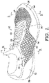
- FIG. 1 An article of footwear 10 is shown in FIG. 1 with a multi-layer upper having an inner booty 12, and an outer braided shell 14.
- the inner booty 12 is knitted.
- the inner booty 12 is formed in a circular knitting process.
- An exemplary circular knitted upper can be formed as disclosed in U.S. Patent 6,931,762, issued on August 23, 2005 , the disclosure of which is hereby incorporated by reference.
- Inner booty 12 is formed primarily from multiple yarns that are mechanically manipulated through an interlooping process to produce a unitary structure. Various interlooping techniques are available for mechanically manipulating yarn into inner booty 12.
- interlooping involves the formation of a plurality of rows and columns of intermeshed loops, which are conventionally referred to as courses and wales. Knitting is generally recognized as being the most common method of interlooping.
- the configuration of inner booty 12 is selected to generally conform to the shape of the foot.
- the knitting process that produces inner booty 12 forms a plurality of sections, each section being specifically located, knit in a specific manner, and knit with a specific type of yarn to provide each section with different physical properties.
- the knit can be a warp knit, or a weft knit, in some aspect.
- a yarn that incorporates an elastane fiber may be utilized.
- Elastane fibers are available from E.I. duPont de Nemours Company under the LYCRA trademark. Such fibers may have the configuration of covered LYCRA, wherein the fiber includes a LYCRA core that is surrounded by a nylon sheath. Other fibers or filaments exhibiting elastic properties may also be utilized in inner booty 12.
- Yarn is defined as an assembly having a substantial length and relatively small cross-section that is formed of at least one filament or a plurality of fibers. Fibers have a relatively short length and require spinning or twisting processes to produce a yarn of suitable length for use in an interlooping process. Common examples of fibers are cotton and wool. Filaments, however, have an indefinite length and may merely be combined with other filaments to produce a yarn suitable for use in an interlooping process. Modern filaments include a plurality of synthetic materials such as rayon, nylon, polyester, and acrylic. Yarn may be formed of a single filament (conventionally referred to as a monofilament yarn) or a plurality of individual filaments.
- Yarn may also be formed of separate filaments formed of different materials, or the yarn may be formed of filaments that are each formed of two or more different materials. Similar concepts also apply to yarns formed from fibers. Accordingly, yarns may have a variety of configurations that generally conform to the definition provided above.
- the characteristics of the various yarns selected for inner booty 12 depend primarily upon the materials that form the various filaments and fibers. Cotton, for example, provides a soft hand, natural aesthetics, and biodegradability. Elastane fibers, as discussed above, provide substantial stretch and recoverability. Rayon provides high luster and moisture absorption. Wool also provides high moisture absorption, in addition to insulating properties.
- Polytetrafluoroethylene coatings may provide a low friction contact between the textile and the skin, thereby limiting the formation of blisters.
- Nylon is a durable and abrasion-resistant material with high strength.
- polyester is a hydrophobic material that also provides relatively high durability. Accordingly, the materials comprising the yarn may be selected to impart a variety of physical properties to inner booty 12. The physical properties may include, for example, strength, stretch, support, stiffness, recovery, fit, and form.
- a narrow-tube circular knitting machine may be utilized to manufacture inner booty 12.
- An example of a circular knitting machine that may be utilized to form inner booty 12 is discussed in earlier-referenced and incorporated U.S. Patent 6,931,762 .
- circular knitting machines form a tube-like structure.
- the knit booty 12 can be knitted to shape (somewhat tubular, corresponding to the shape of a foot), or can be cut-and-sewn from the circular knit.
- the knit booty 12 can be made of a flat knit, and again can either be knitted to shape or can be cut-and-sewn from a flat knit material.
- the booty 12 can be made from a warp knit, weft knit or circular knit material.
- outer braided shell 14 is disposed above, or on top of, the inner booty 12. As best seen in FIGS. 2 and 3 , outer braided shell 14 extends from under the inner booty 12, where it is sandwiched between the inner booty 12 and an outsole/midsole structure 16. In some aspects, outer braided shell 14 is also formed as a tube, and generally surrounds inner booty 12 (going completely under inner booty 12 from one side to the other, as viewed, for example in FIG. 3 ). Outer braided shell 14, in some aspects has an open throat area 18 ( FIG. 1 ), provided with laces 20. In addition, outer braided shell 14, has an open ankle area 22, corresponding to the opening in inner booty 12, used to allow a user's foot to access the footwear. In some aspects, the edges of the throat area 18 and ankle area 22 may be provided with a reinforcing band 24. Band 24 can be provided, for example, by a higher-density of braid, an overlay, or other reinforcing structure.
- the outer braided shell 14 is not coupled to inner booty 12, such as the area generally mid-foot indicated by arrow 30. In this area, the outer braided shell 14 can move independently of the inner booty 12. In this area, as shown in FIG. 3 , outer braided shell 14 is retained relative to inner booty 12 only at the lower edge, where it is sandwiched between the inner booty 12 and the outsole/midsole structure 16. Note that a separate midsole and outsole could be provided. For purposes of this disclosure, the nature of the outsole/midsole structure 16 can vary greatly, and so is shown somewhat schematically.
- toe box area 34 includes a layer of skin 36 that is disposed over the outer braided shell 14.
- the skin 36 is, in some aspects, a thermoplastic material, such as a thermoplastic polymeric composition.
- the thermoplastic polymeric composition can include one or more of polyurethanes (such as TPU), polyamides, polyolefins, or nylons that transition when thermoformed.
- thermoforming refers to a process for turning a thermoplastic composition from a solid state to a softened or liquid state when subjected to certain temperatures at or above its melting point and then transitions back to the solid state when cooled.
- the thermoplastic material in this portion of the toe box area 34 can provide additional stability and rigidity, as well as function as a moisture barrier.
- a similar skin 36 is disposed over the heel area 32 to couple the inner booty 12 to the outer braided shell 14 in selected portions of the heel area 32. When transformed by heat, the skin 36 penetrates through openings in the outer braided shell 14 and adheres to both the outer braided shell 14 and the portions of the inner booty 12, coupling the inner booty 12 to the outer braided shell 14.
- the skin 36 will have an outer texture formed by the braids in the outer braided shell 14.
- a layer 40 is disposed between outer braided shell 14 and inner booty 12 (as opposed to being disposed over the outer braided shell 14 as discussed above).
- the layer 40 in some aspects, can be formed of the same material as skin 36, or can be formed of a different hot-melt material.
- the melt temperature of both skin 36 and layer 38 is lower than the yarns used in inner booty 12 and outer braided shell 14. With layer 40 between the inner booty 12 and the outer layer 14, a different aesthetic is achieved, and performance characteristics may also be varied.
- the braiding for outer braided shell 14 is a process of interlacing or interweaving three or more yarns diagonally to a product axis in order to obtain a thicker, wider, or stronger product or in order to cover (overbraid) some profile.
- Interlacing diagonally means that the yarns make an angle with the product axis, which can be between 1° and 89° but is usually in the range of 30° - 80°. This angle is called the braiding angle.
- Braids can be linear products (ropes), hollow tubular shells, or solid structures (one, two, or three-dimensional textiles) with constant or variable cross-sections, and of closed or open appearance.
- the yarns used for braiding may be formed of different materials having different properties.
- the properties that a particular yarn will impart to an area of a braided component partially depend upon the materials that form the yarn.
- Cotton for example, provides a softer product, natural aesthetics, and biodegradability.
- Elastane and stretch polyester each provide substantial stretch and recovery, with stretch polyester also providing recyclability.
- Rayon provides high luster and moisture absorption.
- Wool also provides high moisture absorption, in addition to insulating properties and biodegradability.
- Nylon is a durable and abrasion-resistant material with relatively high strength.
- Polyester is a hydrophobic material that also provides relatively high durability.
- a yarn may be a monofilament or a multifilament.
- the yarn may also include separate filaments that are each formed of different materials.
- the yarn may include filaments that are each formed of two or more different materials, such as a bicomponent yarn with filaments having a sheath-core configuration or two halves formed of different materials.
- braided structures can be formed as tubular braids on a braiding machine, such as a radial, axial, or lace braiding machine.
- a braiding machine such as a radial, axial, or lace braiding machine.
- a lace braiding machine can be found in Ichikawa, EP 1 486 601, granted May 9, 2007 , entitled “Torchon Lace Machine,” and EP No. 2 657 384, published Oct. 30, 2013 , entitled “Torchon Lace Machine,” the entireties of which are hereby incorporated by reference.
- the upper portion of an exemplary braiding machine 100 is shown in FIG. 6 .
- Braiding machine 100 includes a plurality of spools 112. In some embodiments, the spools 112 carry the yarn 114 selected for braiding.
- the yarns 114 from individual spools are selectively interlaced or intertwined with one another by the braiding machine 100. This interlacing or intertwining of strands forms a braided structure 116, as further described below.
- Each of the spools 112 is supported and constrained by a track 118 about the circumference of the braiding machine 100.
- Each spool 112 has a tensioner 120 (shown schematically in FIG. 6 ) that operates, along with a roller 122, to maintain a desired tension in the yarns 114 and the braided structure 116. As the yarns 114 extend upwardly, they pass through a braid ring 124 that is generally considered the braiding point.
- the braiding point is defined as the point or area where yarns 114 consolidate to form braid structure 116. At or near ring 124, the distance between yarns 114 from different spools 112 diminishes. As the distance between yarns 114 is reduced, the yarns 114 intermesh or braid with one another in a tighter fashion and are pulled linearly by roller 122.
- each spool 112 is carried and supported by a carriage 126.
- Each spool 112 is movable about the circumference of the track 118 by rotor metals 128.
- each of the rotor metals 128 can be moved clockwise or counterclockwise.
- each rotor metal is not intermeshed with the adjacent rotor metal. Instead, each rotor metal 128 may be selectively independently movable. As can be seen by comparing FIG. 7 to FIG.
- the braiding machine 100 is programmable such that the individual rotor metals 128 rotate the carriages 126, and thus the spools 112, to move them about the circumference of the track 118.
- the yarns 114 carried on the spools 112 interweave to create a desired braid pattern.
- the movement of spools 112 may be preprogrammed to form particular shapes, designs, and thread densities of a braided component or portions of a braided component.
- Such an exemplary braiding machine may form intricate braid configurations including both jacquard and non-jacquard braid configurations or geometries. Such configurations and geometries offer design possibilities beyond those offered by other textiles, such as knitting.
- the size of braiding machine 100 may be varied. It should be understood that the braiding machine 100 shown and described is for illustrative purposes only. In some aspects, braiding machine 100 may be able to accept 144 carriages, although other sizes of braiding machines, carrying different numbers of carriages and spools, is possible and is within the scope of this disclosure. By varying the number of carriages and spools within a braiding machine, the density of the braided structure as well as the size of the braided component may be altered.
- a method 400 for manufacturing a multi-layer upper for an article of footwear is shown in FIG. 10 .
- the method includes knitting an inner booty, as shown at block 402.
- the inner booty of block 402 in some aspects has the characteristics described above with respect to inner booty 12.
- the method continues at block 404 by braiding an outer braided shell.
- the outer braded shell of block 404 in some aspects, has the characteristics described above with respect to outer braided shell 14.
- the method 400 continues at block 406 by placing a thermoplastic material over the outer braided shell in selected locations.
- the method 400 includes, as shown at block 408, placing a thermoplastic layer between the inner booty and the outer braided shell in selected locations.
- the method continues by heating the thermoplastic layers of blocks 406 and 408 to couple the inner booty and the outer braided shell together at these selected locations.
- a braided article of footwear 500 may include the inner booty 12, constructed as described above, along with the braided shell 14, also constructed as described above.
- the braided shell 14 is covered with a coating 502 in selected areas of the braided footwear upper 500.
- the coating 502 may be applied in the heel area 32 and the toe box area 34.
- the coating 502 covers at least part of the bottom 504, and in some aspects covers the entire bottom 504 (as best seen in FIG. 12 ).
- coating 502 is applied as a spray coating.
- the coating 502 can include one or more of polyurethanes (such as TPU), polyamides, polyolefins, or nylons. In such aspects, the coating 502 can provide additional stability and rigidity, as well as function as a moisture barrier. Further, the coating 502, in cooperation with the braided shell 14, provides a traction surface as the textured surface created by the braided shell 14 is preserved by the coating 502, In other words, in some aspects, coating 502 does not provide a smooth surface over braided shell 14 in at least some areas. Instead, the yarns of the braided shell 14 create a textured surface 506 as best seen in FIG. 14 . In some aspects, this textured surface 506 forms the outer surface of the braided article of footwear 500, such as at bottom 504.
- the coating 502 penetrates through openings in the outer braided shell 14 and adheres to both the outer braided shell 14 and the portions of the inner booty 12, coupling the inner booty 12 to the outer braided shell 14.
- the braided article of footwear also includes an insole 508 that may provide added cushioning and comfort.
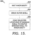
- a method 600 for manufacturing a multi-layer upper for an article of footwear is shown in FIG. 15 .
- the method includes knitting an inner booty, as shown at block 602.
- the inner booty of block 602 in some aspects has the characteristics described above with respect to inner booty 12.
- the method continues at block 604 by braiding an outer braided shell.
- the outer braded shell of block 604 in some aspects, has the characteristics described above with respect to outer braided shell 14.
- the method 600 continues at block 606 by coating selected locations of the outer braided shell, to couple the outer braided shell to the inner booty at the selected locations (leaving other locations of the outer braided shell uncoated, and uncoupled to the inner booty).
- the coating is a spray coating such as coating 503 described above with reference to FIGS. 11-14 .
- an exemplary clause 4 may indicate the method/apparatus of any of clauses 1 through 3, which is intended to be interpreted such that features of clause 1 and clause 4 may be combined, elements of clause 2 and clause 4 may be combined, elements of clause 3 and 4 may be combined, elements of clauses 1, 2, and 4 may be combined, elements of clauses 2, 3, and 4 may be combined, elements of clauses 1, 2, 3, and 4 may be combined, and/or other variations.
- the terminology “any of clauses” or similar variations of said terminology is intended to include “any one of clauses” or other variations of such terminology, as indicated by some of the examples provided above.
- An article of footwear with an upper having a toe end, a heel end, a medial side, and a lateral side, the upper comprising an inner booty extending from the heel end to the toe end, having an opening for a foot in the as worn condition; an outer braided shell extending at least partially around the inner booty; and a layer coupling the outer braided shell to the inner booty in selected locations of the upper, leaving the outer braided shell uncoupled from the inner booty in other locations of the upper.
- the layer is a thermoplastic layer disposed over the outer braided shell in a first portion of the selected locations and wherein the thermoplastic layer is disposed between the outer braided shell and the inner booty in a second portion of the selected locations.
- Clause 7 The article of footwear of any of the clauses, wherein the weft knit is a circular knit.
- Clause 10 The article of footwear of any of the clauses, wherein the weft knit is a flat knit.
- Clause 11 The article of footwear of any of the clauses, wherein the layer is a coating covering the selected locations of the upper.
- Clause 12 The article of footwear of any of the clauses, wherein the coating and the outer braided shell create a textured surface at the selected locations of the upper.
- Clause 13 The article of footwear of any of the clauses, wherein the article of footwear has a bottom and wherein the coating covers at least a portion of the bottom of the article of footwear.
- Clause 14 The article of footwear of any of the clauses, wherein the coating covers the entirety of the bottom of the article of footwear.
Landscapes
- Engineering & Computer Science (AREA)
- Chemical & Material Sciences (AREA)
- Materials Engineering (AREA)
- Mechanical Engineering (AREA)
- Footwear And Its Accessory, Manufacturing Method And Apparatuses (AREA)
- Braiding, Manufacturing Of Bobbin-Net Or Lace, And Manufacturing Of Nets By Knotting (AREA)
Abstract
Description
- Aspects herein relate to a footwear upper having a braided structure with an outer coating that covers at least a portion of the braided upper.
- Traditional shoes are often made from textiles or materials that have uppers that are cut to a desired shape and stitched together. Newer methods also now include forming footwear uppers from a knitted textile. Still newer methods involve braiding a material for use as the footwear upper. Aspects herein relate to braided structures for footwear that are selectively coated in some areas.
- This Summary provides a high-level overview of the disclosure and introduces a selection of concepts that are further described in the Detailed Description below. This Summary is not intended to identify key features or essential features of the claimed subject matter, nor is it intended to be used as an aid in isolation to determine the scope of the claimed subject matter.
- Aspects herein generally relate to a multi-layer upper for an article of footwear. The upper has a medial side and a lateral side, and a toe end and a heel end. The upper has an inner booty, at least partially surrounded by an outer braided shell, made from a number of yarns that are braided together. In selected locations, a coating covers portions of the outer braided shell. In some aspects, this coating creates a textured surface. In some aspects this textured surface covers at least a portion of the bottom of the article of footwear.
- Aspects herein are described in detail below with reference to the attached drawing figures, wherein:
-
FIG. 1 depicts an article of footwear, in accordance with aspects herein; -
FIG. 2 depicts a cross-section taken along line 2-2 ofFIG. 1 ; -
FIG. 3 depicts a cross-section taken along line 3-3 ofFIG. 1 ; -
FIG. 4 depicts an enlarged partial view of theencircled region 4 inFIG. 2 ; -
FIG. 5 depicts an enlarged partial view of theencircled region 5 inFIG. 2 ; -
FIG. 6 depicts a schematic view of an exemplary braiding machine; -
FIG. 7 depicts a perspective view of an exemplary braiding machine, illustrating the carriages and rotor metals; -
FIG. 8 depicts a view similar toFIG. 7 , but with the rotor metals moving the carriages; -
FIG. 9 depicts a view similar toFIG. 8 , but showing the completion of the exemplary movement ofFIG. 8 ; -
FIG. 10 depicts an exemplary method for making the article ofFIGS. 1-5 ; -
FIG. 11 depicts an article of footwear, in accordance with aspects herein; -
FIG. 12 depicts a cross-sectional view taken along line 12-12 ofFIG. 11 ; -
FIG. 13 depicts a cross-sectional view taken along line 13-13 ofFIG. 11 ; -
FIG. 14 is an enlarged view of the encircled region ofFIG. 12 labeled 14; and -
FIG. 15 depicts an exemplary method for making the article ofFIGS. 11-14 . - Aspects herein provide a multi-layer upper for an article of footwear. The upper has a medial side and a lateral side, and a toe end and a heel end. The upper has an inner knit booty, at least partially surrounded by an outer braided shell, made from a number of yarns that are braided together. In selected locations, the inner knit booty and the outer braided shell are coupled together with a thermoplastic material disposed over the outer braided shell. In other selected locations, the inner booty and the outer braided shell may be coupled together with a thermoplastic material disposed between the outer braided shell and the inner booty. In selected locations, a coating covers portions of the outer braided shell. In some aspects, this coating creates a textured surface. In some aspects this textured surface covers at least a portion of the bottom of the article of footwear.
- An article of
footwear 10 is shown inFIG. 1 with a multi-layer upper having aninner booty 12, and an outerbraided shell 14. In one aspect, theinner booty 12 is knitted. In one aspect, theinner booty 12 is formed in a circular knitting process. An exemplary circular knitted upper can be formed as disclosed inU.S. Patent 6,931,762, issued on August 23, 2005 , the disclosure of which is hereby incorporated by reference.Inner booty 12 is formed primarily from multiple yarns that are mechanically manipulated through an interlooping process to produce a unitary structure. Various interlooping techniques are available for mechanically manipulating yarn intoinner booty 12. In general, however, interlooping involves the formation of a plurality of rows and columns of intermeshed loops, which are conventionally referred to as courses and wales. Knitting is generally recognized as being the most common method of interlooping. The configuration ofinner booty 12 is selected to generally conform to the shape of the foot. In some aspects, the knitting process that producesinner booty 12 forms a plurality of sections, each section being specifically located, knit in a specific manner, and knit with a specific type of yarn to provide each section with different physical properties. The knit can be a warp knit, or a weft knit, in some aspect. In order to provide the stretch and recovery properties forinner booty 12, a yarn that incorporates an elastane fiber may be utilized. Elastane fibers are available from E.I. duPont de Nemours Company under the LYCRA trademark. Such fibers may have the configuration of covered LYCRA, wherein the fiber includes a LYCRA core that is surrounded by a nylon sheath. Other fibers or filaments exhibiting elastic properties may also be utilized ininner booty 12. - Yarn is defined as an assembly having a substantial length and relatively small cross-section that is formed of at least one filament or a plurality of fibers. Fibers have a relatively short length and require spinning or twisting processes to produce a yarn of suitable length for use in an interlooping process. Common examples of fibers are cotton and wool. Filaments, however, have an indefinite length and may merely be combined with other filaments to produce a yarn suitable for use in an interlooping process. Modern filaments include a plurality of synthetic materials such as rayon, nylon, polyester, and acrylic. Yarn may be formed of a single filament (conventionally referred to as a monofilament yarn) or a plurality of individual filaments. Yarn may also be formed of separate filaments formed of different materials, or the yarn may be formed of filaments that are each formed of two or more different materials. Similar concepts also apply to yarns formed from fibers. Accordingly, yarns may have a variety of configurations that generally conform to the definition provided above. The characteristics of the various yarns selected for
inner booty 12 depend primarily upon the materials that form the various filaments and fibers. Cotton, for example, provides a soft hand, natural aesthetics, and biodegradability. Elastane fibers, as discussed above, provide substantial stretch and recoverability. Rayon provides high luster and moisture absorption. Wool also provides high moisture absorption, in addition to insulating properties. Polytetrafluoroethylene coatings may provide a low friction contact between the textile and the skin, thereby limiting the formation of blisters. Nylon is a durable and abrasion-resistant material with high strength. Finally, polyester is a hydrophobic material that also provides relatively high durability. Accordingly, the materials comprising the yarn may be selected to impart a variety of physical properties toinner booty 12. The physical properties may include, for example, strength, stretch, support, stiffness, recovery, fit, and form. - A narrow-tube circular knitting machine may be utilized to manufacture
inner booty 12. An example of a circular knitting machine that may be utilized to forminner booty 12 is discussed in earlier-referenced and incorporatedU.S. Patent 6,931,762 . In general, circular knitting machines form a tube-like structure. Theknit booty 12 can be knitted to shape (somewhat tubular, corresponding to the shape of a foot), or can be cut-and-sewn from the circular knit. In another aspect, theknit booty 12 can be made of a flat knit, and again can either be knitted to shape or can be cut-and-sewn from a flat knit material. In some aspects, thebooty 12 can be made from a warp knit, weft knit or circular knit material. - The
outer braided shell 14 is disposed above, or on top of, theinner booty 12. As best seen inFIGS. 2 and 3 ,outer braided shell 14 extends from under theinner booty 12, where it is sandwiched between theinner booty 12 and an outsole/midsole structure 16. In some aspects,outer braided shell 14 is also formed as a tube, and generally surrounds inner booty 12 (going completely underinner booty 12 from one side to the other, as viewed, for example inFIG. 3 ). Outer braidedshell 14, in some aspects has an open throat area 18 (FIG. 1 ), provided withlaces 20. In addition,outer braided shell 14, has anopen ankle area 22, corresponding to the opening ininner booty 12, used to allow a user's foot to access the footwear. In some aspects, the edges of thethroat area 18 andankle area 22 may be provided with a reinforcingband 24.Band 24 can be provided, for example, by a higher-density of braid, an overlay, or other reinforcing structure. - In some areas, the
outer braided shell 14 is not coupled toinner booty 12, such as the area generally mid-foot indicated byarrow 30. In this area, theouter braided shell 14 can move independently of theinner booty 12. In this area, as shown inFIG. 3 ,outer braided shell 14 is retained relative toinner booty 12 only at the lower edge, where it is sandwiched between theinner booty 12 and the outsole/midsole structure 16. Note that a separate midsole and outsole could be provided. For purposes of this disclosure, the nature of the outsole/midsole structure 16 can vary greatly, and so is shown somewhat schematically. - In other areas, the
outer braided shell 14 is coupled to theinner booty 12, such as in the heel area indicated byarrow 32 or the toe box area indicated byarrow 34. As best seen inFIGS. 2 and 4 , in one area,toe box area 34 includes a layer ofskin 36 that is disposed over theouter braided shell 14. Theskin 36 is, in some aspects, a thermoplastic material, such as a thermoplastic polymeric composition. In such aspects, the thermoplastic polymeric composition can include one or more of polyurethanes (such as TPU), polyamides, polyolefins, or nylons that transition when thermoformed. As used herein, "thermoforming" refers to a process for turning a thermoplastic composition from a solid state to a softened or liquid state when subjected to certain temperatures at or above its melting point and then transitions back to the solid state when cooled. In such aspects, the thermoplastic material in this portion of thetoe box area 34 can provide additional stability and rigidity, as well as function as a moisture barrier. Asimilar skin 36 is disposed over theheel area 32 to couple theinner booty 12 to theouter braided shell 14 in selected portions of theheel area 32. When transformed by heat, theskin 36 penetrates through openings in theouter braided shell 14 and adheres to both theouter braided shell 14 and the portions of theinner booty 12, coupling theinner booty 12 to theouter braided shell 14. In some aspects, theskin 36 will have an outer texture formed by the braids in theouter braided shell 14. As best seen inFIGS. 2 and 5 , in onetoe box area 38, alayer 40 is disposed between outerbraided shell 14 and inner booty 12 (as opposed to being disposed over theouter braided shell 14 as discussed above). Thelayer 40, in some aspects, can be formed of the same material asskin 36, or can be formed of a different hot-melt material. The melt temperature of bothskin 36 andlayer 38 is lower than the yarns used ininner booty 12 andouter braided shell 14. Withlayer 40 between theinner booty 12 and theouter layer 14, a different aesthetic is achieved, and performance characteristics may also be varied. - In general, the braiding for
outer braided shell 14 is a process of interlacing or interweaving three or more yarns diagonally to a product axis in order to obtain a thicker, wider, or stronger product or in order to cover (overbraid) some profile. Interlacing diagonally means that the yarns make an angle with the product axis, which can be between 1° and 89° but is usually in the range of 30° - 80°. This angle is called the braiding angle. Braids can be linear products (ropes), hollow tubular shells, or solid structures (one, two, or three-dimensional textiles) with constant or variable cross-sections, and of closed or open appearance. - As used herein, the yarns used for braiding may be formed of different materials having different properties. The properties that a particular yarn will impart to an area of a braided component partially depend upon the materials that form the yarn. Cotton, for example, provides a softer product, natural aesthetics, and biodegradability. Elastane and stretch polyester each provide substantial stretch and recovery, with stretch polyester also providing recyclability. Rayon provides high luster and moisture absorption. Wool also provides high moisture absorption, in addition to insulating properties and biodegradability. Nylon is a durable and abrasion-resistant material with relatively high strength. Polyester is a hydrophobic material that also provides relatively high durability. In addition to materials, other aspects of the yarn selected for formation of a braided component may affect the properties of the braided component. For example, a yarn may be a monofilament or a multifilament. The yarn may also include separate filaments that are each formed of different materials. In addition, the yarn may include filaments that are each formed of two or more different materials, such as a bicomponent yarn with filaments having a sheath-core configuration or two halves formed of different materials.
- As stated above, braided structures can be formed as tubular braids on a braiding machine, such as a radial, axial, or lace braiding machine. One example of a lace braiding machine can be found in Ichikawa,
EP 1 486 601, granted May 9, 2007 , entitled "Torchon Lace Machine," andEP No. 2 657 384, published Oct. 30, 2013 , entitled "Torchon Lace Machine," the entireties of which are hereby incorporated by reference. The upper portion of anexemplary braiding machine 100 is shown inFIG. 6 .Braiding machine 100 includes a plurality ofspools 112. In some embodiments, thespools 112 carry theyarn 114 selected for braiding. Theyarns 114 from individual spools are selectively interlaced or intertwined with one another by thebraiding machine 100. This interlacing or intertwining of strands forms abraided structure 116, as further described below. Each of thespools 112 is supported and constrained by atrack 118 about the circumference of thebraiding machine 100. Eachspool 112 has a tensioner 120 (shown schematically inFIG. 6 ) that operates, along with aroller 122, to maintain a desired tension in theyarns 114 and thebraided structure 116. As theyarns 114 extend upwardly, they pass through abraid ring 124 that is generally considered the braiding point. The braiding point is defined as the point or area whereyarns 114 consolidate to formbraid structure 116. At ornear ring 124, the distance betweenyarns 114 fromdifferent spools 112 diminishes. As the distance betweenyarns 114 is reduced, theyarns 114 intermesh or braid with one another in a tighter fashion and are pulled linearly byroller 122. - As best seen in
FIG. 7 , eachspool 112 is carried and supported by acarriage 126. Eachspool 112 is movable about the circumference of thetrack 118 byrotor metals 128. As described on the Torchon Lace Machine referenced previously, and disclosed inEP 1 486 601 , each of therotor metals 128 can be moved clockwise or counterclockwise. In contrast to radial braiding machines or fully non-jacquard machines, in a lace braiding machine, each rotor metal is not intermeshed with the adjacent rotor metal. Instead, eachrotor metal 128 may be selectively independently movable. As can be seen by comparingFIG. 7 to FIG. 9 , as therotor metals 128 rotate, they move thecarriages 126, and thus thespools 112 supported on thecarriages 126, by moving them about the circumference of thetrack 118. Thebraiding machine 100 is programmable such that theindividual rotor metals 128 rotate thecarriages 126, and thus thespools 112, to move them about the circumference of thetrack 118. As anindividual spool 112 moves relative to anadjacent spool 112, theyarns 114 carried on thespools 112 interweave to create a desired braid pattern. The movement ofspools 112 may be preprogrammed to form particular shapes, designs, and thread densities of a braided component or portions of a braided component. By varying the rotation and location ofindividual spools 112, various braid configurations may be formed. Such an exemplary braiding machine may form intricate braid configurations including both jacquard and non-jacquard braid configurations or geometries. Such configurations and geometries offer design possibilities beyond those offered by other textiles, such as knitting. - In some aspects, the size of
braiding machine 100 may be varied. It should be understood that thebraiding machine 100 shown and described is for illustrative purposes only. In some aspects, braidingmachine 100 may be able to accept 144 carriages, although other sizes of braiding machines, carrying different numbers of carriages and spools, is possible and is within the scope of this disclosure. By varying the number of carriages and spools within a braiding machine, the density of the braided structure as well as the size of the braided component may be altered. - A method 400 for manufacturing a multi-layer upper for an article of footwear is shown in
FIG. 10 . The method includes knitting an inner booty, as shown atblock 402. The inner booty ofblock 402 in some aspects has the characteristics described above with respect toinner booty 12. The method continues atblock 404 by braiding an outer braided shell. The outer braded shell ofblock 404, in some aspects, has the characteristics described above with respect toouter braided shell 14. In some aspects, the method 400 continues atblock 406 by placing a thermoplastic material over the outer braided shell in selected locations. Similarly, in some aspects, the method 400 includes, as shown atblock 408, placing a thermoplastic layer between the inner booty and the outer braided shell in selected locations. As shown atblock 410, the method continues by heating the thermoplastic layers ofblocks - In other aspects, as shown in
FIGs. 11-14 , a braided article offootwear 500 may include theinner booty 12, constructed as described above, along with thebraided shell 14, also constructed as described above. In one aspect, thebraided shell 14 is covered with acoating 502 in selected areas of the braided footwear upper 500. As shown inFIG. 11 , thecoating 502 may be applied in theheel area 32 and thetoe box area 34. In addition, in some aspects, as shown inFIGs. 12-14 , thecoating 502 covers at least part of the bottom 504, and in some aspects covers the entire bottom 504 (as best seen inFIG. 12 ). In some aspects, coating 502 is applied as a spray coating. Thecoating 502 can include one or more of polyurethanes (such as TPU), polyamides, polyolefins, or nylons. In such aspects, thecoating 502 can provide additional stability and rigidity, as well as function as a moisture barrier. Further, thecoating 502, in cooperation with thebraided shell 14, provides a traction surface as the textured surface created by thebraided shell 14 is preserved by thecoating 502, In other words, in some aspects, coating 502 does not provide a smooth surface overbraided shell 14 in at least some areas. Instead, the yarns of thebraided shell 14 create atextured surface 506 as best seen inFIG. 14 . In some aspects, thistextured surface 506 forms the outer surface of the braided article offootwear 500, such as atbottom 504. In some aspects, thecoating 502 penetrates through openings in theouter braided shell 14 and adheres to both theouter braided shell 14 and the portions of theinner booty 12, coupling theinner booty 12 to theouter braided shell 14. As best seen inFIG. 13 and 14 , in some aspects, the braided article of footwear also includes aninsole 508 that may provide added cushioning and comfort. - A method 600 for manufacturing a multi-layer upper for an article of footwear is shown in
FIG. 15 . The method includes knitting an inner booty, as shown atblock 602. The inner booty ofblock 602 in some aspects has the characteristics described above with respect toinner booty 12. The method continues atblock 604 by braiding an outer braided shell. The outer braded shell ofblock 604, in some aspects, has the characteristics described above with respect toouter braided shell 14. In some aspects, the method 600 continues atblock 606 by coating selected locations of the outer braided shell, to couple the outer braided shell to the inner booty at the selected locations (leaving other locations of the outer braided shell uncoated, and uncoupled to the inner booty). In some aspects, the coating is a spray coating such as coating 503 described above with reference toFIGS. 11-14 . - Many different arrangements of the various components depicted, as well as components not shown, are possible without departing from the spirit and scope of the present disclosure. Embodiments of the present disclosure have been described with the intent to be illustrative rather than restrictive. Alternative embodiments will become apparent to those skilled in the art that do not depart from its scope. A skilled artisan may develop alternative means of implementing the aforementioned improvements without departing from the scope of the present disclosure.
- It will be understood that certain features and subcombinations are of utility and may be employed without reference to other features and subcombinations. This is contemplated by and is within the scope of the claims.
- While specific elements and steps are discussed in connection to one another, it is understood that any element and/or steps provided herein is contemplated as being combinable with any other elements and/or steps regardless of explicit provision of the same while still being within the scope provided herein. Since many possible embodiments may be made of the disclosure without departing from the scope thereof, it is to be understood that all matter herein set forth or shown in the accompanying drawings is to be interpreted as illustrative and not in a limiting sense.
- From the foregoing, it will be seen that this invention is one well-adapted to attain all the ends and objects hereinabove set forth together with other advantages which are obvious and which are inherent to the structure.
- It will be understood that certain features and subcombinations are of utility and may be employed without reference to other features and subcombinations. This is contemplated by and is within the scope of the claims.
- As used herein and in connection with the claims listed hereinafter, the terminology "any of clauses" or similar variations of said terminology is intended to be interpreted such that features of claims/clauses may be combined in any combination. For example, an
exemplary clause 4 may indicate the method/apparatus of any of clauses 1 through 3, which is intended to be interpreted such that features of clause 1 andclause 4 may be combined, elements ofclause 2 andclause 4 may be combined, elements ofclause clauses clauses clauses - The following clauses are aspects contemplated herein.
- Clause 1. An article of footwear with an upper having a toe end, a heel end, a medial side, and a lateral side, the upper comprising an inner booty extending from the heel end to the toe end, having an opening for a foot in the as worn condition; an outer braided shell extending at least partially around the inner booty; and a layer coupling the outer braided shell to the inner booty in selected locations of the upper, leaving the outer braided shell uncoupled from the inner booty in other locations of the upper.
-
Clause 2. The article of footwear of any of the clauses, wherein the layer is a thermoplastic layer disposed over the outer braided shell in the selected locations. -
Clause 3. The article of footwear of any of the clauses, wherein the layer is a thermoplastic layer disposed between the outer braided shell and the inner booty in the selected locations. -
Clause 4. The article of footwear of any of the clauses, wherein the layer is a thermoplastic layer disposed over the outer braided shell in a first portion of the selected locations and wherein the thermoplastic layer is disposed between the outer braided shell and the inner booty in a second portion of the selected locations. -
Clause 5. The article of footwear of any of the clauses, wherein the booty is made from a warp knit material. - Clause 6. The article of footwear of any of the clauses, wherein the booty is made from a weft knit material.
- Clause 7. The article of footwear of any of the clauses, wherein the weft knit is a circular knit.
- Clause 8. The article of footwear of any of the clauses, wherein the booty is cut-and-sewn to shape.
- Clause 9. The article of footwear of any of the clauses, wherein the booty is knitted to shape.
-
Clause 10. The article of footwear of any of the clauses, wherein the weft knit is a flat knit. - Clause 11. The article of footwear of any of the clauses, wherein the layer is a coating covering the selected locations of the upper.
-
Clause 12. The article of footwear of any of the clauses, wherein the coating and the outer braided shell create a textured surface at the selected locations of the upper. -
Clause 13. The article of footwear of any of the clauses, wherein the article of footwear has a bottom and wherein the coating covers at least a portion of the bottom of the article of footwear. -
Clause 14. The article of footwear of any of the clauses, wherein the coating covers the entirety of the bottom of the article of footwear. - Further features, aspects and embodiments are provided below in the following items:
- Item 1. An article of footwear with an upper having a toe end, a heel end, a medial side, and a lateral side, the upper comprising: an inner booty extending from the heel end to the toe end, having an opening for a foot in the as worn condition; an outer braided shell extending at least partially around the inner booty; and a layer coupling the outer braided shell to the inner booty in selected locations of the upper, leaving the outer braided shell uncoupled from the inner booty in other locations of the upper.
-
Item 2. The article of footwear of item 1, wherein the layer is a thermoplastic layer disposed over the outer braided shell in the selected locations. -
Item 3. The article of footwear of item 1, wherein the layer is a thermoplastic layer disposed between the outer braided shell and the inner booty in the selected locations. -
Item 4. The article of footwear of item 1, wherein the layer is a thermoplastic layer disposed over the outer braided shell in a first portion of the selected locations and wherein the thermoplastic layer is disposed between the outer braided shell and the inner booty in a second portion of the selected locations. -
Item 5. The article of footwear of item 1, wherein the booty is made from a warp knit material. - Item 6. The article of footwear of item 1, wherein the booty is made from a weft knit material.
- Item 7. The article of footwear of item 6, wherein the weft knit is a circular knit.
- Item 8. The article of footwear of item 7, wherein the booty is cut-and-sewn to shape.
- Item 9. The article of footwear of item 7, wherein the booty is knitted to shape.
-
Item 10. The article of footwear of item 6, wherein the weft knit is a flat knit. - Item 11. The article of footwear of
item 10, wherein the booty is cut-and-sewn to shape. -
Item 12. The article of footwear ofitem 10, wherein the booty is knitted to shape. -
Item 13. The article of footwear of item 1, wherein the layer is a coating covering the selected locations of the upper. -
Item 14. The article of footwear ofitem 13, wherein the coating and the outer braided shell create a textured surface at the selected locations of the upper. - Item 15. The article of footwear of
item 13, wherein the article of footwear has a bottom and wherein the coating covers at least a portion of the bottom of the article of footwear. -
Item 16. The article of footwear of item 15, wherein the coating covers the entirety of the bottom of the article of footwear. - Item 17. A method of manufacturing an upper for an article of footwear, the upper having a toe end, a heel end, a medial side, and a lateral side, the method comprising: knitting an inner booty that extends from the heel end to the toe end, and that has an opening for a foot in the as worn condition; braiding an outer shell with a shape that extends at least partially around the inner booty; placing a first thermoplastic layer over first selected locations of the outer braided shell, leaving the other locations of the outer braided shell without the thermoplastic layer; and heating the thermoplastic layer to couple the outer braided shell to the inner booty at the first selected locations.
-
Item 18. The method of item 17, further comprising: placing a second thermoplastic layer between second selected locations of the outer braided shell and the inner booty; and heating the second thermoplastic layer to couple the outer braided shell to the inner booty at the second selected locations. - Item 19. A method of manufacturing an upper for an article of footwear, the upper having a toe end, a heel end, a medial side, and a lateral side, the method comprising: knitting an inner booty that extends from the heel end to the toe end, and that has an opening for a foot in the as worn condition; braiding an outer shell with a shape that extends at least partially around the inner booty; coating only selected locations of the outer braided shell, leaving the other locations of the outer braided shell without the coating, to couple the outer braided shell to the inner booty at the selected locations.
-
Item 20. The method of item 19, wherein the coating step comprises a spray coating.
Claims (15)
- A method of manufacturing an upper for an article of footwear, the upper having a toe end, a heel end, a medial side, and a lateral side, the method comprising: knitting an inner booty (12) that extends from the heel end to the toe end, and that has an opening for a foot in the as worn condition; braiding an outer shell (14) with a shape that extends at least partially around the inner booty (12); coating only selected locations of the outer braided shell (14), leaving the other locations of the outer braided shell (14) without the coating (502), to couple the outer braided shell (14) to the inner booty (12) at the selected locations.
- The method of claim 1, wherein the coating step comprises a spray coating (502).
- The method of any one of the preceding claims, wherein the selected locations of the outer braided shell (14) comprise a heel area (32) and/or a toe box area (34).
- The method of any one of the preceding claims, wherein the selected locations of the outer braided shell (14) comprise at least part of a bottom (504), particularly wherein the selected locations of the outer braided shell (14) comprise the entire bottom (504).
- The method of any one of the preceding claims, wherein the coating (502) includes one or more of polyurethanes (such as TPU), polyamides, polyolefins, or nylons.
- The method of any one of the preceding claims, wherein the coating (502), in cooperation with the outer braided shell (14), is configured to provide a traction surface.
- The method of any one of the preceding claims, wherein yarns of the outer braided shell (14) are configured to create a textured surface (506).
- The method of claim 7, wherein the textured surface (506) is arranged to form an outer surface of the article of footwear, particularly wherein the outer surface is a bottom surface (504).
- The method of any one of the preceding claims, further comprising providing an insole (508) configured to provide added cushioning.
- A braided article of footwear (10) with an upper having a toe end, a heel end, a medial side, and a lateral side, the upper comprising:an inner booty (12) extending from the heel end to the toe end, having an opening for a foot in the as worn condition;an outer braided shell (14) extending at least partially around the inner booty (12); anda coating (502) configured to cover the outer braided shell (14) in selected areas of the upper, wherein the coating (502) is arranged to penetrate through openings in the outer braided shell (14) and to adhere to both the outer braided shell (14) and portions of the inner booty (12), coupling the inner booty (12) to the outer braided shell (14).
- The braided article of footwear (10) of claim 10, wherein the selected areas of the upper comprise a heel area (32), a toe box area (34), and/or at least part of a bottom (504).
- The braided article of footwear (10) of any one of claims 10 to 11, wherein the coating (502) includes one or more of polyurethanes (such as TPU), polyamides, polyolefins, or nylons.
- The braided article of footwear (10) of any one of claims 10 to 12, wherein the coating (502), in cooperation with the outer braided shell (14), is configured to provide a traction surface.
- The braided article of footwear (10) of any one of claims 10 to 13, wherein yarns of the outer braided shell (14) are configured to create a textured surface (506), wherein, optionally, the textured surface (506) is arranged to form an outer surface of the article of footwear, wherein, optionally, the outer surface is a bottom surface (504).
- The braided article of footwear (10) of any one of claims 10 to 14, further comprising an insole (508).
Applications Claiming Priority (4)
| Application Number | Priority Date | Filing Date | Title |
|---|---|---|---|
| US201762588473P | 2017-11-20 | 2017-11-20 | |
| US16/192,129 US20190150552A1 (en) | 2017-11-20 | 2018-11-15 | Multi-layer braided upper |
| EP18836703.1A EP3687329B1 (en) | 2017-11-20 | 2018-11-16 | Multi-layer braided upper |
| PCT/US2018/061502 WO2019099816A1 (en) | 2017-11-20 | 2018-11-16 | Multi-layer braided upper |
Related Parent Applications (2)
| Application Number | Title | Priority Date | Filing Date |
|---|---|---|---|
| EP18836703.1A Division-Into EP3687329B1 (en) | 2017-11-20 | 2018-11-16 | Multi-layer braided upper |
| EP18836703.1A Division EP3687329B1 (en) | 2017-11-20 | 2018-11-16 | Multi-layer braided upper |
Publications (2)
| Publication Number | Publication Date |
|---|---|
| EP4085780A1 true EP4085780A1 (en) | 2022-11-09 |
| EP4085780B1 EP4085780B1 (en) | 2024-01-31 |
Family
ID=66534752
Family Applications (2)
| Application Number | Title | Priority Date | Filing Date |
|---|---|---|---|
| EP18836703.1A Active EP3687329B1 (en) | 2017-11-20 | 2018-11-16 | Multi-layer braided upper |
| EP22174209.1A Active EP4085780B1 (en) | 2017-11-20 | 2018-11-16 | Multi-layer braided upper |
Family Applications Before (1)
| Application Number | Title | Priority Date | Filing Date |
|---|---|---|---|
| EP18836703.1A Active EP3687329B1 (en) | 2017-11-20 | 2018-11-16 | Multi-layer braided upper |
Country Status (4)
| Country | Link |
|---|---|
| US (1) | US20190150552A1 (en) |
| EP (2) | EP3687329B1 (en) |
| CN (1) | CN111372483B (en) |
| WO (1) | WO2019099816A1 (en) |
Families Citing this family (14)
| Publication number | Priority date | Publication date | Assignee | Title |
|---|---|---|---|---|
| WO2014209596A1 (en) | 2013-06-25 | 2014-12-31 | Nike Innovate C.V. | Article of footwear with braided upper |
| US10863794B2 (en) * | 2013-06-25 | 2020-12-15 | Nike, Inc. | Article of footwear having multiple braided structures |
| US10674791B2 (en) | 2014-12-10 | 2020-06-09 | Nike, Inc. | Braided article with internal midsole structure |
| US9668544B2 (en) | 2014-12-10 | 2017-06-06 | Nike, Inc. | Last system for articles with braided components |
| US20160345675A1 (en) | 2015-05-26 | 2016-12-01 | Nike, Inc. | Hybrid Braided Article |
| US10555581B2 (en) | 2015-05-26 | 2020-02-11 | Nike, Inc. | Braided upper with multiple materials |
| US11103028B2 (en) | 2015-08-07 | 2021-08-31 | Nike, Inc. | Multi-layered braided article and method of making |
| CN110691530B (en) * | 2017-05-30 | 2022-03-01 | 耐克创新有限合伙公司 | Mechanical lock sole structure for knitted footwear |
| US11051573B2 (en) | 2017-05-31 | 2021-07-06 | Nike, Inc. | Braided articles and methods for their manufacture |
| US10806210B2 (en) | 2017-05-31 | 2020-10-20 | Nike, Inc. | Braided articles and methods for their manufacture |
| US11202483B2 (en) | 2017-05-31 | 2021-12-21 | Nike, Inc. | Braided articles and methods for their manufacture |
| USD918546S1 (en) * | 2019-08-16 | 2021-05-11 | Nike, Inc. | Shoe |
| CN113832593A (en) * | 2021-07-19 | 2021-12-24 | 信泰(福建)科技有限公司 | A multi-layer knitted shoe upper |
| JP2024530174A (en) * | 2021-08-13 | 2024-08-16 | プーマ エス イー | Systems and methods for manufacturing footwear |
Citations (7)
| Publication number | Priority date | Publication date | Assignee | Title |
|---|---|---|---|---|
| EP1486601A1 (en) | 2003-06-10 | 2004-12-15 | Ichikawa Tekko Co., Ltd. | Torchon lace machine |
| US6931762B1 (en) | 2002-12-18 | 2005-08-23 | Nike, Inc. | Footwear with knit upper and method of manufacturing the footwear |
| US20070022627A1 (en) * | 2005-07-29 | 2007-02-01 | Nike, Inc. | Footwear structure with textile upper member |
| EP2657384A1 (en) | 2010-12-22 | 2013-10-30 | Ichikawa Iron Works Co., Ltd. | Torchon lace machine |
| US20150282564A1 (en) * | 2014-04-08 | 2015-10-08 | Nike, Inc. | Components for articles of footwear including lightweight, selectively supported textile components |
| WO2016093961A1 (en) * | 2014-12-10 | 2016-06-16 | Nike Innovate C.V. | Article of footwear having multiple braided structures |
| US20170035149A1 (en) * | 2015-08-07 | 2017-02-09 | Nike, Inc. | Multi-Layered Braided Article And Method Of Making |
Family Cites Families (11)
| Publication number | Priority date | Publication date | Assignee | Title |
|---|---|---|---|---|
| US7793434B2 (en) * | 2004-09-03 | 2010-09-14 | Nike, Inc. | Article of footwear having an upper with a structured intermediate layer |
| DE102006010007A1 (en) * | 2006-03-03 | 2007-09-06 | W.L. Gore & Associates Gmbh | Water vapor permeable composite shoe sole comprises openings closed with a barrier material supported by a stabilizing system of crosspieces |
| US8051585B2 (en) * | 2008-11-06 | 2011-11-08 | Nike, Inc. | Article of footwear comprising a plurality of strips |
| US8578632B2 (en) * | 2010-07-19 | 2013-11-12 | Nike, Inc. | Decoupled foot stabilizer system |
| US8839532B2 (en) * | 2011-03-15 | 2014-09-23 | Nike, Inc. | Article of footwear incorporating a knitted component |
| US9861160B2 (en) * | 2012-11-30 | 2018-01-09 | Nike, Inc. | Article of footwear incorporating a knitted component |
| US20140373389A1 (en) * | 2013-06-25 | 2014-12-25 | Nike, Inc. | Braided Upper With Overlays For Article Of Footwear |
| EP2839755B1 (en) * | 2013-08-23 | 2020-03-25 | Adidas AG | Shoe upper and shoe comprising such shoe upper |
| US9192204B1 (en) * | 2014-09-30 | 2015-11-24 | Nike, Inc. | Article of footwear upper incorporating a textile component with tensile elements |
| US10716354B2 (en) * | 2017-07-13 | 2020-07-21 | Under Armour, Inc. | Braided article and method of making |
| US20200146390A1 (en) * | 2017-07-17 | 2020-05-14 | W. L. Gore & Associates Gmbh | Footwear |
-
2018
- 2018-11-15 US US16/192,129 patent/US20190150552A1/en not_active Abandoned
- 2018-11-16 WO PCT/US2018/061502 patent/WO2019099816A1/en not_active Ceased
- 2018-11-16 CN CN201880075116.8A patent/CN111372483B/en active Active
- 2018-11-16 EP EP18836703.1A patent/EP3687329B1/en active Active
- 2018-11-16 EP EP22174209.1A patent/EP4085780B1/en active Active
Patent Citations (7)
| Publication number | Priority date | Publication date | Assignee | Title |
|---|---|---|---|---|
| US6931762B1 (en) | 2002-12-18 | 2005-08-23 | Nike, Inc. | Footwear with knit upper and method of manufacturing the footwear |
| EP1486601A1 (en) | 2003-06-10 | 2004-12-15 | Ichikawa Tekko Co., Ltd. | Torchon lace machine |
| US20070022627A1 (en) * | 2005-07-29 | 2007-02-01 | Nike, Inc. | Footwear structure with textile upper member |
| EP2657384A1 (en) | 2010-12-22 | 2013-10-30 | Ichikawa Iron Works Co., Ltd. | Torchon lace machine |
| US20150282564A1 (en) * | 2014-04-08 | 2015-10-08 | Nike, Inc. | Components for articles of footwear including lightweight, selectively supported textile components |
| WO2016093961A1 (en) * | 2014-12-10 | 2016-06-16 | Nike Innovate C.V. | Article of footwear having multiple braided structures |
| US20170035149A1 (en) * | 2015-08-07 | 2017-02-09 | Nike, Inc. | Multi-Layered Braided Article And Method Of Making |
Also Published As
| Publication number | Publication date |
|---|---|
| EP3687329B1 (en) | 2022-09-28 |
| WO2019099816A4 (en) | 2019-07-11 |
| EP3687329A1 (en) | 2020-08-05 |
| WO2019099816A1 (en) | 2019-05-23 |
| CN111372483A (en) | 2020-07-03 |
| CN111372483B (en) | 2021-10-22 |
| EP4085780B1 (en) | 2024-01-31 |
| US20190150552A1 (en) | 2019-05-23 |
Similar Documents
| Publication | Publication Date | Title |
|---|---|---|
| EP4085780B1 (en) | Multi-layer braided upper | |
| EP4008821B1 (en) | Braided article of footwear incorporating flat yarn | |
| CN108378470B (en) | Multilayer woven article and method of manufacture | |
| EP3665320B1 (en) | Multiple layer knitted components having multi-bed area | |
| EP4019684B1 (en) | Method of forming a braided shoe article | |
| CN110662861B (en) | Braided article and method for producing same | |
| CN110678597B (en) | Braided article and method for producing same | |
| EP3631069B1 (en) | Braided articles and methods for their manufacture | |
| EP3810839B1 (en) | Braided footwear with integrated laces and methods for their manufacture | |
| EP3583260B1 (en) | Braided double layer tube for single layer footwear upper | |
| US20180343960A1 (en) | Method of manufacturing a bi-axial braided article of footwear |
Legal Events
| Date | Code | Title | Description |
|---|---|---|---|
| PUAI | Public reference made under article 153(3) epc to a published international application that has entered the european phase |
Free format text: ORIGINAL CODE: 0009012 |
|
| STAA | Information on the status of an ep patent application or granted ep patent |
Free format text: STATUS: THE APPLICATION HAS BEEN PUBLISHED |
|
| AC | Divisional application: reference to earlier application |
Ref document number: 3687329 Country of ref document: EP Kind code of ref document: P |
|
| AK | Designated contracting states |
Kind code of ref document: A1 Designated state(s): AL AT BE BG CH CY CZ DE DK EE ES FI FR GB GR HR HU IE IS IT LI LT LU LV MC MK MT NL NO PL PT RO RS SE SI SK SM TR |
|
| STAA | Information on the status of an ep patent application or granted ep patent |
Free format text: STATUS: REQUEST FOR EXAMINATION WAS MADE |
|
| 17P | Request for examination filed |
Effective date: 20230504 |
|
| RBV | Designated contracting states (corrected) |
Designated state(s): AL AT BE BG CH CY CZ DE DK EE ES FI FR GB GR HR HU IE IS IT LI LT LU LV MC MK MT NL NO PL PT RO RS SE SI SK SM TR |
|
| P01 | Opt-out of the competence of the unified patent court (upc) registered |
Effective date: 20230515 |
|
| GRAP | Despatch of communication of intention to grant a patent |
Free format text: ORIGINAL CODE: EPIDOSNIGR1 |
|
| STAA | Information on the status of an ep patent application or granted ep patent |
Free format text: STATUS: GRANT OF PATENT IS INTENDED |
|
| RIC1 | Information provided on ipc code assigned before grant |
Ipc: A43B 5/02 20060101ALI20230822BHEP Ipc: A43B 23/02 20060101ALI20230822BHEP Ipc: A43B 1/04 20220101AFI20230822BHEP |
|
| INTG | Intention to grant announced |
Effective date: 20230925 |
|
| GRAS | Grant fee paid |
Free format text: ORIGINAL CODE: EPIDOSNIGR3 |
|
| GRAA | (expected) grant |
Free format text: ORIGINAL CODE: 0009210 |
|
| STAA | Information on the status of an ep patent application or granted ep patent |
Free format text: STATUS: THE PATENT HAS BEEN GRANTED |
|
| AC | Divisional application: reference to earlier application |
Ref document number: 3687329 Country of ref document: EP Kind code of ref document: P |
|
| AK | Designated contracting states |
Kind code of ref document: B1 Designated state(s): AL AT BE BG CH CY CZ DE DK EE ES FI FR GB GR HR HU IE IS IT LI LT LU LV MC MK MT NL NO PL PT RO RS SE SI SK SM TR |
|
| REG | Reference to a national code |
Ref country code: GB Ref legal event code: FG4D Ref country code: CH Ref legal event code: EP |
|
| REG | Reference to a national code |
Ref country code: DE Ref legal event code: R096 Ref document number: 602018064872 Country of ref document: DE |
|
| REG | Reference to a national code |
Ref country code: IE Ref legal event code: FG4D |
|
| REG | Reference to a national code |
Ref country code: LT Ref legal event code: MG9D |
|
| REG | Reference to a national code |
Ref country code: NL Ref legal event code: MP Effective date: 20240131 |
|
| PG25 | Lapsed in a contracting state [announced via postgrant information from national office to epo] |
Ref country code: IS Free format text: LAPSE BECAUSE OF FAILURE TO SUBMIT A TRANSLATION OF THE DESCRIPTION OR TO PAY THE FEE WITHIN THE PRESCRIBED TIME-LIMIT Effective date: 20240531 |
|
| PG25 | Lapsed in a contracting state [announced via postgrant information from national office to epo] |
Ref country code: LT Free format text: LAPSE BECAUSE OF FAILURE TO SUBMIT A TRANSLATION OF THE DESCRIPTION OR TO PAY THE FEE WITHIN THE PRESCRIBED TIME-LIMIT Effective date: 20240131 |
|
| PG25 | Lapsed in a contracting state [announced via postgrant information from national office to epo] |
Ref country code: GR Free format text: LAPSE BECAUSE OF FAILURE TO SUBMIT A TRANSLATION OF THE DESCRIPTION OR TO PAY THE FEE WITHIN THE PRESCRIBED TIME-LIMIT Effective date: 20240501 |
|
| REG | Reference to a national code |
Ref country code: AT Ref legal event code: MK05 Ref document number: 1653233 Country of ref document: AT Kind code of ref document: T Effective date: 20240131 |
|
| PG25 | Lapsed in a contracting state [announced via postgrant information from national office to epo] |
Ref country code: HR Free format text: LAPSE BECAUSE OF FAILURE TO SUBMIT A TRANSLATION OF THE DESCRIPTION OR TO PAY THE FEE WITHIN THE PRESCRIBED TIME-LIMIT Effective date: 20240131 Ref country code: RS Free format text: LAPSE BECAUSE OF FAILURE TO SUBMIT A TRANSLATION OF THE DESCRIPTION OR TO PAY THE FEE WITHIN THE PRESCRIBED TIME-LIMIT Effective date: 20240430 Ref country code: NL Free format text: LAPSE BECAUSE OF FAILURE TO SUBMIT A TRANSLATION OF THE DESCRIPTION OR TO PAY THE FEE WITHIN THE PRESCRIBED TIME-LIMIT Effective date: 20240131 |
|
| PG25 | Lapsed in a contracting state [announced via postgrant information from national office to epo] |
Ref country code: ES Free format text: LAPSE BECAUSE OF FAILURE TO SUBMIT A TRANSLATION OF THE DESCRIPTION OR TO PAY THE FEE WITHIN THE PRESCRIBED TIME-LIMIT Effective date: 20240131 |
|
| PG25 | Lapsed in a contracting state [announced via postgrant information from national office to epo] |
Ref country code: AT Free format text: LAPSE BECAUSE OF FAILURE TO SUBMIT A TRANSLATION OF THE DESCRIPTION OR TO PAY THE FEE WITHIN THE PRESCRIBED TIME-LIMIT Effective date: 20240131 |
|
| PG25 | Lapsed in a contracting state [announced via postgrant information from national office to epo] |
Ref country code: RS Free format text: LAPSE BECAUSE OF FAILURE TO SUBMIT A TRANSLATION OF THE DESCRIPTION OR TO PAY THE FEE WITHIN THE PRESCRIBED TIME-LIMIT Effective date: 20240430 Ref country code: NO Free format text: LAPSE BECAUSE OF FAILURE TO SUBMIT A TRANSLATION OF THE DESCRIPTION OR TO PAY THE FEE WITHIN THE PRESCRIBED TIME-LIMIT Effective date: 20240430 Ref country code: NL Free format text: LAPSE BECAUSE OF FAILURE TO SUBMIT A TRANSLATION OF THE DESCRIPTION OR TO PAY THE FEE WITHIN THE PRESCRIBED TIME-LIMIT Effective date: 20240131 Ref country code: LT Free format text: LAPSE BECAUSE OF FAILURE TO SUBMIT A TRANSLATION OF THE DESCRIPTION OR TO PAY THE FEE WITHIN THE PRESCRIBED TIME-LIMIT Effective date: 20240131 Ref country code: IS Free format text: LAPSE BECAUSE OF FAILURE TO SUBMIT A TRANSLATION OF THE DESCRIPTION OR TO PAY THE FEE WITHIN THE PRESCRIBED TIME-LIMIT Effective date: 20240531 Ref country code: HR Free format text: LAPSE BECAUSE OF FAILURE TO SUBMIT A TRANSLATION OF THE DESCRIPTION OR TO PAY THE FEE WITHIN THE PRESCRIBED TIME-LIMIT Effective date: 20240131 Ref country code: GR Free format text: LAPSE BECAUSE OF FAILURE TO SUBMIT A TRANSLATION OF THE DESCRIPTION OR TO PAY THE FEE WITHIN THE PRESCRIBED TIME-LIMIT Effective date: 20240501 Ref country code: FI Free format text: LAPSE BECAUSE OF FAILURE TO SUBMIT A TRANSLATION OF THE DESCRIPTION OR TO PAY THE FEE WITHIN THE PRESCRIBED TIME-LIMIT Effective date: 20240131 Ref country code: ES Free format text: LAPSE BECAUSE OF FAILURE TO SUBMIT A TRANSLATION OF THE DESCRIPTION OR TO PAY THE FEE WITHIN THE PRESCRIBED TIME-LIMIT Effective date: 20240131 Ref country code: BG Free format text: LAPSE BECAUSE OF FAILURE TO SUBMIT A TRANSLATION OF THE DESCRIPTION OR TO PAY THE FEE WITHIN THE PRESCRIBED TIME-LIMIT Effective date: 20240131 Ref country code: AT Free format text: LAPSE BECAUSE OF FAILURE TO SUBMIT A TRANSLATION OF THE DESCRIPTION OR TO PAY THE FEE WITHIN THE PRESCRIBED TIME-LIMIT Effective date: 20240131 |
|
| PG25 | Lapsed in a contracting state [announced via postgrant information from national office to epo] |
Ref country code: PL Free format text: LAPSE BECAUSE OF FAILURE TO SUBMIT A TRANSLATION OF THE DESCRIPTION OR TO PAY THE FEE WITHIN THE PRESCRIBED TIME-LIMIT Effective date: 20240131 Ref country code: PT Free format text: LAPSE BECAUSE OF FAILURE TO SUBMIT A TRANSLATION OF THE DESCRIPTION OR TO PAY THE FEE WITHIN THE PRESCRIBED TIME-LIMIT Effective date: 20240531 |
|
| PG25 | Lapsed in a contracting state [announced via postgrant information from national office to epo] |
Ref country code: SE Free format text: LAPSE BECAUSE OF FAILURE TO SUBMIT A TRANSLATION OF THE DESCRIPTION OR TO PAY THE FEE WITHIN THE PRESCRIBED TIME-LIMIT Effective date: 20240131 Ref country code: PT Free format text: LAPSE BECAUSE OF FAILURE TO SUBMIT A TRANSLATION OF THE DESCRIPTION OR TO PAY THE FEE WITHIN THE PRESCRIBED TIME-LIMIT Effective date: 20240531 Ref country code: PL Free format text: LAPSE BECAUSE OF FAILURE TO SUBMIT A TRANSLATION OF THE DESCRIPTION OR TO PAY THE FEE WITHIN THE PRESCRIBED TIME-LIMIT Effective date: 20240131 Ref country code: LV Free format text: LAPSE BECAUSE OF FAILURE TO SUBMIT A TRANSLATION OF THE DESCRIPTION OR TO PAY THE FEE WITHIN THE PRESCRIBED TIME-LIMIT Effective date: 20240131 |
|
| PG25 | Lapsed in a contracting state [announced via postgrant information from national office to epo] |
Ref country code: DK Free format text: LAPSE BECAUSE OF FAILURE TO SUBMIT A TRANSLATION OF THE DESCRIPTION OR TO PAY THE FEE WITHIN THE PRESCRIBED TIME-LIMIT Effective date: 20240131 |
|
| PG25 | Lapsed in a contracting state [announced via postgrant information from national office to epo] |
Ref country code: SM Free format text: LAPSE BECAUSE OF FAILURE TO SUBMIT A TRANSLATION OF THE DESCRIPTION OR TO PAY THE FEE WITHIN THE PRESCRIBED TIME-LIMIT Effective date: 20240131 |
|
| PG25 | Lapsed in a contracting state [announced via postgrant information from national office to epo] |
Ref country code: EE Free format text: LAPSE BECAUSE OF FAILURE TO SUBMIT A TRANSLATION OF THE DESCRIPTION OR TO PAY THE FEE WITHIN THE PRESCRIBED TIME-LIMIT Effective date: 20240131 Ref country code: CZ Free format text: LAPSE BECAUSE OF FAILURE TO SUBMIT A TRANSLATION OF THE DESCRIPTION OR TO PAY THE FEE WITHIN THE PRESCRIBED TIME-LIMIT Effective date: 20240131 |
|
| PG25 | Lapsed in a contracting state [announced via postgrant information from national office to epo] |
Ref country code: SK Free format text: LAPSE BECAUSE OF FAILURE TO SUBMIT A TRANSLATION OF THE DESCRIPTION OR TO PAY THE FEE WITHIN THE PRESCRIBED TIME-LIMIT Effective date: 20240131 |
|
| PG25 | Lapsed in a contracting state [announced via postgrant information from national office to epo] |
Ref country code: SM Free format text: LAPSE BECAUSE OF FAILURE TO SUBMIT A TRANSLATION OF THE DESCRIPTION OR TO PAY THE FEE WITHIN THE PRESCRIBED TIME-LIMIT Effective date: 20240131 Ref country code: SK Free format text: LAPSE BECAUSE OF FAILURE TO SUBMIT A TRANSLATION OF THE DESCRIPTION OR TO PAY THE FEE WITHIN THE PRESCRIBED TIME-LIMIT Effective date: 20240131 Ref country code: RO Free format text: LAPSE BECAUSE OF FAILURE TO SUBMIT A TRANSLATION OF THE DESCRIPTION OR TO PAY THE FEE WITHIN THE PRESCRIBED TIME-LIMIT Effective date: 20240131 Ref country code: EE Free format text: LAPSE BECAUSE OF FAILURE TO SUBMIT A TRANSLATION OF THE DESCRIPTION OR TO PAY THE FEE WITHIN THE PRESCRIBED TIME-LIMIT Effective date: 20240131 Ref country code: DK Free format text: LAPSE BECAUSE OF FAILURE TO SUBMIT A TRANSLATION OF THE DESCRIPTION OR TO PAY THE FEE WITHIN THE PRESCRIBED TIME-LIMIT Effective date: 20240131 Ref country code: CZ Free format text: LAPSE BECAUSE OF FAILURE TO SUBMIT A TRANSLATION OF THE DESCRIPTION OR TO PAY THE FEE WITHIN THE PRESCRIBED TIME-LIMIT Effective date: 20240131 |
|
| REG | Reference to a national code |
Ref country code: DE Ref legal event code: R097 Ref document number: 602018064872 Country of ref document: DE |
|
| PG25 | Lapsed in a contracting state [announced via postgrant information from national office to epo] |
Ref country code: IT Free format text: LAPSE BECAUSE OF FAILURE TO SUBMIT A TRANSLATION OF THE DESCRIPTION OR TO PAY THE FEE WITHIN THE PRESCRIBED TIME-LIMIT Effective date: 20240131 |
|
| PLBE | No opposition filed within time limit |
Free format text: ORIGINAL CODE: 0009261 |
|
| STAA | Information on the status of an ep patent application or granted ep patent |
Free format text: STATUS: NO OPPOSITION FILED WITHIN TIME LIMIT |
|
| PG25 | Lapsed in a contracting state [announced via postgrant information from national office to epo] |
Ref country code: IT Free format text: LAPSE BECAUSE OF FAILURE TO SUBMIT A TRANSLATION OF THE DESCRIPTION OR TO PAY THE FEE WITHIN THE PRESCRIBED TIME-LIMIT Effective date: 20240131 |
|
| 26N | No opposition filed |
Effective date: 20241101 |
|
| PG25 | Lapsed in a contracting state [announced via postgrant information from national office to epo] |
Ref country code: SI Free format text: LAPSE BECAUSE OF FAILURE TO SUBMIT A TRANSLATION OF THE DESCRIPTION OR TO PAY THE FEE WITHIN THE PRESCRIBED TIME-LIMIT Effective date: 20240131 |
|
| REG | Reference to a national code |
Ref country code: CH Ref legal event code: PL |
|
| PG25 | Lapsed in a contracting state [announced via postgrant information from national office to epo] |
Ref country code: MC Free format text: LAPSE BECAUSE OF FAILURE TO SUBMIT A TRANSLATION OF THE DESCRIPTION OR TO PAY THE FEE WITHIN THE PRESCRIBED TIME-LIMIT Effective date: 20240131 |
|
| PG25 | Lapsed in a contracting state [announced via postgrant information from national office to epo] |
Ref country code: LU Free format text: LAPSE BECAUSE OF NON-PAYMENT OF DUE FEES Effective date: 20241116 |
|
| REG | Reference to a national code |
Ref country code: CH Ref legal event code: PL |
|
| PG25 | Lapsed in a contracting state [announced via postgrant information from national office to epo] |
Ref country code: CH Free format text: LAPSE BECAUSE OF NON-PAYMENT OF DUE FEES Effective date: 20241130 |
|
| REG | Reference to a national code |
Ref country code: BE Ref legal event code: MM Effective date: 20241130 |
|
| PG25 | Lapsed in a contracting state [announced via postgrant information from national office to epo] |
Ref country code: BE Free format text: LAPSE BECAUSE OF NON-PAYMENT OF DUE FEES Effective date: 20241130 |
|
| PGFP | Annual fee paid to national office [announced via postgrant information from national office to epo] |
Ref country code: GB Payment date: 20250925 Year of fee payment: 8 |
|
| PGFP | Annual fee paid to national office [announced via postgrant information from national office to epo] |
Ref country code: FR Payment date: 20250908 Year of fee payment: 8 |
|
| PG25 | Lapsed in a contracting state [announced via postgrant information from national office to epo] |
Ref country code: IE Free format text: LAPSE BECAUSE OF NON-PAYMENT OF DUE FEES Effective date: 20241116 |
|
| PGFP | Annual fee paid to national office [announced via postgrant information from national office to epo] |
Ref country code: DE Payment date: 20250923 Year of fee payment: 8 |
|
| PG25 | Lapsed in a contracting state [announced via postgrant information from national office to epo] |
Ref country code: HU Free format text: LAPSE BECAUSE OF FAILURE TO SUBMIT A TRANSLATION OF THE DESCRIPTION OR TO PAY THE FEE WITHIN THE PRESCRIBED TIME-LIMIT; INVALID AB INITIO Effective date: 20181116 |
|
| PG25 | Lapsed in a contracting state [announced via postgrant information from national office to epo] |
Ref country code: CY Free format text: LAPSE BECAUSE OF FAILURE TO SUBMIT A TRANSLATION OF THE DESCRIPTION OR TO PAY THE FEE WITHIN THE PRESCRIBED TIME-LIMIT; INVALID AB INITIO Effective date: 20181116 |
|
| PG25 | Lapsed in a contracting state [announced via postgrant information from national office to epo] |
Ref country code: TR Free format text: LAPSE BECAUSE OF FAILURE TO SUBMIT A TRANSLATION OF THE DESCRIPTION OR TO PAY THE FEE WITHIN THE PRESCRIBED TIME-LIMIT Effective date: 20240131 |