EP4085285B1 - Scanning tele camera based on two optical path folding element field-of-view scanning - Google Patents
Scanning tele camera based on two optical path folding element field-of-view scanning Download PDFInfo
- Publication number
- EP4085285B1 EP4085285B1 EP21888800.6A EP21888800A EP4085285B1 EP 4085285 B1 EP4085285 B1 EP 4085285B1 EP 21888800 A EP21888800 A EP 21888800A EP 4085285 B1 EP4085285 B1 EP 4085285B1
- Authority
- EP
- European Patent Office
- Prior art keywords
- opfe
- fov
- camera module
- scanning
- module
- Prior art date
- Legal status (The legal status is an assumption and is not a legal conclusion. Google has not performed a legal analysis and makes no representation as to the accuracy of the status listed.)
- Active
Links
Images


Classifications
-
- H—ELECTRICITY
- H04—ELECTRIC COMMUNICATION TECHNIQUE
- H04N—PICTORIAL COMMUNICATION, e.g. TELEVISION
- H04N23/00—Cameras or camera modules comprising electronic image sensors; Control thereof
- H04N23/60—Control of cameras or camera modules
- H04N23/68—Control of cameras or camera modules for stable pick-up of the scene, e.g. compensating for camera body vibrations
- H04N23/682—Vibration or motion blur correction
- H04N23/685—Vibration or motion blur correction performed by mechanical compensation
- H04N23/686—Vibration or motion blur correction performed by mechanical compensation with a variable apex prism
-
- G—PHYSICS
- G01—MEASURING; TESTING
- G01C—MEASURING DISTANCES, LEVELS OR BEARINGS; SURVEYING; NAVIGATION; GYROSCOPIC INSTRUMENTS; PHOTOGRAMMETRY OR VIDEOGRAMMETRY
- G01C11/00—Photogrammetry or videogrammetry, e.g. stereogrammetry; Photographic surveying
- G01C11/02—Picture taking arrangements specially adapted for photogrammetry or photographic surveying, e.g. controlling overlapping of pictures
-
- G—PHYSICS
- G02—OPTICS
- G02B—OPTICAL ELEMENTS, SYSTEMS OR APPARATUS
- G02B13/00—Optical objectives specially designed for the purposes specified below
- G02B13/001—Miniaturised objectives for electronic devices, e.g. portable telephones, webcams, PDAs, small digital cameras
- G02B13/0055—Miniaturised objectives for electronic devices, e.g. portable telephones, webcams, PDAs, small digital cameras employing a special optical element
- G02B13/0065—Miniaturised objectives for electronic devices, e.g. portable telephones, webcams, PDAs, small digital cameras employing a special optical element having a beam-folding prism or mirror
-
- G—PHYSICS
- G02—OPTICS
- G02B—OPTICAL ELEMENTS, SYSTEMS OR APPARATUS
- G02B13/00—Optical objectives specially designed for the purposes specified below
- G02B13/02—Telephoto objectives, i.e. systems of the type + - in which the distance from the front vertex to the image plane is less than the equivalent focal length
-
- G—PHYSICS
- G02—OPTICS
- G02B—OPTICAL ELEMENTS, SYSTEMS OR APPARATUS
- G02B26/00—Optical devices or arrangements for the control of light using movable or deformable optical elements
- G02B26/08—Optical devices or arrangements for the control of light using movable or deformable optical elements for controlling the direction of light
- G02B26/0816—Optical devices or arrangements for the control of light using movable or deformable optical elements for controlling the direction of light by means of one or more reflecting elements
-
- G—PHYSICS
- G02—OPTICS
- G02B—OPTICAL ELEMENTS, SYSTEMS OR APPARATUS
- G02B26/00—Optical devices or arrangements for the control of light using movable or deformable optical elements
- G02B26/08—Optical devices or arrangements for the control of light using movable or deformable optical elements for controlling the direction of light
- G02B26/0875—Optical devices or arrangements for the control of light using movable or deformable optical elements for controlling the direction of light by means of one or more refracting elements
- G02B26/0883—Optical devices or arrangements for the control of light using movable or deformable optical elements for controlling the direction of light by means of one or more refracting elements the refracting element being a prism
-
- G—PHYSICS
- G02—OPTICS
- G02B—OPTICAL ELEMENTS, SYSTEMS OR APPARATUS
- G02B26/00—Optical devices or arrangements for the control of light using movable or deformable optical elements
- G02B26/08—Optical devices or arrangements for the control of light using movable or deformable optical elements for controlling the direction of light
- G02B26/10—Scanning systems
-
- G—PHYSICS
- G02—OPTICS
- G02B—OPTICAL ELEMENTS, SYSTEMS OR APPARATUS
- G02B7/00—Mountings, adjusting means, or light-tight connections, for optical elements
- G02B7/02—Mountings, adjusting means, or light-tight connections, for optical elements for lenses
- G02B7/04—Mountings, adjusting means, or light-tight connections, for optical elements for lenses with mechanism for focusing or varying magnification
- G02B7/09—Mountings, adjusting means, or light-tight connections, for optical elements for lenses with mechanism for focusing or varying magnification adapted for automatic focusing or varying magnification
-
- G—PHYSICS
- G02—OPTICS
- G02B—OPTICAL ELEMENTS, SYSTEMS OR APPARATUS
- G02B7/00—Mountings, adjusting means, or light-tight connections, for optical elements
- G02B7/02—Mountings, adjusting means, or light-tight connections, for optical elements for lenses
- G02B7/04—Mountings, adjusting means, or light-tight connections, for optical elements for lenses with mechanism for focusing or varying magnification
- G02B7/10—Mountings, adjusting means, or light-tight connections, for optical elements for lenses with mechanism for focusing or varying magnification by relative axial movement of several lenses, e.g. of varifocal objective lens
-
- G—PHYSICS
- G03—PHOTOGRAPHY; CINEMATOGRAPHY; ANALOGOUS TECHNIQUES USING WAVES OTHER THAN OPTICAL WAVES; ELECTROGRAPHY; HOLOGRAPHY
- G03B—APPARATUS OR ARRANGEMENTS FOR TAKING PHOTOGRAPHS OR FOR PROJECTING OR VIEWING THEM; APPARATUS OR ARRANGEMENTS EMPLOYING ANALOGOUS TECHNIQUES USING WAVES OTHER THAN OPTICAL WAVES; ACCESSORIES THEREFOR
- G03B13/00—Viewfinders; Focusing aids for cameras; Means for focusing for cameras; Autofocus systems for cameras
- G03B13/32—Means for focusing
- G03B13/34—Power focusing
- G03B13/36—Autofocus systems
-
- G—PHYSICS
- G03—PHOTOGRAPHY; CINEMATOGRAPHY; ANALOGOUS TECHNIQUES USING WAVES OTHER THAN OPTICAL WAVES; ELECTROGRAPHY; HOLOGRAPHY
- G03B—APPARATUS OR ARRANGEMENTS FOR TAKING PHOTOGRAPHS OR FOR PROJECTING OR VIEWING THEM; APPARATUS OR ARRANGEMENTS EMPLOYING ANALOGOUS TECHNIQUES USING WAVES OTHER THAN OPTICAL WAVES; ACCESSORIES THEREFOR
- G03B17/00—Details of cameras or camera bodies; Accessories therefor
- G03B17/02—Bodies
- G03B17/17—Bodies with reflectors arranged in beam forming the photographic image, e.g. for reducing dimensions of camera
-
- G—PHYSICS
- G03—PHOTOGRAPHY; CINEMATOGRAPHY; ANALOGOUS TECHNIQUES USING WAVES OTHER THAN OPTICAL WAVES; ELECTROGRAPHY; HOLOGRAPHY
- G03B—APPARATUS OR ARRANGEMENTS FOR TAKING PHOTOGRAPHS OR FOR PROJECTING OR VIEWING THEM; APPARATUS OR ARRANGEMENTS EMPLOYING ANALOGOUS TECHNIQUES USING WAVES OTHER THAN OPTICAL WAVES; ACCESSORIES THEREFOR
- G03B3/00—Focusing arrangements of general interest for cameras, projectors or printers
- G03B3/02—Focusing arrangements of general interest for cameras, projectors or printers moving lens along baseboard
-
- G—PHYSICS
- G03—PHOTOGRAPHY; CINEMATOGRAPHY; ANALOGOUS TECHNIQUES USING WAVES OTHER THAN OPTICAL WAVES; ELECTROGRAPHY; HOLOGRAPHY
- G03B—APPARATUS OR ARRANGEMENTS FOR TAKING PHOTOGRAPHS OR FOR PROJECTING OR VIEWING THEM; APPARATUS OR ARRANGEMENTS EMPLOYING ANALOGOUS TECHNIQUES USING WAVES OTHER THAN OPTICAL WAVES; ACCESSORIES THEREFOR
- G03B3/00—Focusing arrangements of general interest for cameras, projectors or printers
- G03B3/04—Focusing arrangements of general interest for cameras, projectors or printers adjusting position of image plane without moving lens
- G03B3/06—Focusing arrangements of general interest for cameras, projectors or printers adjusting position of image plane without moving lens using movable reflectors to alter length of light path
-
- G—PHYSICS
- G03—PHOTOGRAPHY; CINEMATOGRAPHY; ANALOGOUS TECHNIQUES USING WAVES OTHER THAN OPTICAL WAVES; ELECTROGRAPHY; HOLOGRAPHY
- G03B—APPARATUS OR ARRANGEMENTS FOR TAKING PHOTOGRAPHS OR FOR PROJECTING OR VIEWING THEM; APPARATUS OR ARRANGEMENTS EMPLOYING ANALOGOUS TECHNIQUES USING WAVES OTHER THAN OPTICAL WAVES; ACCESSORIES THEREFOR
- G03B30/00—Camera modules comprising integrated lens units and imaging units, specially adapted for being embedded in other devices, e.g. mobile phones or vehicles
-
- G—PHYSICS
- G03—PHOTOGRAPHY; CINEMATOGRAPHY; ANALOGOUS TECHNIQUES USING WAVES OTHER THAN OPTICAL WAVES; ELECTROGRAPHY; HOLOGRAPHY
- G03B—APPARATUS OR ARRANGEMENTS FOR TAKING PHOTOGRAPHS OR FOR PROJECTING OR VIEWING THEM; APPARATUS OR ARRANGEMENTS EMPLOYING ANALOGOUS TECHNIQUES USING WAVES OTHER THAN OPTICAL WAVES; ACCESSORIES THEREFOR
- G03B37/00—Panoramic or wide-screen photography; Photographing extended surfaces, e.g. for surveying; Photographing internal surfaces, e.g. of pipe
- G03B37/02—Panoramic or wide-screen photography; Photographing extended surfaces, e.g. for surveying; Photographing internal surfaces, e.g. of pipe with scanning movement of lens or cameras
-
- G—PHYSICS
- G03—PHOTOGRAPHY; CINEMATOGRAPHY; ANALOGOUS TECHNIQUES USING WAVES OTHER THAN OPTICAL WAVES; ELECTROGRAPHY; HOLOGRAPHY
- G03B—APPARATUS OR ARRANGEMENTS FOR TAKING PHOTOGRAPHS OR FOR PROJECTING OR VIEWING THEM; APPARATUS OR ARRANGEMENTS EMPLOYING ANALOGOUS TECHNIQUES USING WAVES OTHER THAN OPTICAL WAVES; ACCESSORIES THEREFOR
- G03B5/00—Adjustment of optical system relative to image or object surface other than for focusing
-
- H—ELECTRICITY
- H04—ELECTRIC COMMUNICATION TECHNIQUE
- H04N—PICTORIAL COMMUNICATION, e.g. TELEVISION
- H04N23/00—Cameras or camera modules comprising electronic image sensors; Control thereof
- H04N23/50—Constructional details
- H04N23/54—Mounting of pick-up tubes, electronic image sensors, deviation or focusing coils
-
- H—ELECTRICITY
- H04—ELECTRIC COMMUNICATION TECHNIQUE
- H04N—PICTORIAL COMMUNICATION, e.g. TELEVISION
- H04N23/00—Cameras or camera modules comprising electronic image sensors; Control thereof
- H04N23/50—Constructional details
- H04N23/55—Optical parts specially adapted for electronic image sensors; Mounting thereof
-
- H—ELECTRICITY
- H04—ELECTRIC COMMUNICATION TECHNIQUE
- H04N—PICTORIAL COMMUNICATION, e.g. TELEVISION
- H04N23/00—Cameras or camera modules comprising electronic image sensors; Control thereof
- H04N23/57—Mechanical or electrical details of cameras or camera modules specially adapted for being embedded in other devices
-
- H—ELECTRICITY
- H04—ELECTRIC COMMUNICATION TECHNIQUE
- H04N—PICTORIAL COMMUNICATION, e.g. TELEVISION
- H04N23/00—Cameras or camera modules comprising electronic image sensors; Control thereof
- H04N23/90—Arrangement of cameras or camera modules, e.g. multiple cameras in TV studios or sports stadiums
-
- H—ELECTRICITY
- H04—ELECTRIC COMMUNICATION TECHNIQUE
- H04N—PICTORIAL COMMUNICATION, e.g. TELEVISION
- H04N3/00—Scanning details of television systems; Combination thereof with generation of supply voltages
- H04N3/02—Scanning details of television systems; Combination thereof with generation of supply voltages by optical-mechanical means only
- H04N3/08—Scanning details of television systems; Combination thereof with generation of supply voltages by optical-mechanical means only having a moving reflector
-
- G—PHYSICS
- G03—PHOTOGRAPHY; CINEMATOGRAPHY; ANALOGOUS TECHNIQUES USING WAVES OTHER THAN OPTICAL WAVES; ELECTROGRAPHY; HOLOGRAPHY
- G03B—APPARATUS OR ARRANGEMENTS FOR TAKING PHOTOGRAPHS OR FOR PROJECTING OR VIEWING THEM; APPARATUS OR ARRANGEMENTS EMPLOYING ANALOGOUS TECHNIQUES USING WAVES OTHER THAN OPTICAL WAVES; ACCESSORIES THEREFOR
- G03B2205/00—Adjustment of optical system relative to image or object surface other than for focusing
- G03B2205/0007—Movement of one or more optical elements for control of motion blur
- G03B2205/0023—Movement of one or more optical elements for control of motion blur by tilting or inclining one or more optical elements with respect to the optical axis
-
- G—PHYSICS
- G03—PHOTOGRAPHY; CINEMATOGRAPHY; ANALOGOUS TECHNIQUES USING WAVES OTHER THAN OPTICAL WAVES; ELECTROGRAPHY; HOLOGRAPHY
- G03B—APPARATUS OR ARRANGEMENTS FOR TAKING PHOTOGRAPHS OR FOR PROJECTING OR VIEWING THEM; APPARATUS OR ARRANGEMENTS EMPLOYING ANALOGOUS TECHNIQUES USING WAVES OTHER THAN OPTICAL WAVES; ACCESSORIES THEREFOR
- G03B2205/00—Adjustment of optical system relative to image or object surface other than for focusing
- G03B2205/0053—Driving means for the movement of one or more optical element
- G03B2205/0069—Driving means for the movement of one or more optical element using electromagnetic actuators, e.g. voice coils
Definitions
- the subject matter disclosed herein relates in general to compact mobile cameras and in particular to mobile scanning telephoto ("Tele”) cameras.
- a multi-camera may include a Wide camera having a Wide camera FOV ("FOVw”) of e.g. 80 degrees and a Tele (or “zoom") camera having a narrower FOV (“native FOV T “ or (“n-FOV T ”) of e.g. 25 degrees and with higher spatial resolution (for example 3-5 times higher) than that of the Wide camera.
- FOVw Wide camera FOV
- Tele FOV T narrower FOV
- n-FOV T narrower FOV
- Tele cameras with scanning capability for expanding the native fields-of-view n-FOV T to an effective Tele FOV (also referred to as “scanning FOV T " or "s-FOV T ”) overcome some of the limitations that relate to narrow n-FOV TS .
- Compact STCs can be realized in a folded camera such as described for example in co-owned US patent 10578948 , by having an optical path folding element (OPFE) rotated along one or two directions to direct (or “scan” or “steer”) the n-FOV T towards arbitrary points of view (POVs) within s-FOV T .
- OPFE optical path folding element
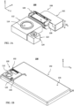
- FIG. 1A shows a multi-camera numbered 100 that comprises a folded STC numbered 102 according to some embodiments disclosed herein.
- STC 102 includes an aperture 104 and an object-side OPFE (O-OPFE) 106 and is included in a STC camera module 108.
- Multi-camera 100 further comprises a Wide camera 112 having a Wide aperture 114 and an Ultra-Wide camera 122 having an Ultra-Wide aperture 124.
- An image sensor (not shown) of STC 102 is located in a plane substantially parallel to the x-y-plane.
- An image sensor (not shown) of Wide camera 112 is located in a plane substantially parallel to the x-z-plane.
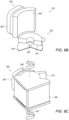
- FIG. 1B shows a mobile device (e.g. a smartphone) numbered 130 that includes multi-camera 100 in a perspective view.
- a rear surface 132 of mobile device 130 is visible.
- a front surface (not visible) may include a screen.
- Rear surface 132 is divided into two regions, a first regular region 134 where device 130 has a height H, and a second, "bump" region 136 where device 130 has a height H+H B (H B being the height of the bump).
- multi-camera 100 may be entirely included in bump region 136.
- FIG. 1B shows a mobile device (e.g. a smartphone) numbered 130 that includes multi-camera 100 in a perspective view.
- a rear surface 132 of mobile device 130 is visible.
- a front surface may include a screen.
- Rear surface 132 is divided into two regions, a first regular region 134 where device 130 has a height H, and a second, "bump" region 136 where device 130 has a height H+H
- a first region of multi-camera 100 having a first height H 1 may be included in bump region 136, whereas a second region of multi-camera 100 having a second height H 2 (H 2 ⁇ H 1 ) may be included in regular region 134.
- the latter is preferred from an industrial design point of view, as it allows minimizing the area size of bump region 136.
- Mobile device 130 may additionally include an application processor (AP - not shown).
- the AP may be configured to scan a scene with STC 102 's n-FOV T according to a user input.
- the AP may be configured to use image data from a Wide camera such as camera 112 to autonomously scan a scene with STC 102 's n-FOV T .
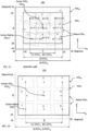
- FIG. 1C shows a known dual-camera field-of-view 140 that includes a FOVw from a Wide camera, a known STC s-FOV T , and 9 n-FOV TS from the known STC, marked 1-9.
- the center locations of FOVw and s-FOV T are identical.
- the 9 n-FOV TS represent the extreme scanning positions of the STC.
- n-FOV T 2 corresponds to the maximum scanning position along the positive y direction
- n-FOV T 3 corresponds to the maximum scanning position along both the positive y direction and the positive x direction, etc..
- Each n-FOV T has a n-FOV T center.
- the center n-FOV T 7 is indicated by "Center Native FOV T 7".
- a horizontal distance (LC-FOV T - RC-FOV T ", measured along x) between the n-FOV T center of a maximum left scanning position (“LC-FOV T ”) and the n-FOV T center of a maximum right scanning position (“RC-FOV T ") is also marked.
- FOVw is 64 degrees in a horizontal direction ("H-FOVw”, along the x-axis) and 48 degrees in a vertical direction ("V-FOVw", along the y-axis).
- FOV T is 46 degrees in the horizontal direction ("H-FOV T ") and 36 degrees in the vertical direction (“V-FOV T ”)
- LC-FOV T - RC-FOV T 27degrees. That is, FOV T ⁇ FOVw.
- FIG. 1D shows a dual-camera field-of-view 150 that includes a FOVw, a s-FOV T and 9 native n-FOV TS of a STC camera as disclosed herein.
- the center locations of FOVw and s-FOV T are identical.
- LC-FOV T - RC-FOV T 41 degrees.
- Significantly less pronounced POV aberrations and no Roll effects are visible in the n-FOV TS 1, 3, 4, 6, 7 and 9.
- s-FOV T may cover a 16:9 image ratio of FOVw, i.e. H-FOV T may be equal to or even larger than H-FOVw, but V-FOV T may be smaller than V-FOVw e.g. according to a ratio of 16:9.
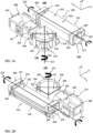
- FIG. 2A shows an embodiment of a folded STC numbered 200 disclosed herein in a perspective view.
- FIG. 2B shows folded STC 200 in another perspective view.
- STC 200 comprises an O-OPFE 202 (e.g. a prism or mirror) for folding a first optical path ("OP1") which is substantially parallel to the y-axis to a second OP ("OP2") which is substantially parallel to the x-axis, an image-side OPFE (“I-OPFE”) 204 (e.g. a prism or mirror, not visible in FIG. 2A ) for folding OP2 to a third optical path ("OP3”) which is substantially parallel to the z-axis.
- O-OPFE 202 e.g. a prism or mirror
- I-OPFE image-side OPFE
- STC 200 comprises a lens barrel 205 including a lens 206 (only partially visible here), an optional optical window 208 (e.g. an IR filter), and an image sensor 210.
- OP1, OP2 and OP3 are perpendicular to each other.
- O-OPFE 202 is carried by an O-OPFE holder 216 and I-OPFE 204 is carried by an I-OPFE holder 218.
- optically active areas of O-OPFE 202 are larger in size than the optically active areas of I-OPFE 204, a first side area 207 which (in zero scan position) is oriented parallel to the y-z-plane and a second side area 209 which is oriented parallel to the x-y-plane.
- the larger optical areas of O-OPFE 202 are required to provide light from all optical fields and for all scan positions of I-OPFE 204.
- an O-OPFE actuator 212 rotates O-OPFE 202 around a rotation axis 213 substantially parallel to OP3
- an I-OPFE actuator 214 rotates I-OPFE 204 around a rotation axis 215 substantially parallel to OP1.
- a barrel actuator 215 e.g. a voice coil motor - VCM
- a barrel actuator such as 215 may additionally move a lens barrel like 205 substantially parallel to OP1 and/or OP2 for OIS.
- STC 200 includes an O-OPFE drop prevention module 260 designed to prevent O-OPFE holder 212 from falling out of a camera module that includes STC 200 if a mobile device including the camera module is dropped.
- I-OPFE holder 218 includes an I-OPFE housing 219.
- I-OPFE housing 219 has a "C" shape, meaning that it surrounds I-OPFE 204 on three sides that are not optically active (top, bottom and back).
- EFL effective focal length
- O-OPFE actuator 212 includes an O-OPFE actuation module 220 and an O-OPFE sensing module 230. The two modules may be separate modules.
- O-OPFE sensing module 230 is located at both sides of O-OPFE holder 216.
- O-OPFE actuation module 220 includes a coil 222 (not visible here, but shown in FIG. 3B ), an actuation magnet 224 (not visible here, but shown in FIG. 3B ) and an actuation yoke 226.
- O-OPFE sensing module 230 includes a position sensor (e.g. a Hall sensor) 232 (see FIG. 5A ) and a sensing magnet 234 (see FIG. 5A ).
- An advantage of separating O-OPFE actuation module 220 and O-OPFE sensing module 230 is that position sensor 232 is decoupled from actuation coil 222.
- I-OPFE actuator 214 includes an I-OPFE actuation module 240 and an I-OPFE sensing module 250. The two modules may be separate modules.
- I-OPFE actuation module 240 includes an actuation coil 242 and an actuation magnet 244.
- I-OPFE sensing module 250 includes a position sensor (e.g. a Hall sensor) 252 (shown in FIG. 7A ) and a sensing magnet 254 (shown in FIG. 7A ).
- An advantage of separating I-OPFE actuation module 240 and I-OPFE sensing module 250 is that position sensor 252 is decoupled from actuation coil 242.
- the rotation axis 215 of I-OPFE 204 is at a relatively large distance from I-OPFE actuation module 240, so there is a large lever for rotating I-OPFE 204.
- the rotation axis 215 of I-OPFE 204 is at a relatively close distance from I-OPFE sensing module 240, so that the rotation of I-OPFE 204 can be sensed with a small stroke, i.e. over a small distance.
- FIG. 3A shows a cross-sectional view of an embodiment of a camera module numbered 310 that includes an STC disclosed herein and numbered 300.
- Camera module 310 is housed in (surrounded by) a camera module housing 321.
- STC 300 comprises an O-OPFE 302 (e.g. a prism) carried by an O-OPFE holder 316 for folding a first OP1 to a second OP2, an I-OPFE 304 (e.g. a prism) carried by an I-OPFE holder 318 for folding OP2 to a third OP3, a lens barrel (not shown) including a lens (not shown), an optional optical element (not shown), and an image sensor (not shown).
- O-OPFE 302 e.g. a prism
- I-OPFE 304 e.g. a prism
- I-OPFE holder 318 for folding OP2 to a third OP3
- a lens barrel not shown
- O-OPFE actuator 312 rotates O-OPFE 302 around axis 311 substantially parallel to OP3 and an I-OPFE actuator 314 (not visible here, see FIGS. 9A , 9B ) rotates I-OPFE 304 around axis 333 substantially parallel to OP1.
- a barrel actuator (not shown) linearly moves the lens barrel substantially parallel to OP3 for AF. In other examples, the barrel actuator may additionally linearly move the lens barrel substantially parallel to OP1 and/or OP2 for OIS.
- I-OPFE holder 318 includes an I-OPFE housing 319.
- O-OPFE actuator 312 includes an O-OPFE actuation module 320 and an O-OPFE sensing module 330 (see FIGS. 5E-F ).
- O-OPFE actuation module 320 includes an actuation coil 322, an actuation magnet 324 and an actuation yoke 326.
- O-OPFE sensing module 330 includes a position sensor 338 (e.g. a Hall sensor, see FIGS. 5E-F ) and a sensing magnet 334 (see FIGS. 5E-F ).
- An advantage of separating O-OPFE actuation module 320 and O-OPFE sensing module 330 is that the position sensor 338 is decoupled from actuation coil 322.
- I-OPFE actuator 314 includes an I-OPFE actuation module 340 (see FIGS. 9A-C ) and an I-OPFE sensing module 350 (see FIGS. 9A , 9B ).
- I-OPFE actuation module 340 includes a coil 902 and actuation magnet 904.
- I-OPFE sensing module 350 includes a position sensor 352 and a sensing magnet 914.
- FIG. 9A also shows a rotation axis 311 of O-OPFE 302 and a thickness H I-H of the upper and lower edges (surfaces) of I-OPFE holder 318. O-OPFE 302 is shown in a zero scan position.
- Camera module 310 has a non-uniform (or non-planar) top surface 313, so that camera module 310 is divided into two regions, an elevated region 315 where camera module 310 has a module height H M , and a "shoulder" region 317 where camera module 310 has a shoulder height Hs smaller than Hm.
- Camera module 310 has a uniform (or planar) bottom surface 319.
- O-OPFE 302 is located in elevated region 315.
- I-OPFE 304, lens barrel 305, optical element 307 and image sensor 308 are located in the shoulder region 317.
- An O-OPFE holder stopper 328 defines OPFE 302' s rotation range by limiting the rotational movement of O-OPFE holder 316.
- FIG. 3B shows in a cross-sectional view an embodiment of another camera module numbered 360 and which includes the STC shown in FIGS. 2A-2B .
- FIG. 3C shows camera module 360 in another cross-sectional view.
- Lens 206, rotation axis 213, a thickness H I-H of the upper and lower edges of I-OPFE holder 218, and an I-OPFE preload module 710 are visible in one or more of these figures.
- the height of lens 206 (“H A ") is marked.
- O-OPFE 202 is shown in a zero scan position.
- Camera module 360 is surrounded by a camera module housing 370.
- Camera module 360 has a non-uniform (or non-planar) top surface 363, so that camera module 360 is divided into two regions, an elevated region 365 where camera module 360 has a module height H M , and a shoulder region 367 where camera module 310 has a shoulder height Hs smaller than H M .
- Camera module 360 has a uniform (or planar) bottom surface 369.
- O-OPFE 202 is located in elevated region 365.
- I-OPFE 204, lens barrel 205, optical element 208 and image sensor 210 are located in the shoulder region 367.
- Rotation axes 311 and 213 in, respectively, camera modules 310 and 360 are located such that rotating respectively O-OPFEs 302 and 202 does not cause any height penalty in module height H M . This because rotating O-OPFEs 302 and 202 around rotation axes 311 and 213 respectively does not cause O-OPFE holders 316 and 216 to occupy y-values that are significantly smaller than the y-values that O-OPFE holders 316 and 216 occupy in the zero scan position.
- O-OPFE holder stopper 228 defines OPFE 202's rotation range.
- a relatively low f number (“f/#”) is desired for a compact camera, as a low f# increases the camera image's signal-to-noise ratio (SNR) and thus the camera's image quality.
- a low f/# is, amongst others, achieved by maximizing the aperture area ("AA”) of the camera lens.
- AA aperture area
- Hs height constraint which in turn is dictated by the height (or thickness) of a mobile device including the STC.
- H A height of the lens aperture, measured along the y-axis, see FIG. 3C
- W A width of the lens aperture, measured along the x-axis, i.e. perpendicular to the plane shown in FIG. 3C ).
- I-OPFE housing 219 may be made of metal. In an example, H I-H is about 0.15 mm. Housing 219 may be for example a metal frame that surrounds I-OPFE 204 in a "C"-shape both at its top, bottom and the one side that is not optically active. A small H I-H allows I-OPFE 204 to have a significantly larger height Hi-o than I-OPFE 304 for a same shoulder height Hs.
- Hi-o poses an upper limit for H A (see FIG. 3C ), i.e. Hi-o > H A . This because a Hi-o smaller than H A will cause vignetting, i.e. light that could still reach the lens would be blocked by I-OPFE 204, reducing the aperture of the optical system.
- H A , H M and Hs, as well as respective heights Ho-o (or H O-OPFE - measured along y) of O-OPFE 202 and Hi-o (or H I-OPFE ) of I-OPFE 204 are shown in FIGS. 3A-C .
- camera module 360 has following values:
- Hs may have values in the range 3-15mm
- H A may have values in the range 2-13mm
- H M may have values in the range 4-20mm
- Hi-o may have values in the range 2.5-15mm
- H O-O may have values in the range 2-20mm.
- a lens such as 206 may be "cut” (or "D-cut") as known in the art.
- a cut lens includes one or more lens elements L i that have a height H Li which is smaller than their width Wu.
- Wu may be greater than Hu by a percentage of about 5% - 100%.
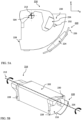
- FIG. 4 shows a segment of a mobile device 400 that includes camera module 310 in a cross-sectional view.
- a rear (back) surface 410 of mobile device 400 is divided into two regions, a first regular region 412 where device 400 has a regular height H, and a second, "bump" region 414 where device 400 has an elevated height H+H B .
- I-OPFE sensing module 350 and position sensor 352 are visible.
- elevated region 315 (having height H M ) is integrated in elevated bump region 414 of mobile device 400
- shoulder region 317 (having height Hs) is integrated in regular region 412 of mobile device 400.
- camera module 360 may be included in a mobile device such as mobile device 400 in the same way, i.e. its elevated region 365 may be integrated in an elevated bump region of the mobile device, and its shoulder region 367 may be integrated in a regular region of the mobile device.
- FIG. 5A shows O-OPFE holder 216, O-OPFE actuation module 220 and O-OPFE sensing module 230 in a side view. Rotation axis 213 and actuation yoke 226 are visible. The rotation is mediated by a pivot ball 504. An O-OPFE holder stopper 228 limits O-OPFE holder 216's movement range as shown in FIG. 6A .
- O-OPFE sensing module 230 is located next to OPFE 202 and the magnetic sensing occurs in a plane parallel to the x-y-plane.
- FIG. 5B shows O-OPFE holder 216 and O-OPFE actuation module 220 in a perspective view.
- Two O-OPFE holder stoppers 228, rotation axis 213 and actuation yoke 226 are visible.
- FIG. 5C shows O-OPFE holder 216 and O-OPFE actuation module 220 in another perspective view.
- O-OPFE actuation magnet 224 as well as some components shown in FIGS. 5A and 5B are visible here as well.
- FIG. 5D shows O-OPFE holder 316 in a perspective view.
- O-OPFE holder 316 includes two stray light masks 512 and 514 for stray light prevention.
- O-OPFE 302 and O-OPFE 202 may be prisms made of high refractive index ("n") material (e.g. n>1.7) for compact beam guiding, allowing a compact camera module with ⁇ 30% vignetting (light loss) even for maximal rotation angles and/or maximal optical fields.
- n refractive index
- FIG. 5E shows O-OPFE holder 316 in another perspective view.
- O-OPFE sensing module 330 including position sensor 338 and sensing magnet 334 are visible.
- FIG. 5F shows O-OPFE holder 316 in yet another perspective view.
- O-OPFE actuation module 320 and O-OPFE sensing module 330 are visible.
- the magnetic sensing occurs in a plane perpendicular to the x-y-plane.
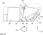
- FIG. 6A shows a segment of camera module 310 in a cross-sectional view.
- O-OPFE 302 is shown in a maximum right scan position.
- "Right" scan position here refers to the fact that the n-FOV T of STC 300 is oriented towards the right by rotating O-OPFE 302 around rotation axis 311 in a clockwise rotation direction 602.
- O-OPFE holder stopper 328 limits a further clockwise rotational movement of O-OPFE holder 316 by touching module housing 321. This prevents O-OPFE holder 316 and I-OPFE holder 318 (not shown) from touching each other and it defines (or limits) the maximum rotation (or "scanning") range of O-OPFE 302 in clockwise direction. Consequently, O-OPFE holder stopper 328 allows a compact camera design (for example in a smartphone camera) by allowing O-OPFE 316 and O-OPFE 318 to be located close to each other.
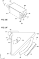
- FIG. 6B shows a segment of camera module 360 in a cross-sectional view.
- O-OPFE 202 is shown in a maximum right scan position. In this position, O-OPFE holder right stopper 612 limits a further clockwise rotational movement of O-OPFE holder 216 by touching module housing 370.
- FIG. 6C shows the segment of camera module 360 shown in FIG. 6B with O-OPFE 202 in a maximum left scan position.
- "Left" scan position here refers to the fact that the n-FOV T of STC 200 is oriented towards the left by rotating O-OPFE 202 around rotation axis 213 in a counter-clockwise rotation direction 604.
- O-OPFE holder left stopper 614 limits a further counter-clockwise rotational movement of O-OPFE holder 216 by touching module housing 370.
- the scanning range of O-OPFE 202 may be symmetric, i.e. a scanning range towards a left side (lower x-values) and right side (higher x-values) with respect to a zero scan position are identical.
- a maximum rotation range of O-OPFE 202 may be about ⁇ 11.5 degrees, wherein about ⁇ 10 degrees may be used for scanning the n-FOV T , and about ⁇ 1.5 degrees may be used for OIS.
- the scanning range may be used in a different ratio for FOV scanning and OIS, e.g. about ⁇ 10.5 degrees may be used for scanning the n-FOV T , and about ⁇ 1.0 degrees may be used for OIS.
- a maximum rotation range of O-OPFE 202 may be about ⁇ 5degrees - ⁇ 20 degrees.
- FIG. 7A shows I-OPFE holder 218 in a top view. Rotation axis 215 of I-OPFE holder 218 is shown. A pivot ball 704 is located in a pivot groove 706 (not visible here, but see FIG. 7B ) at rotation center axis 215 to mediate the rotational movement.
- I-OPFE preload module 710 includes an I-OPFE preload magnet 712 (not visible here, but in FIG. 7B ) and an I-OPFE preload yoke 714.
- I-OPFE holder 218 has independent modules for actuation (module 240), sensing (module 250) and preload (module 710).
- the rotation of I-OPFE 204 is mediated by two ball-groove mechanisms, a first one formed by ball 722 and groove 724, a second one formed by ball 726 and groove 728.
- I-OPFE holder 218 includes an I-OPFE drop prevention and rotation stop module 740.
- Module 740 includes a first groove 742 and a second groove 746.
- a first pin 744 (not visible here, but in FIGS. 8A-B ) is inserted in groove 742, and a second pin 748 (not visible here, but in FIGS. 8A-B ) is inserted in groove 746.
- FIG. 7B shows camera module 360 without housing module housing 370 in a cross-sectional view. Preload magnet 712 is visible.
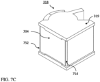
- FIG. 7C shows I-OPFE holder 318 in a perspective view.
- I-OPFE holder 318 is shown here including two stray light masks 752 and 754 for stray light prevention.
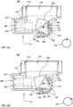
- FIG. 8A shows camera module 360 without top surface 363 in a maximum right scan position in a cross-sectional view.
- "Right" scan position here refers to the fact that an object-facing side 802 of I-OPFE 204 is oriented towards the right by rotating it around rotation axis 215 in a clockwise rotation direction 702.
- Camera module 360 includes two I-OPFE drop prevention modules 740 designed to prevent I-OPFE holder 218 to fall out of a camera module such as 310 or 360 in case that an including mobile device is dropped.
- Each of the I-OPFE drop prevention modules 740 includes a pin and groove assembly: pin 744 is inserted in groove 742, and pin 748 is inserted in groove 746.
- I-OPFE drop prevention and rotation stop module 740 is visible. It prevents I-OPFE holder 218 to fall out of a camera module such as 310 or 360 in case that a mobile device including it is dropped. Module 740 additionally limits the rotational movement of I-OPFE 204. In the maximum right scan position, pin 744 and pin 748 touch a top margin (the margin with the highest y-value) 804 and a right margin (the margin with the highest x-value) 806 of groove 742 and 746 respectively. This prevents I-OPFE 204 from further clockwise rotation.
- a lens barrel actuation ball guide module 808 includes two groove-rail modules 810 and 812 that mediate the movement of lens barrel 205.
- FIG. 8B shows camera module 360 without top surface 363 in a maximum left scan position in a cross-sectional view.
- Object-facing side 802 of I-OPFE 204 is oriented towards the left by rotating it around rotation axis 215 in a counter-clockwise rotation direction 704.
- pin 744 and pin 748 touch a bottom margin 814 (the margin with the lowest y-value) and a left margin 816 (the margin with the lowest x-value) of groove 742 and 746 respectively.
- the scanning range of I-OPFE 204 may be symmetric, i.e. a scanning range towards a left side (lower x-values) and right side (higher x-values) with respect to a zero scan position are identical.
- a maximum rotation range of I-OPFE 204 may be about ⁇ 14 degrees, wherein about ⁇ 12.5 degrees may be used for scanning the n-FOV T , and about ⁇ 1.5 degrees may be used for OIS.
- the scanning range may be used in a different ratio for FOV scanning and OIS.
- a maximum rotation range of I-OPFE 204 may be about ⁇ 5degrees - ⁇ 25 degrees.
- FIGS. 9A-C show I-OPFE 304 as well as I-OPFE actuator 314 which rotates I-OPFE 304 around rotation axis 333.
- I-OPFE actuator 314 includes I-OPFE actuation module 340 and I-OPFE sensing module 350.
- FIG. 9A shows I-OPFE 304 and I-OPFE actuator 314 in a bottom view.
- I-OPFE actuation module 340 includes an actuation coil 902 and an actuation magnet 904.
- I-OPFE sensing module 350 includes position sensor 352 and a sensing magnet 914.
- a pivot ball 922 is located at rotation axis 333. Pivot ball 922 and support balls 924 and 926 mediate the rotation of 1-OPFE 304.
- FIG. 9B shows I-OPFE actuator 314 without I-OPFE 304 in a perspective view.
- FIG. 9C shows I-OPFE 304 and I-OPFE actuation module 340 in a perspective view.
- Sensing yoke 916 which is included in I-OPFE sensing module 350 is visible.
- the axis of rotation 333 is marked.
- a sensing yoke 916 which is included in I-OPFE sensing module 350 is visible in both FIGS. 9B and 9C .
- Position sensor 352 is decoupled from the magnetic field of coil 902.
- Rotation axis 333 is at a relatively large distance from I-OPFE actuation module 340, providing a large lever for rotational actuation.
- Rotation axis 333 is at relatively short distance from position sensor 352, so that sensing of large rotational actuation I-OPFE 304 can be performed within a small stroke.
- the term “substantially” is used herein to imply the possibility of variations in values within an acceptable range. According to one example, the term “substantially” used herein should be interpreted to imply possible variation of up to 5% over or under any specified value. According to another example, the term “substantially” used herein should be interpreted to imply possible variation of up to 2.5% over or under any specified value. According to a further example, the term “substantially” used herein should be interpreted to imply possible variation of up to 1% over or under any specified value.
Landscapes
- Physics & Mathematics (AREA)
- General Physics & Mathematics (AREA)
- Optics & Photonics (AREA)
- Engineering & Computer Science (AREA)
- Multimedia (AREA)
- Signal Processing (AREA)
- Radar, Positioning & Navigation (AREA)
- Remote Sensing (AREA)
- Studio Devices (AREA)
- Lenses (AREA)
- Image Input (AREA)
Description
- This application claims the benefit of priority from
U.S. Provisional patent application No. 63/110,057 filed November 5, 2020 - The subject matter disclosed herein relates in general to compact mobile cameras and in particular to mobile scanning telephoto ("Tele") cameras.
- Mobile electronic handheld devices (or just "mobile devices" or "electronic devices") such as smartphones having two or more compact cameras (also referred to as "multi-cameras") are known. The two or more cameras have lenses with different focal lengths that capture images of a same scene with different fields of view (FOVs). For example, a multi-camera may include a Wide camera having a Wide camera FOV ("FOVw") of e.g. 80 degrees and a Tele (or "zoom") camera having a narrower FOV ("native FOVT" or ("n-FOVT") of e.g. 25 degrees and with higher spatial resolution (for example 3-5 times higher) than that of the Wide camera.
- Tele cameras with scanning capability ("scanning Tele cameras" or "STCs") for expanding the native fields-of-view n-FOVT to an effective Tele FOV (also referred to as "scanning FOVT" or "s-FOVT") overcome some of the limitations that relate to narrow n-FOVTS. Compact STCs can be realized in a folded camera such as described for example in co-owned
US patent 10578948 - STCs based on rotating a single OPFE along two directions for FOV scanning have drawbacks, such as e.g. a limited scanning range (since in general s-FOVT < FOVw), POV aberrations, and the rotation of the image on the image sensor (known as "Roll" effect). Solutions that correct for POV aberrations and the Roll effect are described in co-owned international patent application
PCT/IB2021/056311 - There is need and it would be beneficial to have a compact scanning Tele camera for incorporation in a mobile device that supports all of the following conditions:
- Large s-FOVT, e.g. s-FOVT= FOVw;
- FOVT scanning without causing POV aberrations and/or a Roll effect; and
- Use of lenses having large aperture areas, given the size constraints of modern mobile devices (particularly of smartphones). Document
EP3707893 discloses a digital camera including a lens having a lens optical axis, such that an image sensor is equipped with the lens. A first optical path folding element (OPFE) is provided for folding the light arriving from an object in a first optical path to a second optical path substantially aligned with the lens optical axis. A second OPFE is provided for folding the light from the second optical path to a third optical path toward the image sensor. - The present invention is defined by the appended claims.
- Non-limiting examples of embodiments disclosed herein are described below with reference to figures attached hereto that are listed following this paragraph. The drawings and descriptions are meant to illuminate and clarify embodiments disclosed herein, and should not be considered limiting in any way. Like elements in different drawings may be indicated by like numerals. Elements in the drawings are not necessarily drawn to scale.
-
FIG. 1A shows a multi-camera including a folded STC disclosed herein; -
FIG. 1B shows handheld device including that includes the multi-camera ofFIG. 1A in a perspective view; -
FIG. 1C shows a dual-camera FOV that includes a FOVw, a s-FOVT and 9 n-FOVTS from a known folded STC camera; -
FIG. 1D shows a dual-camera FOV that includes a FOVw, a s-FOVT and 9 n-FOVTS from a folded STC camera as disclosed herein; -
FIG. 2A shows an embodiment of a folded STC disclosed herein in a first perspective view; -
FIG. 2B shows the folded STC ofFIG. 2A in a second perspective view; -
FIG. 3A shows a segment of a handheld device that includes a folded STC as inFIG. 2A in a cross-sectional view; -
FIG. 3B shows in a cross-sectional view an embodiment of another camera module disclosed herein, which includes the folded STC shown inFIGS. 2A-2B ; -
FIG. 3C shows the camera module ofFIG. 3B in another cross-sectional view; -
FIG. 4 shows a camera module disclosed herein in a cross-sectional view; -
FIG. 5A shows an object-side OPFE (O-OPFE) and an O-OPFE actuation module in a side view; -
FIG. 5B shows an O-OPFE holder and the O-OPFE actuation module ofFIG. 5A in a perspective view; -
FIG. 5C shows the O-OPFE holder and the O-OPFE actuation module ofFIGS. 5A-5B in another perspective view; -
FIG. 5D shows another O-OPFE holder in a perspective view; -
FIG. 5E shows the O-OPFE holder ofFIG. 5D in another perspective view; -
FIG. 5F shows the O-OPFE holder ofFIG. 5D-5E in a side view; -
FIG. 6A shows a segment of the camera module ofFIG. 3A in a cross-sectional view; -
FIG. 6B shows a segment of camera module ofFIG. 3B in a cross-sectional view; -
FIG. 6C shows the segment of camera module ofFIG. 6B with an O-OPFE in a maximum left scan position; -
FIG. 7A shows an image side OPFE (I-OPFE) holder in the folded STC ofFIG. 2A in a top view; -
FIG. 7B shows the camera module ofFIG. 3B without a module housing in a cross-sectional view; -
FIG. 7C shows an I-OPFE holder in the folded STC ofFIG. 3A in a perspective view; -
FIG. 8A shows the camera module ofFIG. 3B without the module housing in a maximum right scan position in a cross-sectional view; -
FIG. 8B shows the camera module ofFIG. 3B without the module housing in a maximum left scan position in a cross-sectional view. -
FIG. 9A shows the I-OPFE and I-OPFE actuator ofFIG. 7C in a bottom view; -
FIG. 9B shows the I-OPFE actuator without the I-OPFE in a perspective view; -
FIG. 9C shows the I-OPFE and the I-OPFE actuation module in a perspective view. -
FIG. 1A shows a multi-camera numbered 100 that comprises a folded STC numbered 102 according to some embodiments disclosed herein.STC 102 includes anaperture 104 and an object-side OPFE (O-OPFE) 106 and is included in aSTC camera module 108. Multi-camera 100 further comprises aWide camera 112 having aWide aperture 114 and anUltra-Wide camera 122 having anUltra-Wide aperture 124. An image sensor (not shown) ofSTC 102 is located in a plane substantially parallel to the x-y-plane. An image sensor (not shown) ofWide camera 112 is located in a plane substantially parallel to the x-z-plane. -
FIG. 1B shows a mobile device (e.g. a smartphone) numbered 130 that includes multi-camera 100 in a perspective view. Arear surface 132 ofmobile device 130 is visible. A front surface (not visible) may include a screen.Rear surface 132 is divided into two regions, a firstregular region 134 wheredevice 130 has a height H, and a second, "bump"region 136 wheredevice 130 has a height H+HB (HB being the height of the bump). In some embodiments, multi-camera 100 may be entirely included inbump region 136. In other embodiments and as for example shown inFIG. 4 , a first region of multi-camera 100 having a first height H1 may be included inbump region 136, whereas a second region of multi-camera 100 having a second height H2 (H2 < H1) may be included inregular region 134. The latter is preferred from an industrial design point of view, as it allows minimizing the area size ofbump region 136.Mobile device 130 may additionally include an application processor (AP - not shown). In some examples, the AP may be configured to scan a scene withSTC 102's n-FOVT according to a user input. In other examples, the AP may be configured to use image data from a Wide camera such ascamera 112 to autonomously scan a scene withSTC 102's n-FOVT. -
FIG. 1C shows a known dual-camera field-of-view 140 that includes a FOVw from a Wide camera, a known STC s-FOVT, and 9 n-FOVTS from the known STC, marked 1-9. The center locations of FOVw and s-FOVT are identical. The 9 n-FOVTS represent the extreme scanning positions of the STC. For example, n-FOV T2 corresponds to the maximum scanning position along the positive y direction, n-FOV T3 corresponds to the maximum scanning position along both the positive y direction and the positive x direction, etc.. Each n-FOVT has a n-FOVT center. For example, the center n-FOV T 7 is indicated by "CenterNative FOV T 7". A horizontal distance ("LC-FOVT - RC-FOVT", measured along x) between the n-FOVT center of a maximum left scanning position ("LC-FOVT") and the n-FOVT center of a maximum right scanning position ("RC-FOVT") is also marked. - In the example related to
FIG. 1C , FOVw is 64 degrees in a horizontal direction ("H-FOVw", along the x-axis) and 48 degrees in a vertical direction ("V-FOVw", along the y-axis). FOVT is 46 degrees in the horizontal direction ("H-FOVT") and 36 degrees in the vertical direction ("V-FOVT") Here, LC-FOVT - RC-FOVT = 27degrees. That is, FOVT < FOVw. In this example, H-FOVT ≈ 0.7 x H-FOVw. This means that the STC cannot capture objects located at the edges of FOVw. POV aberrations and a Roll effect are visible in n-FOV -
FIG. 1D shows a dual-camera field-of-view 150 that includes a FOVw, a s-FOVT and 9 native n-FOVTS of a STC camera as disclosed herein. The center locations of FOVw and s-FOVT are identical. As inFIG. 1C , FOVw is H-FOVw= 64 degrees and V-FOVw= 48 degrees. Here, LC-FOVT - RC-FOVT = 41 degrees. InFIG. 1D , s-FOVT ≈ FOVw, H-FOVw ≈ H-FOVT and V-FOVW ≈ V-FOVT. This means that the STC can capture all objects located in FOVw. Significantly less pronounced POV aberrations and no Roll effects are visible in the n-FOV - In other embodiments, s-FOVT may cover a 16:9 image ratio of FOVw, i.e. H-FOVT may be equal to or even larger than H-FOVw, but V-FOVT may be smaller than V-FOVw e.g. according to a ratio of 16:9.
-
FIG. 2A shows an embodiment of a folded STC numbered 200 disclosed herein in a perspective view.FIG. 2B shows foldedSTC 200 in another perspective view. With reference to the coordinate system ofFIG. 2A ,STC 200 comprises an O-OPFE 202 (e.g. a prism or mirror) for folding a first optical path ("OP1") which is substantially parallel to the y-axis to a second OP ("OP2") which is substantially parallel to the x-axis, an image-side OPFE ("I-OPFE") 204 (e.g. a prism or mirror, not visible inFIG. 2A ) for folding OP2 to a third optical path ("OP3") which is substantially parallel to the z-axis. In addition,STC 200 comprises alens barrel 205 including a lens 206 (only partially visible here), an optional optical window 208 (e.g. an IR filter), and animage sensor 210. OP1, OP2 and OP3 are perpendicular to each other. O-OPFE 202 is carried by an O-OPFE holder 216 and I-OPFE 204 is carried by an I-OPFE holder 218. - It is visible that the optically active areas of O-
OPFE 202, atop area 201 which (in zero scan position) is oriented parallel to the x-z-plane and aside area 203 which is oriented parallel to the y-z-plane, are larger in size than the optically active areas of I-OPFE 204, afirst side area 207 which (in zero scan position) is oriented parallel to the y-z-plane and asecond side area 209 which is oriented parallel to the x-y-plane. The larger optical areas of O-OPFE 202 are required to provide light from all optical fields and for all scan positions of I-OPFE 204. - In use, for scanning a scene with n-FOVT and/or optical image stabilization (OIS), an O-
OPFE actuator 212 rotates O-OPFE 202 around arotation axis 213 substantially parallel to OP3, and an I-OPFE actuator 214 rotates I-OPFE 204 around arotation axis 215 substantially parallel to OP1. A barrel actuator 215 (e.g. a voice coil motor - VCM) moveslens barrel 205 substantially parallel to OP3 for autofocusing (AF). In other examples, a barrel actuator such as 215 may additionally move a lens barrel like 205 substantially parallel to OP1 and/or OP2 for OIS.STC 200 includes an O-OPFEdrop prevention module 260 designed to prevent O-OPFE holder 212 from falling out of a camera module that includesSTC 200 if a mobile device including the camera module is dropped. I-OPFE holder 218 includes an I-OPFE housing 219. In some camera module embodiments (such as in anembodiment 360 below), I-OPFE housing 219 has a "C" shape, meaning that it surrounds I-OPFE 204 on three sides that are not optically active (top, bottom and back). -
STC 200 may have an effective focal length (EFL) in the range of EFL= 5-50 mm. - O-
OPFE actuator 212 includes an O-OPFE actuation module 220 and an O-OPFE sensing module 230. The two modules may be separate modules. O-OPFE sensing module 230 is located at both sides of O-OPFE holder 216. O-OPFE actuation module 220 includes a coil 222 (not visible here, but shown inFIG. 3B ), an actuation magnet 224 (not visible here, but shown inFIG. 3B ) and anactuation yoke 226. O-OPFE sensing module 230 includes a position sensor (e.g. a Hall sensor) 232 (seeFIG. 5A ) and a sensing magnet 234 (seeFIG. 5A ). An advantage of separating O-OPFE actuation module 220 and O-OPFE sensing module 230 is thatposition sensor 232 is decoupled fromactuation coil 222. - I-
OPFE actuator 214 includes an I-OPFE actuation module 240 and an I-OPFE sensing module 250. The two modules may be separate modules. I-OPFE actuation module 240 includes anactuation coil 242 and anactuation magnet 244. I-OPFE sensing module 250 includes a position sensor (e.g. a Hall sensor) 252 (shown inFIG. 7A ) and a sensing magnet 254 (shown inFIG. 7A ). An advantage of separating I-OPFE actuation module 240 and I-OPFE sensing module 250 is thatposition sensor 252 is decoupled fromactuation coil 242. Therotation axis 215 of I-OPFE 204 is at a relatively large distance from I-OPFE actuation module 240, so there is a large lever for rotating I-OPFE 204. Therotation axis 215 of I-OPFE 204 is at a relatively close distance from I-OPFE sensing module 240, so that the rotation of I-OPFE 204 can be sensed with a small stroke, i.e. over a small distance. -
FIG. 3A shows a cross-sectional view of an embodiment of a camera module numbered 310 that includes an STC disclosed herein and numbered 300.Camera module 310 is housed in (surrounded by) acamera module housing 321.STC 300 comprises an O-OPFE 302 (e.g. a prism) carried by an O-OPFE holder 316 for folding a first OP1 to a second OP2, an I-OPFE 304 (e.g. a prism) carried by an I-OPFE holder 318 for folding OP2 to a third OP3, a lens barrel (not shown) including a lens (not shown), an optional optical element (not shown), and an image sensor (not shown). OP1 and OP2 and OP3 are not shown, but are perpendicular to each other and are oriented along identical axes as shown forSTC 200. - O-
OPFE actuator 312 rotates O-OPFE 302 aroundaxis 311 substantially parallel to OP3 and an I-OPFE actuator 314 (not visible here, seeFIGS. 9A ,9B ) rotates I-OPFE 304 aroundaxis 333 substantially parallel to OP1. A barrel actuator (not shown) linearly moves the lens barrel substantially parallel to OP3 for AF. In other examples, the barrel actuator may additionally linearly move the lens barrel substantially parallel to OP1 and/or OP2 for OIS. I-OPFE holder 318 includes an I-OPFE housing 319.STC 300 may have an effective focal length (EFL) in the range of EFL= 5-50 mm. - O-
OPFE actuator 312 includes an O-OPFE actuation module 320 and an O-OPFE sensing module 330 (seeFIGS. 5E-F ). O-OPFE actuation module 320 includes anactuation coil 322, anactuation magnet 324 and anactuation yoke 326. O-OPFE sensing module 330 includes a position sensor 338 (e.g. a Hall sensor, seeFIGS. 5E-F ) and a sensing magnet 334 (seeFIGS. 5E-F ). An advantage of separating O-OPFE actuation module 320 and O-OPFE sensing module 330 is that theposition sensor 338 is decoupled fromactuation coil 322. - I-
OPFE actuator 314 includes an I-OPFE actuation module 340 (seeFIGS. 9A-C ) and an I-OPFE sensing module 350 (seeFIGS. 9A ,9B ). I-OPFE actuation module 340 includes acoil 902 andactuation magnet 904. I-OPFE sensing module 350 includes aposition sensor 352 and asensing magnet 914. An advantage of separating I-OPFE actuation module 340 and I-OPFE sensing module 350 is thatposition sensor 352 is decoupled fromactuation coil 902. As visible inFIG. 9A ,rotation axis 333 of I-OPFE 304 is far from I-OPFE actuation module 340, so there is a large lever for rotating I-OPFE 304. As shown inFIG. 9A ,rotation axis 333 is relatively close to I-OPFE sensing module 340, so that the rotation of I-OPFE 304 can be sensed with a small stroke.FIG. 3A also shows arotation axis 311 of O-OPFE 302 and a thickness HI-H of the upper and lower edges (surfaces) of I-OPFE holder 318. O-OPFE 302 is shown in a zero scan position. -
Camera module 310 has a non-uniform (or non-planar)top surface 313, so thatcamera module 310 is divided into two regions, anelevated region 315 wherecamera module 310 has a module height HM, and a "shoulder"region 317 wherecamera module 310 has a shoulder height Hs smaller than Hm.Camera module 310 has a uniform (or planar)bottom surface 319. O-OPFE 302 is located inelevated region 315. I-OPFE 304, lens barrel 305, optical element 307 and image sensor 308 are located in theshoulder region 317. - An O-
OPFE holder stopper 328 definesOPFE 302's rotation range by limiting the rotational movement of O-OPFE holder 316. -
FIG. 3B shows in a cross-sectional view an embodiment of another camera module numbered 360 and which includes the STC shown inFIGS. 2A-2B .FIG. 3C showscamera module 360 in another cross-sectional view.Lens 206,rotation axis 213, a thickness HI-H of the upper and lower edges of I-OPFE holder 218, and an I-OPFE preload module 710 are visible in one or more of these figures. The height of lens 206 ("HA") is marked. - O-
OPFE 202 is shown in a zero scan position.Camera module 360 is surrounded by acamera module housing 370.Camera module 360 has a non-uniform (or non-planar)top surface 363, so thatcamera module 360 is divided into two regions, anelevated region 365 wherecamera module 360 has a module height HM, and ashoulder region 367 wherecamera module 310 has a shoulder height Hs smaller than HM. Camera module 360 has a uniform (or planar)bottom surface 369. O-OPFE 202 is located inelevated region 365. I-OPFE 204,lens barrel 205,optical element 208 andimage sensor 210 are located in theshoulder region 367. - Rotation axes 311 and 213 in, respectively,
camera modules OPFEs OPFEs rotation axes OPFE holders OPFE holders - O-
OPFE holder stopper 228 definesOPFE 202's rotation range. - As known, a relatively low f number ("f/#") is desired for a compact camera, as a low f# increases the camera image's signal-to-noise ratio (SNR) and thus the camera's image quality. A low f/# is, amongst others, achieved by maximizing the aperture area ("AA") of the camera lens. For obtaining a STC having low f/#, AA is to be maximized, given a certain Hs height constraint, which in turn is dictated by the height (or thickness) of a mobile device including the STC. For maximizing AA, one may maximize both HA (height of the lens aperture, measured along the y-axis, see
FIG. 3C ) and WA (width of the lens aperture, measured along the x-axis, i.e. perpendicular to the plane shown inFIG. 3C ). - For maximizing HA, a height difference ("penalty" or "P") between the HA and Hs needs to be minimized. For minimizing P, Hi-o needs to be maximized, as explained next. For minimizing HI-H (which maximizes Hi-o for a given Hs), I-
OPFE housing 219 may be made of metal. In an example, HI-H is about 0.15 mm.Housing 219 may be for example a metal frame that surrounds I-OPFE 204 in a "C"-shape both at its top, bottom and the one side that is not optically active. A small HI-H allows I-OPFE 204 to have a significantly larger height Hi-o than I-OPFE 304 for a same shoulder height Hs. Hi-o poses an upper limit for HA (seeFIG. 3C ), i.e. Hi-o > HA. This because a Hi-o smaller than HA will cause vignetting, i.e. light that could still reach the lens would be blocked by I-OPFE 204, reducing the aperture of the optical system. - HA, HM and Hs, as well as respective heights Ho-o (or HO-OPFE - measured along y) of O-
OPFE 202 and Hi-o (or HI-OPFE) of I-OPFE 204 are shown inFIGS. 3A-C . - In an example,
camera module 360 has following values: - HS = 5.8mm
- HA = 4.4mm
- P = 1.4mm
- HM= 7.3mm
- HO-O = 5.5mm
- HI-O = 4.8mm
- In other examples, Hs may have values in the range 3-15mm, HA may have values in the range 2-13mm, HM may have values in the range 4-20mm, Hi-o may have values in the range 2.5-15mm and HO-O may have values in the range 2-20mm.
- For maximizing WA, a lens such as 206 may be "cut" (or "D-cut") as known in the art. A cut lens includes one or more lens elements Li that have a height HLi which is smaller than their width Wu. In some examples, Wu may be greater than Hu by a percentage of about 5% - 100%. With respect to the example in
camera module 360, WA of acut lens 206 having a height of HA = 4.4mm may be in the range WA= 4.4mm - 10mm. -
FIG. 4 shows a segment of amobile device 400 that includescamera module 310 in a cross-sectional view. A rear (back)surface 410 ofmobile device 400 is divided into two regions, a firstregular region 412 wheredevice 400 has a regular height H, and a second, "bump"region 414 wheredevice 400 has an elevated height H+HB. I-OPFE sensing module 350 andposition sensor 352 are visible. - To compactly integrate
camera module 310 intomobile device 400, elevated region 315 (having height HM) is integrated inelevated bump region 414 ofmobile device 400, and shoulder region 317 (having height Hs) is integrated inregular region 412 ofmobile device 400. In other embodiments,camera module 360 may be included in a mobile device such asmobile device 400 in the same way, i.e. itselevated region 365 may be integrated in an elevated bump region of the mobile device, and itsshoulder region 367 may be integrated in a regular region of the mobile device. -
FIG. 5A shows O-OPFE holder 216, O-OPFE actuation module 220 and O-OPFE sensing module 230 in a side view.Rotation axis 213 andactuation yoke 226 are visible. The rotation is mediated by apivot ball 504. An O-OPFE holder stopper 228 limits O-OPFE holder 216's movement range as shown inFIG. 6A . O-OPFE sensing module 230 is located next to OPFE 202 and the magnetic sensing occurs in a plane parallel to the x-y-plane. -
FIG. 5B shows O-OPFE holder 216 and O-OPFE actuation module 220 in a perspective view. Two O-OPFE holder stoppers 228,rotation axis 213 andactuation yoke 226 are visible. -
FIG. 5C shows O-OPFE holder 216 and O-OPFE actuation module 220 in another perspective view. O-OPFE actuation magnet 224 as well as some components shown inFIGS. 5A and 5B are visible here as well. -
FIG. 5D shows O-OPFE holder 316 in a perspective view. O-OPFE holder 316 includes two straylight masks OPFE 302 and O-OPFE 202 may be prisms made of high refractive index ("n") material (e.g. n>1.7) for compact beam guiding, allowing a compact camera module with < 30% vignetting (light loss) even for maximal rotation angles and/or maximal optical fields. -
FIG. 5E shows O-OPFE holder 316 in another perspective view. O-OPFE sensing module 330 includingposition sensor 338 andsensing magnet 334 are visible. -
FIG. 5F shows O-OPFE holder 316 in yet another perspective view. O-OPFE actuation module 320 and O-OPFE sensing module 330 are visible. The magnetic sensing occurs in a plane perpendicular to the x-y-plane. -
FIG. 6A shows a segment ofcamera module 310 in a cross-sectional view. O-OPFE 302 is shown in a maximum right scan position. "Right" scan position here refers to the fact that the n-FOVT ofSTC 300 is oriented towards the right by rotating O-OPFE 302 aroundrotation axis 311 in aclockwise rotation direction 602. In this position, O-OPFE holder stopper 328 limits a further clockwise rotational movement of O-OPFE holder 316 by touchingmodule housing 321. This prevents O-OPFE holder 316 and I-OPFE holder 318 (not shown) from touching each other and it defines (or limits) the maximum rotation (or "scanning") range of O-OPFE 302 in clockwise direction. Consequently, O-OPFE holder stopper 328 allows a compact camera design (for example in a smartphone camera) by allowing O-OPFE 316 and O-OPFE 318 to be located close to each other. -
FIG. 6B shows a segment ofcamera module 360 in a cross-sectional view. O-OPFE 202 is shown in a maximum right scan position. In this position, O-OPFE holderright stopper 612 limits a further clockwise rotational movement of O-OPFE holder 216 by touchingmodule housing 370. -
FIG. 6C shows the segment ofcamera module 360 shown inFIG. 6B with O-OPFE 202 in a maximum left scan position. "Left" scan position here refers to the fact that the n-FOVT ofSTC 200 is oriented towards the left by rotating O-OPFE 202 aroundrotation axis 213 in acounter-clockwise rotation direction 604. O-OPFE holder leftstopper 614 limits a further counter-clockwise rotational movement of O-OPFE holder 216 by touchingmodule housing 370. - As shown in
FIGS. 6B-C , the scanning range of O-OPFE 202 may be symmetric, i.e. a scanning range towards a left side (lower x-values) and right side (higher x-values) with respect to a zero scan position are identical. A maximum rotation range of O-OPFE 202 may be about ±11.5 degrees, wherein about ±10 degrees may be used for scanning the n-FOVT, and about ±1.5 degrees may be used for OIS. In other examples, the scanning range may be used in a different ratio for FOV scanning and OIS, e.g. about ±10.5 degrees may be used for scanning the n-FOVT, and about ±1.0 degrees may be used for OIS. In other examples, a maximum rotation range of O-OPFE 202 may be about ±5degrees - ±20 degrees. -
FIG. 7A shows I-OPFE holder 218 in a top view.Rotation axis 215 of I-OPFE holder 218 is shown. Apivot ball 704 is located in a pivot groove 706 (not visible here, but seeFIG. 7B ) atrotation center axis 215 to mediate the rotational movement. I-OPFE preload module 710 includes an I-OPFE preload magnet 712 (not visible here, but inFIG. 7B ) and an I-OPFE preload yoke 714. I-OPFE holder 218 has independent modules for actuation (module 240), sensing (module 250) and preload (module 710). The rotation of I-OPFE 204 is mediated by two ball-groove mechanisms, a first one formed byball 722 andgroove 724, a second one formed byball 726 andgroove 728. - I-
OPFE holder 218 includes an I-OPFE drop prevention androtation stop module 740.Module 740 includes afirst groove 742 and asecond groove 746. A first pin 744 (not visible here, but inFIGS. 8A-B ) is inserted ingroove 742, and a second pin 748 (not visible here, but inFIGS. 8A-B ) is inserted ingroove 746. -
FIG. 7B showscamera module 360 withouthousing module housing 370 in a cross-sectional view.Preload magnet 712 is visible. -
FIG. 7C shows I-OPFE holder 318 in a perspective view. I-OPFE holder 318 is shown here including two straylight masks -
FIG. 8A showscamera module 360 withouttop surface 363 in a maximum right scan position in a cross-sectional view. "Right" scan position here refers to the fact that an object-facingside 802 of I-OPFE 204 is oriented towards the right by rotating it aroundrotation axis 215 in aclockwise rotation direction 702.Camera module 360 includes two I-OPFEdrop prevention modules 740 designed to prevent I-OPFE holder 218 to fall out of a camera module such as 310 or 360 in case that an including mobile device is dropped. Each of the I-OPFEdrop prevention modules 740 includes a pin and groove assembly: pin 744 is inserted ingroove 742, and pin 748 is inserted ingroove 746. - I-OPFE drop prevention and
rotation stop module 740 is visible. It prevents I-OPFE holder 218 to fall out of a camera module such as 310 or 360 in case that a mobile device including it is dropped.Module 740 additionally limits the rotational movement of I-OPFE 204. In the maximum right scan position, pin 744 and pin 748 touch a top margin (the margin with the highest y-value) 804 and a right margin (the margin with the highest x-value) 806 ofgroove OPFE 204 from further clockwise rotation. - A lens barrel actuation
ball guide module 808 includes two groove-rail modules lens barrel 205. -
FIG. 8B showscamera module 360 withouttop surface 363 in a maximum left scan position in a cross-sectional view. Object-facingside 802 of I-OPFE 204 is oriented towards the left by rotating it aroundrotation axis 215 in acounter-clockwise rotation direction 704. In maximum left scan position, pin 744 and pin 748 touch a bottom margin 814 (the margin with the lowest y-value) and a left margin 816 (the margin with the lowest x-value) ofgroove - As seen in
FIGS. 8A-B , the scanning range of I-OPFE 204 may be symmetric, i.e. a scanning range towards a left side (lower x-values) and right side (higher x-values) with respect to a zero scan position are identical. A maximum rotation range of I-OPFE 204 may be about ±14 degrees, wherein about ±12.5 degrees may be used for scanning the n-FOVT, and about ±1.5 degrees may be used for OIS. In other examples, the scanning range may be used in a different ratio for FOV scanning and OIS. In other examples, a maximum rotation range of I-OPFE 204 may be about ±5degrees - ±25 degrees. -
FIGS. 9A-C show I-OPFE 304 as well as I-OPFE actuator 314 which rotates I-OPFE 304 aroundrotation axis 333. I-OPFE actuator 314 includes I-OPFE actuation module 340 and I-OPFE sensing module 350. -
FIG. 9A shows I-OPFE 304 and I-OPFE actuator 314 in a bottom view. I-OPFE actuation module 340 includes anactuation coil 902 and anactuation magnet 904. I-OPFE sensing module 350 includesposition sensor 352 and asensing magnet 914. Apivot ball 922 is located atrotation axis 333.Pivot ball 922 andsupport balls OPFE 304. -
FIG. 9B shows I-OPFE actuator 314 without I-OPFE 304 in a perspective view.FIG. 9C shows I-OPFE 304 and I-OPFE actuation module 340 in a perspective view.Sensing yoke 916 which is included in I-OPFE sensing module 350 is visible. The axis ofrotation 333 is marked. Asensing yoke 916 which is included in I-OPFE sensing module 350 is visible in bothFIGS. 9B and 9C . - The use of two separate magnets (904 and 914) provides separation of sensing and actuation.
Position sensor 352 is decoupled from the magnetic field ofcoil 902.Rotation axis 333 is at a relatively large distance from I-OPFE actuation module 340, providing a large lever for rotational actuation.Rotation axis 333 is at relatively short distance fromposition sensor 352, so that sensing of large rotational actuation I-OPFE 304 can be performed within a small stroke. - The disclosure is to be understood as not limited by the specific embodiments described herein, but only by the scope of the appended claims.
- Furthermore, for the sake of clarity the term "substantially" is used herein to imply the possibility of variations in values within an acceptable range. According to one example, the term "substantially" used herein should be interpreted to imply possible variation of up to 5% over or under any specified value. According to another example, the term "substantially" used herein should be interpreted to imply possible variation of up to 2.5% over or under any specified value. According to a further example, the term "substantially" used herein should be interpreted to imply possible variation of up to 1% over or under any specified value.
Claims (15)
- A camera module (100) comprising a scanning Tele camera (STC) (102), the STC (102, 200, 300) comprising:an object side optical path folding element O-OPFE (202, 302) for folding a first optical path OP1 to a second optical path OP2;an image side optical path folding element I-OPFE (204, 304) for folding OP2 to a third optical path OP3;an I-OPFEactuator (214, 314);a lens (206);a lens actuator; andan image sensor (210);characterized by further comprising:an O-OPFE actuator (212, 312);wherein STC (102, 200, 300) has a STC native field-of-view n-FOVT, wherein the O-OPFE actuator (212, 312) is configured to rotate the O-OPFE (202, 302) around a first axis and the I-OPFE actuator (214, 314) is configured to rotate the I-OPFE (204, 304) around a second axis for scanning a scene with the n-FOVT, wherein the lens actuator is configured to move the lens for focusing along a third axis, andwherein the first axis is perpendicular to the second axis and parallel to the third axis, and wherein the camera module (310) is divided into a first region having a module region height HM and a second region having a shoulder region height HS < HM, the lens having a maximum aperture height HA, all heights being measured along OP1, wherein HS < HA + 3mm.
- The camera module of claim 1, wherein HS < HA + 2mm.
- The camera module (100) of claim 1, wherein the I-OPFE (204, 304) has a height HI-OPFE measured along OP1, wherein HI-OPFE < HA + 2mm.
- The camera module (100) of claim 2 1, wherein the O-OPFE (202, 302) has a height HO-OPFE measured along OP1, wherein HM < HO-OPFE + 3mm.
- The camera module (100) of claim 1, wherein the scanning provides an effective Tele scanning FOV s-FOVT, and wherein a horizontal dimension H-FOVT of s-FOVT is greater than 50 degrees.
- The camera module (100) of claim 1, wherein H-FOVT > 60 degrees.
- The camera module (100) of claim 1, wherein the lens is positioned between the I-OPFE (204, 304) and the image sensor (210).
- The camera module (100) of claim 1, wherein OP1, OP2 and OP3 are perpendicular to each other.
- The camera module (100) of claim 1, wherein the rotation of the O-OPFE (202, 302) is around a first axis parallel to OP3 for scanning the n-FOVT in a first scan direction, and wherein the rotation of the I-OPFE (204, 304) is around a second axis parallel to OP1 for scanning the n-FOVT in a second scan direction.
- The camera module (100) of claim 1, wherein the rotation of the O-OPFE (202, 302) and of the I-OPFE (204, 304) is by more than ±7.5 degrees around a zero scan position.
- The camera module (100) of claim 1, the rotation of the O-OPFE (202, 302) and of the I-OPFE (204, 304) is by more than ±10 degrees around a zero scan position.
- The camera module (100) of claim 1, wherein the O-OPFE (202, 302) is a prism made of a material having a refractive index n >1.7.
- The camera module (100) of claim 1, wherein the O-OPFE (202, 302) and the I-OPFE (204, 304) are included in respective O-OPFE (212, 216, 316) and I-OPFE holders (218, 318), and wherein both the O-OPFE holder (212, 216, 316) and the I-OPFE holder (218, 318) include a stray light mask (752, 754).
- The camera module (100) of claim 13, wherein the I-OPFE holder(218, 318) is included in a housing (319, 321, 370) made of metal.
- The camera module (100) of claim 13, wherein the I-OPFE holder (218, 318) is included in a housing with a height HI-H measured along OP1, wherein HI-H <0.5mm.
Priority Applications (1)
| Application Number | Priority Date | Filing Date | Title |
|---|---|---|---|
| EP24199717.0A EP4471486A3 (en) | 2020-11-05 | 2021-11-05 | Scanning tele camera based on two optical path folding element field-of-view scanning |
Applications Claiming Priority (2)
| Application Number | Priority Date | Filing Date | Title |
|---|---|---|---|
| US202063110057P | 2020-11-05 | 2020-11-05 | |
| PCT/IB2021/060244 WO2022097071A1 (en) | 2020-11-05 | 2021-11-05 | Scanning tele camera based on two optical path folding element field-of-view scanning |
Related Child Applications (1)
| Application Number | Title | Priority Date | Filing Date |
|---|---|---|---|
| EP24199717.0A Division EP4471486A3 (en) | 2020-11-05 | 2021-11-05 | Scanning tele camera based on two optical path folding element field-of-view scanning |
Publications (4)
| Publication Number | Publication Date |
|---|---|
| EP4085285A1 EP4085285A1 (en) | 2022-11-09 |
| EP4085285A4 EP4085285A4 (en) | 2023-06-28 |
| EP4085285C0 EP4085285C0 (en) | 2024-10-09 |
| EP4085285B1 true EP4085285B1 (en) | 2024-10-09 |
Family
ID=81456997
Family Applications (2)
| Application Number | Title | Priority Date | Filing Date |
|---|---|---|---|
| EP24199717.0A Pending EP4471486A3 (en) | 2020-11-05 | 2021-11-05 | Scanning tele camera based on two optical path folding element field-of-view scanning |
| EP21888800.6A Active EP4085285B1 (en) | 2020-11-05 | 2021-11-05 | Scanning tele camera based on two optical path folding element field-of-view scanning |
Family Applications Before (1)
| Application Number | Title | Priority Date | Filing Date |
|---|---|---|---|
| EP24199717.0A Pending EP4471486A3 (en) | 2020-11-05 | 2021-11-05 | Scanning tele camera based on two optical path folding element field-of-view scanning |
Country Status (5)
| Country | Link |
|---|---|
| US (3) | US12271105B2 (en) |
| EP (2) | EP4471486A3 (en) |
| KR (5) | KR102592576B1 (en) |
| CN (4) | CN116381907A (en) |
| WO (1) | WO2022097071A1 (en) |
Families Citing this family (4)
| Publication number | Priority date | Publication date | Assignee | Title |
|---|---|---|---|---|
| WO2022097071A1 (en) * | 2020-11-05 | 2022-05-12 | Corephotonics Ltd. | Scanning tele camera based on two optical path folding element field-of-view scanning |
| KR102696960B1 (en) * | 2020-12-26 | 2024-08-19 | 코어포토닉스 리미티드 | Video support in a multi-aperture mobile camera with a scanning zoom camera |
| TW202429156A (en) * | 2022-12-11 | 2024-07-16 | 以色列商核心光電有限公司 | Refractive and hybrid lenses for compact folded tele cameras |
| CN120161661A (en) * | 2023-02-15 | 2025-06-17 | 核心光电有限公司 | Wide-angle compact optical image stabilization for foldable cameras |
Family Cites Families (304)
| Publication number | Priority date | Publication date | Assignee | Title |
|---|---|---|---|---|
| US2106752A (en) | 1934-12-03 | 1938-02-01 | Sheet Polarizer Company Inc | Field divider |
| US2354503A (en) | 1941-12-01 | 1944-07-25 | Taylor Taylor & Hobson Ltd | Optical objective of the telephoto type |
| US2378170A (en) | 1943-06-25 | 1945-06-12 | Eastman Kodak Co | Telephoto lens |
| US2441093A (en) | 1946-07-22 | 1948-05-04 | Eastman Kodak Co | Telephoto lens |
| US3388956A (en) | 1963-04-10 | 1968-06-18 | Voigtlaender Ag | Photographic telephoto lenses of high telephoto power |
| DE1447278A1 (en) | 1964-06-20 | 1968-12-19 | Voigtlaender Ag | Tele-anastigmat of medium light intensity with a large telephoto effect |
| US3558218A (en) | 1967-12-01 | 1971-01-26 | Polaroid Corp | Three-element telephoto objective lens |
| JPS5116135B2 (en) | 1972-05-10 | 1976-05-21 | ||
| US3942876A (en) | 1972-09-07 | 1976-03-09 | Ponder & Best, Inc. | Telephoto lens |
| JPS5327421A (en) | 1976-08-26 | 1978-03-14 | Asahi Optical Co Ltd | Small telephotographic lens |
| JPS54157620A (en) | 1978-06-01 | 1979-12-12 | Konishiroku Photo Ind Co Ltd | Photographic telephoto lens |
| JPS55163510A (en) | 1979-06-06 | 1980-12-19 | Nippon Kogaku Kk <Nikon> | Telephoto lens |
| JPS5850509A (en) | 1981-09-21 | 1983-03-25 | Ricoh Co Ltd | small telephoto lens |
| JPS59121015A (en) | 1982-12-28 | 1984-07-12 | Nippon Kogaku Kk <Nikon> | Close-range corrected photographic lens |
| JPS6165212A (en) | 1984-09-07 | 1986-04-03 | Fuji Xerox Co Ltd | Image forming lens of copying machine |
| JPS6370211A (en) | 1986-09-11 | 1988-03-30 | Canon Inc | Optical element made of plastic |
| JPH0690350B2 (en) | 1986-12-15 | 1994-11-14 | 富士写真光機株式会社 | camera |
| JPH0233117A (en) | 1988-07-22 | 1990-02-02 | Ricoh Co Ltd | Lens optical axis adjustment device |
| US5000551A (en) | 1989-06-05 | 1991-03-19 | Nikon Corporation | Zoom lens |
| JP3103166B2 (en) | 1991-11-26 | 2000-10-23 | 富士写真光機株式会社 | Macro lens with a long exit pupil |
| US5327291A (en) | 1992-03-30 | 1994-07-05 | Polaroid Corporation | Compact objective lens |
| JPH0659195A (en) | 1992-08-07 | 1994-03-04 | Fuji Photo Optical Co Ltd | Optical system device for endoscope |
| JP3358639B2 (en) | 1994-05-31 | 2002-12-24 | 京セラ株式会社 | Camera focus control method |
| JPH07333505A (en) | 1994-06-10 | 1995-12-22 | Canon Inc | Imaging device |
| JP3210242B2 (en) | 1995-03-06 | 2001-09-17 | 川崎製鉄株式会社 | Graphite-containing amorphous refractories |
| JP3851677B2 (en) | 1996-02-06 | 2006-11-29 | オリンパス株式会社 | Zoom lens |
| JP3676524B2 (en) | 1996-10-25 | 2005-07-27 | ペンタックス株式会社 | prism |
| JPH1195105A (en) | 1997-07-22 | 1999-04-09 | Nikon Corp | Focusing method of variable power optical system |
| JP3811281B2 (en) | 1997-12-10 | 2006-08-16 | オリンパス株式会社 | Zoom lens barrel |
| JPH11223771A (en) | 1998-02-06 | 1999-08-17 | Nikon Corp | Variable focal length lens system |
| US6147702A (en) | 1998-04-17 | 2000-11-14 | Intel Corporation | Calibration of digital cameras |
| JP3570253B2 (en) | 1998-10-28 | 2004-09-29 | ソニー株式会社 | Zoom lens |
| JP2000292848A (en) | 1999-04-06 | 2000-10-20 | Fuji Photo Film Co Ltd | Optical instrument |
| US6195209B1 (en) | 1999-05-04 | 2001-02-27 | U.S. Precision Lens Incorporated | Projection lenses having reduced lateral color for use with pixelized panels |
| JP4278879B2 (en) | 2001-02-27 | 2009-06-17 | 株式会社オートネットワーク技術研究所 | Vehicle periphery visual recognition device |
| JP2003057546A (en) | 2001-08-20 | 2003-02-26 | Pentax Corp | Zoom lens system |
| JP3503941B2 (en) | 2002-02-04 | 2004-03-08 | 富士写真光機株式会社 | 3-group zoom lens |
| US7166996B2 (en) | 2003-02-14 | 2007-01-23 | Bei Sensors And Systems Company, Inc. | Position sensor utilizing a linear hall-effect sensor |
| JP2004334185A (en) | 2003-04-18 | 2004-11-25 | Canon Inc | Zoom lens |
| US6924948B2 (en) | 2003-08-21 | 2005-08-02 | Arc Design, Inc. | Multifocal lens system for digital cameras |
| JP4276914B2 (en) | 2003-09-18 | 2009-06-10 | オリンパス株式会社 | Vibration wave linear motor and driving method thereof |
| JP2005134486A (en) | 2003-10-28 | 2005-05-26 | Ricoh Co Ltd | Color image reading lens, color image reading lens unit, color image reading apparatus, and image forming apparatus |
| JP2005173191A (en) | 2003-12-11 | 2005-06-30 | Olympus Corp | Optical path bending optical system |
| JP2005215473A (en) | 2004-01-30 | 2005-08-11 | Sekinosu Kk | Projection lens device |
| US6980379B1 (en) | 2004-07-19 | 2005-12-27 | Microalign Technologies, Inc. | Flat wide-angle objective |
| JP4684597B2 (en) | 2004-08-13 | 2011-05-18 | Hoya株式会社 | Lens control device |
| JP2006154702A (en) | 2004-10-29 | 2006-06-15 | Konica Minolta Opto Inc | Variable power optical system, imaging lens device and digital apparatus |
| US9155483B2 (en) | 2004-12-03 | 2015-10-13 | The Invention Science Fund I, Llc | Vision modification with reflected image |
| JP4679906B2 (en) | 2005-01-13 | 2011-05-11 | 株式会社リコー | Lens fixing structure |
| US7206136B2 (en) | 2005-02-18 | 2007-04-17 | Eastman Kodak Company | Digital camera using multiple lenses and image sensors to provide an extended zoom range |
| US7561191B2 (en) * | 2005-02-18 | 2009-07-14 | Eastman Kodak Company | Camera phone using multiple lenses and image sensors to provide an extended zoom range |
| JP4641203B2 (en) | 2005-03-07 | 2011-03-02 | 株式会社リコー | Lens barrel, camera using the lens barrel, and portable information terminal device |
| JP4731977B2 (en) | 2005-04-22 | 2011-07-27 | キヤノン株式会社 | Optical equipment |
| JP4794912B2 (en) | 2005-06-02 | 2011-10-19 | キヤノン株式会社 | Zoom lens and imaging apparatus having the same |
| JP2007133096A (en) | 2005-11-09 | 2007-05-31 | Konica Minolta Opto Inc | Imaging optical system, imaging lens device, and digital equipment |
| JP2007164065A (en) | 2005-12-16 | 2007-06-28 | Konica Minolta Opto Inc | Lens unit and imaging device |
| JP2007219199A (en) | 2006-02-17 | 2007-08-30 | Konica Minolta Opto Inc | Lens unit, imaging device and manufacturing method of lens |
| JP4916198B2 (en) | 2006-03-20 | 2012-04-11 | 株式会社リコー | Zoom lens, imaging device having zoom lens, camera device, and portable information terminal device |
| JP4905653B2 (en) | 2006-03-28 | 2012-03-28 | ペンタックスリコーイメージング株式会社 | Medium telephoto lens system |
| JP2007310343A (en) | 2006-04-17 | 2007-11-29 | Sharp Corp | Lens barrel, lens barrel assembling method, and camera module |
| JP2007306282A (en) | 2006-05-11 | 2007-11-22 | Citizen Electronics Co Ltd | The camera module |
| KR100900486B1 (en) | 2006-09-04 | 2009-06-03 | 삼성테크윈 주식회사 | Optical module for imaging device and imaging device having same |
| JP4956343B2 (en) | 2006-09-25 | 2012-06-20 | 富士フイルム株式会社 | Bifocal imaging optical system and imaging device |
| US7515345B2 (en) * | 2006-10-09 | 2009-04-07 | Drs Sensors & Targeting Systems, Inc. | Compact objective lens assembly |
| KR20080032759A (en) | 2006-10-10 | 2008-04-16 | 삼성전기주식회사 | Lens barrel of camera module and laser device to assemble it |
| KR101278239B1 (en) | 2006-10-17 | 2013-06-24 | 삼성전자주식회사 | Dual lens optical system and Dual lens camera comprising the same |
| JP2008102427A (en) | 2006-10-20 | 2008-05-01 | Tamron Co Ltd | Optical apparatus and imaging apparatus |
| JP2008111876A (en) | 2006-10-27 | 2008-05-15 | Sony Corp | The camera module |
| JP4994812B2 (en) | 2006-12-05 | 2012-08-08 | キヤノン株式会社 | Imaging device |
| JP2008191423A (en) | 2007-02-05 | 2008-08-21 | Sharp Corp | Lens unit, camera module, and imaging apparatus provided with the camera module |
| JP5000403B2 (en) | 2007-03-28 | 2012-08-15 | 富士フイルム株式会社 | Magnification optical system and imaging device |
| TWI332584B (en) | 2007-04-25 | 2010-11-01 | Largan Precision Co Ltd | Optical lens system for taking image |
| US8794526B2 (en) | 2007-06-04 | 2014-08-05 | Hand Held Products, Inc. | Indicia reading terminal processing plurality of frames of image data responsively to trigger signal activation |
| JP2008304708A (en) | 2007-06-07 | 2008-12-18 | Konica Minolta Opto Inc | Zoom lens and imaging apparatus |
| TWI351530B (en) | 2007-07-05 | 2011-11-01 | Largan Precision Co Ltd | Inverse telephoto with correction lenses |
| TWI354820B (en) | 2007-08-14 | 2011-12-21 | Largan Precision Co Ltd | Optical lens system for taking image |
| KR100921146B1 (en) | 2007-08-21 | 2009-10-12 | 엘지이노텍 주식회사 | Lens module |
| JP4947423B2 (en) | 2007-08-29 | 2012-06-06 | コニカミノルタオプト株式会社 | Imaging lens |
| EP2037306A1 (en) | 2007-09-12 | 2009-03-18 | Fujinon Corporation | Imaging lens and imaging apparatus |
| US7710665B2 (en) | 2007-11-08 | 2010-05-04 | Samsung Electro-Mechanics Co., Ltd. | Imaging optical system |
| TWI361914B (en) | 2007-11-16 | 2012-04-11 | Largan Precision Co Ltd | Optical lens system for taking image |
| US9118850B2 (en) | 2007-11-27 | 2015-08-25 | Capso Vision, Inc. | Camera system with multiple pixel arrays on a chip |
| JP2009134175A (en) | 2007-11-30 | 2009-06-18 | Olympus Imaging Corp | Image forming optical system |
| KR101537123B1 (en) | 2007-12-04 | 2015-07-16 | 블랙아이 옵틱스, 엘엘씨 | Zoom lens system and a camera system having the same |
| KR100956250B1 (en) | 2007-12-10 | 2010-05-06 | 삼성전기주식회사 | Wafer scale lens assembly manufacturing method and wafer scale lens assembly manufactured thereby |
| TWI354821B (en) | 2007-12-18 | 2011-12-21 | Largan Precision Co Ltd | Optical lens system for taking image |
| US8610823B2 (en) | 2007-12-19 | 2013-12-17 | Heptagon Micro Optics Pte. Ltd. | Optical module for a camera device, baffle substrate, wafer scale package, and manufacturing methods therefor |
| CN101842728B (en) | 2007-12-28 | 2013-06-19 | 松下电器产业株式会社 | Lens barrel and lens support structure |
| TWI361915B (en) | 2008-02-18 | 2012-04-11 | Largan Precision Co Ltd | Optical lens system for taking image |
| TWI361903B (en) | 2008-02-27 | 2012-04-11 | Largan Precision Co Ltd | Optical lens system for taking image |
| TWI361913B (en) | 2008-02-27 | 2012-04-11 | Largan Precision Co Ltd | Optical lens system for taking image |
| JP2009216941A (en) | 2008-03-10 | 2009-09-24 | Tamron Co Ltd | Bending variable power optical system |
| JP2009258286A (en) | 2008-04-15 | 2009-11-05 | Konica Minolta Opto Inc | Imaging lens, imaging unit, and mobile terminal |
| CN101576642B (en) | 2008-05-06 | 2013-04-24 | 鸿富锦精密工业(深圳)有限公司 | Spacing ring and lens module with spacing ring |
| KR100962970B1 (en) | 2008-06-19 | 2010-06-10 | 엘지이노텍 주식회사 | Imaging lens |
| CN101634738A (en) | 2008-07-25 | 2010-01-27 | 鸿富锦精密工业(深圳)有限公司 | Lens module and camera module |
| TWI395992B (en) | 2008-07-25 | 2013-05-11 | Largan Precision Co | Four-piece optical lens system for taking image |
| JP5137729B2 (en) | 2008-07-31 | 2013-02-06 | 株式会社オプトロジック | Zoom lens |
| JP5483842B2 (en) | 2008-08-06 | 2014-05-07 | キヤノン株式会社 | Imaging device |
| JP5304117B2 (en) | 2008-09-05 | 2013-10-02 | コニカミノルタ株式会社 | Imaging lens, imaging device, and portable terminal |
| US8049979B2 (en) | 2008-09-08 | 2011-11-01 | Panasonic Corporation | Lens barrel and imaging device |
| TWI384254B (en) | 2008-10-16 | 2013-02-01 | Largan Precision Co Ltd | Optical lens system for taking image |
| TWI379102B (en) | 2008-11-20 | 2012-12-11 | Largan Precision Co Ltd | Optical lens system for taking image |
| TWI388878B (en) | 2008-12-01 | 2013-03-11 | Largan Precision Co Ltd | Optical lens system for taking image |
| TWI382199B (en) | 2008-12-16 | 2013-01-11 | Largan Precision Co Ltd | Optical lens system for taking image |
| JP5201679B2 (en) | 2008-12-25 | 2013-06-05 | 株式会社オプトロジック | Imaging lens |
| JP5300467B2 (en) | 2008-12-26 | 2013-09-25 | キヤノン株式会社 | Optical system and optical apparatus having the same |
| US7826149B2 (en) | 2008-12-27 | 2010-11-02 | Largan Precision Co., Ltd. | Optical lens system for taking image |
| JP2010164841A (en) | 2009-01-16 | 2010-07-29 | Sharp Corp | Imaging module, image capturing apparatus and optical equipment |
| TWI394979B (en) | 2009-01-22 | 2013-05-01 | Largan Precision Co Ltd | Photographing optical lens assembly |
| TWI406004B (en) | 2009-02-19 | 2013-08-21 | Largan Precision Co Ltd | Imaging optical lens assembly |
| TWI406005B (en) | 2009-02-24 | 2013-08-21 | Asia Optical Co Inc | Small-sized zoom lens and image pickup device with the same |
| TWI395990B (en) | 2009-05-11 | 2013-05-11 | Largan Precision Co Ltd | Optical lens system for taking image |
| TWI401466B (en) | 2009-06-19 | 2013-07-11 | Largan Precision Co | Optical lens system for taking image |
| TWI404972B (en) | 2009-06-19 | 2013-08-11 | Largan Precision Co | Optical lens system for taking image |
| KR20110002630A (en) | 2009-07-02 | 2011-01-10 | 삼성전자주식회사 | Camera operation method and device of mobile terminal |
| TWI421557B (en) | 2009-07-14 | 2014-01-01 | 大立光電股份有限公司 | Camera lens system |
| DE102009028861B4 (en) | 2009-08-25 | 2015-03-05 | Trimble Jena Gmbh | Measuring device with reduced amount of stray light and manufacturing method for this |
| JP5671684B2 (en) | 2009-08-31 | 2015-02-18 | パナソニックIpマネジメント株式会社 | Lens barrel, imaging device, and portable terminal device |
| JP5405360B2 (en) | 2009-10-06 | 2014-02-05 | 富士フイルム株式会社 | Imaging lens and imaging apparatus |
| US8248523B2 (en) | 2009-11-05 | 2012-08-21 | Flextronics Ap, Llc | Camera module with fold over flexible circuit and cavity substrate |
| US8559118B2 (en) | 2009-11-18 | 2013-10-15 | DigitalOptics Corporation Europe Limited | Fixed focal length optical lens architecture providing a customized depth of focus optical system |
| KR20110058094A (en) | 2009-11-25 | 2011-06-01 | 삼성전기주식회사 | Lens Assembly and Camera Module Using the Same |
| JP2011128445A (en) | 2009-12-18 | 2011-06-30 | Sony Corp | Zoom lens and image pickup apparatus |
| JP2011138047A (en) | 2009-12-28 | 2011-07-14 | Olympus Imaging Corp | Image pickup apparatus having optical path reflecting zoom lens |
| JP2011141396A (en) | 2010-01-06 | 2011-07-21 | Tamron Co Ltd | Imaging lens, camera module, and imaging apparatus |
| JP5363354B2 (en) | 2010-01-12 | 2013-12-11 | 富士フイルム株式会社 | Imaging lens, imaging optical system, imaging device |
| JP5479123B2 (en) | 2010-01-19 | 2014-04-23 | 京セラ株式会社 | Imaging apparatus and electronic apparatus |
| WO2011104518A1 (en) | 2010-02-26 | 2011-09-01 | Cambridge Mechatronics Limited | Sma actuation apparatus |
| CN102193162A (en) | 2010-03-16 | 2011-09-21 | 大立光电股份有限公司 | Zooming shooting module |
| TWI406027B (en) | 2010-04-08 | 2013-08-21 | Largan Precision Co Ltd | Imaging lens assembly |
| KR101161951B1 (en) | 2010-04-15 | 2012-07-04 | 삼성전기주식회사 | Plastic lens, lens module, and lens injection mold |
| JP5498259B2 (en) | 2010-05-24 | 2014-05-21 | 株式会社タムロン | High magnification zoom lens |
| TWI401485B (en) | 2010-06-10 | 2013-07-11 | Largan Precision Co Ltd | Imaging optical lens assembly |
| US8780463B2 (en) | 2010-06-24 | 2014-07-15 | Ricoh Company, Ltd. | Image-forming lens, and imaging apparatus and information device using the image-forming lens |
| TWI431352B (en) | 2010-09-15 | 2014-03-21 | Largan Precision Co Ltd | Optical imaging lens assembly |
| TWI434096B (en) | 2010-09-16 | 2014-04-11 | Largan Precision Co Ltd | Optical imaging lens system |
| JP2012068510A (en) | 2010-09-24 | 2012-04-05 | Hoya Corp | Photographic optical system and photographic device |
| US20120075518A1 (en) | 2010-09-29 | 2012-03-29 | Hoya Corporation | Imaging unit |
| TWI435135B (en) | 2010-10-06 | 2014-04-21 | Largan Precision Co Ltd | Optical lens system |
| US8339714B2 (en) | 2010-10-13 | 2012-12-25 | Olympus Imaging Corp. | Zoom lens and imaging apparatus incorporating the same |
| JP5809498B2 (en) * | 2010-10-19 | 2015-11-11 | キヤノン株式会社 | Light source unit adjusting apparatus and manufacturing method |
| JP5804878B2 (en) | 2010-11-01 | 2015-11-04 | キヤノン株式会社 | Zoom lens and imaging apparatus having the same |
| CN102466865B (en) | 2010-11-15 | 2014-06-04 | 大立光电股份有限公司 | Optical imaging lens group |
| CN102466867B (en) | 2010-11-19 | 2014-11-05 | 大立光电股份有限公司 | Optical camera lens group |
| WO2012069491A1 (en) | 2010-11-23 | 2012-05-31 | Umicore | Super wide angle lens arrangement for infrared applications |
| TWI418877B (en) | 2010-12-15 | 2013-12-11 | Largan Precision Co | Imagery optical system |
| KR20120068177A (en) | 2010-12-17 | 2012-06-27 | 삼성전기주식회사 | Lens assembly |
| KR101262470B1 (en) | 2011-01-31 | 2013-05-08 | 엘지이노텍 주식회사 | Lens assembly and camera module |
| JP5802401B2 (en) | 2011-02-22 | 2015-10-28 | オリンパス株式会社 | Lens frame and lens assembly |
| US8976466B2 (en) | 2011-03-11 | 2015-03-10 | Olympus Corporation | Imaging optical system and imaging apparatus using the same |
| JP2012203234A (en) | 2011-03-25 | 2012-10-22 | Konica Minolta Advanced Layers Inc | Imaging optical system, imaging apparatus and digital instrument |
| TWI429979B (en) | 2011-04-13 | 2014-03-11 | Largan Precision Co Ltd | Optical image lens assembly |
| CN102147519B (en) | 2011-04-20 | 2013-01-09 | 中国科学院光电技术研究所 | Wide-angle and long-rear working distance full-color objective lens of aerial survey camera |
| JP2012230323A (en) | 2011-04-27 | 2012-11-22 | Olympus Imaging Corp | Lens barrel and imaging apparatus |
| JP5766523B2 (en) | 2011-06-15 | 2015-08-19 | 株式会社ディスコ | Image-side telecentric objective lens and laser processing equipment |
| JP2013003754A (en) | 2011-06-15 | 2013-01-07 | Tokai Rika Co Ltd | Input device |
| WO2013014850A1 (en) | 2011-07-25 | 2013-01-31 | 富士フイルム株式会社 | Imaging lens and imaging device provided with imaging lens |
| KR20130025137A (en) | 2011-09-01 | 2013-03-11 | 삼성전자주식회사 | Panoramic imaging lens and panoramic imaging system using the same |
| KR101301314B1 (en) | 2011-10-10 | 2013-08-29 | 삼성전기주식회사 | The imaging lens unit |
| JP5904208B2 (en) | 2011-10-20 | 2016-04-13 | コニカミノルタ株式会社 | Imaging lens, imaging optical device, and digital device |
| CN104105991B (en) | 2011-10-24 | 2017-06-30 | 数位光学Mems有限公司 | The Liar of the lens focused on five attached forward directions |
| JP5809936B2 (en) | 2011-11-08 | 2015-11-11 | オリンパス株式会社 | Imaging device |
| JP2013105049A (en) | 2011-11-15 | 2013-05-30 | Sharp Corp | Lens holder and imaging apparatus having the same |
| JP5741395B2 (en) | 2011-11-16 | 2015-07-01 | コニカミノルタ株式会社 | Imaging device |
| JP5871623B2 (en) | 2012-01-11 | 2016-03-01 | キヤノン株式会社 | Zoom lens and imaging apparatus having the same |
| JP5871630B2 (en) | 2012-01-23 | 2016-03-01 | キヤノン株式会社 | Zoom lens and imaging apparatus having the same |
| KR101932717B1 (en) | 2012-02-13 | 2018-12-26 | 삼성전자주식회사 | Imaging lens system |
| KR101964297B1 (en) | 2012-02-16 | 2019-04-01 | 엘지이노텍 주식회사 | Imaging lens |
| JP2013238848A (en) | 2012-04-20 | 2013-11-28 | Hoya Corp | Imaging apparatus |
| TWI460465B (en) | 2012-04-20 | 2014-11-11 | Largan Precision Co Ltd | Optical image lens system |
| KR101422910B1 (en) | 2012-04-30 | 2014-07-23 | 삼성전기주식회사 | Optical system for camera |
| KR101941248B1 (en) | 2012-07-23 | 2019-04-10 | 삼성전자주식회사 | Zoom lens and imaging apparatus employing the same |
| KR102012749B1 (en) | 2012-08-16 | 2019-08-21 | 엘지이노텍 주식회사 | Optical system |
| JP5854227B2 (en) | 2012-08-28 | 2016-02-09 | ソニー株式会社 | Imaging lens and imaging apparatus |
| TWI438520B (en) | 2012-10-02 | 2014-05-21 | Largan Precision Co Ltd | Photographing lens assembly |
| JP5963360B2 (en) | 2012-11-21 | 2016-08-03 | カンタツ株式会社 | Imaging lens |
| JP5808311B2 (en) | 2012-11-28 | 2015-11-10 | キヤノン株式会社 | Zoom lens and imaging apparatus having the same |
| CN103852851A (en) | 2012-12-06 | 2014-06-11 | 玉晶光电(厦门)有限公司 | Imaging lens capable of eliminating stray light |
| KR101452084B1 (en) | 2013-01-22 | 2014-10-16 | 삼성전기주식회사 | Subminiature optical system and portable device having the same |
| JP6150535B2 (en) | 2013-01-25 | 2017-06-21 | 日本電産サンキョー株式会社 | Lens unit and lens unit manufacturing method |
| US20190215440A1 (en) | 2018-01-10 | 2019-07-11 | Duelight Llc | Systems and methods for tracking a region using an image sensor |
| JP6048882B2 (en) | 2013-02-28 | 2016-12-21 | 株式会社オプトロジック | Imaging lens |
| TWI476435B (en) | 2013-03-20 | 2015-03-11 | Largan Precision Co Ltd | Imaging lens assembly |
| WO2014155468A1 (en) | 2013-03-25 | 2014-10-02 | 富士フイルム株式会社 | Imaging lens and imaging device provided with imaging lens |
| JP6000179B2 (en) | 2013-03-29 | 2016-09-28 | 富士フイルム株式会社 | Imaging lens and imaging device provided with imaging lens |
| JP5886230B2 (en) | 2013-03-29 | 2016-03-16 | 富士フイルム株式会社 | Imaging lens and imaging device provided with imaging lens |
| JP2014209163A (en) | 2013-03-29 | 2014-11-06 | 富士フイルム株式会社 | Imaging lens and imaging apparatus including the same |
| TWI461779B (en) | 2013-04-25 | 2014-11-21 | Largan Precision Co Ltd | Imaging lens assembly |
| KR20140135909A (en) | 2013-05-16 | 2014-11-27 | 주식회사 테크웍스플러스 | Camera module assembly |
| JP6100089B2 (en) | 2013-05-17 | 2017-03-22 | キヤノン株式会社 | Image processing apparatus, image processing method, and program |
| JP6136588B2 (en) | 2013-05-31 | 2017-05-31 | ソニー株式会社 | Zoom lens and imaging device |
| US10168882B2 (en) | 2013-06-09 | 2019-01-01 | Apple Inc. | Device, method, and graphical user interface for switching between camera interfaces |
| US9185291B1 (en) | 2013-06-13 | 2015-11-10 | Corephotonics Ltd. | Dual aperture zoom digital camera |
| CN108535839B (en) | 2013-07-04 | 2022-02-08 | 核心光电有限公司 | Small-sized telephoto lens set |
| CN104297887A (en) | 2013-07-17 | 2015-01-21 | 玉晶光电(厦门)有限公司 | Photographic lens and gasket for same |
| FR3009395B1 (en) | 2013-07-31 | 2016-12-23 | Dxo Labs | DEVICE FOR SHOOTING WITH A PLURALITY OF CAMERA MODULES |
| US20160202455A1 (en) | 2013-08-20 | 2016-07-14 | Optotune Ag | Optical zoom lens with two liquid lenses |
| WO2015056105A1 (en) | 2013-10-14 | 2015-04-23 | Mobileye Vision Technologies Ltd. | Forward-facing multi-imaging system for navigating a vehicle |
| KR101580382B1 (en) | 2013-10-14 | 2015-12-24 | 삼성전기주식회사 | Lens module |
| CN103576290B (en) | 2013-10-30 | 2016-01-06 | 宁波舜宇车载光学技术有限公司 | A kind of wide-angle lens |
| US9507129B2 (en) | 2013-10-31 | 2016-11-29 | Duke University | Apparatus comprising a compact catadioptric telescope |
| US9223118B2 (en) | 2013-10-31 | 2015-12-29 | Apple Inc. | Small form factor telephoto camera |
| KR102109936B1 (en) | 2013-11-21 | 2020-05-13 | 삼성전자주식회사 | Photographing lens and photographing apparatus |
| KR20150062803A (en) | 2013-11-29 | 2015-06-08 | 삼성전자주식회사 | Zoom lens and photographing lens having the same |
| JP2015114400A (en) | 2013-12-10 | 2015-06-22 | Hoya株式会社 | Curve imaging device |
| JP6214379B2 (en) | 2013-12-17 | 2017-10-18 | キヤノン株式会社 | Optical equipment |
| CN103698876B (en) | 2013-12-17 | 2016-02-03 | 中山联合光电科技有限公司 | A kind of mobile lens |
| JP6198616B2 (en) | 2014-01-22 | 2017-09-20 | Hoya株式会社 | Lens barrel |
| US9946047B2 (en) | 2014-03-04 | 2018-04-17 | Largan Precision Co., Ltd. | Annual optical spacer, image lens system, and mobile terminal |
| US9557627B2 (en) | 2014-03-07 | 2017-01-31 | Apple Inc. | Folded camera lens systems |
| US9316810B2 (en) | 2014-03-07 | 2016-04-19 | Apple Inc. | Folded telephoto camera lens system |
| US9383550B2 (en) * | 2014-04-04 | 2016-07-05 | Qualcomm Incorporated | Auto-focus in low-profile folded optics multi-camera system |
| US9726846B2 (en) | 2014-05-06 | 2017-08-08 | Genius Electronic Optical Co., Ltd. | Dual-shot injection molded optical components |
| US9386222B2 (en) | 2014-06-20 | 2016-07-05 | Qualcomm Incorporated | Multi-camera system using folded optics free from parallax artifacts |
| US9549107B2 (en) | 2014-06-20 | 2017-01-17 | Qualcomm Incorporated | Autofocus for folded optic array cameras |
| US9541740B2 (en) | 2014-06-20 | 2017-01-10 | Qualcomm Incorporated | Folded optic array camera using refractive prisms |
| KR20160000759A (en) | 2014-06-25 | 2016-01-05 | 삼성전자주식회사 | Slim telephoto lens system |
| EP3164987B1 (en) | 2014-07-01 | 2024-01-03 | Apple Inc. | Mobile camera system |
| TWI510804B (en) | 2014-08-01 | 2015-12-01 | Largan Precision Co Ltd | Image capturing optical lens group, image capturing device and electronic device |
| US9392188B2 (en) * | 2014-08-10 | 2016-07-12 | Corephotonics Ltd. | Zoom dual-aperture camera with folded lens |
| TWI518360B (en) | 2014-08-26 | 2016-01-21 | 大立光電股份有限公司 | Image taking optical lens group, image capturing device, and electronic device |
| JP2016057468A (en) * | 2014-09-10 | 2016-04-21 | Hoya株式会社 | Bending imaging device |
| CN105467563B (en) | 2014-09-11 | 2019-02-22 | 玉晶光电(厦门)有限公司 | The small-sized narrow visual field optical imaging lens of portable equipment |
| JP6524414B2 (en) | 2014-09-12 | 2019-06-05 | パナソニックIpマネジメント株式会社 | Lens barrel |
| DE102014220585A1 (en) | 2014-10-10 | 2016-04-14 | Conti Temic Microelectronic Gmbh | Stereo camera for vehicles |
| KR101659167B1 (en) | 2014-10-16 | 2016-09-22 | 삼성전기주식회사 | Optical system |
| CN104297906A (en) | 2014-10-20 | 2015-01-21 | 宁波舜宇车载光学技术有限公司 | Optical lens |
| CN104407432A (en) | 2014-12-19 | 2015-03-11 | 中山联合光电科技有限公司 | High-low-temperature resistant high-resolution optical system capable of being used at daytime and night |
| KR101544792B1 (en) | 2014-12-30 | 2015-08-18 | 주식회사 세코닉스 | Iris lens system |
| TWI534467B (en) | 2015-02-17 | 2016-05-21 | 大立光電股份有限公司 | Photographing system, image capturing unit and electronic device |
| KR20160115359A (en) | 2015-03-27 | 2016-10-06 | 주식회사 옵트론텍 | Optical device with self aligning of optical axis |
| KR102088603B1 (en) | 2015-04-16 | 2020-03-13 | 코어포토닉스 리미티드 | Auto focus and optical imagestabilization in a compact folded camera |
| JP6401103B2 (en) | 2015-04-20 | 2018-10-03 | 富士フイルム株式会社 | Endoscope objective lens and endoscope |
| US9817213B2 (en) | 2015-04-23 | 2017-11-14 | Apple Inc. | Camera lens system with five lens components |
| TWI585485B (en) | 2015-05-19 | 2017-06-01 | 先進光電科技股份有限公司 | Optical image capturing system |
| KR101883033B1 (en) | 2015-05-27 | 2018-07-27 | 삼성전기주식회사 | Lens module |
| WO2016189455A1 (en) | 2015-05-28 | 2016-12-01 | Corephotonics Ltd. | Bi-directional stiffness for optical image stabilization and auto-focus in a dual-aperture digital camera |
| US10126633B2 (en) | 2015-06-24 | 2018-11-13 | Corephotonics Ltd. | Low profile tri-axis actuator for folded lens camera |
| JP6460934B2 (en) | 2015-07-22 | 2019-01-30 | 富士フイルム株式会社 | Imaging lens and imaging apparatus |
| KR102494776B1 (en) | 2015-08-04 | 2023-02-02 | 엘지이노텍 주식회사 | Image pickup lens |
| EP3474070B1 (en) * | 2015-09-06 | 2020-06-24 | Corephotonics Ltd. | Auto focus and optical image stabilization with roll compensation in a compact folded camera |
| EP3353711A1 (en) | 2015-09-23 | 2018-08-01 | Datalogic USA, Inc. | Imaging systems and methods for tracking objects |
| US10382698B2 (en) | 2015-09-30 | 2019-08-13 | Apple Inc. | Mobile zoom using multiple optical image stabilization cameras |
| KR101813329B1 (en) | 2015-10-13 | 2017-12-28 | 삼성전기주식회사 | Optical Imaging System |
| TWI585455B (en) | 2015-10-20 | 2017-06-01 | 大立光電股份有限公司 | Image capturing lens system, image capturing apparatus and electronic device |
| US10185123B2 (en) | 2015-10-22 | 2019-01-22 | Apple Inc. | Lens system |
| TWI622794B (en) | 2015-12-01 | 2018-05-01 | 先進光電科技股份有限公司 | Optical image capturing system |
| KR102570101B1 (en) | 2015-12-04 | 2023-08-23 | 삼성전자주식회사 | Lens assembly and electronic device including the same |
| JP6478903B2 (en) | 2015-12-21 | 2019-03-06 | カンタツ株式会社 | Imaging lens |
| JP2017116679A (en) | 2015-12-22 | 2017-06-29 | 株式会社タムロン | Zoom lens and imaging apparatus |
| KR102770499B1 (en) * | 2015-12-29 | 2025-02-19 | 코어포토닉스 리미티드 | Dual-aperture zoom digital camera with automatic adjustable tele field of view |
| TWI581001B (en) | 2016-01-11 | 2017-05-01 | Tan Cian Technology Co Ltd | The zoom mechanism of the zoom lens |
| CN105657290A (en) | 2016-01-29 | 2016-06-08 | 宇龙计算机通信科技(深圳)有限公司 | Dual-camera based scanning method and device |
| KR101632168B1 (en) | 2016-02-03 | 2016-06-22 | 주식회사 싸인텔레콤 | The apparatus of smart camera with lidar senser module |
| TWI567693B (en) | 2016-05-17 | 2017-01-21 | 緯創資通股份有限公司 | Method and system for generating depth information |
| WO2017199556A1 (en) | 2016-05-17 | 2017-11-23 | 富士フイルム株式会社 | Stereo camera and stereo camera control method |
| US10488631B2 (en) | 2016-05-30 | 2019-11-26 | Corephotonics Ltd. | Rotational ball-guided voice coil motor |
| CN105974561B (en) | 2016-07-08 | 2018-08-24 | 浙江舜宇光学有限公司 | Wide-angle camera |
| TWI626467B (en) | 2016-07-21 | 2018-06-11 | 先進光電科技股份有限公司 | Optical image capturing system |
| CN107770433B (en) | 2016-08-15 | 2020-08-04 | 广州立景创新科技有限公司 | Image acquisition device and image smooth scaling method thereof |
| US10802251B2 (en) | 2016-08-23 | 2020-10-13 | Largan Precision Co., Ltd. | Photographing optical lens assembly, image capturing apparatus and electronic device |
| CN106526788B (en) | 2016-08-25 | 2020-05-01 | 玉晶光电(厦门)有限公司 | Optical imaging lens |
| CN106526787A (en) | 2016-08-25 | 2017-03-22 | 玉晶光电(厦门)有限公司 | Optical imaging lens |
| WO2018046432A1 (en) | 2016-09-06 | 2018-03-15 | Alcatel Lucent | Method and device for image processing |
| KR102815108B1 (en) | 2016-09-21 | 2025-06-04 | 삼성전자주식회사 | Optical lens assembly and electronic apparatus having the same |
| JP2018059969A (en) | 2016-10-03 | 2018-04-12 | Hoya株式会社 | Imaging optical system |
| TWI594037B (en) | 2016-11-24 | 2017-08-01 | 大立光電股份有限公司 | Photographing lens assembly, image capturing unit and electronic device |
| KR102867850B1 (en) | 2016-11-28 | 2025-10-01 | 삼성전기주식회사 | Optical Imaging System |
| WO2018122650A1 (en) * | 2016-12-28 | 2018-07-05 | Corephotonics Ltd. | Folded camera structure with an extended light-folding-element scanning range |
| US10884321B2 (en) * | 2017-01-12 | 2021-01-05 | Corephotonics Ltd. | Compact folded camera |
| CN106680974B (en) | 2017-02-17 | 2022-06-10 | 浙江舜宇光学有限公司 | camera lens |
| KR102354134B1 (en) * | 2017-02-23 | 2022-01-21 | 코어포토닉스 리미티드 | Folded camera lens designs |
| CN114137791A (en) * | 2017-03-15 | 2022-03-04 | 核心光电有限公司 | Camera device and mobile device with panoramic scanning range |
| WO2018222827A1 (en) | 2017-06-02 | 2018-12-06 | Owl Labs, Inc. | Wide angle lens and camera system for peripheral field of view imaging |
| US11106018B2 (en) | 2017-07-07 | 2021-08-31 | Corephotonics Ltd. | Folded camera prism design for preventing stray light |
| TWI631382B (en) | 2017-07-19 | 2018-08-01 | 大立光電股份有限公司 | Photographing lens assembly, imaging apparatus and electronic device |
| CN113031219A (en) | 2017-07-23 | 2021-06-25 | 核心光电有限公司 | Folding lens kit |
| KR102449876B1 (en) | 2017-09-20 | 2022-09-30 | 삼성전자주식회사 | Optical lens assembly and electronic device including same |
| US11493670B2 (en) | 2017-10-09 | 2022-11-08 | Iphysicist Ltd. | Lens design with tolerance of fabrication errors |
| KR102456315B1 (en) | 2017-11-23 | 2022-10-18 | 코어포토닉스 리미티드 | Compact folded camera structure |
| WO2019117652A1 (en) * | 2017-12-14 | 2019-06-20 | Lg Electronics Inc. | Prism apparatus, and camera apparatus including the same |
| US11029496B2 (en) | 2017-12-21 | 2021-06-08 | Apple Inc. | Folded lens system |
| US10969652B2 (en) * | 2018-01-10 | 2021-04-06 | Apple Inc. | Camera with folded optics having moveable lens |
| KR102770254B1 (en) | 2018-01-26 | 2025-02-21 | 애플 인크. | Folded camera with actuator for moving optics |
| EP3848749A1 (en) * | 2018-02-05 | 2021-07-14 | Corephotonics Ltd. | Reduced height penalty for folded camera |
| US11640047B2 (en) | 2018-02-12 | 2023-05-02 | Corephotonics Ltd. | Folded camera with optical image stabilization |
| KR102795759B1 (en) * | 2018-04-23 | 2025-04-11 | 코어포토닉스 리미티드 | An optical-path folding-element with an extended two degree of freedom rotation range |
| TWI664468B (en) | 2018-05-21 | 2019-07-01 | 大立光電股份有限公司 | Photographing optical lens assembly, imaging apparatus and electronic device |
| TWI684024B (en) | 2018-07-04 | 2020-02-01 | 大立光電股份有限公司 | Photographing optical lens assembly, imaging apparatus and electronic device |
| US20210368080A1 (en) * | 2018-08-09 | 2021-11-25 | Corephotonics Ltd. | Multi-cameras with shared camera apertures |
| JP7191599B2 (en) | 2018-09-07 | 2022-12-19 | キヤノン株式会社 | optical equipment |
| CN114615402A (en) * | 2019-01-03 | 2022-06-10 | 核心光电有限公司 | Dual camera |
| CN113167986B (en) | 2019-02-25 | 2023-09-01 | 核心光电有限公司 | Multi-aperture cameras, cameras with at least one two-state zoom |
| CN114578519A (en) | 2019-08-21 | 2022-06-03 | 核心光电有限公司 | Lens assembly |
| WO2021056311A1 (en) | 2019-09-26 | 2021-04-01 | 北京小米移动软件有限公司 | Method and apparatus for configuring random access occasion, and storage medium |
| CN111198436B (en) | 2020-02-26 | 2025-04-04 | 浙江舜宇光学有限公司 | Optical imaging lens |
| TWI742675B (en) | 2020-05-20 | 2021-10-11 | 大立光電股份有限公司 | Imaging optical lens assembly, image capturing unit and electronic device |
| TWM602642U (en) | 2020-07-30 | 2020-10-11 | 大立光電股份有限公司 | Imaging lens set and smart phone |
| CN111929821B (en) | 2020-09-03 | 2022-07-12 | 诚瑞光学(苏州)有限公司 | Image pickup optical lens |
| CN111929854B (en) | 2020-10-13 | 2020-12-11 | 瑞泰光学(常州)有限公司 | Image pickup optical lens |
| WO2022097071A1 (en) * | 2020-11-05 | 2022-05-12 | Corephotonics Ltd. | Scanning tele camera based on two optical path folding element field-of-view scanning |
| US11803106B2 (en) * | 2020-12-01 | 2023-10-31 | Corephotonics Ltd. | Folded camera with continuously adaptive zoom factor |
| KR20250048105A (en) * | 2021-12-14 | 2025-04-07 | 코어포토닉스 리미티드 | Large-aperture compact scanning tele cameras |
-
2021
- 2021-11-05 WO PCT/IB2021/060244 patent/WO2022097071A1/en not_active Ceased
- 2021-11-05 KR KR1020237000241A patent/KR102592576B1/en active Active
- 2021-11-05 CN CN202310460614.7A patent/CN116381907A/en active Pending
- 2021-11-05 KR KR1020247031994A patent/KR102809802B1/en active Active
- 2021-11-05 CN CN202310453222.8A patent/CN116381905A/en active Pending
- 2021-11-05 EP EP24199717.0A patent/EP4471486A3/en active Pending
- 2021-11-05 KR KR1020227012314A patent/KR102486408B1/en active Active
- 2021-11-05 CN CN202310453590.2A patent/CN116381906A/en active Pending
- 2021-11-05 CN CN202180006492.3A patent/CN114730065B/en active Active
- 2021-11-05 EP EP21888800.6A patent/EP4085285B1/en active Active
- 2021-11-05 US US17/766,831 patent/US12271105B2/en active Active
- 2021-11-05 KR KR1020257015621A patent/KR20250070611A/en active Pending
- 2021-11-05 KR KR1020237035431A patent/KR102712781B1/en active Active
-
2024
- 2024-05-23 US US18/672,217 patent/US12265320B2/en active Active
-
2025
- 2025-03-01 US US19/067,858 patent/US12481211B2/en active Active
Also Published As
| Publication number | Publication date |
|---|---|
| WO2022097071A1 (en) | 2022-05-12 |
| US20240377718A1 (en) | 2024-11-14 |
| EP4471486A3 (en) | 2025-03-05 |
| US12271105B2 (en) | 2025-04-08 |
| KR102486408B1 (en) | 2023-01-09 |
| EP4085285A4 (en) | 2023-06-28 |
| KR102592576B1 (en) | 2023-10-20 |
| EP4085285C0 (en) | 2024-10-09 |
| CN114730065B (en) | 2023-05-16 |
| KR20220062612A (en) | 2022-05-17 |
| EP4471486A2 (en) | 2024-12-04 |
| US20250208496A1 (en) | 2025-06-26 |
| CN116381905A (en) | 2023-07-04 |
| KR20240145078A (en) | 2024-10-04 |
| KR102809802B1 (en) | 2025-05-16 |
| KR20250070611A (en) | 2025-05-20 |
| CN114730065A (en) | 2022-07-08 |
| KR20230151038A (en) | 2023-10-31 |
| CN116381906A (en) | 2023-07-04 |
| KR20230010005A (en) | 2023-01-17 |
| EP4085285A1 (en) | 2022-11-09 |
| CN116381907A (en) | 2023-07-04 |
| US12265320B2 (en) | 2025-04-01 |
| US20240126158A1 (en) | 2024-04-18 |
| KR102712781B1 (en) | 2024-09-30 |
| US12481211B2 (en) | 2025-11-25 |
Similar Documents
| Publication | Publication Date | Title |
|---|---|---|
| EP4085285B1 (en) | Scanning tele camera based on two optical path folding element field-of-view scanning | |
| US10459205B2 (en) | Auto focus and optical image stabilization in a compact folded camera | |
| KR102225727B1 (en) | Auto focus and optical image stabilization with roll compensation in a compact folded camera | |
| US9392188B2 (en) | Zoom dual-aperture camera with folded lens | |
| US20250097555A1 (en) | Camera actuator and camera device comprising same | |
| KR102785052B1 (en) | Large-aperture compact scanning tele camera | |
| KR102728150B1 (en) | Large-angle compact optical image stabilization for folded cameras | |
| KR20230022601A (en) | Camera actuator and camera device comprising the same | |
| KR20230011048A (en) | Camera actuator and camera device comprising the same |
Legal Events
| Date | Code | Title | Description |
|---|---|---|---|
| STAA | Information on the status of an ep patent application or granted ep patent |
Free format text: STATUS: THE INTERNATIONAL PUBLICATION HAS BEEN MADE |
|
| PUAI | Public reference made under article 153(3) epc to a published international application that has entered the european phase |
Free format text: ORIGINAL CODE: 0009012 |
|
| STAA | Information on the status of an ep patent application or granted ep patent |
Free format text: STATUS: REQUEST FOR EXAMINATION WAS MADE |
|
| 17P | Request for examination filed |
Effective date: 20220804 |
|
| AK | Designated contracting states |
Kind code of ref document: A1 Designated state(s): AL AT BE BG CH CY CZ DE DK EE ES FI FR GB GR HR HU IE IS IT LI LT LU LV MC MK MT NL NO PL PT RO RS SE SI SK SM TR |
|
| A4 | Supplementary search report drawn up and despatched |
Effective date: 20230530 |
|
| RIC1 | Information provided on ipc code assigned before grant |
Ipc: G03B 30/00 20210101ALI20230523BHEP Ipc: G03B 13/36 20210101ALI20230523BHEP Ipc: G03B 3/06 20210101ALI20230523BHEP Ipc: G03B 3/02 20210101ALI20230523BHEP Ipc: G01C 11/02 20060101ALI20230523BHEP Ipc: G03B 37/02 20210101ALI20230523BHEP Ipc: H04N 3/08 20060101ALI20230523BHEP Ipc: G02B 7/10 20210101ALI20230523BHEP Ipc: G02B 7/09 20210101ALI20230523BHEP Ipc: G02B 13/02 20060101AFI20230523BHEP |
|
| DAV | Request for validation of the european patent (deleted) | ||
| DAX | Request for extension of the european patent (deleted) | ||
| GRAP | Despatch of communication of intention to grant a patent |
Free format text: ORIGINAL CODE: EPIDOSNIGR1 |
|
| STAA | Information on the status of an ep patent application or granted ep patent |
Free format text: STATUS: GRANT OF PATENT IS INTENDED |
|
| RIC1 | Information provided on ipc code assigned before grant |
Ipc: G02B 26/10 20060101ALI20240415BHEP Ipc: G02B 13/00 20060101ALI20240415BHEP Ipc: G03B 30/00 20210101ALI20240415BHEP Ipc: G03B 13/36 20210101ALI20240415BHEP Ipc: G03B 3/06 20210101ALI20240415BHEP Ipc: G03B 3/02 20210101ALI20240415BHEP Ipc: G01C 11/02 20060101ALI20240415BHEP Ipc: G03B 37/02 20210101ALI20240415BHEP Ipc: H04N 3/08 20060101ALI20240415BHEP Ipc: G02B 7/10 20210101ALI20240415BHEP Ipc: G02B 7/09 20210101ALI20240415BHEP Ipc: G02B 13/02 20060101AFI20240415BHEP |
|
| INTG | Intention to grant announced |
Effective date: 20240506 |
|
| GRAS | Grant fee paid |
Free format text: ORIGINAL CODE: EPIDOSNIGR3 |
|
| GRAA | (expected) grant |
Free format text: ORIGINAL CODE: 0009210 |
|
| STAA | Information on the status of an ep patent application or granted ep patent |
Free format text: STATUS: THE PATENT HAS BEEN GRANTED |
|
| AK | Designated contracting states |
Kind code of ref document: B1 Designated state(s): AL AT BE BG CH CY CZ DE DK EE ES FI FR GB GR HR HU IE IS IT LI LT LU LV MC MK MT NL NO PL PT RO RS SE SI SK SM TR |
|
| REG | Reference to a national code |
Ref country code: CH Ref legal event code: EP |
|
| REG | Reference to a national code |
Ref country code: DE Ref legal event code: R096 Ref document number: 602021020172 Country of ref document: DE |
|
| REG | Reference to a national code |
Ref country code: IE Ref legal event code: FG4D |
|
| U01 | Request for unitary effect filed |
Effective date: 20241108 |
|
| U07 | Unitary effect registered |
Designated state(s): AT BE BG DE DK EE FI FR IT LT LU LV MT NL PT RO SE SI Effective date: 20241115 |
|
| U20 | Renewal fee for the european patent with unitary effect paid |
Year of fee payment: 4 Effective date: 20241227 |
|
| PG25 | Lapsed in a contracting state [announced via postgrant information from national office to epo] |
Ref country code: HR Free format text: LAPSE BECAUSE OF FAILURE TO SUBMIT A TRANSLATION OF THE DESCRIPTION OR TO PAY THE FEE WITHIN THE PRESCRIBED TIME-LIMIT Effective date: 20241009 Ref country code: IS Free format text: LAPSE BECAUSE OF FAILURE TO SUBMIT A TRANSLATION OF THE DESCRIPTION OR TO PAY THE FEE WITHIN THE PRESCRIBED TIME-LIMIT Effective date: 20250209 |
|
| PG25 | Lapsed in a contracting state [announced via postgrant information from national office to epo] |
Ref country code: ES Free format text: LAPSE BECAUSE OF FAILURE TO SUBMIT A TRANSLATION OF THE DESCRIPTION OR TO PAY THE FEE WITHIN THE PRESCRIBED TIME-LIMIT Effective date: 20241009 |
|
| PG25 | Lapsed in a contracting state [announced via postgrant information from national office to epo] |
Ref country code: NO Free format text: LAPSE BECAUSE OF FAILURE TO SUBMIT A TRANSLATION OF THE DESCRIPTION OR TO PAY THE FEE WITHIN THE PRESCRIBED TIME-LIMIT Effective date: 20250109 |
|
| PG25 | Lapsed in a contracting state [announced via postgrant information from national office to epo] |
Ref country code: GR Free format text: LAPSE BECAUSE OF FAILURE TO SUBMIT A TRANSLATION OF THE DESCRIPTION OR TO PAY THE FEE WITHIN THE PRESCRIBED TIME-LIMIT Effective date: 20250110 |
|
| PG25 | Lapsed in a contracting state [announced via postgrant information from national office to epo] |
Ref country code: PL Free format text: LAPSE BECAUSE OF FAILURE TO SUBMIT A TRANSLATION OF THE DESCRIPTION OR TO PAY THE FEE WITHIN THE PRESCRIBED TIME-LIMIT Effective date: 20241009 |
|
| PG25 | Lapsed in a contracting state [announced via postgrant information from national office to epo] |
Ref country code: RS Free format text: LAPSE BECAUSE OF FAILURE TO SUBMIT A TRANSLATION OF THE DESCRIPTION OR TO PAY THE FEE WITHIN THE PRESCRIBED TIME-LIMIT Effective date: 20250109 |
|
| REG | Reference to a national code |
Ref country code: CH Ref legal event code: PL |
|
| PG25 | Lapsed in a contracting state [announced via postgrant information from national office to epo] |
Ref country code: SM Free format text: LAPSE BECAUSE OF FAILURE TO SUBMIT A TRANSLATION OF THE DESCRIPTION OR TO PAY THE FEE WITHIN THE PRESCRIBED TIME-LIMIT Effective date: 20241009 |
|
| PG25 | Lapsed in a contracting state [announced via postgrant information from national office to epo] |
Ref country code: MC Free format text: LAPSE BECAUSE OF FAILURE TO SUBMIT A TRANSLATION OF THE DESCRIPTION OR TO PAY THE FEE WITHIN THE PRESCRIBED TIME-LIMIT Effective date: 20241009 |
|
| REG | Reference to a national code |
Ref country code: CH Ref legal event code: PL |
|
| PG25 | Lapsed in a contracting state [announced via postgrant information from national office to epo] |
Ref country code: CH Free format text: LAPSE BECAUSE OF NON-PAYMENT OF DUE FEES Effective date: 20241130 |
|
| PG25 | Lapsed in a contracting state [announced via postgrant information from national office to epo] |
Ref country code: SK Free format text: LAPSE BECAUSE OF FAILURE TO SUBMIT A TRANSLATION OF THE DESCRIPTION OR TO PAY THE FEE WITHIN THE PRESCRIBED TIME-LIMIT Effective date: 20241009 |
|
| PG25 | Lapsed in a contracting state [announced via postgrant information from national office to epo] |
Ref country code: CZ Free format text: LAPSE BECAUSE OF FAILURE TO SUBMIT A TRANSLATION OF THE DESCRIPTION OR TO PAY THE FEE WITHIN THE PRESCRIBED TIME-LIMIT Effective date: 20241009 |
|
| PLBE | No opposition filed within time limit |
Free format text: ORIGINAL CODE: 0009261 |
|
| STAA | Information on the status of an ep patent application or granted ep patent |
Free format text: STATUS: NO OPPOSITION FILED WITHIN TIME LIMIT |
|
| 26N | No opposition filed |
Effective date: 20250710 |
|
| PG25 | Lapsed in a contracting state [announced via postgrant information from national office to epo] |
Ref country code: IE Free format text: LAPSE BECAUSE OF NON-PAYMENT OF DUE FEES Effective date: 20241105 |
|
| U20 | Renewal fee for the european patent with unitary effect paid |
Year of fee payment: 5 Effective date: 20251127 |
|
| PGFP | Annual fee paid to national office [announced via postgrant information from national office to epo] |
Ref country code: GB Payment date: 20251121 Year of fee payment: 5 |
|
| PG25 | Lapsed in a contracting state [announced via postgrant information from national office to epo] |
Ref country code: HU Free format text: LAPSE BECAUSE OF FAILURE TO SUBMIT A TRANSLATION OF THE DESCRIPTION OR TO PAY THE FEE WITHIN THE PRESCRIBED TIME-LIMIT; INVALID AB INITIO Effective date: 20211105 |
|
| PG25 | Lapsed in a contracting state [announced via postgrant information from national office to epo] |
Ref country code: CY Free format text: LAPSE BECAUSE OF FAILURE TO SUBMIT A TRANSLATION OF THE DESCRIPTION OR TO PAY THE FEE WITHIN THE PRESCRIBED TIME-LIMIT; INVALID AB INITIO Effective date: 20211105 |