EP4085262B1 - System zur überwachung und analyse von elektrischen parametern - Google Patents
System zur überwachung und analyse von elektrischen parametern Download PDFInfo
- Publication number
- EP4085262B1 EP4085262B1 EP20848725.6A EP20848725A EP4085262B1 EP 4085262 B1 EP4085262 B1 EP 4085262B1 EP 20848725 A EP20848725 A EP 20848725A EP 4085262 B1 EP4085262 B1 EP 4085262B1
- Authority
- EP
- European Patent Office
- Prior art keywords
- voltage
- current
- electric network
- load
- event
- Prior art date
- Legal status (The legal status is an assumption and is not a legal conclusion. Google has not performed a legal analysis and makes no representation as to the accuracy of the status listed.)
- Active
Links
Images

Classifications
-
- G—PHYSICS
- G01—MEASURING; TESTING
- G01R—MEASURING ELECTRIC VARIABLES; MEASURING MAGNETIC VARIABLES
- G01R19/00—Arrangements for measuring currents or voltages or for indicating presence or sign thereof
- G01R19/25—Arrangements for measuring currents or voltages or for indicating presence or sign thereof using digital measurement techniques
- G01R19/2513—Arrangements for monitoring electric power systems, e.g. power lines or loads; Logging
-
- H02J13/10—
-
- H02J13/12—
-
- H02J13/1331—
-
- H—ELECTRICITY
- H02—GENERATION; CONVERSION OR DISTRIBUTION OF ELECTRIC POWER
- H02J—CIRCUIT ARRANGEMENTS OR SYSTEMS FOR SUPPLYING OR DISTRIBUTING ELECTRIC POWER; SYSTEMS FOR STORING ELECTRIC ENERGY
- H02J3/00—Circuit arrangements for AC mains or AC distribution networks
- H02J3/001—Methods to deal with contingencies, e.g. abnormalities, faults or failures
- H02J3/0012—Contingency detection
-
- Y—GENERAL TAGGING OF NEW TECHNOLOGICAL DEVELOPMENTS; GENERAL TAGGING OF CROSS-SECTIONAL TECHNOLOGIES SPANNING OVER SEVERAL SECTIONS OF THE IPC; TECHNICAL SUBJECTS COVERED BY FORMER USPC CROSS-REFERENCE ART COLLECTIONS [XRACs] AND DIGESTS
- Y02—TECHNOLOGIES OR APPLICATIONS FOR MITIGATION OR ADAPTATION AGAINST CLIMATE CHANGE
- Y02B—CLIMATE CHANGE MITIGATION TECHNOLOGIES RELATED TO BUILDINGS, e.g. HOUSING, HOUSE APPLIANCES OR RELATED END-USER APPLICATIONS
- Y02B90/00—Enabling technologies or technologies with a potential or indirect contribution to GHG emissions mitigation
- Y02B90/20—Smart grids as enabling technology in buildings sector
-
- Y—GENERAL TAGGING OF NEW TECHNOLOGICAL DEVELOPMENTS; GENERAL TAGGING OF CROSS-SECTIONAL TECHNOLOGIES SPANNING OVER SEVERAL SECTIONS OF THE IPC; TECHNICAL SUBJECTS COVERED BY FORMER USPC CROSS-REFERENCE ART COLLECTIONS [XRACs] AND DIGESTS
- Y02—TECHNOLOGIES OR APPLICATIONS FOR MITIGATION OR ADAPTATION AGAINST CLIMATE CHANGE
- Y02E—REDUCTION OF GREENHOUSE GAS [GHG] EMISSIONS, RELATED TO ENERGY GENERATION, TRANSMISSION OR DISTRIBUTION
- Y02E60/00—Enabling technologies; Technologies with a potential or indirect contribution to GHG emissions mitigation
-
- Y—GENERAL TAGGING OF NEW TECHNOLOGICAL DEVELOPMENTS; GENERAL TAGGING OF CROSS-SECTIONAL TECHNOLOGIES SPANNING OVER SEVERAL SECTIONS OF THE IPC; TECHNICAL SUBJECTS COVERED BY FORMER USPC CROSS-REFERENCE ART COLLECTIONS [XRACs] AND DIGESTS
- Y04—INFORMATION OR COMMUNICATION TECHNOLOGIES HAVING AN IMPACT ON OTHER TECHNOLOGY AREAS
- Y04S—SYSTEMS INTEGRATING TECHNOLOGIES RELATED TO POWER NETWORK OPERATION, COMMUNICATION OR INFORMATION TECHNOLOGIES FOR IMPROVING THE ELECTRICAL POWER GENERATION, TRANSMISSION, DISTRIBUTION, MANAGEMENT OR USAGE, i.e. SMART GRIDS
- Y04S10/00—Systems supporting electrical power generation, transmission or distribution
- Y04S10/30—State monitoring, e.g. fault, temperature monitoring, insulator monitoring, corona discharge
-
- Y—GENERAL TAGGING OF NEW TECHNOLOGICAL DEVELOPMENTS; GENERAL TAGGING OF CROSS-SECTIONAL TECHNOLOGIES SPANNING OVER SEVERAL SECTIONS OF THE IPC; TECHNICAL SUBJECTS COVERED BY FORMER USPC CROSS-REFERENCE ART COLLECTIONS [XRACs] AND DIGESTS
- Y04—INFORMATION OR COMMUNICATION TECHNOLOGIES HAVING AN IMPACT ON OTHER TECHNOLOGY AREAS
- Y04S—SYSTEMS INTEGRATING TECHNOLOGIES RELATED TO POWER NETWORK OPERATION, COMMUNICATION OR INFORMATION TECHNOLOGIES FOR IMPROVING THE ELECTRICAL POWER GENERATION, TRANSMISSION, DISTRIBUTION, MANAGEMENT OR USAGE, i.e. SMART GRIDS
- Y04S10/00—Systems supporting electrical power generation, transmission or distribution
- Y04S10/40—Display of information, e.g. of data or controls
-
- Y—GENERAL TAGGING OF NEW TECHNOLOGICAL DEVELOPMENTS; GENERAL TAGGING OF CROSS-SECTIONAL TECHNOLOGIES SPANNING OVER SEVERAL SECTIONS OF THE IPC; TECHNICAL SUBJECTS COVERED BY FORMER USPC CROSS-REFERENCE ART COLLECTIONS [XRACs] AND DIGESTS
- Y04—INFORMATION OR COMMUNICATION TECHNOLOGIES HAVING AN IMPACT ON OTHER TECHNOLOGY AREAS
- Y04S—SYSTEMS INTEGRATING TECHNOLOGIES RELATED TO POWER NETWORK OPERATION, COMMUNICATION OR INFORMATION TECHNOLOGIES FOR IMPROVING THE ELECTRICAL POWER GENERATION, TRANSMISSION, DISTRIBUTION, MANAGEMENT OR USAGE, i.e. SMART GRIDS
- Y04S40/00—Systems for electrical power generation, transmission, distribution or end-user application management characterised by the use of communication or information technologies, or communication or information technology specific aspects supporting them
- Y04S40/12—Systems for electrical power generation, transmission, distribution or end-user application management characterised by the use of communication or information technologies, or communication or information technology specific aspects supporting them characterised by data transport means between the monitoring, controlling or managing units and monitored, controlled or operated electrical equipment
- Y04S40/126—Systems for electrical power generation, transmission, distribution or end-user application management characterised by the use of communication or information technologies, or communication or information technology specific aspects supporting them characterised by data transport means between the monitoring, controlling or managing units and monitored, controlled or operated electrical equipment using wireless data transmission
Definitions
- the present invention relates to the field of "Smart Grids", i.e. electricity distribution networks that integrate and efficiently manage the behaviour and actions of all users connected to the network, with the aim of guaranteeing an economically efficient operation of the electrical system, with low losses and with a high level of safety, continuity and quality of supply.
- Smart Grids i.e. electricity distribution networks that integrate and efficiently manage the behaviour and actions of all users connected to the network, with the aim of guaranteeing an economically efficient operation of the electrical system, with low losses and with a high level of safety, continuity and quality of supply.
- the invention relates to a system for monitoring and analyzing electrical operating parameters of a load in an electrical network.
- EP3549227 describes a smart socket that can monitor and control consumption within an electrical network, periodically measuring the voltage values of the network and the current absorbed by a load connected to that network.
- none of these systems is able to provide recognition of the specific anomaly detected on the network, rather limiting itself to the recognition of a generic anomaly and thus slowing down the process of diagnosing the origin of the disorder. Furthermore, none of these systems provides the possibility of increasing the diagnostic capabilities through continuous training of the control unit.
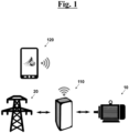
- the system for monitoring and analyzing electrical operating parameters of a load 10 in an electric network 20 comprises a smart socket 110 and a graphic interface 120, which can be placed near the smart socket 110 or in a remote position.
- the smart socket 110 comprises a voltage detection module arranged to measure a voltage value in the network, as an electric potential difference between the ends of the load 10 and a current detection module in the electric network 20 arranged to measure a current value adsorbed by the load 10, when the load 10 is connected to the electric network 20.
- the smart socket 110 also comprises a control unit connected to the voltage detection module and to the current detection module.
- control unit comprises an artificial intelligence such as, for example, an artificial neural network.
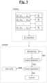
- control unit using the neural network, is arranged to carry out a preliminary step of training in which n events E i are classified corresponding to various types of disturbances or network operating anomalies that need to be classified during the following step of analysis.
- the training provides a first step where the neural network acquires a plurality of patterns p ij of predetermined current and/or voltage trends that are associated, according to the instructions provided, to respective events E i . More in detail, for each event E i the neural network acquires a number m i of patterns p ij of current and/or voltage trend that highlight the disturbance or anomaly represented by this event E i .
- the neural network On the basis of the set of m i patterns p ij associated with the event E i , the neural network is therefore capable of classifying this event E i and of extrapolating a plurality of characteristic parameters c ik distinguishing the patterns p ij of this set.
- characteristic parameters c ik chosen independently by the neural network, allow to evaluate whether a new current and/or voltage trend pattern acquired by the neural network is attributable or not to the same set and therefore is, possibly, attributable to the event E i associated with that set.
- the control unit After placing the smart socket 110 in series between the load 10 and the electric network 20, the control unit makes it possible to set the kind of diagnostic to carry out in the network.
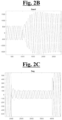
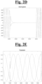
- Such current and voltage trends over time, as well as the current and voltage trends used in the training can be shown graphically by the waveforms, some examples of which are shown in Figs. 2 to 2E .
- the control unit then proceeds to carry out a comparison between the measured voltage and current trends and some predetermined voltage and current trends corresponding to the correct functioning of the network, to identify the presence of possible anomalous patterns.
- control unit proceeds, through the neural network, to the search of characteristic parameters c ik that allow to verify whether the anomalous pattern is attributable to one of the events E i classified during the step of training.
- the control unit confirms the presence of this event E i in the acquired voltage and/or current trend and proceeds to communicate this disturbance or anomaly, for example by means of a sound and/or acoustic alarm emitted by to smart socket 110 and/or by the graphic interface 120.
- the control unit confirms the presence of an unclassified event in the acquired voltage and/or current trend.
- control unit can then proceed in different ways, depending on the instructions provided during the step of training.
- control unit can simply issue an alarm that notifies the detection of an unclassified event, possibly requesting an update of the training step by inserting the unclassified event among the events being defined.
- control unit can proceed with the analysis of the electrical network 20 until a predetermined number of unclassified events associated with patterns having a certain number of common characteristic parameters c ik is reached.
- the commonality of these characteristic parameters c ik indicates in fact that the anomalous patterns detected do not show disturbances different from each other but all highlight the same disturbance and must therefore be included in a set associated with a new event E i to be classified.
- This classification operation of the new event E i can be carried out by an external operator, upon signaling from the control unit, or be carried out independently by the control unit itself.
- the system for monitoring and analyzing electrical parameters allows, thanks to the training step and the continuous updating of this step, an extremely higher capacity to recognize the disturbance or operating anomaly compared to prior art systems.
- the comparison between the detected voltage and/or current trends and the predetermined voltage and/or current trends can take place both numerically, processing the voltage and/or current values detected by the smart socket, and at graphic level, processing the spectrogram obtained from the detected voltage and/or current waveforms and verifying their correspondence with a predetermined spectrogram.
- control unit can make use, for example, of recurrent neural networks with the Long Short Term Memory algorithm which allows to process sequences of values and is divided into three main cells:
- the input signal is processed and an output is defined starting from the information deriving from the previous inputs and from the current one.
- control unit can for example make use of convolutional neural networks that recognize graphic patterns of the spectrograms of the sampled waveforms.
- control unit periodically sends the network diagnostics to the graphic interface 120, which includes both the operating status of the network and some quantities of interest derived from the voltage and current trends, such as the active power, the reactive power and phase shift (cos ⁇ ) of the network.
- control unit can send an alarm signal in case the network operating status is anomalous.
- figure 2 shows a waveform representing a trend over time of a three-phase voltage associated with a state of correct operation
- figures 2A to 2E show waveforms associated with states of malfunction. of the network.
Landscapes
- Engineering & Computer Science (AREA)
- Power Engineering (AREA)
- Physics & Mathematics (AREA)
- General Physics & Mathematics (AREA)
- Testing And Monitoring For Control Systems (AREA)
- Computer Networks & Wireless Communication (AREA)
- Remote Monitoring And Control Of Power-Distribution Networks (AREA)
Claims (11)
- System zur Überwachung und Analyse von elektrischen Betriebsparametern einer Last (10) in einem elektrischen Netzwerk (20), wobei das System eine intelligente Steckdose (110) umfasst, die angeordnet ist, um in Reihe zwischen der Last (10) und dem elektrischen Netzwerk (20) platziert zu sein, wobei die intelligente Steckdose (110) Folgendes umfasst:- ein Spannungserkennungsmodul, das konfiguriert ist, um einen Spannungswert in dem elektrischen Netzwerk (20) als elektrische Potenzialdifferenz zwischen den Enden der Last (10) zu messen;- ein Stromerkennungsmodul in dem elektrischen Netzwerk (20), das angeordnet ist, um einen Stromwert zu messen, der durch die Last (10) absorbiert wird, wenn die Last (10) mit dem elektrischen Netzwerk (20) verbunden ist;- eine Steuereinheit, die mit dem Spannungserkennungsmodul und dem Stromerkennungsmodul verbunden ist;wobei die Steuereinheit konfiguriert ist, um Folgendes durchzuführen:- eine periodische Erfassung, mit einer vorbestimmten Frequenz f , des Spannungswertes in dem elektrischen Netzwerk (20), um einen Spannungstrend im Zeitverlauf zu erhalten;- eine periodische Erfassung, mit einer vorbestimmten Frequenz f , des Stromwertes, der durch die Last (10) absorbiert wird, um einen Stromtrend im Zeitverlauf zu erhalten;wobei das System dadurch gekennzeichnet ist, dass die Steuereinheit ein neuronales Netzwerk umfasst, das angeordnet ist, um ein Training durchzuführen, das die folgenden Schritte umfasst:- Definition einer Anzahl n an Ereignissen Ei, wobei jedes Ereignis Ei eine Störung oder eine Betriebsanomalie des elektrischen Netzwerks (20) darstellt;- Zuordnung, zu jedem Ereignis Ei, einer Anzahl mi an Mustern pij von vorbestimmten Strom- und/oder Spannungstrends, wobei pij das j -te Muster angibt, das dem i-ten Ereignis Ei zugeordnet ist, mit i = 1,2,..., n und j = 1,2,..., mi, wodurch eine Anzahl n an klassifizierten Ereignissen Ei erhalten wird;- für jedes klassifizierte Ereignis Ei Extrapolation von charakteristischen Parametern cik , welche die Muster pij unterscheiden, die dem klassifizierten Ereignis Ei zugeordnet sind, wobei cik den k -ten charakteristischen Parameter des i-ten klassifizierten Ereignisses Ei angibt;und dass das neuronale Netzwerk auch angeordnet ist, um eine Analyse des Spannungs- und/oder Stromtrends durchzuführen, der durch die Steuereinheit erfasst wird, wobei die Analyse die folgenden Schritte umfasst:- Vergleich des erfassten Spannungs- und/oder Stromtrends mit vorbestimmten Spannungs- und/oder Stromtrends, die dem korrekten Betrieb des elektrischen Netzwerks (20) entsprechen;- Definition von möglichen anomalen Mustern in dem erfassten Spannungs- und/oder Stromtrend in Bezug auf die vorbestimmten Spannungs- und/oder Stromtrends;- im Falle von Identifizierung von zumindest einem anomalen Muster Suche nach den charakteristischen Parametern cik in dem oder jedem identifizierten anomalen Muster mit der Folge:- Bestätigung des Vorhandenseins des klassifizierten Ereignisses Ei in dem erfassten Spannungs- und/oder Stromtrend, falls das oder jedes identifizierte anomale Muster zumindest eine vorbestimmte Anzahl an charakteristischen Parametern cik eines klassifizierten Ereignisses Ei umfasst;- Bestätigung des Vorhandenseins eines nicht klassifizierten Ereignisses in dem erfassten Spannungs- und/oder Stromtrend, falls das oder jedes identifizierte Muster nicht zumindest die vorbestimmte Anzahl an charakteristischen Parametern cik eines klassifizierten Ereignisses Ei umfasst.
- System zur Überwachung und Analyse von elektrischen Betriebsparametern einer Last (10) in einem elektrischen Netzwerk (20) nach Anspruch 1, wobei im Falle von Bestätigung des Vorhandenseins des klassifizierten Ereignisses Ei in dem erfassten Spannungs- und/oder Stromtrend die Steuereinheit angeordnet ist, um einen entsprechenden Alarm vom akustischen und/oder optischen Typ zu erzeugen, der den Typ des identifizierten klassifizierten Ereignisses Ei zeigt.
- System zur Überwachung und Analyse von elektrischen Betriebsparametern einer Last (10) in einem elektrischen Netzwerk (20) nach Anspruch 1, wobei im Falle von Bestätigung des Vorhandenseins eines nicht klassifizierten Ereignisses in dem erfassten Spannungs- und/oder Stromtrend die Steuereinheit angeordnet ist, um einen entsprechenden Alarm vom akustischen und/oder optischen Typ zu erzeugen.
- System zur Überwachung und Analyse von elektrischen Betriebsparametern einer Last (10) in einem elektrischen Netzwerk (20) nach Anspruch 1, wobei beim Erreichen einer vorbestimmten Anzahl an Bestätigungen von nicht klassifizierten Ereignissen die Steuereinheit angeordnet ist, um eine Aktualisierung des Schrittes zur Definition von Ereignissen Ei anzufordern.
- System zur Überwachung und Analyse von elektrischen Betriebsparametern einer Last (10) in einem elektrischen Netzwerk (20) nach Anspruch 1, wobei beim Erreichen einer vorbestimmten Anzahl an Bestätigungen von nicht klassifizierten Ereignissen, die Mustern zugeordnet sind, die eine bestimmte Anzahl an gemeinsamen charakteristischen Parametern cik zwischen sich aufweisen, die Steuereinheit angeordnet ist, um die Muster einem klassifizierten Ereignis zuzuordnen und/oder um die Definition eines neuen klassifizierten Ereignisses anzufordern, das es den Mustern zuordnet.
- System zur Überwachung und Analyse von elektrischen Betriebsparametern einer Last (10) in einem elektrischen Netzwerk (20) nach Anspruch 1, wobei die Steuereinheit angeordnet ist, um ein Spektrogramm einer Wellenform der Spannung, das angeordnet ist, um den erfassten Spannungstrend darzustellen, und/oder ein Spektrogramm einer Wellenform des Stroms, das angeordnet ist, um den erfassten Stromtrend darzustellen, zu erzeugen, und wobei der Vergleich des erfassten Spannungs- und/oder Stromtrends mit den vorbestimmten Spannungs- und/oder Stromtrends durch eine Suche nach grafischer Übereinstimmung zwischen dem Spektrogramm der Wellenform des erfassten Spannungs- und/oder Stromtrends mit Spektrogrammen von Wellenformen, die angeordnet sind, um den vorbestimmten Spannungs- und/oder Stromtrend darzustellen, erfolgt.
- System zur Überwachung und Analyse von elektrischen Betriebsparametern einer Last (10) in einem elektrischen Netzwerk (20) nach einem der vorhergehenden Ansprüche, wobei die Steuereinheit angeordnet ist, um eine Berechnung einer Vielzahl von physikalischen Mengen von Interesse durchzuführen, ausgehend von dem erfassten Spannungs- und/oder Stromtrend.
- System zur Überwachung und Analyse von elektrischen Betriebsparametern einer Last (10) in einem elektrischen Netzwerk (20) nach einem der vorhergehenden Ansprüche, wobei eine grafische Schnittstelle (120) auch bereitgestellt ist, die angeordnet ist, um einem Benutzer das mögliche Vorhandensein von klassifizierten Ereignissen Ei und/oder von nicht klassifizierten Ereignissen zu zeigen.
- System zur Überwachung und Analyse von elektrischen Betriebsparametern einer Last (10) in einem elektrischen Netzwerk (20) nach einem der vorhergehenden Ansprüche, wobei die Steuereinheit auch angeordnet ist, um eine Filterung des erfassten Spannungs- und/oder Stromtrends durchzuführen, um Signalrauschen zu entfernen.
- System zur Überwachung und Analyse von elektrischen Betriebsparametern einer Last (10) in einem elektrischen Netzwerk (20) nach einem der vorhergehenden Ansprüche, wobei die periodischen Erfassungen der Werte von Spannung und von Strom mit Frequenz f = 10kHz durchgeführt werden.
- Verfahren zur Überwachung und Analyse von elektrischen Betriebsparametern einer Last (10) in einem elektrischen Netzwerk (20), wobei das Verfahren die folgenden Schritte umfasst:- Voranordnung einer intelligenten Steckdose (110), umfassend:wobei das Verfahren dadurch gekennzeichnet ist, dass es auch die folgenden Schritte umfasst:- ein Spannungserkennungsmodul, das angeordnet ist, um einen Spannungswert in dem elektrischen Netzwerk (20) als elektrische Potenzialdifferenz zwischen den Enden der Last (10) zu messen;- ein Stromerkennungsmodul in dem elektrischen Netzwerk (20), das angeordnet ist, um einen Stromwert zu messen, der durch die Last (10) absorbiert wird, wenn die Last (10) mit dem elektrischen Netzwerk (20) verbunden ist;- eine Steuereinheit, die mit dem Spannungserkennungsmodul und dem Stromerkennungsmodul verbunden ist, wobei die Steuereinheit ein neuronales Netzwerk umfasst;- Definition einer Anzahl n an Ereignissen Ei, wobei jedes Ereignis Ei eine Störung oder eine Betriebsanomalie des elektrischen Netzwerks (20) darstellt;- Zuordnung, zu jedem Ereignis Ei , einer Anzahl mi an Mustern pij von vorbestimmten Strom- und/oder Spannungstrends, wobei pij das j -te Muster angibt, das dem i-ten Ereignis Ei zugeordnet ist, mit i = 1,2,... , n und j = 1,2, ..., mi, wodurch eine Anzahl n an klassifizierten Ereignissen Ei erhalten wird;- für jedes klassifizierte Ereignis Ei Extrapolation von charakteristischen Parametern cik , welche die Muster pij unterscheiden, die dem klassifizierten Ereignis Ei zugeordnet sind, wobei cik den k-ten charakteristischen Parameter des i-ten klassifizierten Ereignisses Ei angibt;- Anordnen der intelligenten Steckdose (110) in Reihe zwischen der Last (10) und dem elektrischen Netzwerk (20);- periodische Erfassung, mit einer vorbestimmten Frequenz f , des Spannungswertes in dem elektrischen Netzwerk (20), wodurch ein Spannungstrend im Zeitverlauf erhalten wird;- periodische Erfassung, mit einer vorbestimmten Frequenz f , des Stromwertes, der durch die Last (10) absorbiert wird, wodurch ein Stromtrend im Zeitverlauf erhalten wird;- Vergleich des erfassten Spannungs- und/oder Stromtrends mit vorbestimmten Spannungs- und/oder Stromtrends, die dem korrekten Betrieb des elektrischen Netzwerks (20) entsprechen;- Definition von möglichen anomalen Mustern in dem erfassten Spannungs- und/oder Stromtrend in Bezug auf die vorbestimmten Spannungs- und/oder Stromtrends;- im Falle von Identifizierung von zumindest einem anomalen Muster Suche nach den charakteristischen Parametern cik in dem oder jedem identifizierten anomalen Muster mit der Folge:- Bestätigung des Vorhandenseins des klassifizierten Ereignisses Ei in dem erfassten Spannungs- und/oder Stromtrend, falls das oder jedes identifizierte anomale Muster zumindest eine vorbestimmte Anzahl an charakteristischen Parametern cik eines klassifizierten Ereignisses Ei umfasst;- Bestätigung des Vorhandenseins eines nicht klassifizierten Ereignisses in dem erfassten Spannungs- und/oder Stromtrend, falls das oder jedes identifizierte Muster nicht zumindest die vorbestimmte Anzahl an charakteristischen Parametern cik eines klassifizierten Ereignisses Ei umfasst.
Applications Claiming Priority (2)
| Application Number | Priority Date | Filing Date | Title |
|---|---|---|---|
| IT102019000025855A IT201900025855A1 (it) | 2019-12-31 | 2019-12-31 | Sistema per il monitoraggio e l’analisi di parametri elettrici |
| PCT/IB2020/062594 WO2021137193A1 (en) | 2019-12-31 | 2020-12-31 | System for monitoring and analyzing electric parameters |
Publications (3)
| Publication Number | Publication Date |
|---|---|
| EP4085262A1 EP4085262A1 (de) | 2022-11-09 |
| EP4085262B1 true EP4085262B1 (de) | 2024-09-04 |
| EP4085262C0 EP4085262C0 (de) | 2024-09-04 |
Family
ID=70228651
Family Applications (1)
| Application Number | Title | Priority Date | Filing Date |
|---|---|---|---|
| EP20848725.6A Active EP4085262B1 (de) | 2019-12-31 | 2020-12-31 | System zur überwachung und analyse von elektrischen parametern |
Country Status (4)
| Country | Link |
|---|---|
| US (1) | US12253548B2 (de) |
| EP (1) | EP4085262B1 (de) |
| IT (1) | IT201900025855A1 (de) |
| WO (1) | WO2021137193A1 (de) |
Families Citing this family (3)
| Publication number | Priority date | Publication date | Assignee | Title |
|---|---|---|---|---|
| CN117826966B (zh) * | 2024-03-06 | 2024-06-18 | 北京比格凯特科技有限公司 | 一种双显卡模块的电源控制模块 |
| CN120302188B (zh) * | 2025-03-26 | 2025-11-04 | 青岛华烁高科信息有限公司 | 一种智能电能表远程监控装置 |
| CN120822163B (zh) * | 2025-09-18 | 2025-12-02 | 国网山西省电力公司超高压变电分公司 | 基于运行态势感知的站用电负载特征识别系统 |
Family Cites Families (11)
| Publication number | Priority date | Publication date | Assignee | Title |
|---|---|---|---|---|
| CN1969191A (zh) * | 2003-07-09 | 2007-05-23 | 伊斯拉-裘克电子有限公司 | 检测电路故障的系统、设备及方法 |
| CN100570388C (zh) * | 2003-12-18 | 2009-12-16 | 株式会社Lg化学 | 使用神经网络评估电池的充电状态的设备和方法 |
| WO2010070899A1 (ja) * | 2008-12-17 | 2010-06-24 | パナソニック株式会社 | 電力変換回路 |
| US8756181B2 (en) * | 2011-11-28 | 2014-06-17 | Eaton Corporation | System and method employing a self-organizing map load feature database to identify electric load types of different electric loads |
| JP2017515449A (ja) * | 2014-04-14 | 2017-06-08 | パワー モニターズ インコーポレイテッド | クラウドベースの電力品質モニタのための方法及び装置 |
| GB2531787A (en) * | 2014-10-31 | 2016-05-04 | Isra-Juk Electronics Ltd | System and method for detection of electrical faults in an electrical network |
| US9866021B2 (en) * | 2014-12-09 | 2018-01-09 | Eaton Corporation | Load power device, system and method of load control and management employing load identification |
| JP6243385B2 (ja) * | 2015-10-19 | 2017-12-06 | ファナック株式会社 | モータ電流制御における補正値を学習する機械学習装置および方法ならびに該機械学習装置を備えた補正値計算装置およびモータ駆動装置 |
| US20170271915A1 (en) * | 2016-03-16 | 2017-09-21 | Why Energy, LLC | Energy Demand Monitoring System and Smart micro-Grid Controller |
| IT201600123334A1 (it) | 2016-12-05 | 2018-06-05 | Univ Degli Studi Di Firenze | Presa intelligente e sistema di monitoraggio e controllo utilizzante detta presa |
| GB2560032A (en) * | 2017-02-28 | 2018-08-29 | Green Running Ltd | An appliance operation signal processing system and method |
-
2019
- 2019-12-31 IT IT102019000025855A patent/IT201900025855A1/it unknown
-
2020
- 2020-12-31 WO PCT/IB2020/062594 patent/WO2021137193A1/en not_active Ceased
- 2020-12-31 US US17/790,051 patent/US12253548B2/en active Active
- 2020-12-31 EP EP20848725.6A patent/EP4085262B1/de active Active
Also Published As
| Publication number | Publication date |
|---|---|
| EP4085262A1 (de) | 2022-11-09 |
| US12253548B2 (en) | 2025-03-18 |
| IT201900025855A1 (it) | 2021-07-01 |
| WO2021137193A1 (en) | 2021-07-08 |
| EP4085262C0 (de) | 2024-09-04 |
| US20230054387A1 (en) | 2023-02-23 |
Similar Documents
| Publication | Publication Date | Title |
|---|---|---|
| CN118884129B (zh) | 基于人工智能的配电网故障定位方法和存储介质 | |
| EP4085262B1 (de) | System zur überwachung und analyse von elektrischen parametern | |
| US11656589B2 (en) | Systems and methods for automatic power topology discovery | |
| CN107111844B (zh) | 用于选择网格动作以改善网格结果的系统和方法 | |
| JP6298214B2 (ja) | ユーティリティグリッド内での信号注入テストパターンの予想効用を最大化するためのシステム及び方法 | |
| CN117639251A (zh) | 一种高压开关柜智能在线监测系统 | |
| CN118114019A (zh) | 一种基于数据分析的配电网拓扑自动识别方法及系统 | |
| JP6599428B2 (ja) | グリッドの異常重大度を表す現場でのセンサ応答データパターンを分類するためのシステム及び方法 | |
| Dehaghani et al. | Ai applications for power quality issues in distribution systems: A systematic review | |
| WO2024003367A1 (en) | Method and device for forecasting upcoming faults in power systems | |
| Bhuiyan et al. | A deep learning through DBN enabled transmission line fault transient classification framework for multimachine microgrid systems | |
| US12362565B2 (en) | Resilient decision systems and methods | |
| US20230153389A1 (en) | Systems and methods for automatically identifying, analyzing and reducing extraneous waveform captures | |
| CN118861933A (zh) | 屏蔽检修异常报警信息的方法和系统 | |
| Ding et al. | Automatic distribution network reconfiguration: An event-driven approach | |
| Gopinathan et al. | Synchrophasor forensics: tracking spatiotemporal anomalies and diagnosing grid frequency events with machine learning for enhanced situational awareness | |
| Najar et al. | Intelligent islanding detection scheme for microgrid based on deep learning and wavelet transform | |
| EP4231198A1 (de) | Verfahren zum erzeugen einer signalverarbeitungslogik, vorrichtung zum steuern, überwachen und/oder analysieren eines physikalischen werts und elektrisches energiesystem | |
| Viereck et al. | Driving reliability with machine learning and improving operation by digitalization of power transformers | |
| Sinha et al. | A New Approach to Detect Power Quality Disturbances in Smart Cities Using Scaling-Based Chirplet Transform with Strategically Placed Smart Meters | |
| Saiprakash et al. | Fault Diagnosis in Micro Grid Using Wavelet Transform in Combination with Machine Learning | |
| TP et al. | Optimizing Fault Detection in Electrical Grids Through Neural Network Models | |
| Daggupati | Power quality disturbance classification in ieee 9-bus system using stft and deep learning | |
| Gorjani et al. | Application of optimized deterministic methods in long-term power quality | |
| Streubel | Fingerprint Approach for the Characterization and Mitigation of Supraharmonic Distortion from Electric Vehicles |
Legal Events
| Date | Code | Title | Description |
|---|---|---|---|
| STAA | Information on the status of an ep patent application or granted ep patent |
Free format text: STATUS: UNKNOWN |
|
| STAA | Information on the status of an ep patent application or granted ep patent |
Free format text: STATUS: THE INTERNATIONAL PUBLICATION HAS BEEN MADE |
|
| PUAI | Public reference made under article 153(3) epc to a published international application that has entered the european phase |
Free format text: ORIGINAL CODE: 0009012 |
|
| STAA | Information on the status of an ep patent application or granted ep patent |
Free format text: STATUS: REQUEST FOR EXAMINATION WAS MADE |
|
| 17P | Request for examination filed |
Effective date: 20220728 |
|
| AK | Designated contracting states |
Kind code of ref document: A1 Designated state(s): AL AT BE BG CH CY CZ DE DK EE ES FI FR GB GR HR HU IE IS IT LI LT LU LV MC MK MT NL NO PL PT RO RS SE SI SK SM TR |
|
| DAV | Request for validation of the european patent (deleted) | ||
| DAX | Request for extension of the european patent (deleted) | ||
| GRAP | Despatch of communication of intention to grant a patent |
Free format text: ORIGINAL CODE: EPIDOSNIGR1 |
|
| STAA | Information on the status of an ep patent application or granted ep patent |
Free format text: STATUS: GRANT OF PATENT IS INTENDED |
|
| INTG | Intention to grant announced |
Effective date: 20240328 |
|
| GRAS | Grant fee paid |
Free format text: ORIGINAL CODE: EPIDOSNIGR3 |
|
| GRAA | (expected) grant |
Free format text: ORIGINAL CODE: 0009210 |
|
| STAA | Information on the status of an ep patent application or granted ep patent |
Free format text: STATUS: THE PATENT HAS BEEN GRANTED |
|
| AK | Designated contracting states |
Kind code of ref document: B1 Designated state(s): AL AT BE BG CH CY CZ DE DK EE ES FI FR GB GR HR HU IE IS IT LI LT LU LV MC MK MT NL NO PL PT RO RS SE SI SK SM TR |
|
| REG | Reference to a national code |
Ref country code: GB Ref legal event code: FG4D |
|
| REG | Reference to a national code |
Ref country code: CH Ref legal event code: EP |
|
| REG | Reference to a national code |
Ref country code: IE Ref legal event code: FG4D |
|
| REG | Reference to a national code |
Ref country code: DE Ref legal event code: R096 Ref document number: 602020037281 Country of ref document: DE |
|
| U01 | Request for unitary effect filed |
Effective date: 20241002 |
|
| U07 | Unitary effect registered |
Designated state(s): AT BE BG DE DK EE FI FR IT LT LU LV MT NL PT RO SE SI Effective date: 20241029 |
|
| PG25 | Lapsed in a contracting state [announced via postgrant information from national office to epo] |
Ref country code: NO Free format text: LAPSE BECAUSE OF FAILURE TO SUBMIT A TRANSLATION OF THE DESCRIPTION OR TO PAY THE FEE WITHIN THE PRESCRIBED TIME-LIMIT Effective date: 20241204 |
|
| PG25 | Lapsed in a contracting state [announced via postgrant information from national office to epo] |
Ref country code: GR Free format text: LAPSE BECAUSE OF FAILURE TO SUBMIT A TRANSLATION OF THE DESCRIPTION OR TO PAY THE FEE WITHIN THE PRESCRIBED TIME-LIMIT Effective date: 20241205 Ref country code: PL Free format text: LAPSE BECAUSE OF FAILURE TO SUBMIT A TRANSLATION OF THE DESCRIPTION OR TO PAY THE FEE WITHIN THE PRESCRIBED TIME-LIMIT Effective date: 20240904 |
|
| PG25 | Lapsed in a contracting state [announced via postgrant information from national office to epo] |
Ref country code: HR Free format text: LAPSE BECAUSE OF FAILURE TO SUBMIT A TRANSLATION OF THE DESCRIPTION OR TO PAY THE FEE WITHIN THE PRESCRIBED TIME-LIMIT Effective date: 20240904 |
|
| PG25 | Lapsed in a contracting state [announced via postgrant information from national office to epo] |
Ref country code: ES Free format text: LAPSE BECAUSE OF FAILURE TO SUBMIT A TRANSLATION OF THE DESCRIPTION OR TO PAY THE FEE WITHIN THE PRESCRIBED TIME-LIMIT Effective date: 20240904 Ref country code: RS Free format text: LAPSE BECAUSE OF FAILURE TO SUBMIT A TRANSLATION OF THE DESCRIPTION OR TO PAY THE FEE WITHIN THE PRESCRIBED TIME-LIMIT Effective date: 20241204 |
|
| U20 | Renewal fee for the european patent with unitary effect paid |
Year of fee payment: 5 Effective date: 20241223 |
|
| PG25 | Lapsed in a contracting state [announced via postgrant information from national office to epo] |
Ref country code: RS Free format text: LAPSE BECAUSE OF FAILURE TO SUBMIT A TRANSLATION OF THE DESCRIPTION OR TO PAY THE FEE WITHIN THE PRESCRIBED TIME-LIMIT Effective date: 20241204 Ref country code: PL Free format text: LAPSE BECAUSE OF FAILURE TO SUBMIT A TRANSLATION OF THE DESCRIPTION OR TO PAY THE FEE WITHIN THE PRESCRIBED TIME-LIMIT Effective date: 20240904 Ref country code: NO Free format text: LAPSE BECAUSE OF FAILURE TO SUBMIT A TRANSLATION OF THE DESCRIPTION OR TO PAY THE FEE WITHIN THE PRESCRIBED TIME-LIMIT Effective date: 20241204 Ref country code: HR Free format text: LAPSE BECAUSE OF FAILURE TO SUBMIT A TRANSLATION OF THE DESCRIPTION OR TO PAY THE FEE WITHIN THE PRESCRIBED TIME-LIMIT Effective date: 20240904 Ref country code: GR Free format text: LAPSE BECAUSE OF FAILURE TO SUBMIT A TRANSLATION OF THE DESCRIPTION OR TO PAY THE FEE WITHIN THE PRESCRIBED TIME-LIMIT Effective date: 20241205 Ref country code: ES Free format text: LAPSE BECAUSE OF FAILURE TO SUBMIT A TRANSLATION OF THE DESCRIPTION OR TO PAY THE FEE WITHIN THE PRESCRIBED TIME-LIMIT Effective date: 20240904 |
|
| PG25 | Lapsed in a contracting state [announced via postgrant information from national office to epo] |
Ref country code: IS Free format text: LAPSE BECAUSE OF FAILURE TO SUBMIT A TRANSLATION OF THE DESCRIPTION OR TO PAY THE FEE WITHIN THE PRESCRIBED TIME-LIMIT Effective date: 20250104 |
|
| PG25 | Lapsed in a contracting state [announced via postgrant information from national office to epo] |
Ref country code: SM Free format text: LAPSE BECAUSE OF FAILURE TO SUBMIT A TRANSLATION OF THE DESCRIPTION OR TO PAY THE FEE WITHIN THE PRESCRIBED TIME-LIMIT Effective date: 20240904 |
|
| PG25 | Lapsed in a contracting state [announced via postgrant information from national office to epo] |
Ref country code: CZ Free format text: LAPSE BECAUSE OF FAILURE TO SUBMIT A TRANSLATION OF THE DESCRIPTION OR TO PAY THE FEE WITHIN THE PRESCRIBED TIME-LIMIT Effective date: 20240904 |
|
| PG25 | Lapsed in a contracting state [announced via postgrant information from national office to epo] |
Ref country code: SK Free format text: LAPSE BECAUSE OF FAILURE TO SUBMIT A TRANSLATION OF THE DESCRIPTION OR TO PAY THE FEE WITHIN THE PRESCRIBED TIME-LIMIT Effective date: 20240904 |
|
| PG25 | Lapsed in a contracting state [announced via postgrant information from national office to epo] |
Ref country code: MC Free format text: LAPSE BECAUSE OF FAILURE TO SUBMIT A TRANSLATION OF THE DESCRIPTION OR TO PAY THE FEE WITHIN THE PRESCRIBED TIME-LIMIT Effective date: 20240904 |
|
| PLBE | No opposition filed within time limit |
Free format text: ORIGINAL CODE: 0009261 |
|
| STAA | Information on the status of an ep patent application or granted ep patent |
Free format text: STATUS: NO OPPOSITION FILED WITHIN TIME LIMIT |
|
| REG | Reference to a national code |
Ref country code: CH Ref legal event code: PL |
|
| 26N | No opposition filed |
Effective date: 20250605 |
|
| GBPC | Gb: european patent ceased through non-payment of renewal fee |
Effective date: 20241231 |
|
| PG25 | Lapsed in a contracting state [announced via postgrant information from national office to epo] |
Ref country code: GB Free format text: LAPSE BECAUSE OF NON-PAYMENT OF DUE FEES Effective date: 20241231 |
|
| PG25 | Lapsed in a contracting state [announced via postgrant information from national office to epo] |
Ref country code: CH Free format text: LAPSE BECAUSE OF NON-PAYMENT OF DUE FEES Effective date: 20241231 |
|
| PG25 | Lapsed in a contracting state [announced via postgrant information from national office to epo] |
Ref country code: IE Free format text: LAPSE BECAUSE OF NON-PAYMENT OF DUE FEES Effective date: 20241231 |
|
| U20 | Renewal fee for the european patent with unitary effect paid |
Year of fee payment: 6 Effective date: 20251229 |