EP4084260A1 - Procédé pour fournir de l'énergie à un parc éolien en condition de vent faible - Google Patents
Procédé pour fournir de l'énergie à un parc éolien en condition de vent faible Download PDFInfo
- Publication number
- EP4084260A1 EP4084260A1 EP21170870.6A EP21170870A EP4084260A1 EP 4084260 A1 EP4084260 A1 EP 4084260A1 EP 21170870 A EP21170870 A EP 21170870A EP 4084260 A1 EP4084260 A1 EP 4084260A1
- Authority
- EP
- European Patent Office
- Prior art keywords
- string
- wind
- wind turbine
- circuit breaker
- power generator
- Prior art date
- Legal status (The legal status is an assumption and is not a legal conclusion. Google has not performed a legal analysis and makes no representation as to the accuracy of the status listed.)
- Withdrawn
Links
Images


Classifications
-
- H—ELECTRICITY
- H02—GENERATION; CONVERSION OR DISTRIBUTION OF ELECTRIC POWER
- H02J—CIRCUIT ARRANGEMENTS OR SYSTEMS FOR SUPPLYING OR DISTRIBUTING ELECTRIC POWER; SYSTEMS FOR STORING ELECTRIC ENERGY
- H02J3/00—Circuit arrangements for ac mains or ac distribution networks
- H02J3/38—Arrangements for parallely feeding a single network by two or more generators, converters or transformers
- H02J3/46—Controlling of the sharing of output between the generators, converters, or transformers
- H02J3/48—Controlling the sharing of the in-phase component
-
- H—ELECTRICITY
- H02—GENERATION; CONVERSION OR DISTRIBUTION OF ELECTRIC POWER
- H02J—CIRCUIT ARRANGEMENTS OR SYSTEMS FOR SUPPLYING OR DISTRIBUTING ELECTRIC POWER; SYSTEMS FOR STORING ELECTRIC ENERGY
- H02J3/00—Circuit arrangements for ac mains or ac distribution networks
- H02J3/38—Arrangements for parallely feeding a single network by two or more generators, converters or transformers
- H02J3/381—Dispersed generators
-
- H—ELECTRICITY
- H02—GENERATION; CONVERSION OR DISTRIBUTION OF ELECTRIC POWER
- H02J—CIRCUIT ARRANGEMENTS OR SYSTEMS FOR SUPPLYING OR DISTRIBUTING ELECTRIC POWER; SYSTEMS FOR STORING ELECTRIC ENERGY
- H02J3/00—Circuit arrangements for ac mains or ac distribution networks
- H02J3/38—Arrangements for parallely feeding a single network by two or more generators, converters or transformers
- H02J3/46—Controlling of the sharing of output between the generators, converters, or transformers
- H02J3/50—Controlling the sharing of the out-of-phase component
-
- H—ELECTRICITY
- H02—GENERATION; CONVERSION OR DISTRIBUTION OF ELECTRIC POWER
- H02J—CIRCUIT ARRANGEMENTS OR SYSTEMS FOR SUPPLYING OR DISTRIBUTING ELECTRIC POWER; SYSTEMS FOR STORING ELECTRIC ENERGY
- H02J2300/00—Systems for supplying or distributing electric power characterised by decentralized, dispersed, or local generation
- H02J2300/20—The dispersed energy generation being of renewable origin
- H02J2300/28—The renewable source being wind energy
-
- Y—GENERAL TAGGING OF NEW TECHNOLOGICAL DEVELOPMENTS; GENERAL TAGGING OF CROSS-SECTIONAL TECHNOLOGIES SPANNING OVER SEVERAL SECTIONS OF THE IPC; TECHNICAL SUBJECTS COVERED BY FORMER USPC CROSS-REFERENCE ART COLLECTIONS [XRACs] AND DIGESTS
- Y02—TECHNOLOGIES OR APPLICATIONS FOR MITIGATION OR ADAPTATION AGAINST CLIMATE CHANGE
- Y02E—REDUCTION OF GREENHOUSE GAS [GHG] EMISSIONS, RELATED TO ENERGY GENERATION, TRANSMISSION OR DISTRIBUTION
- Y02E10/00—Energy generation through renewable energy sources
- Y02E10/70—Wind energy
- Y02E10/72—Wind turbines with rotation axis in wind direction
-
- Y—GENERAL TAGGING OF NEW TECHNOLOGICAL DEVELOPMENTS; GENERAL TAGGING OF CROSS-SECTIONAL TECHNOLOGIES SPANNING OVER SEVERAL SECTIONS OF THE IPC; TECHNICAL SUBJECTS COVERED BY FORMER USPC CROSS-REFERENCE ART COLLECTIONS [XRACs] AND DIGESTS
- Y02—TECHNOLOGIES OR APPLICATIONS FOR MITIGATION OR ADAPTATION AGAINST CLIMATE CHANGE
- Y02E—REDUCTION OF GREENHOUSE GAS [GHG] EMISSIONS, RELATED TO ENERGY GENERATION, TRANSMISSION OR DISTRIBUTION
- Y02E10/00—Energy generation through renewable energy sources
- Y02E10/70—Wind energy
- Y02E10/76—Power conversion electric or electronic aspects
Definitions
- the present invention relates to a method of supplying power to an electrically islanded wind farm in a low wind condition, and to such a wind farm.
- a conventional wind farm comprises a plurality of wind turbines which are connected in parallel to each other in a plurality of strings, which can also be referred as arrays.
- a power generator is connected to the wind farm to supply electric power to the wind turbines in the strings when there is no grid connection available.
- a control device is provided which is configured to operate the wind farm in several operation modes.
- an electrically isolated wind farm can perform a so-called black start (or self-energising mode) itself or remain energised with the aid of a relatively small additional power source.
- an additional power source may take the form of a diesel, or other fuel powered generator, a photovoltaic or energy storage device, or a combination of some or all of the above.
- the wind turbines When isolated or islanded from an electrical grid, the wind turbines can maintain the AC frequency and voltage within the island by exchanging active and reactive power with via passive components such as cables and transformers. However, when the wind conditions are low, the wind turbines are not able to supply active power, and an additional power source is necessary.
- the wind turbine power converters operate in a voltage support mode (Vmode), which could also be called reactive power support mode, where the whole electrical current capability of the wind turbine converters is available for exporting and/or importing reactive power.
- Vmode voltage support mode
- the later situation could allow the wind farm to be a key future contributor in the black start of the wider electrical grid, where large transformers and transmission lines can be back energised from the wind farm using the full capacity of the wind turbine power converters.
- a method of supplying power to a wind farm comprises a plurality of wind turbines which are connected n parallel to each other in a first string, wherein respective cable section circuit breakers are arranged between adjacent wind turbines of the first string; and a power generator which is connected to a first wind turbine of the first string, wherein a first string circuit breaker is arranged in a line between the power generator and the first wind turbine.
- the method comprises the following operation modes in a low wind condition, where a wind speed falls below a threshold value: a first operation mode where the first string circuit breaker is closed to supply active power from the power generator to the first wind turbine and to supply or consume reactive power from or to the power generator to or from a passive cable and/or transformer between the power generator and the first wind turbine, while the remaining cable section circuit breakers in the first string are opened; and a second operation mode after the first operation mode, where a cable section circuit breaker between the first wind turbine and an adjacent second wind turbine is closed to supply active power from the power generator to the first and second wind turbines and to supply or consume reactive power from or to the first wind turbine to or from the passive cable and/or transformer between the first wind turbine and the second wind turbine, while the remaining cable section circuit breakers in the first string are opened.
- the passive components of the cables and transformers between the power generator and first wind turbine require an exchange of reactive power with the power generator.
- exchange can be used because cables tend to produce reactive power, and transformers tend to consume reactive power.
- the production and consumption of each component tends not to be balanced, and therefore the power generator is useful to compensate for the difference by either consuming or supplying.
- the cable reactive power production tends to dominate the consumption of the transformers, and therefore the power generator must consume reactive power to achieve the balance.
- the wind turbines are required to assist in making this balance also by consuming reactive power as the power generator would not be sized to be able to do this.
- the reactive power flow in a wind farm when wind is low, will dominate the active power flow which supplies auxiliaries of the wind turbines and covers power losses.
- the second operating mode is also used to sequentially energize wind turbines of the first string other than the first and second wind turbines.
- the wind farm comprises n wind turbines in the first string, wherein the first wind turbine is the most upstream wind turbine in the first string and the n-th wind turbine is the most downstream wind turbine in the first string.
- the method comprises sequentially closing the cable section circuit breakers starting out from the cable section circuit breaker between the first and second wind turbines up to a cable section circuit breaker between the n-th wind turbine and the n-1-th wind turbine, thereby sequentially supplying active power from the power generator to the first to n-th wind turbines and sequentially supplying or consuming reactive power from or to the wind turbines to or from a respective downstream passive cable and/or transformer.
- the n wind turbines of the first string can be used to energize the m wind turbines of the second string.
- a minimum number of energized wind turbines can act alongside the power generator to energize a grid line that comprises a grid transformer and transmission lines.
- the power generator will supply active power to the wind turbines and the grid line, whereas the wind turbines will supply or consume reactive power to or from the grid line to control the voltage.
- the wind farm further comprises at least one further plurality of wind turbines which are connected in parallel to each other in at least one further string, wherein respective cable section circuit breakers are arranged between adjacent wind turbines of the at least one further string; wherein the power generator is connected to a first wind turbine of the at least one further string, wherein at least one further string circuit breaker is arranged in a line between the power generator and the first wind turbine of the at least one further string.
- the method further comprises, after closing the wind turbine circuit breaker between the n-th wind turbine and the n-1-th wind turbine of the first string, performing the first and second operation modes in the at least one further string in the same manner as in the first string as described above, and/or performing sequentially closing the cable section circuit breakers in the at least one further string in the same manner as in the first string as described above; wherein reactive power is also supplied or consumed from or to the wind turbines of the first string to or from the passive cable and/or transformer of the further string.
- the wind farm further comprises a grid supply line which is connected via a grid supply line circuit breaker to a bus bar between the first wind turbine and the power generator, wherein, if a minimum number of wind turbines in the wind farm is supplied by active power, the grid supply line circuit breaker is closed to supply active power and supply or consume reactive power from or to the bus bar between the first wind turbine and the power generator to or from the grid supply line.
- the power generator could be connected to any point in the wind farm and will be located according to site conditions, depending on where there is an available connection point.
- the grid supply line is connected to a grid via a grid circuit breaker, at its distant end, wherein the grid supply line comprises, between the grid supply line circuit breaker and the grid circuit breaker, a grid transformer and/or a transmission line, wherein the grid circuit breaker is opened when performing the above-described steps.
- the wind farm comprises at least one of the following: each wind turbine in the first string comprises a corresponding wind turbine connection circuit breaker to connect or interrupt the respective wind turbine to or from the first string; each wind turbine in the at least one further string comprises a corresponding wind turbine circuit breaker to connect or interrupt the respective wind turbine to or from the at least one other string; and the power generator is connected to the first string via a power generator circuit breaker, wherein the power generator circuit breaker is closed in the low wind condition and opened in conditions other than the low wind condition.
- a wind farm comprises a plurality of wind turbines which are connected in parallel to each other in a first string, wherein respective cable section circuit breakers are arranged between adjacent wind turbines of the first string; a power generator which is connected to a first wind turbine of the first string, wherein a first string circuit breaker is arranged in a line between the power generator and the first wind turbine; and a control device which is configured to operate the wind farm in the following operation modes in a low wind condition, where a wind speed falls below a threshold value: a first operation mode where the first string circuit breaker is closed to supply active power from the power generator to the first wind turbine and to supply or consume reactive power from or to the power generator to or from the passive cable and/or transformer between the power generator and the first wind turbine, while the remaining cable section circuit breakers in the first string are opened; and a second operation mode after the first operation mode, where a cable section circuit breaker between the first wind turbine and an adjacent second wind turbine is closed to supply
- a different control device may be used to close these circuit breakers as it may be owned under the regime of a grid operator instead of a wind farm operator.
- the wind farm comprises n wind turbines in the first string, wherein the first wind turbine is the most upstream wind turbine in the first string and the n-th wind turbine is the most downstream wind turbine in the first string.
- the control device is configured to sequentially close the cable section circuit breakers starting out from the cable section circuit breaker between the first and second wind turbines up to a cable section circuit breaker between the n-th wind turbine and the n-1-th wind turbine, thereby sequentially supplying active power from the power generator to the first to n-th wind turbines and sequentially supplying or consuming reactive power from or to the wind turbines to or from a respective downstream passive cable and/or transformer.
- the wind farm further comprises at least one further plurality of wind turbines which are connected in parallel to each other in at least one further string, wherein respective cable section circuit breakers are arranged between adjacent wind turbines of the at least one further string; wherein the power generator is connected to a first wind turbine of the at least one further string, wherein at least one further string circuit breaker is arranged in a line between the power generator and the first wind turbine of the at least one further string, wherein, after closing the wind turbine circuit breaker between the n-th wind turbine and the n-1-th wind turbine of the first string, the control device is further configured to perform the first and second operation modes in the at least one further string in the same manner as in the first string as described above, and/or perform sequentially closing the cable section circuit breakers in the at least one further string in the same manner as in the first string as described above; wherein reactive power is also supplied or consumed from or to the wind turbines of the first string to or from a passive cable and/or transformer of the further string.
- the wind farm further comprises a grid supply line which is connected via a grid supply line circuit breaker to a bus bar between the first wind turbine and the power generator, wherein, if a minimum number of wind turbines in the first string is energised, the control device is configured to close the grid supply line circuit breaker to supply active power and supply or consume reactive power from or to the bus bar between the first wind turbine and the power generator to or from the grid supply line.
- the grid supply line is connected to a grid via a grid circuit breaker, wherein the grid supply line comprises, between the grid supply line circuit breaker and the grid circuit breaker, a grid transformer and/or a transmission line, wherein the control device is configured to open the grid circuit breaker when performing the above-described steps.
- the wind farm comprises at least one of the following: each wind turbine in the first string comprises a corresponding wind turbine circuit breaker to connect or interrupt the respective wind turbine to or from the first string; each wind turbine in the at least one further string comprises a corresponding wind turbine circuit breaker to connect or interrupt the respective wind turbine to or from the at least one other string; and the power generator is connected to the first string via a power generator circuit breaker, wherein the control device is configured to close the power generator circuit breaker in the low wind condition and opened in conditions other than the low wind condition.
- the use of a small additional power source to energise and supply the active power requirements of the wind turbine power converters allows the reactive power balancing and transient current capability of the wind turbine power converters to be available for further energising the wind farm and large transmission system components.
- the availability of the full capacity of the wind turbine power converters allows the size of the additional energy source to be significantly reduced so that it is only needed to supply the active power losses/loads.
- the initial energisation sequence is advantageous so as not to overload the additional power source. In the initial stage, it needs only to energise the connection between the power source and the first wind turbine. Once the first wind turbine has been energised, it will become the dominant contributor of reactive power allowing further wind turbines to be sequentially energised by direct online closure of the respective circuit breakers (wind turbine medium voltage (MV) circuit breakers). Once a minimum number of wind turbines has been connected, they are then able to energise larger electrical components, for example larger portions of the wind farm or local transmission system components.
- MV medium voltage
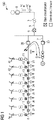
- Fig. 1 shows a wind farm which is controlled by a control device (not shown) in several operation modes, where a power generator G is supplying active power P to a first wind turbine A1 and balancing reactive power Q of passive cables and transformers therebetween, while the first wind turbine A1 is energized.
- Fig. 1 shows the wind farm in a first operation mode in a low wind condition, where a wind speed falls below a threshold value.
- the wind farm comprises a plurality of wind turbines A1, A2,..., An which are connected in parallel to each other in a first string A, which can be a string cable, wherein respective cable section circuit breakers 21, 22, ..., 27 are arranged between adjacent wind turbines of the first string A.
- Each wind turbine A, A2, ..., An in the first string A further comprises a corresponding wind turbine circuit breaker 11, 12, ..., 18 to connect or interrupt the respective wind turbine A, A2, ..., An to or from the first string A.
- the wind farm comprises a power generator G, for example a diesel generator or any other type of power source, which is connected to a first wind turbine A1 of the first string A, wherein, amongst others, a first string circuit breaker 20 is arranged in a line between the power generator G and the first wind turbine A1.
- the power generator G is connected to the first string A via a power generator circuit breaker 50.
- the wind farm is operated in various operation modes in the low wind condition, where the wind speed falls below the threshold value.
- the power generator circuit breaker 50 is closed in the low wind condition and can be opened in conditions other than the low wind condition.
- the first string circuit breaker 20 is closed to supply active power P from the power generator G to the first wind turbine A1 and to supply / consume reactive power Q from / to the power generator G to the cables and transformers between the power generator and the first wind turbine A1, while the remaining cable section circuit breakers 21, 22, ..., 27 in the first string A are opened.
- the power generator G energizes a first section, i.e., the first wind turbine A1 of the first string A, thereby supplying active to the first wind turbine A1 and balancing the reactive power of the cable and transformers between.
- Fig. 2 shows the wind farm in a second operation mode in the low wind condition after the first operation mode, where the power generator G is supplying active power P to the first and second wind turbines A1, A2, and the circuit breakers between the first and second wind turbines A1, A2 are closed.
- the first wind turbine A1 is balancing the reactive power Q of the cable and transformers, while the second wind turbine A2 is energized.
- a cable section circuit breaker 21 between the first wind turbine A1 and an adjacent second wind turbine A2 is closed to supply active power P from the power generator G to the first and second wind turbines A1, A2 and to supply reactive power Q from the first wind turbine A1 to the second wind turbine A2, while the remaining cable section circuit breakers 22, 23, ..., 27 in the first string A are opened.
- the wind farm comprises n wind turbines A1, A2, ..., An in the first string A, wherein the first wind turbine A1 is the most upstream wind turbine in the first string A and the n-th wind turbine An is the most downstream wind turbine in the first string A.
- the cable section circuit breakers 21, 22, ..., 27 are sequentially closed starting out from the cable section circuit breaker 21 between the first and second wind turbines A1, A2 up to a cable section circuit breaker 27 between the n-th wind turbine An and the n-1-th wind turbine An-1, thereby sequentially supplying active power P from the power generator G to the first to n-th wind turbines A1, A2, ..., An and sequentially supplying reactive power Q from or to the wind turbines to balance reactive power loads of the cables and transformers.
- Fig. 2 once the first wind turbine A1 is energized, the wind farm is then able to energize the second wind turbine A2 and the cables and transformer in between using its reactive power capability, while the power generator G supplies the active power load to both of them.
- the rest of the wind turbines in the first string A can now be energized sequentially one after the other along with the remainder of the first string A, if required.
- the reactive power Q of the first string A can be dominantly balanced by the wind turbines as soon as one or more of them is operating.
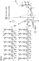
- Fig. 3 shows the wind farm in another operation mode after the second operation mode, where the circuit breakers between the n wind turbines of the first string A are closed and the power generator G is supplying active power P to the first string A of wind turbines, while the wind turbines balance the reactive power Q of the cables and transformers.
- the circuit breaker to the second string B and circuit breakers to the n wind turbines of the second string B are also closed, allowing the power generator G to supply active power P to the n wind turbines of the second string B and the n wind turbines of the first string A to balance the reactive power load of the second string cables and transformers, while the n wind turbines of the second string B are energized.
- the wind farm further comprises at least one further plurality of wind turbines B1, B2, ..., Bn which are connected in parallel to each other in at least one further string B, wherein respective cable section circuit breakers 41, 42, ..., 47 are arranged between adjacent wind turbines of the at least one further string B.
- the first wind turbine B1 is the most upstream wind turbine in the further string B and the n-th wind turbine Bn is the most downstream wind turbine in the further string B.
- Each wind turbine B, B2, ..., Bn in the at least one further string B further comprises a corresponding wind turbine circuit breaker 31, 32, ..., 38 to connect or interrupt the respective wind turbine B, B2, ..., Bn to or from the at least one other string B.
- the power generator G is also connected to a first wind turbine B1 of the at least one further string B, wherein at least one further string circuit breaker 40 is arranged in a line between the power generator G and the first wind turbine B1 of the at least one further string B.
- the first and second operation modes are performed in the at least one further string B in the same manner as in the first string A like in Figures 1 and 2 .
- the cable section circuit breakers 41, 42, ..., 47 in the at least one further string B are sequentially closed in the same manner as in the first string A like in Figures 1 and 2 .
- Reactive power Q is also supplied from the wind turbines of the first string A to the cables and transformers of the further string B.
- the further string circuit breaker 40 is closed to supply active power P from the power generator G to the first wind turbine B1 and to supply reactive power Q from or to the first string of wind turbines A to An to the cables and transformer between it and wind turbine B1, while the remaining cable section circuit breakers 41, 42, ..., 47 in the further string B are opened.
- the cable section circuit breaker 41 between the first wind turbine B1 and an adjacent second wind turbine B2 is closed to supply active power P from the power generator G to the first and second wind turbines B1, B2 and to supply reactive power Q from the first wind turbine B1 to the cables and transformers between it and wind turbine B2, while the remaining cable section circuit breakers 42, 43, ..., 47 in the further string B are opened.
- the cable section circuit breakers 41, 42, ..., 47 are sequentially closed starting out from the cable section circuit breaker 41 between the first and second wind turbines B1, B2 up to a cable section circuit breaker 47 between the n-th wind turbine Bn and the n-1-th wind turbine Bn-1, thereby sequentially supplying active power P from the power generator G to the first to n-th wind turbines B1, B2, ..., Bn and sequentially supplying / consuming reactive power Q to / from the wind turbines to a respective downstream cables and transformers.
- Fig. 4 shows the wind farm in another operation mode after the second operation mode or after the operation of Fig. 3 , where the circuit breakers between the power generator G, the n wind turbines of the first string A and the n wind turbines of the second string B are closed.
- the two strings A, B of wind turbines have been energized using active power P supplied by the power generator G and are collectively balancing the reactive power load of the cables and transformers.
- the wind farm further comprises a grid supply line 5 which is connected via a grid supply line circuit breaker 6 to a bus bar 7 between the first wind turbine A1 and the power generator G.
- the grid supply line circuit breaker 6 is closed, as shown in Fig. 4 , to supply active power P to and reactive power Q to / from the bus bar 7 between the first wind turbines A1, B1 and the power generator G to the grid supply line 5.
- the grid supply line 5 is connected to a grid 100 via a grid circuit breaker 8, wherein the grid supply line 5 comprises, between the grid supply line circuit breaker 6 and the grid circuit breaker 8, a grid transformer 9 and transmission lines 10, wherein the grid circuit breaker 8 is opened when performing the operation modes of the embodiments in Figures 1 to 3 , i.e., when a number smaller than minimum number of wind turbines in the first string A and/ or the at least one further string B are energized.
- Fig. 4 once a minimum number of wind turbines of the wind farm is energized, they are then capable of energizing power system components such as a grid transformer 9 and the transmission lines 10.
- Fig. 1 shows the energization of the first wind turbine A1 using the power generator G as an energy source.
- Fig. 2 shows how the combination of the first wind turbine A1 and the power generator G can energize the second, third, fourth and further wind turbines up to the minimum required number of wind turbines of the first string A to allow a further group in the further string B to be energized at once.
- Fig. 3 shows how the first group of wind turbines in the first string A energizes a second group of wind turbines in the further string B, which can be repeated until the whole wind farm is energized if required.
- Fig. 4 shows how a group of wind turbines, of minimum size, can energize other power system components.
- the wind farm can self-energize and maintain the energization of itself and parts of the transmission system when the wind speed is too low for power production by the wind turbines themselves.
- the size of the power generator G or an additional energy source, which is required to energize/maintain the energization of the wind farm in the low wind condition, can be relatively small in comparison to the rated power of the wind farm.
- This capability would bring further advantages, as it would allow to perform a black start of the grid regardless of the wind speed. It would also remove the need for a wind farm operator to install temporary large diesel generators and reactive compensation equipment, if a prolonged grid outage is expected, to maintain the wind farm climatic control.
- the present invention also avoids the provision of a standalone diesel generator or energy storage device which must be sized to provide the same reactive power capability of all of the wind turbine power converters as well as the active power loads. Such a large diesel generator or storage device would dramatically increase the cost.
Landscapes
- Engineering & Computer Science (AREA)
- Power Engineering (AREA)
- Control Of Eletrric Generators (AREA)
- Wind Motors (AREA)
Priority Applications (4)
| Application Number | Priority Date | Filing Date | Title |
|---|---|---|---|
| EP21170870.6A EP4084260A1 (fr) | 2021-04-28 | 2021-04-28 | Procédé pour fournir de l'énergie à un parc éolien en condition de vent faible |
| EP22718094.0A EP4305724A1 (fr) | 2021-04-28 | 2022-03-22 | Procédé d'alimentation en énergie de parc éolien dans des conditions de vent faible |
| CN202280032001.7A CN117242666A (zh) | 2021-04-28 | 2022-03-22 | 在低风条件下向风电场供应电力的方法 |
| PCT/EP2022/057491 WO2022228784A1 (fr) | 2021-04-28 | 2022-03-22 | Procédé d'alimentation en énergie de parc éolien dans des conditions de vent faible |
Applications Claiming Priority (1)
| Application Number | Priority Date | Filing Date | Title |
|---|---|---|---|
| EP21170870.6A EP4084260A1 (fr) | 2021-04-28 | 2021-04-28 | Procédé pour fournir de l'énergie à un parc éolien en condition de vent faible |
Publications (1)
| Publication Number | Publication Date |
|---|---|
| EP4084260A1 true EP4084260A1 (fr) | 2022-11-02 |
Family
ID=75728672
Family Applications (2)
| Application Number | Title | Priority Date | Filing Date |
|---|---|---|---|
| EP21170870.6A Withdrawn EP4084260A1 (fr) | 2021-04-28 | 2021-04-28 | Procédé pour fournir de l'énergie à un parc éolien en condition de vent faible |
| EP22718094.0A Pending EP4305724A1 (fr) | 2021-04-28 | 2022-03-22 | Procédé d'alimentation en énergie de parc éolien dans des conditions de vent faible |
Family Applications After (1)
| Application Number | Title | Priority Date | Filing Date |
|---|---|---|---|
| EP22718094.0A Pending EP4305724A1 (fr) | 2021-04-28 | 2022-03-22 | Procédé d'alimentation en énergie de parc éolien dans des conditions de vent faible |
Country Status (3)
| Country | Link |
|---|---|
| EP (2) | EP4084260A1 (fr) |
| CN (1) | CN117242666A (fr) |
| WO (1) | WO2022228784A1 (fr) |
Citations (4)
| Publication number | Priority date | Publication date | Assignee | Title |
|---|---|---|---|---|
| EP3204636A1 (fr) * | 2014-10-10 | 2017-08-16 | ABB Schweiz AG | Procédé et système de protection de parc éolien lors d'une déconnexion vis-à-vis d'un réseau électrique |
| EP3533996A1 (fr) * | 2018-02-28 | 2019-09-04 | Siemens Gamesa Renewable Energy A/S | Procédé de démarrage d'un parc éolien |
| EP3641090A1 (fr) * | 2018-10-18 | 2020-04-22 | General Electric Company | Systèmes et procédés de gestion dynamique d'éoliennes fournissant une puissance réactive |
| US20210047997A1 (en) * | 2018-01-25 | 2021-02-18 | Mhi Vestas Offshore Wind A/S | Black start restoration |
-
2021
- 2021-04-28 EP EP21170870.6A patent/EP4084260A1/fr not_active Withdrawn
-
2022
- 2022-03-22 EP EP22718094.0A patent/EP4305724A1/fr active Pending
- 2022-03-22 CN CN202280032001.7A patent/CN117242666A/zh active Pending
- 2022-03-22 WO PCT/EP2022/057491 patent/WO2022228784A1/fr active Application Filing
Patent Citations (4)
| Publication number | Priority date | Publication date | Assignee | Title |
|---|---|---|---|---|
| EP3204636A1 (fr) * | 2014-10-10 | 2017-08-16 | ABB Schweiz AG | Procédé et système de protection de parc éolien lors d'une déconnexion vis-à-vis d'un réseau électrique |
| US20210047997A1 (en) * | 2018-01-25 | 2021-02-18 | Mhi Vestas Offshore Wind A/S | Black start restoration |
| EP3533996A1 (fr) * | 2018-02-28 | 2019-09-04 | Siemens Gamesa Renewable Energy A/S | Procédé de démarrage d'un parc éolien |
| EP3641090A1 (fr) * | 2018-10-18 | 2020-04-22 | General Electric Company | Systèmes et procédés de gestion dynamique d'éoliennes fournissant une puissance réactive |
Also Published As
| Publication number | Publication date |
|---|---|
| CN117242666A (zh) | 2023-12-15 |
| WO2022228784A1 (fr) | 2022-11-03 |
| EP4305724A1 (fr) | 2024-01-17 |
Similar Documents
| Publication | Publication Date | Title |
|---|---|---|
| US11462914B2 (en) | Method for black-starting an electrical grid | |
| US8000840B2 (en) | Method of start up at least a part of a wind power plant, wind power plant and use of the wind power plant | |
| Feltes et al. | Black start studies for system restoration | |
| US6404075B1 (en) | Uninterruptible power generation system | |
| US7447568B2 (en) | Electric power network | |
| US20070129110A1 (en) | Interface switch for distributed energy resources | |
| US20220209540A1 (en) | A method for black-starting an electrical grid | |
| JP2009153333A (ja) | 分散型電源システム及びその制御方法 | |
| Ilyushin et al. | The effect of complex load on the reliable operation of solar photovoltaic and wind power stations integrated into energy systems and into off-grid energy areas | |
| EP4084260A1 (fr) | Procédé pour fournir de l'énergie à un parc éolien en condition de vent faible | |
| WO2020131005A1 (fr) | Sous-système de commande de courant de défaut et procédé associé | |
| Dumitrescu | Design Study Case Overview for Naval Power Generation and Delivery | |
| Verma et al. | Restoration of extra-high voltage power grids through synchronous and asynchronous hydro units during blackout—A comprehensive review and case study | |
| Firmin et al. | Analysis of reducing electrical losses in parallel transmission/distribution transformers | |
| Gilany et al. | Reducing the short circuit levels in Kuwait transmission network (A case study) | |
| Kundu | An overview of the distributed generation (DG) connected to the grid | |
| Han et al. | Commissioning and Testing of the KangJin UPFC in Korea | |
| Turner et al. | A new UPS topology for multi-megawatt medium voltage power protection | |
| Ilyushin et al. | How Distributed Energy Sources Affect Technical Requirements to Relay Protection and Automation | |
| Hamilton | Starting of large hv motors on a weak power system-a case study | |
| Daley | Design considerations for operating on-site generators in parallel with utility service | |
| WO2024052083A1 (fr) | Système de distribution d'énergie pour centre de données | |
| Nallagownden et al. | Power system studies for reliable operation of an offshore platform | |
| Blažič et al. | Large-scale integration of distributed energy resources in power networks | |
| Lescale et al. | ABB HVDC ABB HVDC ABB HVDC |
Legal Events
| Date | Code | Title | Description |
|---|---|---|---|
| PUAI | Public reference made under article 153(3) epc to a published international application that has entered the european phase |
Free format text: ORIGINAL CODE: 0009012 |
|
| STAA | Information on the status of an ep patent application or granted ep patent |
Free format text: STATUS: THE APPLICATION HAS BEEN PUBLISHED |
|
| AK | Designated contracting states |
Kind code of ref document: A1 Designated state(s): AL AT BE BG CH CY CZ DE DK EE ES FI FR GB GR HR HU IE IS IT LI LT LU LV MC MK MT NL NO PL PT RO RS SE SI SK SM TR |
|
| STAA | Information on the status of an ep patent application or granted ep patent |
Free format text: STATUS: THE APPLICATION IS DEEMED TO BE WITHDRAWN |
|
| 18D | Application deemed to be withdrawn |
Effective date: 20230503 |