EP4083772A1 - Control device and control program - Google Patents
Control device and control program Download PDFInfo
- Publication number
- EP4083772A1 EP4083772A1 EP20907362.6A EP20907362A EP4083772A1 EP 4083772 A1 EP4083772 A1 EP 4083772A1 EP 20907362 A EP20907362 A EP 20907362A EP 4083772 A1 EP4083772 A1 EP 4083772A1
- Authority
- EP
- European Patent Office
- Prior art keywords
- task
- list
- priority list
- control unit
- item
- Prior art date
- Legal status (The legal status is an assumption and is not a legal conclusion. Google has not performed a legal analysis and makes no representation as to the accuracy of the status listed.)
- Pending
Links
Images







Classifications
-
- H—ELECTRICITY
- H04—ELECTRIC COMMUNICATION TECHNIQUE
- H04N—PICTORIAL COMMUNICATION, e.g. TELEVISION
- H04N1/00—Scanning, transmission or reproduction of documents or the like, e.g. facsimile transmission; Details thereof
- H04N1/0035—User-machine interface; Control console
- H04N1/00501—Tailoring a user interface [UI] to specific requirements
- H04N1/00506—Customising to the data to be displayed
-
- G—PHYSICS
- G06—COMPUTING OR CALCULATING; COUNTING
- G06F—ELECTRIC DIGITAL DATA PROCESSING
- G06F3/00—Input arrangements for transferring data to be processed into a form capable of being handled by the computer; Output arrangements for transferring data from processing unit to output unit, e.g. interface arrangements
- G06F3/01—Input arrangements or combined input and output arrangements for interaction between user and computer
- G06F3/048—Interaction techniques based on graphical user interfaces [GUI]
- G06F3/0481—Interaction techniques based on graphical user interfaces [GUI] based on specific properties of the displayed interaction object or a metaphor-based environment, e.g. interaction with desktop elements like windows or icons, or assisted by a cursor's changing behaviour or appearance
- G06F3/0482—Interaction with lists of selectable items, e.g. menus
-
- G—PHYSICS
- G06—COMPUTING OR CALCULATING; COUNTING
- G06F—ELECTRIC DIGITAL DATA PROCESSING
- G06F3/00—Input arrangements for transferring data to be processed into a form capable of being handled by the computer; Output arrangements for transferring data from processing unit to output unit, e.g. interface arrangements
- G06F3/01—Input arrangements or combined input and output arrangements for interaction between user and computer
- G06F3/048—Interaction techniques based on graphical user interfaces [GUI]
- G06F3/0484—Interaction techniques based on graphical user interfaces [GUI] for the control of specific functions or operations, e.g. selecting or manipulating an object, an image or a displayed text element, setting a parameter value or selecting a range
- G06F3/0485—Scrolling or panning
-
- G—PHYSICS
- G06—COMPUTING OR CALCULATING; COUNTING
- G06F—ELECTRIC DIGITAL DATA PROCESSING
- G06F3/00—Input arrangements for transferring data to be processed into a form capable of being handled by the computer; Output arrangements for transferring data from processing unit to output unit, e.g. interface arrangements
- G06F3/01—Input arrangements or combined input and output arrangements for interaction between user and computer
- G06F3/048—Interaction techniques based on graphical user interfaces [GUI]
- G06F3/0487—Interaction techniques based on graphical user interfaces [GUI] using specific features provided by the input device, e.g. functions controlled by the rotation of a mouse with dual sensing arrangements, or of the nature of the input device, e.g. tap gestures based on pressure sensed by a digitiser
- G06F3/0488—Interaction techniques based on graphical user interfaces [GUI] using specific features provided by the input device, e.g. functions controlled by the rotation of a mouse with dual sensing arrangements, or of the nature of the input device, e.g. tap gestures based on pressure sensed by a digitiser using a touch-screen or digitiser, e.g. input of commands through traced gestures
- G06F3/04883—Interaction techniques based on graphical user interfaces [GUI] using specific features provided by the input device, e.g. functions controlled by the rotation of a mouse with dual sensing arrangements, or of the nature of the input device, e.g. tap gestures based on pressure sensed by a digitiser using a touch-screen or digitiser, e.g. input of commands through traced gestures for inputting data by handwriting, e.g. gesture or text
-
- H—ELECTRICITY
- H04—ELECTRIC COMMUNICATION TECHNIQUE
- H04N—PICTORIAL COMMUNICATION, e.g. TELEVISION
- H04N1/00—Scanning, transmission or reproduction of documents or the like, e.g. facsimile transmission; Details thereof
- H04N1/0035—User-machine interface; Control console
- H04N1/00405—Output means
- H04N1/00408—Display of information to the user, e.g. menus
- H04N1/00413—Display of information to the user, e.g. menus using menus, i.e. presenting the user with a plurality of selectable options
- H04N1/00416—Multi-level menus
- H04N1/00419—Arrangements for navigating between pages or parts of the menu
- H04N1/00427—Arrangements for navigating between pages or parts of the menu using a menu list
-
- H—ELECTRICITY
- H04—ELECTRIC COMMUNICATION TECHNIQUE
- H04N—PICTORIAL COMMUNICATION, e.g. TELEVISION
- H04N1/00—Scanning, transmission or reproduction of documents or the like, e.g. facsimile transmission; Details thereof
- H04N1/0035—User-machine interface; Control console
- H04N1/00405—Output means
- H04N1/00474—Output means outputting a plurality of functional options, e.g. scan, copy or print
-
- H—ELECTRICITY
- H04—ELECTRIC COMMUNICATION TECHNIQUE
- H04N—PICTORIAL COMMUNICATION, e.g. TELEVISION
- H04N1/00—Scanning, transmission or reproduction of documents or the like, e.g. facsimile transmission; Details thereof
- H04N1/0035—User-machine interface; Control console
- H04N1/00501—Tailoring a user interface [UI] to specific requirements
- H04N1/00509—Personalising for a particular user or group of users, e.g. a workgroup or company
- H04N1/00517—Personalising for a particular user or group of users, e.g. a workgroup or company involving favourite or frequently used settings
Definitions
- the technology of the present disclosure relates to a control device and a control program.
- a so-called multi-function peripheral that executes a plurality of functions such as a copy function, a scanning function, a facsimile function, and a printing function is known.
- a technology in which tasks used in the past are displayed as a history list has been widely used in order to enable easy and quick selection of a function to be executed by such an information apparatus such as a multi-function peripheral.
- JP-A Japanese Patent Application Laid-Open ( JP-A) No. 2006-185351 describes that display means that displays a list of menu items recorded in history information and execution means that executes, in a case where a menu item displayed in the list by the display means is selected, processing associated with the selected menu item are included, and a fixed menu item and a history menu item that are frequently executed are displayed on the same screen.
- the fixed menu item and the history menu item are displayed in separate regions, respectively, and it is necessary to separately scroll through the fixed menu items and the history menu items when selecting a menu item. Therefore, it is necessary to select which menu items to scroll through.
- An object of the technology of the disclosure is to provide a control device and a control program capable of eliminating the need to select which of a priority list and a history list to scroll through.
- a first aspect is a control device including a display control unit that controls display of a task selection screen which is a task selection screen for selecting one task item from a plurality of task items and in which a priority list, which is a list of preset task items, and a history list, which includes histories of task items executed in the past, are displayed in parallel, in which the display control unit is configured to integrally scroll through the priority list and the history list.
- a second aspect is the control apparatus according to the first aspect, in which the one task item is a task item for any of a copy function, a scanning function, a printing function or a facsimile function.
- a third aspect is the control device according to the first or second aspect, in which the plurality of task items include task items for different functions, and the task item is displayed in a color different for each function at the task selection screen.
- a fourth aspect is the control device according to any one of the first to third aspects, in which a setting button is arranged at the task item in the priority list, and the display control unit is configured to perform one or more of rearrangement of the task items in the priority list, deletion of the task item from the priority list or name change of the task item, based on an operation of the setting button.
- a fifth aspect is the control device according to any one of the first to fourth aspects, in which the task item in the priority list is initially settable.
- a sixth aspect is the control device according to any one of the first to third aspects, in which a setting button is arranged at the task item in the history list, and the display control unit is configured to perform one or more of movement to the priority list or deletion from the priority list, based on an operation of the setting button.
- a seventh aspect is the control device according to the third aspect, in which in a case in which a desired task item is selected, transition is made to a task execution screen for the selected task item, and the task execution screen is displayed in the same color as a color in which the task item is displayed.
- An eighth aspect is a control program for causing a computer to function as a control device, the control device including a display control unit that controls display of a task selection screen which is a task selection screen for selecting one task item from a plurality of task items and in which a priority list, which is a list of preset task items, and a history list, which includes histories of task items executed in the past, are displayed in parallel, in which the display control unit is configured to integrally scroll through the priority list and the history list.
- Fig. 1 is a view illustrating an appearance of the multi-function peripheral 100 according to the present embodiment.
- Fig. 2 is a block diagram illustrating a hardware configuration of the multi-function peripheral 100.
- the multi-function peripheral 100 illustrated in Figs. 1 and 2 is a device capable of executing processing for functions such as copying, printing, scanning, and facsimile. As illustrated in Fig. 2 , the multi-function peripheral 100 includes a control device 110, a reading unit 102, an image forming unit 103, and a communication unit 104 in a main body 150. Note that the multi-function peripheral 100 is an example of the information apparatus.
- the multi-function peripheral 100 can perform data communication with an information processing apparatus such as a personal computer or a server in an office connected to a local area network (LAN) line or the like or perform facsimile communication with a communication apparatus in another office through a public line such as a telephone line. Therefore, the multi-function peripheral 100 is also an example of the information communication apparatus.
- LAN local area network
- An operation panel 120, the control device 110 including a storage device 113, the reading unit 102, the image forming unit 103, and the communication unit 104 are mutually connected by a bus 109.
- Each unit of the multi-function peripheral 100 will be described below.
- the reading unit 102 reads an image of a document. Specifically, the reading unit 102 generates image data by optically reading an image of a document and converting the image into a digital signal.
- the image forming unit 103 forms an image on a medium such as a paper sheet. Specifically, the image forming unit 103 forms an image on a medium by, for example, an electrophotographic method in which an image is formed by electrostatically attaching a toner onto a paper sheet. Note that the image forming unit 103 may form an image on a medium by another method such as an inkjet method in which an image is formed by ejecting an ink onto a paper sheet.
- the communication unit 104 communicates with an external device such as another facsimile device. Specifically, the communication unit 104 transmits and receives various pieces of data to and from an external device by communication using various wired or wireless communication lines. Examples of the communication line include the Internet, an intranet, and a public telephone line.
- the multi-function peripheral 100 includes a document feeding device 151 provided at an upper portion of the main body 150 as illustrated in Fig. 1 .
- the document feeding device 151 feeds a document to a document reading stage (not illustrated) disposed on an upper surface of the main body 150.
- the reading unit 102 is disposed at a position facing the reading stage in the main body 150.
- the document feeding device 151 can be lifted up. As the document feeding device 151 is lifted up, the reading stage is exposed and can be used as a so-called flatbed type. Therefore, a user can directly set a document on the reading stage without using the document feeding device 151.
- An image of a document is read by the reading unit 102, and image data is generated.
- the image forming unit 103 prints an image of a document on another paper sheet based on image data generated by the reading unit 102.
- the paper sheet on which an image is printed is discharged to a paper sheet discharging unit 152 provided in the main body 150.
- image data generated by the reading unit 102 is output to the communication unit 104 and transmitted to a destination via the communication unit 104.
- the image forming unit 103 prints an image on a paper sheet based on image data input from a personal computer or the like.
- the paper sheet on which an image is printed is discharged to the paper sheet discharging unit 152.
- a feeding unit in which a paper sheet is loaded, a paper sheet transport mechanism that transports a paper sheet to the image forming unit 103 and the paper sheet discharging unit 152, and the like are provided inside the main body 150.
- the multi-function peripheral 100 includes the operation panel 120 for a user to operate the multi-function peripheral 100.
- the operation panel 120 is an example of a user interface.
- the user interface is a device for exchanging information between the multi-function peripheral 100 and a user, specifically, for inputting an operation instruction from a user to the multi-function peripheral 100 or displaying information such as a status of the multi-function peripheral 100 to a user.
- the operation panel 120 includes a display unit 121 and an operation unit 122 as illustrated in Figs. 2 and 3 .
- the display unit 121 displays an operation screen, various messages such as operation guidance, and the like.
- the operation unit 122 is a component on which a user performs an input operation.
- the display unit 121 is implemented by, for example, a liquid crystal display, an organic electro luminescence (EL) display, or the like.
- the operation unit 122 and the display unit 121 are implemented by a touch panel display 123 in which both the operation unit 122 and the display unit 121 are integrated.
- the operation unit 122 is a resistive type touch panel, a capacitive type touch panel, or the like, and detects a touch operation of a user.
- the operation unit 122 detects the touch operation performed on the operation screen and a position at which the touch operation is performed on the operation screen, and outputs a detection signal to the control device 110.
- Examples of the touch operation of the user include operations such as tapping, flicking, sliding, and dragging.
- the tapping operation is an operation of touching the screen of the display unit 121 with a finger.
- the flicking operation is an operation of touching the screen of the display unit 121 in such a way as to flick the screen with a finger.
- the sliding operation is an operation of moving a finger in a state of touching the screen of the display unit 121 with the finger.
- the dragging operation is an operation for moving an image such as an icon displayed on the display unit 121.
- the dragging operation is an operation of touching an image displayed on the display unit 121 with a finger, then moving the finger touching the image, and then releasing the finger from the image.
- the operation unit 122 that is a touch panel outputs, as a detection signal, a movement locus of a finger associated with these touch operations in an operation screen.
- the touch operation may be not only an operation using a finger of a user but also an operation using a tool such as a touch pen.
- the operation panel 120 further includes an operation key 124 disposed outside the screen of the display unit 121 as illustrated in Fig. 1 .
- Examples of the operation key 124 include a power key for supplying power to the multi-function peripheral 100, a cancel key for canceling various executions, and the like.
- the operation panel 120 according to the present embodiment includes a mechanical operation unit in addition to the touch panel display 123 including the operation unit 122.
- the display unit 121 can display various operation screens such as a task selection screen 300 illustrated in Fig. 4 and a task execution screen 350 illustrated in Fig. 5 , for example. Details of the task selection screen 300 and the task execution screen 350 will be described later.
- the control device 110 is a device that controls each unit of the multi-function peripheral 100 including the operation panel 120.
- the control device 110 includes a central processing unit (CPU) 111, a memory 112, and a storage device 113 as illustrated in Fig. 2 .
- the control device 110 controls the multi-function peripheral 100 based on information stored in the storage device 113.
- the storage device 113 stores various programs including a control program 130 and various pieces of data including function control data 131 and user interface (UI) control data 132.
- the control program 130 is a program that causes a computer including the CPU 111 to function as the control device 110.
- the function control data 131 is data used to control the reading unit 102, the image forming unit 103, and the communication unit 104, and includes various pieces of setting information, processing parameters, and the like.
- the processing parameter is, for example, a parameter used when image correction processing such as gain correction, contrast correction, white balance correction, or gamma correction is executed.
- the various pieces of setting information include setting information that specifies processing conditions for each of the copy function, the scanning function, the printing function, and the like implemented by the reading unit 102, the image forming unit 103, and the communication unit 104.
- the setting information is setting information that specifies processing conditions such as paper sheet size setting and color setting (for example, black-and-white copy or color copy)
- the setting information is setting information that specifies processing conditions such as reading resolution setting and color setting (for example, black-and-white reading or color reading).
- the setting information includes user setting information set by a user in addition to initial setting information.
- the various pieces of setting information also include a history of user setting information used by a user in the past.
- the UI control data 132 includes various pieces of screen data for configuring an operation screen displayed by the display unit 121 and various pieces of table data defining various setting items and the like displayed in an operation screen.
- the storage device 113 is implemented by a recording device such as a hard disk drive (HDD), a solid state drive (SSD), or a flash memory.
- the memory 112 is a work area for the CPU 111 to execute various programs, and temporarily records various programs or various pieces of data when the CPU 111 executes processing.
- the CPU 111 reads various programs including the control program 130 from the storage device 113 to the memory 112, and executes the program by using the memory 112 as a work area.
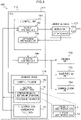
- Fig. 3 is a block diagram illustrating a functional configuration of the CPU 111, and is a block diagram mainly illustrating a functional configuration that implements control of the operation panel 120.
- the CPU 111 functions as a UI control unit 141 and a function control unit 144 by executing the control program 130.
- the function control unit 144 controls the reading unit 102, the image forming unit 103, and the communication unit 104 while referring to the function control data based on an operation instruction input from the UI control unit 141.
- the function control unit 144 outputs, to the UI control unit 141, a processing execution result in the reading unit 102, the image forming unit 103, and the communication unit 104, a status, and the like.
- the UI control unit 141 receives an operation instruction input from the operation panel 120 and outputs the received operation instruction to the function control unit 144.
- the UI control unit 141 controls the touch panel display 123.
- the UI control unit 141 includes a display control unit 142 and an operation receiving unit 143 as the functional configuration.
- the operation receiving unit 143 receives an operation instruction according to a user's operation input from the operation panel 120, the user's operation input including a user's touch operation detected by the operation unit 122 of the touch panel display 123.
- the display control unit 142 performs control to display various operation screens on the display unit 121 of the touch panel display 123 with reference to the function control data 131 and the UI control data 132.
- the display control unit 142 causes the display unit 121 to display the task selection screen 300 (see Fig. 4 ) as a top screen, as an example.
- the task selection screen 300 is a screen for a user to select and operate a task item 301 (see Fig. 4 ) to be executed by the multi-function peripheral 100.
- a task is processing executed by the multi-function peripheral 100 after a user sets a processing condition for a main function of the multi-function peripheral 100. Then, an item including information indicating the content of this processing is referred to as the task item 301.
- processing executed by the multi-function peripheral 100 after a user sets the processing conditions such as paper sheet size setting and color setting is the task of the copy function, and an item indicating the content of the task is the task item 301.
- processing executed by the multi-function peripheral 100 after a user sets the processing conditions such as reading resolution setting and color setting is the task of the scanning function, and an item indicating the content of the task is the task item 301.
- the task selection screen 300 is a selection screen for selecting one task item 301 from the plurality of task items 301 in the case of causing the multi-function peripheral 100 to execute one task.
- Various pieces of setting information of the function control data 131 include priority list information 11 and history list information 12.
- the storage device 113 is a priority list recording unit in which the priority list information 11 is recorded and a history list recording unit in which the history list information 12 is recorded.
- the priority list information 11 is information in which a plurality of preset task items 301 are recorded.
- the task items 301 included in the priority list information 11 include, for example, task items that are preset due to a high execution frequency.
- the task items 301 included in the priority list information 11 may be initially set at the time of product shipment or may be set by a user.
- the history list information 12 is information in which histories of the task items 301 executed in the past by the multi-function peripheral 100 are recorded.
- the name of each task item 301, an arrangement order, and the like are recorded in the priority list information 11.
- the name of each task item 301, an execution date and time when each task item 301 was executed, and the like are recorded in the history list information 12.
- the display control unit 142 generates the task selection screen 300 including a priority list 1 and a history list 2 with reference to the priority list information 11 and the history list information 12. Specifically, when generating the priority list 1, the display control unit 142 generates the priority list 1 by arranging the task items 301 of the priority list 1 in order based on the name and the arrangement order of each task item 301 included in the priority list information 11. When generating the history list 2, the display control unit 142 generates the history list 2 by arranging the task items 301 of the history list 2 in order based on the name and the execution date and time of each task item 301 included in the history list information 12. The display control unit 142 displays the priority list 1 and the history list 2 in parallel in the task selection screen 300.
- the display control unit 142 displays the priority list 1 that is a list of preset task items 301, and the history list 2 that includes histories of task items 301 executed in the past in the multi-function peripheral 100, in parallel in the task selection screen 300.
- the priority list 1 is displayed above the history list 2 in the task selection screen 300.
- the task items 301 of the history list 2 are displayed in time series based on the execution date and time of each task item 301 recorded in the history list information 12. Specifically, as an example, the task items 301 are displayed in a direction along an arrow X2 in order from a task item 301 with the latest execution date and time. Therefore, the most recently executed task item 301 is displayed at the uppermost portion of the history list 2 (that is, a position closest to an X1 direction side).
- each of the plurality of task items 301 included in the priority list 1 or the history list 2 is a task item for any of the four main functions of the multi-function peripheral 100, that is, the copy function, the scanning function, the printing function, and the facsimile function.
- the task item 301 registered in the priority list 1 or the history list 2 corresponds to any of the four main functions of the multi-function peripheral 100.
- supplementary functions of the multi-function peripheral 100 other than the main four functions are excluded from the functions registered in the priority list 1 or the history list 2.
- At least one of the plurality of task items 301 registered in the priority list 1 or the history list 2 preferably includes a task item 301 for the copy function considered to have a relatively high execution frequency among the four main functions.
- the task item 301 of the priority list 1 can be customized by a user. Specifically, rearrangement of the task items 301 in the priority list 1, name change, and addition of a task item 301 from the history list 2 can be made as will be described later.
- the function control unit 144 adds data of an executed task item 301 to the history list information 12 every time a task item 301 is executed by the multi-function peripheral 100. In a case where the history list information 12 is updated, the display control unit 142 updates the history list 2 in the task selection screen 300.
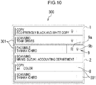
- a setting button 8 for displaying a registration menu 9 (see Fig. 10 ) is displayed on the right side of a task item 301 of the history list 2 in the task selection screen 300.
- a pinning mark 5 indicating that it is a task item 301 of the priority list 1 and a setting button 6 for displaying a registration menu 7 (see Fig. 7 ) are displayed on the right side of a task item 301 of the priority list 1.
- the pinning mark 5 indicates it is a task item 301 whose display is not updated even when another task item is executed.
- Fig. 4 for example, "black-and-white copy” 1a, "color copy” 2a, “facsimile” 2b, “scanning” 2c, and the like are displayed as the task items 301 in the task selection screen 300 according to the present embodiment. A user name is also displayed in the task items 301, "fax" 2b and “scanning” 2c. "Black-and-white copy” 1a having a high execution frequency is displayed in the priority list 1.
- a color display portion 3 colored in a specific color is arranged on the left side of each task item 301.
- the color display portions 3 arranged in "black-and-white copy" 1a and "color copy” 2a, which are the same copy functions, are displayed in the same color.
- the plurality of task items 301 include task items for a plurality of functions selected from the four main functions of the multi-function peripheral 100, that is, the copy function, the fax function, the scanning function, and the printing function, and the task item 301 is displayed in a different color for each function in the task selection screen 300.
- a plurality of task items 301 corresponding to the same function are bundled as the same type of task items 301, and the same color is assigned.
- Task items 301 to be bundled as the same type of task items 301 are set in advance. For example, information regarding which task items 301 are set as the same type of task items 301 and which color is assigned to the task items is recorded in the table data of the UI control data 132.
- the display control unit 142 displays the color display portion 3 with reference to the data. By doing so, the color of the color display portion 3 is determined, and the color display portion 3 is displayed.
- "fax" 2b and "scan" 2c which are the task items 301 with the same "user" may be set as the same type of task items 301, and the same color may be assigned to these task items 301.
- the color of the color display portion 3 may be changed by a setting change operation performed by a user.
- the priority list 1 and the history list 2 are displayed in the same task selection screen 300.
- the task selection screen 300 may display a list for each user as the priority list 1 and the history list 2.
- the display unit 121 displays the priority list 1 and the history list 2 of the authenticated user in the task selection screen.
- the priority list information 11 is information corresponding to the priority list 1 associated with each user, and a task item 301 included in the priority list information 11 for each user can be set for each user.
- the history list information 12 is information corresponding to the history list 2 associated with each user, and a task item 301 included in the history list information 12 for each user is updated based on the history for each user.
- the operation receiving unit 143 receives an operation instruction for the scrolling operation.
- This operation instruction is input to the display control unit 142.
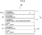
- the display control unit 142 integrally scrolls through the priority list 1 and the history list 2 as illustrated in Fig. 6 based on the input operation instruction for the scrolling operation.
- the scrolling operation is a flicking operation in a direction along an arrow X1 or a direction along an arrow X2 (see Fig. 4 ).
- the display control unit 142 integrally handles the priority list 1 and the history list 2 as an integrated list. In other words, at the time of scrolling, the priority list 1 and the history list 2 are scrolled as one integrated list without being distinguished from each other.
- the scrolling operation can be performed only in the X1 direction in which the number of displayed task items 301 of the priority list 1 decreases in the state illustrated in Fig. 4 in the task selection screen 300. Therefore, only a flicking operation in the X1 direction is valid in the state illustrated in Fig. 4 in the task selection screen 300.
- the priority list 1 and the history list 2 can also be scrolled in the X2 direction after being scrolled in the X1 direction.
- the scrolling operation for the priority list 1 and the history list 2 is performed by moving the priority list 1 and the history list 2 in the X1 direction or the X2 direction for which the flicking operation has been performed.
- task items 301 that have not been displayed are sequentially displayed in the task selection screen 300.
- Fig. 6 illustrates a state in which the priority list 1 and the history list 2 have been moved by one task item 301 in the direction along the arrow X1 in the state illustrated in Fig. 4 .
- the priority list 1 and the history list 2 can be scrolled integrally in the scrolling of the task selection screen 300.
- the setting button 6 is arranged in a task item 301 in the priority list 1.
- the display control unit 142 can execute one or more of deletion of a task item 301 from the priority list 1 and name change of a task item 301 based on the operation of the setting button 6.
- the operation receiving unit 143 receives an operation instruction for the operation of the setting button 6.
- the display control unit 142 displays the registration menu 7 as illustrated in Fig. 7 based on the operation instruction received by the operation receiving unit 143.
- a rearrangement button 7a, a delete button 7b, and a name change button 7c of a task item 301 are arranged in the registration menu 7.
- the operation receiving unit 143 receives an operation instruction for the operation of the rearrangement button 7a.
- the display control unit 142 shifts the task selection screen 300 displayed on the display unit 121 to a rearrangement mode based on the operation instruction received by the operation receiving unit 143.
- a moving operation (specifically, a dragging operation) for a task item 301 in the priority list 1 is enabled as indicated by an arrow A in Fig. 8 .
- the operation receiving unit 143 receives an operation instruction for the moving operation.
- the display control unit 142 changes the arrangement order of the task items 301 by moving a task item 301 in the priority list 1 based on the operation instruction received by the operation receiving unit 143.
- the display control unit 142 rewrites the arrangement order of the task items 301 recorded in the priority list information 11, and displays the priority list 1 in the rewritten arrangement order.
- the display control unit 142 may cancel the rearrangement mode and display the original task selection screen 300 after a predetermined time elapses.
- a rearrangement button 7al (see Fig. 9 ) having a movement instruction function of moving a task item 301 to the uppermost portion of the priority list 1 may be used as the rearrangement button 7a.
- the display control unit 142 moves a task item 301 for which the rearrangement button 7al has been operated to the uppermost portion of the priority list 1 and displays the priority list 1.
- the operation is simplified.
- the display control unit 142 deletes a task item 301 of the priority list 1. That is, once the operation unit 122 detects an operation for the delete button 7b, one task item 301 instructed to be deleted is deleted from the priority list information 11, and the display control unit 142 displays the priority list 1 based on the priority list information 11 after the deletion.
- the display control unit 142 displays the priority list 1 and the history list 2 from which a place generated due to the deletion is removed. That is, the display control unit 142 increases the number of task items 301 in the history list 2 by the number of task items 301 deleted from the priority list 1, and displays a new priority list 1 and history list 2 whose numbers of task items 301 have been changed.
- the display control unit 142 shifts the task selection screen 300 to a name input screen (not illustrated).
- a new changed name can be input.
- a keyboard screen is displayed as a name input screen, and a new name can be input through the keyboard.
- the keyboard screen is provided with, for example, a confirm button and a cancel button.
- the display control unit 142 changes the name of the task item 301 of the priority list 1. That is, once the operation unit 122 detects the confirmation operation after a new name is input, the display control unit 142 changes the name of a task item 301 recorded in the priority list information 11, and the display control unit 142 displays the task item 301 based on data of the changed name of the task item 301.
- a confirmation operation specifically, a flicking operation or a tapping operation for the confirm button
- a task item 301 in the priority list 1 may be initially set at the time of product shipment. In this case, for example, the task item 301 having a high execution frequency is generally set.
- the initial setting information is recorded in the priority list information 11 as described above.
- the setting button 8 is arranged in a task item 301 in the history list 2.
- the operation unit 122 detects an operation (specifically, a flicking operation or a tapping operation) for the setting button 8 of the history list 2
- the display control unit 142 displays the registration menu 9 as illustrated in Fig. 10 .
- a delete button 9a and a movement button 9b are arranged in the registration menu 9.
- the display control unit 142 deletes a task item 301 of the history list 2. That is, once the operation unit 122 detects an operation for the delete button 9a, one task item 301 instructed to be deleted is deleted from the history list information 12, and the display control unit 142 displays the history list 2 based on the history list information 12 after the deletion.
- the display control unit 142 displays the history list 2 from which a place generated due to the deletion is removed. That is, the display control unit 142 adds a hidden task item 301 to the history list 2 instead of the task item 301 deleted from the history list 2 and displays a new history list 2.
- the display control unit 142 moves a task item 301 of the history list 2 to the priority list 1. That is, once the operation unit 122 detects an operation for the movement button 9b, a task item 301 instructed to be moved is added to the priority list information 11, and the display control unit 142 displays a new priority list 1 based on the priority list information 11 to which the task item 301 is added. At this time, the arrangement order of the task items 301 in the priority list information 11 is rewritten so that the task item 301 instructed to be moved is added to, for example, the lowermost portion of the priority list 1 (a position on an X2 direction side). Data of the task item 301 moved to the priority list 1 is deleted from the history list information 12.
- a task item in the history list 2 can be moved to the priority list 1 by a moving operation performed by a user.
- the task item 301 moved from the history list 2 to the priority list 1 is deleted from the priority list 1 by the operation of the delete button 7b, the task item may be returned to the history list 2.
- the display control unit 142 displays the task execution screen 350 (see Fig. 5 ) on the display unit 121.
- a color display portion 4 is arranged at an upper portion of the task selection screen. When displaying the task execution screen 350, the color display portion 4 has the same color as that of the color display portion 3 of the selected task item 301.
- the task execution screen 350 illustrated in Fig. 5 is a task execution screen 350 in a case where a selection operation for "color copy" among the task items 301 in the task selection screen 300 illustrated in Fig. 4 is performed.
- the color display portion 4 of the task execution screen illustrated in Fig. 5 is displayed in the same color as that in which the color display portion 3 for "color copy" 2a of the task item 301 is displayed, to indicate that the copy function is selected.
- an instruction operation of instructing the multi-function peripheral 100 to execute tasks for various functions is a slide operation for the slide button 10 in the task execution screen 350.
- the operation receiving unit 143 instructs the function control unit 144 to execute a task corresponding to a task item 301 selected in the task selection screen 300.
- the function control unit 144 controls an operation of each of the reading unit 102, the image forming unit 103, and the communication unit 104 based on this instruction, whereby a task is executed.
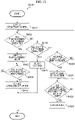
- Fig. 11 is a flowchart illustrating a flow of control processing executed by the control device 110.
- the CPU 111 executes the control program 130 read from the storage device 113. As a result, the CPU 111 functions as the UI control unit 141 and the function control unit 144, and starts the control processing.
- the UI control unit 141 causes the display unit 121 of the touch panel display 123 to display the task selection screen 300 (see Fig. 4 ) as the top screen (Step S301). Specifically, the UI control unit 141 reads the priority list information 11, the history list information 12, and the UI control data 132 included in the function control data 131, and generates the task selection screen 300 including the priority list 1 and the history list 2. A plurality of task items 301 included in each of the priority list 1 and the history list 2 are displayed in the task selection screen 300.
- the UI control unit 141 waits for input of a touch operation for the task selection screen 300 displayed on the display unit 121. First, in Step S302, the UI control unit 141 determines whether or not a scrolling operation for the task selection screen 300 has been performed. In a case where a task item 301 desired by a user is hidden in the task selection screen 300, the user performs a scrolling operation for the task selection screen 300 through the touch panel display 123 in order to display the hidden task item 301.
- the scrolling operation is, for example, a flicking operation in the direction along the arrow X1.
- Step S303 the UI control unit 141 scrolls through the task selection screen 300 (Step S303). More specifically, in Step S303, the UI control unit 141 handles the priority list 1 and the history list 2 as one integrated list, and integrally scrolls through the priority list 1 and the history list 2. For example, when a user performs the scrolling operation, both the priority list 1 and the history list 2 are scrolled regardless of whether the finger of the user touches a display region of the priority list 1 or a display region of the history list 2 on the touch panel display 123, because the priority list 1 and the history list 2 are handled as one integrated list.
- the task items are hidden from a task item 301 arranged at the uppermost portion of the priority list 1, and instead, a hidden task item 301 positioned below a task item 301 at the lowermost portion of the history list 2 enters the display region and is displayed.
- the task selection screen 300 is changed from the state illustrated in Fig. 4 to the state illustrated in Fig. 6 .
- a user searches for a desired task item 301 in the task selection screen 300 by performing such a scrolling operation.
- Step S302 NO
- Step S303 the scrolling operation is performed in Step S303 and then the scrolling operation is stopped
- Step S304 the UI control unit 141 proceeds to Step S304.
- Step S304 the UI control unit 141 determines whether or not an operation (specifically, a flicking operation or a tapping operation) for the setting button 6 of the priority list 1 has been performed.
- an operation specifically, a flicking operation or a tapping operation
- Step S400 the UI control unit 141 processing of editing the priority list 1 to be described later.
- Step S304 determines whether or not an operation (specifically, a flicking operation or a tapping operation) for the setting button 8 of the history list 2 has been performed (Step S305).
- Step S305 YES
- the UI control unit 141 executes processing of editing the history list 2 to be described later (Step S500).
- Step S305 NO
- the UI control unit 141 proceeds to Step S306.
- Step S306 the UI control unit 141 determines whether or not a selection operation for any task item 301 in the task selection screen 300 has been performed. In a case where the selection operation for any of the task items 301 has been performed (Step S306: YES), the UI control unit 141 proceeds to Step S600 and executes processing of displaying the task execution screen 350 (see Fig. 5 ) corresponding to the function of the selected task item 301. After executing Step S600, the UI control unit 141 returns to Step S301 and waits for input of a touch operation.
- Step S306 in a case where no task item 301 is selected (Step S306: NO), the UI control unit 141 returns to Step S302 and repeats the above-described processing.
- the control processing illustrated in Fig. 11 ends, for example, in a case where the power supply of the multi-function peripheral 100 is turned off, regardless of which step is being executed.
- Fig. 12 is a flowchart illustrating a flow of processing of editing the priority list 1 (Step S400 in Fig. 11 ) executed by the control device 110.
- the UI control unit 141 displays the registration menu 7 (see Fig. 7 ) in the task item 301 for which the setting button 6 has been operated (Step S401).
- the rearrangement button 7a, the delete button 7b, and the name change button 7c are arranged in the registration menu 7.
- Step S402 determines whether or not an operation (specifically, a flicking operation or a tapping operation) for the rearrangement button 7a has been performed.
- Step S402 determines whether or not an operation for the rearrangement button 7a has been performed.
- Step S402 shifts the task selection screen displayed on the display unit 121 to the rearrangement mode (Step S403).
- Step S402 in a case where the operation for the rearrangement button 7a is not performed (Step S402: NO), the UI control unit 141 proceeds to Step S410.
- a moving operation (specifically, a dragging operation) for a task item 301 in the priority list 1 is enabled as indicated by an arrow A in Fig. 8 .
- the UI control unit 141 determines whether or not a moving operation for a task item 301 of the priority list 1 in the task selection screen 300 has been performed in the rearrangement mode (Step S404). In a case where the moving operation for a task item 301 of the priority list 1 in the task selection screen 300 has been performed (Step S404: YES), the UI control unit 141 moves the task item 301 of the priority list 1 to change the arrangement order of the task items 301 (Step S405). In a case where the moving operation for a task item 301 of the priority list 1 in the task selection screen 300 is not detected (Step S404: NO), the UI control unit 141 repeats Step S404.
- Step S410 the UI control unit 141 determines whether or not an operation (specifically, a flicking operation or a tapping operation) for the delete button 7b has been performed (Step S410). In a case where the operation for the delete button 7b has been performed (Step S410: YES), the UI control unit 141 deletes a task item 301 of the priority list 1 (Step S411). In a case where the operation for the delete button 7b is not performed (Step S410: NO), the UI control unit 141 proceeds to Step S420.
- an operation specifically, a flicking operation or a tapping operation
- Step S420 the UI control unit 141 determines whether or not an operation (specifically, a flicking operation or a tapping operation) for the name change button 7c has been performed. In a case where the operation for the name change button 7c has been performed (Step S420: YES), the UI control unit 141 shifts the task selection screen 300 to the name input screen (not illustrated) (Step S421). In a case where the operation for the name change button 7c is not performed (Step S420: NO), the UI control unit 141 returns to Step S402.
- an operation specifically, a flicking operation or a tapping operation
- Step S423 determines whether or not a confirmation operation has been performed after the input of the new name in the name input screen.
- the UI control unit 141 changes the name of the task item 301 of the priority list 1 (Step S424).
- Step S423: NO the CPU 111 repeats Step S423.
- the UI control unit 141 ends the editing processing illustrated in Fig. 12 regardless of which step is being executed. Once the editing processing illustrated in Fig. 12 ends, the UI control unit 141 returns to Step S301 in Fig. 11 .
- Step S400 the processing of editing the priority list 1 (Step S400) ends after the processing of each of Step S405, Step S411, and Step S424 is completed once. However, after the processing of each of Step S405, Step S411, and Step S424 is completed once, the processing may return to Step S401 and wait for the next editing instruction.
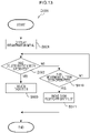
- Fig. 13 is a flowchart illustrating a flow of processing of editing the history list 2 (Step S500 in Fig. 11 ) executed by the control device 110.
- the UI control unit 141 displays the registration menu 9 (see Fig. 10 ) in the task item 301 for which the setting button 8 has been operated (Step S501).
- a delete button 9a and a movement button 9b are arranged in the registration menu 9.
- the UI control unit 141 determines whether or not an operation (specifically, a flicking operation or a tapping operation) for the delete button 9a has been detected (Step S502). In a case where the operation for the delete button 9a has been detected (Step S502: YES), the UI control unit 141 deletes a task item 301 of the history list 2 (Step S503). In a case where the operation for the delete button 9a is not performed (Step S502: NO), the UI control unit 141 proceeds to Step S510.
- an operation specifically, a flicking operation or a tapping operation
- Step S510 the UI control unit 141 determines whether or not an operation (specifically, a flicking operation or a tapping operation) for the movement button 9b has been performed. In a case where the operation for the movement button 9b has been performed (Step S510: YES), the UI control unit 141 move a task item 301 of the history list 2 to the priority list 1 (Step S511). In a case where the operation for the movement button 9b is not performed (Step S510: NO), the UI control unit 141 returns to Step S502.
- an operation specifically, a flicking operation or a tapping operation
- the UI control unit 141 ends the editing processing illustrated in Fig. 13 regardless of which step is being executed. Once the editing processing illustrated in Fig. 13 ends, the UI control unit 141 returns to Step S301 in Fig. 11 .
- Step S500 the processing of editing the history list 2 (Step S500) ends after the processing of each of Steps S503 and S511 is completed once. However, after the processing of each of Steps S503 and S511 is completed once, the processing may return to Step S501 and wait for the next editing instruction.
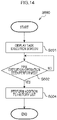
- Fig. 14 is a flowchart illustrating a flow of processing of displaying the task execution screen 350 executed by the control device 110.
- the UI control unit 141 displays the task execution screen 350 (see Fig. 5 ) (Step S601).
- the UI control unit 141 determines whether or not an instruction operation of instructing execution of a task corresponding to the selected task item (specifically, a slide operation for the slide button 10) has been performed (Step S602). In a case where the instruction operation has been performed (Step S602: YES), the UI control unit 141 proceeds to Step S604. In a case where the instruction operation is not performed (Step S602: NO), the UI control unit 141 repeats Step S602.
- the UI control unit 141 adds the task item 301 for the executed task to the history list 2 (Step S604), and ends the processing of Step S600 illustrated in Fig. 14 .
- the UI control unit 141 ends the processing of Step S600 regardless of which step is being executed. Once this processing ends, the UI control unit 141 returns to Step S301 in Fig. 11 .
- the UI control unit 141 integrally scrolls the priority list 1 and the history list 2 (Step S303). Therefore, when selecting a task item 301 in the task selection screen (see Fig. 4 ), it is not necessary to select whether to scroll through the priority list 1 or the history list 2.
- the priority list 1 and the history list 2 are scrolled along the arrow X1 in the task selection screen 300, the number of displayed task items 301 of the priority list 1 decreases, and the priority list 1 eventually disappears from the task selection screen 300. As a result, the display region of the history list 2 is enlarged, and the history list 2 is displayed in the entire screen. Since the number of task items 301 of the history list 2 increases accordingly, it is possible to quickly select a task item 301 from the history list 2. In a case where the number of task items 301 of the priority list 1 is large, the task items 301 of the priority list 1 can be displayed in the entire screen by scrolling. In this case, it is possible to quickly select a task item 301 from the priority list 1.
- any of the priority list 1 and the history list 2 does not always keep occupying a part of the display region. Therefore, it is possible to increase the size of the display region of one of the priority list 1 and the history list 2 as compared with the related art in which the priority list 1 and the history list 2 are separately scrolled.
- the plurality of task items 301 in the task selection screen 300 are task items for any of the copy function, the scanning function, the printing function, and the facsimile function. Since the task items 301 registered in the priority list 1 and the history list 2 are narrowed down to those related to the four main functions having a relatively high execution frequency in the multi-function peripheral 100, the priority list 1 and the history list 2 become easy to use for a user. At least one of the plurality of task items 301 registered in the priority list 1 or the history list 2 preferably includes a task item 301 for the copy function considered to have a relatively high execution frequency among the four main functions.
- the plurality of task items 301 include task items 301 for different functions (as an example, the copy function, the scanning function, the printing function, and the like), and as an example, each task item 301 is displayed in a different color for each function in such a manner that the color display portion 3 is arranged on the left side of each task item 301 in the task selection screen 300. Therefore, since the function of the task to be executed can be intuitively grasped by the color, the color becomes a mark for task selection, and erroneous operation can be prevented.
- the task items 301 of the priority list 1 can be rearranged, deleted, or renamed. Therefore, a user can customize a task item 301 of the priority list 1 according to a usage situation of the user, as a result of which the operability can be improved.
- a task item 301 in the priority list 1 can be initially set. Therefore, a task item 301 having a high execution frequency at the time of product shipment or the like can be included in the priority list 1. As a result, it is possible to reduce the burden of a setting work for the task item 301 on a user.
- a task item 301 in the history list 2 can be moved to the priority list 1 or deleted. Therefore, a user can customize task items 301 of the priority list 1 and the history list 2 according to a usage situation of the user, as a result of which the operability can be improved.
- the same color as a color displayed for a task item 301 in the task selection screen is displayed in the task execution screen 350. Therefore, the function to be executed can be intuitively grasped by the color, as a result of which erroneous operation can be prevented.
- various processors described below can be used as a hardware structure of a processing unit that executes various processings such as the UI control unit 141, the display control unit 142, the operation receiving unit 143, and the function control unit 144.
- the various processors include, in addition to the CPU 111 which is a general-purpose processor that functions as various processing units by executing software (program), a programmable logic device (PLD) in which a circuit configuration can be changed after manufacturing, such as a field programmable gate array (FPGA) and a dedicated circuitry which is a processor having a dedicated circuit configuration designed for executing specific processing, such as an application specific integrated circuit (ASIC).
- the CPU 111 which is a general-purpose processor that functions as various processing units by executing software (program), a programmable logic device (PLD) in which a circuit configuration can be changed after manufacturing, such as a field programmable gate array (FPGA) and a dedicated circuitry which is a processor having a dedicated circuit configuration designed for executing specific processing,
- the various processings may be executed by one of these various processors, or may be executed by a combination of two or more processors of the same type or different types (for example, a plurality of FPGAs and a combination of a CPU and an FPGA).
- a plurality of processing units may be implemented by one processor.
- a processor that implements a function of the entire system including a plurality of processing units with one integrated circuit (IC) chip, such as a system on chip (SoC), may be used.
- IC integrated circuit
- the various processing units are implemented using one or more of the various processors as a hardware structure.
- circuitry obtained by combining circuit elements such as semiconductor elements can be used as the hardware structure of these various processors.
- the technology of the disclosure is also applicable to a computer-readable storage medium (a universal serial bus (USB) memory, a digital versatile disc (DVD)-read only memory (ROM), or the like) that non-transiently stores a control program of the control device, in addition to the control program of the control device.
- a computer-readable storage medium a universal serial bus (USB) memory, a digital versatile disc (DVD)-read only memory (ROM), or the like
- the present invention is not limited to the above-described embodiments, and various modifications, changes, and improvements can be made without departing from the gist of the disclosure.
- the above-described modified examples may be configured by combining a plurality of embodiments, if appropriate.
- the multi-function peripheral 100 is used as an example of the information apparatus, but the technology of the disclosure is not limited thereto.
- the information apparatus may include a telephone line apparatus such as a mobile phone or a facsimile machine, a copier or a printer having no communication function, or the like may be used, or an image forming device other than a multi-function peripheral may be used as an example of the information apparatus.
- the technology of the disclosure is capable of integrally scrolling through the priority list and the history list, and is capable of maximizing a scrolling region and displayable task items, so that a task can be quickly selected. That is, the operability of the information apparatus is enhanced, and the technology of the disclosure has industrial applicability.
Landscapes
- Engineering & Computer Science (AREA)
- Human Computer Interaction (AREA)
- General Engineering & Computer Science (AREA)
- Theoretical Computer Science (AREA)
- Multimedia (AREA)
- Signal Processing (AREA)
- Physics & Mathematics (AREA)
- General Physics & Mathematics (AREA)
- User Interface Of Digital Computer (AREA)
- Telephone Function (AREA)
- Facsimiles In General (AREA)
- Accessory Devices And Overall Control Thereof (AREA)
Abstract
Description
- The technology of the present disclosure relates to a control device and a control program.
- As an information apparatus, a so-called multi-function peripheral that executes a plurality of functions such as a copy function, a scanning function, a facsimile function, and a printing function is known. A technology in which tasks used in the past are displayed as a history list has been widely used in order to enable easy and quick selection of a function to be executed by such an information apparatus such as a multi-function peripheral. There is also a technology in which a task with a particularly high execution frequency is preferentially displayed.
- Japanese Patent Application Laid-Open (
JP-A) No. 2006-185351 - In the technology disclosed in
JP-A No. 2006-185351 - Here, even in a case where it is necessary to separately scroll through a priority list (corresponding to the fixed menu) that is a list of preset task items and a history list (corresponding to the history menu item) that includes task items executed in the past, it is necessary to select which list to scroll through.
- An object of the technology of the disclosure is to provide a control device and a control program capable of eliminating the need to select which of a priority list and a history list to scroll through.
- A first aspect is a control device including a display control unit that controls display of a task selection screen which is a task selection screen for selecting one task item from a plurality of task items and in which a priority list, which is a list of preset task items, and a history list, which includes histories of task items executed in the past, are displayed in parallel, in which the display control unit is configured to integrally scroll through the priority list and the history list.
- A second aspect is the control apparatus according to the first aspect, in which the one task item is a task item for any of a copy function, a scanning function, a printing function or a facsimile function.
- A third aspect is the control device according to the first or second aspect, in which the plurality of task items include task items for different functions, and the task item is displayed in a color different for each function at the task selection screen.
- A fourth aspect is the control device according to any one of the first to third aspects, in which a setting button is arranged at the task item in the priority list, and the display control unit is configured to perform one or more of rearrangement of the task items in the priority list, deletion of the task item from the priority list or name change of the task item, based on an operation of the setting button.
- A fifth aspect is the control device according to any one of the first to fourth aspects, in which the task item in the priority list is initially settable.
- A sixth aspect is the control device according to any one of the first to third aspects, in which a setting button is arranged at the task item in the history list, and the display control unit is configured to perform one or more of movement to the priority list or deletion from the priority list, based on an operation of the setting button.
- A seventh aspect is the control device according to the third aspect, in which in a case in which a desired task item is selected, transition is made to a task execution screen for the selected task item, and the task execution screen is displayed in the same color as a color in which the task item is displayed.
- An eighth aspect is a control program for causing a computer to function as a control device, the control device including a display control unit that controls display of a task selection screen which is a task selection screen for selecting one task item from a plurality of task items and in which a priority list, which is a list of preset task items, and a history list, which includes histories of task items executed in the past, are displayed in parallel, in which the display control unit is configured to integrally scroll through the priority list and the history list.
- According to the technology of the disclosure, it is not necessary to select which of the priority list and the history list to scroll through.
-
-
Fig. 1 is an exterior view of a multi-function peripheral. -
Fig. 2 is a block diagram illustrating a hardware configuration of the multi-function peripheral. -
Fig. 3 is a block diagram illustrating a functional configuration of a control device. -
Fig. 4 is a view illustrating a task selection screen. -
Fig. 5 is a view illustrating a task execution screen. -
Fig. 6 is a view illustrating a state in which a priority list and a history list are scrolled. -
Fig. 7 is a view illustrating a state in which a setting button is displayed in a task item of the priority list. -
Fig. 8 is a view illustrating a screen in a rearrangement mode. -
Fig. 9 is a view illustrating another example of the setting button displayed in the task item of the priority list. -
Fig. 10 is a view illustrating a state in which the setting button is displayed in a task item in the history list. -
Fig. 11 is a flowchart illustrating a flow of display control processing. -
Fig. 12 is a flowchart illustrating a flow of processing of editing the priority list. -
Fig. 13 is a flowchart illustrating a flow of processing of editing the history list. -
Fig. 14 is a flowchart illustrating a flow of processing of displaying the execution screen. - Hereinafter, an example of an embodiment of the technology of the present disclosure will be described with reference to the drawings.
-
Fig. 1 is a view illustrating an appearance of the multi-function peripheral 100 according to the present embodiment.Fig. 2 is a block diagram illustrating a hardware configuration of the multi-function peripheral 100. - The multi-function peripheral 100 illustrated in
Figs. 1 and2 is a device capable of executing processing for functions such as copying, printing, scanning, and facsimile. As illustrated inFig. 2 , the multi-function peripheral 100 includes acontrol device 110, areading unit 102, animage forming unit 103, and acommunication unit 104 in amain body 150. Note that the multi-function peripheral 100 is an example of the information apparatus. The multi-function peripheral 100 can perform data communication with an information processing apparatus such as a personal computer or a server in an office connected to a local area network (LAN) line or the like or perform facsimile communication with a communication apparatus in another office through a public line such as a telephone line. Therefore, the multi-function peripheral 100 is also an example of the information communication apparatus. - An
operation panel 120, thecontrol device 110 including astorage device 113, thereading unit 102, theimage forming unit 103, and thecommunication unit 104 are mutually connected by abus 109. Each unit of the multi-function peripheral 100 will be described below. - The
reading unit 102 reads an image of a document. Specifically, thereading unit 102 generates image data by optically reading an image of a document and converting the image into a digital signal. - The
image forming unit 103 forms an image on a medium such as a paper sheet. Specifically, theimage forming unit 103 forms an image on a medium by, for example, an electrophotographic method in which an image is formed by electrostatically attaching a toner onto a paper sheet. Note that theimage forming unit 103 may form an image on a medium by another method such as an inkjet method in which an image is formed by ejecting an ink onto a paper sheet. - The
communication unit 104 communicates with an external device such as another facsimile device. Specifically, thecommunication unit 104 transmits and receives various pieces of data to and from an external device by communication using various wired or wireless communication lines. Examples of the communication line include the Internet, an intranet, and a public telephone line. - For example, the multi-function peripheral 100 includes a
document feeding device 151 provided at an upper portion of themain body 150 as illustrated inFig. 1 . Thedocument feeding device 151 feeds a document to a document reading stage (not illustrated) disposed on an upper surface of themain body 150. Thereading unit 102 is disposed at a position facing the reading stage in themain body 150. Thedocument feeding device 151 can be lifted up. As thedocument feeding device 151 is lifted up, the reading stage is exposed and can be used as a so-called flatbed type. Therefore, a user can directly set a document on the reading stage without using thedocument feeding device 151. - An image of a document is read by the
reading unit 102, and image data is generated. In a case where processing related to the copy function is executed in the multi-function peripheral 100, theimage forming unit 103 prints an image of a document on another paper sheet based on image data generated by thereading unit 102. The paper sheet on which an image is printed is discharged to a papersheet discharging unit 152 provided in themain body 150. In a case where processing related to the facsimile function is executed in the multi-function peripheral 100, image data generated by thereading unit 102 is output to thecommunication unit 104 and transmitted to a destination via thecommunication unit 104. In a case where processing related to the printing function is executed in the multi-function peripheral 100, theimage forming unit 103 prints an image on a paper sheet based on image data input from a personal computer or the like. The paper sheet on which an image is printed is discharged to the papersheet discharging unit 152. - In addition, a feeding unit in which a paper sheet is loaded, a paper sheet transport mechanism that transports a paper sheet to the
image forming unit 103 and the papersheet discharging unit 152, and the like are provided inside themain body 150. - The multi-function peripheral 100 includes the
operation panel 120 for a user to operate the multi-function peripheral 100. Theoperation panel 120 is an example of a user interface. The user interface is a device for exchanging information between the multi-function peripheral 100 and a user, specifically, for inputting an operation instruction from a user to the multi-function peripheral 100 or displaying information such as a status of the multi-function peripheral 100 to a user. - In the present embodiment, specifically, the
operation panel 120 includes adisplay unit 121 and anoperation unit 122 as illustrated inFigs. 2 and3 . - The
display unit 121 displays an operation screen, various messages such as operation guidance, and the like. Theoperation unit 122 is a component on which a user performs an input operation. Thedisplay unit 121 is implemented by, for example, a liquid crystal display, an organic electro luminescence (EL) display, or the like. Theoperation unit 122 and thedisplay unit 121 are implemented by atouch panel display 123 in which both theoperation unit 122 and thedisplay unit 121 are integrated. Theoperation unit 122 is a resistive type touch panel, a capacitive type touch panel, or the like, and detects a touch operation of a user. A region where an operation screen of thedisplay unit 121 is displayed and a region where a touch operation of theoperation unit 122 can be detected overlap with each other in thetouch panel display 123. As a result, once a user performs a touch operation on an operation screen displayed on thedisplay unit 121, theoperation unit 122 detects the touch operation performed on the operation screen and a position at which the touch operation is performed on the operation screen, and outputs a detection signal to thecontrol device 110. - Examples of the touch operation of the user include operations such as tapping, flicking, sliding, and dragging. The tapping operation is an operation of touching the screen of the
display unit 121 with a finger. The flicking operation is an operation of touching the screen of thedisplay unit 121 in such a way as to flick the screen with a finger. The sliding operation is an operation of moving a finger in a state of touching the screen of thedisplay unit 121 with the finger. The dragging operation is an operation for moving an image such as an icon displayed on thedisplay unit 121. The dragging operation is an operation of touching an image displayed on thedisplay unit 121 with a finger, then moving the finger touching the image, and then releasing the finger from the image. Theoperation unit 122 that is a touch panel outputs, as a detection signal, a movement locus of a finger associated with these touch operations in an operation screen. Note that the touch operation may be not only an operation using a finger of a user but also an operation using a tool such as a touch pen. - The
operation panel 120 further includes anoperation key 124 disposed outside the screen of thedisplay unit 121 as illustrated inFig. 1 . Examples of theoperation key 124 include a power key for supplying power to the multi-function peripheral 100, a cancel key for canceling various executions, and the like. As described above, theoperation panel 120 according to the present embodiment includes a mechanical operation unit in addition to thetouch panel display 123 including theoperation unit 122. - In the present embodiment, the
display unit 121 can display various operation screens such as atask selection screen 300 illustrated inFig. 4 and atask execution screen 350 illustrated inFig. 5 , for example. Details of thetask selection screen 300 and thetask execution screen 350 will be described later. - The
control device 110 is a device that controls each unit of the multi-function peripheral 100 including theoperation panel 120. Specifically, thecontrol device 110 includes a central processing unit (CPU) 111, amemory 112, and astorage device 113 as illustrated inFig. 2 . Thecontrol device 110 controls the multi-function peripheral 100 based on information stored in thestorage device 113. - The
storage device 113 stores various programs including acontrol program 130 and various pieces of data includingfunction control data 131 and user interface (UI)control data 132. Thecontrol program 130 is a program that causes a computer including theCPU 111 to function as thecontrol device 110. Thefunction control data 131 is data used to control thereading unit 102, theimage forming unit 103, and thecommunication unit 104, and includes various pieces of setting information, processing parameters, and the like. The processing parameter is, for example, a parameter used when image correction processing such as gain correction, contrast correction, white balance correction, or gamma correction is executed. - The various pieces of setting information include setting information that specifies processing conditions for each of the copy function, the scanning function, the printing function, and the like implemented by the
reading unit 102, theimage forming unit 103, and thecommunication unit 104. For example, in the case of the copy function and the printing function, the setting information is setting information that specifies processing conditions such as paper sheet size setting and color setting (for example, black-and-white copy or color copy), and in the case of the scanning function, the setting information is setting information that specifies processing conditions such as reading resolution setting and color setting (for example, black-and-white reading or color reading). The setting information includes user setting information set by a user in addition to initial setting information. The various pieces of setting information also include a history of user setting information used by a user in the past. - The
UI control data 132 includes various pieces of screen data for configuring an operation screen displayed by thedisplay unit 121 and various pieces of table data defining various setting items and the like displayed in an operation screen. Specifically, thestorage device 113 is implemented by a recording device such as a hard disk drive (HDD), a solid state drive (SSD), or a flash memory. - The
memory 112 is a work area for theCPU 111 to execute various programs, and temporarily records various programs or various pieces of data when theCPU 111 executes processing. TheCPU 111 reads various programs including thecontrol program 130 from thestorage device 113 to thememory 112, and executes the program by using thememory 112 as a work area. - In the
control device 110, theCPU 111 executes thecontrol program 130 to implement various functions for controlling the multi-function peripheral 100. Hereinafter, a functional configuration implemented by cooperation of theCPU 111 as a hardware resource and thecontrol program 130 as a software resource will be described.Fig. 3 is a block diagram illustrating a functional configuration of theCPU 111, and is a block diagram mainly illustrating a functional configuration that implements control of theoperation panel 120. - As illustrated in
Fig. 3 , in thecontrol device 110, theCPU 111 functions as aUI control unit 141 and afunction control unit 144 by executing thecontrol program 130. - The
function control unit 144 controls thereading unit 102, theimage forming unit 103, and thecommunication unit 104 while referring to the function control data based on an operation instruction input from theUI control unit 141. In addition, thefunction control unit 144 outputs, to theUI control unit 141, a processing execution result in thereading unit 102, theimage forming unit 103, and thecommunication unit 104, a status, and the like. - The
UI control unit 141 receives an operation instruction input from theoperation panel 120 and outputs the received operation instruction to thefunction control unit 144. TheUI control unit 141 controls thetouch panel display 123. TheUI control unit 141 includes adisplay control unit 142 and anoperation receiving unit 143 as the functional configuration. - The
operation receiving unit 143 receives an operation instruction according to a user's operation input from theoperation panel 120, the user's operation input including a user's touch operation detected by theoperation unit 122 of thetouch panel display 123. - The
display control unit 142 performs control to display various operation screens on thedisplay unit 121 of thetouch panel display 123 with reference to thefunction control data 131 and theUI control data 132. - Specifically, once the
operation receiving unit 143 receives an operation of supplying power to the multi-function peripheral 100, thedisplay control unit 142 causes thedisplay unit 121 to display the task selection screen 300 (seeFig. 4 ) as a top screen, as an example. Thetask selection screen 300 is a screen for a user to select and operate a task item 301 (seeFig. 4 ) to be executed by the multi-function peripheral 100. Here, a task is processing executed by the multi-function peripheral 100 after a user sets a processing condition for a main function of the multi-function peripheral 100. Then, an item including information indicating the content of this processing is referred to as thetask item 301. For example, in the case of the copy function, which is one of the main functions of the multi-function peripheral 100, processing executed by the multi-function peripheral 100 after a user sets the processing conditions such as paper sheet size setting and color setting is the task of the copy function, and an item indicating the content of the task is thetask item 301. Similarly, in the case of the scanning function, processing executed by the multi-function peripheral 100 after a user sets the processing conditions such as reading resolution setting and color setting is the task of the scanning function, and an item indicating the content of the task is thetask item 301. - As described above, there are various types of tasks and
task items 301 indicating the contents of the tasks according to the type of function and the processing condition. A plurality oftask items 301 for different types of functions and different processing conditions are displayed in thetask selection screen 300. Thetask selection screen 300 is a selection screen for selecting onetask item 301 from the plurality oftask items 301 in the case of causing the multi-function peripheral 100 to execute one task. - Various pieces of setting information of the
function control data 131 includepriority list information 11 andhistory list information 12. Thestorage device 113 is a priority list recording unit in which thepriority list information 11 is recorded and a history list recording unit in which thehistory list information 12 is recorded. Thepriority list information 11 is information in which a plurality ofpreset task items 301 are recorded. Thetask items 301 included in thepriority list information 11 include, for example, task items that are preset due to a high execution frequency. Thetask items 301 included in thepriority list information 11 may be initially set at the time of product shipment or may be set by a user. - The
history list information 12 is information in which histories of thetask items 301 executed in the past by the multi-function peripheral 100 are recorded. The name of eachtask item 301, an arrangement order, and the like are recorded in thepriority list information 11. The name of eachtask item 301, an execution date and time when eachtask item 301 was executed, and the like are recorded in thehistory list information 12. - The
display control unit 142 generates thetask selection screen 300 including apriority list 1 and ahistory list 2 with reference to thepriority list information 11 and thehistory list information 12. Specifically, when generating thepriority list 1, thedisplay control unit 142 generates thepriority list 1 by arranging thetask items 301 of thepriority list 1 in order based on the name and the arrangement order of eachtask item 301 included in thepriority list information 11. When generating thehistory list 2, thedisplay control unit 142 generates thehistory list 2 by arranging thetask items 301 of thehistory list 2 in order based on the name and the execution date and time of eachtask item 301 included in thehistory list information 12. Thedisplay control unit 142 displays thepriority list 1 and thehistory list 2 in parallel in thetask selection screen 300. - As a result, as illustrated in
Fig. 4 , thedisplay control unit 142 displays thepriority list 1 that is a list ofpreset task items 301, and thehistory list 2 that includes histories oftask items 301 executed in the past in the multi-function peripheral 100, in parallel in thetask selection screen 300. InFig. 4 , as an example, thepriority list 1 is displayed above thehistory list 2 in thetask selection screen 300. - The
task items 301 of thehistory list 2 are displayed in time series based on the execution date and time of eachtask item 301 recorded in thehistory list information 12. Specifically, as an example, thetask items 301 are displayed in a direction along an arrow X2 in order from atask item 301 with the latest execution date and time. Therefore, the most recently executedtask item 301 is displayed at the uppermost portion of the history list 2 (that is, a position closest to an X1 direction side). - As described above, each of the plurality of
task items 301 included in thepriority list 1 or thehistory list 2 is a task item for any of the four main functions of the multi-function peripheral 100, that is, the copy function, the scanning function, the printing function, and the facsimile function. In this manner, thetask item 301 registered in thepriority list 1 or thehistory list 2 corresponds to any of the four main functions of the multi-function peripheral 100. In other words, supplementary functions of the multi-function peripheral 100 other than the main four functions are excluded from the functions registered in thepriority list 1 or thehistory list 2. Therefore, since thetask items 301 registered in thepriority list 1 and thehistory list 2 are narrowed down to those related to main functions having a relatively high execution frequency, thepriority list 1 and thehistory list 2 become easy to use for a user. At least one of the plurality oftask items 301 registered in thepriority list 1 or thehistory list 2 preferably includes atask item 301 for the copy function considered to have a relatively high execution frequency among the four main functions. - The
task item 301 of thepriority list 1 can be customized by a user. Specifically, rearrangement of thetask items 301 in thepriority list 1, name change, and addition of atask item 301 from thehistory list 2 can be made as will be described later. - The
function control unit 144 adds data of an executedtask item 301 to thehistory list information 12 every time atask item 301 is executed by the multi-function peripheral 100. In a case where thehistory list information 12 is updated, thedisplay control unit 142 updates thehistory list 2 in thetask selection screen 300. - A
setting button 8 for displaying a registration menu 9 (seeFig. 10 ) is displayed on the right side of atask item 301 of thehistory list 2 in thetask selection screen 300. - A pinning
mark 5 indicating that it is atask item 301 of thepriority list 1 and asetting button 6 for displaying a registration menu 7 (seeFig. 7 ) are displayed on the right side of atask item 301 of thepriority list 1. The pinningmark 5 indicates it is atask item 301 whose display is not updated even when another task item is executed. - As illustrated in
Fig. 4 , for example, "black-and-white copy" 1a, "color copy" 2a, "facsimile" 2b, "scanning" 2c, and the like are displayed as thetask items 301 in thetask selection screen 300 according to the present embodiment. A user name is also displayed in thetask items 301, "fax" 2b and "scanning" 2c. "Black-and-white copy" 1a having a high execution frequency is displayed in thepriority list 1. - A
color display portion 3 colored in a specific color is arranged on the left side of eachtask item 301. Thecolor display portions 3 arranged in "black-and-white copy" 1a and "color copy" 2a, which are the same copy functions, are displayed in the same color. In other words, the plurality oftask items 301 include task items for a plurality of functions selected from the four main functions of the multi-function peripheral 100, that is, the copy function, the fax function, the scanning function, and the printing function, and thetask item 301 is displayed in a different color for each function in thetask selection screen 300. In the present embodiment, a plurality oftask items 301 corresponding to the same function are bundled as the same type oftask items 301, and the same color is assigned.Task items 301 to be bundled as the same type oftask items 301 are set in advance. For example, information regarding whichtask items 301 are set as the same type oftask items 301 and which color is assigned to the task items is recorded in the table data of theUI control data 132. Thedisplay control unit 142 displays thecolor display portion 3 with reference to the data. By doing so, the color of thecolor display portion 3 is determined, and thecolor display portion 3 is displayed. As an example other than the example in whichtask items 301 for the same corresponding functions are bundled as the same type oftask items 301, "fax" 2b and "scan" 2c, which are thetask items 301 with the same "user", may be set as the same type oftask items 301, and the same color may be assigned to thesetask items 301. The color of thecolor display portion 3 may be changed by a setting change operation performed by a user. - As described above, in the
task selection screen 300, thepriority list 1 and thehistory list 2 are displayed in the sametask selection screen 300. - The
task selection screen 300 may display a list for each user as thepriority list 1 and thehistory list 2. In this case, for example, as user authentication is performed via theoperation unit 122, thedisplay unit 121 displays thepriority list 1 and thehistory list 2 of the authenticated user in the task selection screen. In this case, thepriority list information 11 is information corresponding to thepriority list 1 associated with each user, and atask item 301 included in thepriority list information 11 for each user can be set for each user. Thehistory list information 12 is information corresponding to thehistory list 2 associated with each user, and atask item 301 included in thehistory list information 12 for each user is updated based on the history for each user. - Once the
operation unit 122 detects a scrolling operation for thepriority list 1 or thehistory list 2 in thetask selection screen 300, theoperation receiving unit 143 receives an operation instruction for the scrolling operation. This operation instruction is input to thedisplay control unit 142. Thedisplay control unit 142 integrally scrolls through thepriority list 1 and thehistory list 2 as illustrated inFig. 6 based on the input operation instruction for the scrolling operation. Specifically, the scrolling operation is a flicking operation in a direction along an arrow X1 or a direction along an arrow X2 (seeFig. 4 ). - As described above, when scrolling through the two lists of the
priority list 1 and thehistory list 2 in thetask selection screen 300, thedisplay control unit 142 integrally handles thepriority list 1 and thehistory list 2 as an integrated list. In other words, at the time of scrolling, thepriority list 1 and thehistory list 2 are scrolled as one integrated list without being distinguished from each other. - The scrolling operation can be performed only in the X1 direction in which the number of displayed
task items 301 of thepriority list 1 decreases in the state illustrated inFig. 4 in thetask selection screen 300. Therefore, only a flicking operation in the X1 direction is valid in the state illustrated inFig. 4 in thetask selection screen 300. Thepriority list 1 and thehistory list 2 can also be scrolled in the X2 direction after being scrolled in the X1 direction. - The scrolling operation for the
priority list 1 and thehistory list 2 is performed by moving thepriority list 1 and thehistory list 2 in the X1 direction or the X2 direction for which the flicking operation has been performed. As a result,task items 301 that have not been displayed are sequentially displayed in thetask selection screen 300.Fig. 6 illustrates a state in which thepriority list 1 and thehistory list 2 have been moved by onetask item 301 in the direction along the arrow X1 in the state illustrated inFig. 4 . As described above, in the present embodiment, thepriority list 1 and thehistory list 2 can be scrolled integrally in the scrolling of thetask selection screen 300. - The
setting button 6 is arranged in atask item 301 in thepriority list 1. Thedisplay control unit 142 can execute one or more of deletion of atask item 301 from thepriority list 1 and name change of atask item 301 based on the operation of thesetting button 6. - For example, once the
operation unit 122 detects an operation (specifically, a flicking operation or a tapping operation) for thesetting button 6 of thepriority list 1, theoperation receiving unit 143 receives an operation instruction for the operation of thesetting button 6. Thedisplay control unit 142 displays theregistration menu 7 as illustrated inFig. 7 based on the operation instruction received by theoperation receiving unit 143. Arearrangement button 7a, adelete button 7b, and aname change button 7c of atask item 301 are arranged in theregistration menu 7. - Once the
operation unit 122 detects an operation (specifically, a flicking operation or a tapping operation) for therearrangement button 7a, theoperation receiving unit 143 receives an operation instruction for the operation of therearrangement button 7a. Thedisplay control unit 142 shifts thetask selection screen 300 displayed on thedisplay unit 121 to a rearrangement mode based on the operation instruction received by theoperation receiving unit 143. Once thetask selection screen 300 shifts to the rearrangement mode, a moving operation (specifically, a dragging operation) for atask item 301 in thepriority list 1 is enabled as indicated by an arrow A inFig. 8 . - Once the
operation unit 122 detects the moving operation for atask item 301 in thepriority list 1 in thetask selection screen 300 in the rearrangement mode, theoperation receiving unit 143 receives an operation instruction for the moving operation. Thedisplay control unit 142 changes the arrangement order of thetask items 301 by moving atask item 301 in thepriority list 1 based on the operation instruction received by theoperation receiving unit 143. - That is, once the
operation unit 122 detects a dragging operation, thedisplay control unit 142 rewrites the arrangement order of thetask items 301 recorded in thepriority list information 11, and displays thepriority list 1 in the rewritten arrangement order. Thedisplay control unit 142 may cancel the rearrangement mode and display the originaltask selection screen 300 after a predetermined time elapses. - A rearrangement button 7al (see
Fig. 9 ) having a movement instruction function of moving atask item 301 to the uppermost portion of thepriority list 1 may be used as therearrangement button 7a. In the example illustrated inFig. 9 , once theoperation unit 122 detects an operation (specifically, a flicking operation or a tapping operation) for the rearrangement button 7a1, thedisplay control unit 142 moves atask item 301 for which the rearrangement button 7al has been operated to the uppermost portion of thepriority list 1 and displays thepriority list 1. In the example illustrated inFig. 9 , since atask item 301 can be moved without shifting to the rearrangement mode, the operation is simplified. - Once the
operation unit 122 detects an operation (specifically, a flicking operation or a tapping operation) for thedelete button 7b, thedisplay control unit 142 deletes atask item 301 of thepriority list 1. That is, once theoperation unit 122 detects an operation for thedelete button 7b, onetask item 301 instructed to be deleted is deleted from thepriority list information 11, and thedisplay control unit 142 displays thepriority list 1 based on thepriority list information 11 after the deletion. Thedisplay control unit 142 displays thepriority list 1 and thehistory list 2 from which a place generated due to the deletion is removed. That is, thedisplay control unit 142 increases the number oftask items 301 in thehistory list 2 by the number oftask items 301 deleted from thepriority list 1, and displays anew priority list 1 andhistory list 2 whose numbers oftask items 301 have been changed. - Once the
operation unit 122 detects an operation (specifically, a flicking operation or a tapping operation) for thename change button 7c, thedisplay control unit 142 shifts thetask selection screen 300 to a name input screen (not illustrated). Once thetask selection screen 300 shifts to the name input screen, a new changed name can be input. Specifically, for example, a keyboard screen is displayed as a name input screen, and a new name can be input through the keyboard. The keyboard screen is provided with, for example, a confirm button and a cancel button. - Once the
operation unit 122 detects a confirmation operation (specifically, a flicking operation or a tapping operation for the confirm button) after the input of a new name in the name input screen, thedisplay control unit 142 changes the name of thetask item 301 of thepriority list 1. That is, once theoperation unit 122 detects the confirmation operation after a new name is input, thedisplay control unit 142 changes the name of atask item 301 recorded in thepriority list information 11, and thedisplay control unit 142 displays thetask item 301 based on data of the changed name of thetask item 301. - In this manner, setting of a
task item 301 in thepriority list 1 can be changed by a user. Atask item 301 in thepriority list 1 may be initially set at the time of product shipment. In this case, for example, thetask item 301 having a high execution frequency is generally set. The initial setting information is recorded in thepriority list information 11 as described above. - The
setting button 8 is arranged in atask item 301 in thehistory list 2. Once theoperation unit 122 detects an operation (specifically, a flicking operation or a tapping operation) for thesetting button 8 of thehistory list 2, thedisplay control unit 142 displays theregistration menu 9 as illustrated inFig. 10 . Adelete button 9a and amovement button 9b are arranged in theregistration menu 9. - Once the
operation unit 122 detects an operation (specifically, a flicking operation or a tapping operation) for thedelete button 9a, thedisplay control unit 142 deletes atask item 301 of thehistory list 2. That is, once theoperation unit 122 detects an operation for thedelete button 9a, onetask item 301 instructed to be deleted is deleted from thehistory list information 12, and thedisplay control unit 142 displays thehistory list 2 based on thehistory list information 12 after the deletion. Thedisplay control unit 142 displays thehistory list 2 from which a place generated due to the deletion is removed. That is, thedisplay control unit 142 adds ahidden task item 301 to thehistory list 2 instead of thetask item 301 deleted from thehistory list 2 and displays anew history list 2. - Once the
operation unit 122 detects an operation (specifically, a flicking operation or a tapping operation) for themovement button 9b, thedisplay control unit 142 moves atask item 301 of thehistory list 2 to thepriority list 1. That is, once theoperation unit 122 detects an operation for themovement button 9b, atask item 301 instructed to be moved is added to thepriority list information 11, and thedisplay control unit 142 displays anew priority list 1 based on thepriority list information 11 to which thetask item 301 is added. At this time, the arrangement order of thetask items 301 in thepriority list information 11 is rewritten so that thetask item 301 instructed to be moved is added to, for example, the lowermost portion of the priority list 1 (a position on an X2 direction side). Data of thetask item 301 moved to thepriority list 1 is deleted from thehistory list information 12. - As described above, in the present embodiment, a task item in the
history list 2 can be moved to thepriority list 1 by a moving operation performed by a user. In a case where thetask item 301 moved from thehistory list 2 to thepriority list 1 is deleted from thepriority list 1 by the operation of thedelete button 7b, the task item may be returned to thehistory list 2. - Once the
operation unit 122 detects a selection operation for atask item 301 of thepriority list 1 and thehistory list 2, thedisplay control unit 142 displays the task execution screen 350 (seeFig. 5 ) on thedisplay unit 121. - Setting items for performing various settings and a
slide button 10 for executing a task are displayed in thetask execution screen 350. Various settings are performed by operating the setting items. Acolor display portion 4 is arranged at an upper portion of the task selection screen. When displaying thetask execution screen 350, thecolor display portion 4 has the same color as that of thecolor display portion 3 of the selectedtask item 301. - The
task execution screen 350 illustrated inFig. 5 is atask execution screen 350 in a case where a selection operation for "color copy" among thetask items 301 in thetask selection screen 300 illustrated inFig. 4 is performed. Thecolor display portion 4 of the task execution screen illustrated inFig. 5 is displayed in the same color as that in which thecolor display portion 3 for "color copy" 2a of thetask item 301 is displayed, to indicate that the copy function is selected. - In the present embodiment, an instruction operation of instructing the multi-function peripheral 100 to execute tasks for various functions is a slide operation for the
slide button 10 in thetask execution screen 350. Once theoperation unit 122 detects the slide operation, theoperation receiving unit 143 instructs thefunction control unit 144 to execute a task corresponding to atask item 301 selected in thetask selection screen 300. Thefunction control unit 144 controls an operation of each of thereading unit 102, theimage forming unit 103, and thecommunication unit 104 based on this instruction, whereby a task is executed. - Next, an example of the operation according to the present embodiment will be described.
Fig. 11 is a flowchart illustrating a flow of control processing executed by thecontrol device 110. - Once the multi-function peripheral 100 is activated by receiving power, the
CPU 111 executes thecontrol program 130 read from thestorage device 113. As a result, theCPU 111 functions as theUI control unit 141 and thefunction control unit 144, and starts the control processing. - As illustrated in
Fig. 11 , as an example, theUI control unit 141 causes thedisplay unit 121 of thetouch panel display 123 to display the task selection screen 300 (seeFig. 4 ) as the top screen (Step S301). Specifically, theUI control unit 141 reads thepriority list information 11, thehistory list information 12, and theUI control data 132 included in thefunction control data 131, and generates thetask selection screen 300 including thepriority list 1 and thehistory list 2. A plurality oftask items 301 included in each of thepriority list 1 and thehistory list 2 are displayed in thetask selection screen 300. - The
UI control unit 141 waits for input of a touch operation for thetask selection screen 300 displayed on thedisplay unit 121. First, in Step S302, theUI control unit 141 determines whether or not a scrolling operation for thetask selection screen 300 has been performed. In a case where atask item 301 desired by a user is hidden in thetask selection screen 300, the user performs a scrolling operation for thetask selection screen 300 through thetouch panel display 123 in order to display thehidden task item 301. The scrolling operation is, for example, a flicking operation in the direction along the arrow X1. - In a case where the scrolling operation for the
task selection screen 300 has been performed (Step S302: YES), theUI control unit 141 scrolls through the task selection screen 300 (Step S303). More specifically, in Step S303, theUI control unit 141 handles thepriority list 1 and thehistory list 2 as one integrated list, and integrally scrolls through thepriority list 1 and thehistory list 2. For example, when a user performs the scrolling operation, both thepriority list 1 and thehistory list 2 are scrolled regardless of whether the finger of the user touches a display region of thepriority list 1 or a display region of thehistory list 2 on thetouch panel display 123, because thepriority list 1 and thehistory list 2 are handled as one integrated list. - As a result, for example, in a case where the scrolling direction is performed in the X1 direction in the
task selection screen 300 illustrated inFig. 4 , the task items are hidden from atask item 301 arranged at the uppermost portion of thepriority list 1, and instead, ahidden task item 301 positioned below atask item 301 at the lowermost portion of thehistory list 2 enters the display region and is displayed. As an example, thetask selection screen 300 is changed from the state illustrated inFig. 4 to the state illustrated inFig. 6 . A user searches for a desiredtask item 301 in thetask selection screen 300 by performing such a scrolling operation. - In a case where the scrolling operation is not performed (Step S302: NO) or in a case where the scrolling operation is performed in Step S303 and then the scrolling operation is stopped, the
UI control unit 141 proceeds to Step S304. - In Step S304, the
UI control unit 141 determines whether or not an operation (specifically, a flicking operation or a tapping operation) for thesetting button 6 of thepriority list 1 has been performed. In a case where thesetting button 6 of thepriority list 1 has been operated (Step S304: YES), theUI control unit 141 processing of editing thepriority list 1 to be described later (Step S400). - In a case where the
setting button 6 of thepriority list 1 is not operated (Step S304: NO), theUI control unit 141 determines whether or not an operation (specifically, a flicking operation or a tapping operation) for thesetting button 8 of thehistory list 2 has been performed (Step S305). In a case where thesetting button 8 of thehistory list 2 has been operated (Step S305: YES), theUI control unit 141 executes processing of editing thehistory list 2 to be described later (Step S500). - In a case where the
setting button 8 of thehistory list 2 is not operated (Step S305: NO), theUI control unit 141 proceeds to Step S306. - In Step S306, the
UI control unit 141 determines whether or not a selection operation for anytask item 301 in thetask selection screen 300 has been performed. In a case where the selection operation for any of thetask items 301 has been performed (Step S306: YES), theUI control unit 141 proceeds to Step S600 and executes processing of displaying the task execution screen 350 (seeFig. 5 ) corresponding to the function of the selectedtask item 301. After executing Step S600, theUI control unit 141 returns to Step S301 and waits for input of a touch operation. - In Step S306, in a case where no
task item 301 is selected (Step S306: NO), theUI control unit 141 returns to Step S302 and repeats the above-described processing. - The control processing illustrated in
Fig. 11 ends, for example, in a case where the power supply of the multi-function peripheral 100 is turned off, regardless of which step is being executed. -
Fig. 12 is a flowchart illustrating a flow of processing of editing the priority list 1 (Step S400 inFig. 11 ) executed by thecontrol device 110. - As illustrated in
Fig. 12 , once the execution of the processing of editing thepriority list 1 is started, theUI control unit 141 displays the registration menu 7 (seeFig. 7 ) in thetask item 301 for which thesetting button 6 has been operated (Step S401). Therearrangement button 7a, thedelete button 7b, and thename change button 7c are arranged in theregistration menu 7. - Next, the
UI control unit 141 determines whether or not an operation (specifically, a flicking operation or a tapping operation) for therearrangement button 7a has been performed (Step S402). In a case where the operation for therearrangement button 7a has been performed (Step S402: YES), theUI control unit 141 shifts the task selection screen displayed on thedisplay unit 121 to the rearrangement mode (Step S403). In Step S402, in a case where the operation for therearrangement button 7a is not performed (Step S402: NO), theUI control unit 141 proceeds to Step S410. - Once the
task selection screen 300 shifts to the rearrangement mode, a moving operation (specifically, a dragging operation) for atask item 301 in thepriority list 1 is enabled as indicated by an arrow A inFig. 8 . - Next, the
UI control unit 141 determines whether or not a moving operation for atask item 301 of thepriority list 1 in thetask selection screen 300 has been performed in the rearrangement mode (Step S404). In a case where the moving operation for atask item 301 of thepriority list 1 in thetask selection screen 300 has been performed (Step S404: YES), theUI control unit 141 moves thetask item 301 of thepriority list 1 to change the arrangement order of the task items 301 (Step S405). In a case where the moving operation for atask item 301 of thepriority list 1 in thetask selection screen 300 is not detected (Step S404: NO), theUI control unit 141 repeats Step S404. - In Step S410, the
UI control unit 141 determines whether or not an operation (specifically, a flicking operation or a tapping operation) for thedelete button 7b has been performed (Step S410). In a case where the operation for thedelete button 7b has been performed (Step S410: YES), theUI control unit 141 deletes atask item 301 of the priority list 1 (Step S411). In a case where the operation for thedelete button 7b is not performed (Step S410: NO), theUI control unit 141 proceeds to Step S420. - In Step S420, the
UI control unit 141 determines whether or not an operation (specifically, a flicking operation or a tapping operation) for thename change button 7c has been performed. In a case where the operation for thename change button 7c has been performed (Step S420: YES), theUI control unit 141 shifts thetask selection screen 300 to the name input screen (not illustrated) (Step S421). In a case where the operation for thename change button 7c is not performed (Step S420: NO), theUI control unit 141 returns to Step S402. - Once the
task selection screen 300 shifts to the name input screen (not illustrated), a new changed name can be input. Next, theUI control unit 141 determines whether or not a confirmation operation has been performed after the input of the new name in the name input screen (Step S423). In a case where the confirmation operation has been performed (Step S423: YES), theUI control unit 141 changes the name of thetask item 301 of the priority list 1 (Step S424). In a case where the confirmation operation is not detected (Step S423: NO), theCPU 111 repeats Step S423. - In a case where an operation of stopping the processing has been performed in the middle of the editing processing illustrated in
Fig. 12 , theUI control unit 141 ends the editing processing illustrated inFig. 12 regardless of which step is being executed. Once the editing processing illustrated inFig. 12 ends, theUI control unit 141 returns to Step S301 inFig. 11 . - In the flowchart of
Fig. 12 , in the present embodiment, the processing of editing the priority list 1 (Step S400) ends after the processing of each of Step S405, Step S411, and Step S424 is completed once. However, after the processing of each of Step S405, Step S411, and Step S424 is completed once, the processing may return to Step S401 and wait for the next editing instruction. -
Fig. 13 is a flowchart illustrating a flow of processing of editing the history list 2 (Step S500 inFig. 11 ) executed by thecontrol device 110. - As illustrated in
Fig. 13 , once the execution of the processing of editing thehistory list 2 is started, theUI control unit 141 displays the registration menu 9 (seeFig. 10 ) in thetask item 301 for which thesetting button 8 has been operated (Step S501). Adelete button 9a and amovement button 9b are arranged in theregistration menu 9. - Next, the
UI control unit 141 determines whether or not an operation (specifically, a flicking operation or a tapping operation) for thedelete button 9a has been detected (Step S502). In a case where the operation for thedelete button 9a has been detected (Step S502: YES), theUI control unit 141 deletes atask item 301 of the history list 2 (Step S503). In a case where the operation for thedelete button 9a is not performed (Step S502: NO), theUI control unit 141 proceeds to Step S510. - In Step S510, the
UI control unit 141 determines whether or not an operation (specifically, a flicking operation or a tapping operation) for themovement button 9b has been performed. In a case where the operation for themovement button 9b has been performed (Step S510: YES), theUI control unit 141 move atask item 301 of thehistory list 2 to the priority list 1 (Step S511). In a case where the operation for themovement button 9b is not performed (Step S510: NO), theUI control unit 141 returns to Step S502. - In a case where an operation of stopping the processing has been performed in the middle of the editing processing illustrated in
Fig. 13 , theUI control unit 141 ends the editing processing illustrated inFig. 13 regardless of which step is being executed. Once the editing processing illustrated inFig. 13 ends, theUI control unit 141 returns to Step S301 inFig. 11 . - In the flowchart of
Fig. 13 , in the present embodiment, the processing of editing the history list 2 (Step S500) ends after the processing of each of Steps S503 and S511 is completed once. However, after the processing of each of Steps S503 and S511 is completed once, the processing may return to Step S501 and wait for the next editing instruction. -
Fig. 14 is a flowchart illustrating a flow of processing of displaying thetask execution screen 350 executed by thecontrol device 110. - As illustrated in
Fig. 14 , once the execution of the processing of displaying thetask execution screen 350 is started, theUI control unit 141 displays the task execution screen 350 (seeFig. 5 ) (Step S601). - Next, the
UI control unit 141 determines whether or not an instruction operation of instructing execution of a task corresponding to the selected task item (specifically, a slide operation for the slide button 10) has been performed (Step S602). In a case where the instruction operation has been performed (Step S602: YES), theUI control unit 141 proceeds to Step S604. In a case where the instruction operation is not performed (Step S602: NO), theUI control unit 141 repeats Step S602. - In a case where the selected task has been executed, the
UI control unit 141 adds thetask item 301 for the executed task to the history list 2 (Step S604), and ends the processing of Step S600 illustrated inFig. 14 . - In a case where an operation of stopping the processing has been performed in the middle of the processing of Step S600 illustrated in
Fig. 14 , theUI control unit 141 ends the processing of Step S600 regardless of which step is being executed. Once this processing ends, theUI control unit 141 returns to Step S301 inFig. 11 . - As described above, in the present embodiment, in a case where the scrolling operation for the
task selection screen 300 has been performed (seeFig. 4 ) in the task selection screen 300 (Step S302: YES), theUI control unit 141 integrally scrolls thepriority list 1 and the history list 2 (Step S303). Therefore, when selecting atask item 301 in the task selection screen (seeFig. 4 ), it is not necessary to select whether to scroll through thepriority list 1 or thehistory list 2. - In the present embodiment, when the
priority list 1 and thehistory list 2 are scrolled along the arrow X1 in thetask selection screen 300, the number of displayedtask items 301 of thepriority list 1 decreases, and thepriority list 1 eventually disappears from thetask selection screen 300. As a result, the display region of thehistory list 2 is enlarged, and thehistory list 2 is displayed in the entire screen. Since the number oftask items 301 of thehistory list 2 increases accordingly, it is possible to quickly select atask item 301 from thehistory list 2. In a case where the number oftask items 301 of thepriority list 1 is large, thetask items 301 of thepriority list 1 can be displayed in the entire screen by scrolling. In this case, it is possible to quickly select atask item 301 from thepriority list 1. - In this way, as the
priority list 1 and thehistory list 2 are integrally scrolled, any of thepriority list 1 and thehistory list 2 does not always keep occupying a part of the display region. Therefore, it is possible to increase the size of the display region of one of thepriority list 1 and thehistory list 2 as compared with the related art in which thepriority list 1 and thehistory list 2 are separately scrolled. - In the present embodiment, the plurality of
task items 301 in thetask selection screen 300 are task items for any of the copy function, the scanning function, the printing function, and the facsimile function. Since thetask items 301 registered in thepriority list 1 and thehistory list 2 are narrowed down to those related to the four main functions having a relatively high execution frequency in the multi-function peripheral 100, thepriority list 1 and thehistory list 2 become easy to use for a user. At least one of the plurality oftask items 301 registered in thepriority list 1 or thehistory list 2 preferably includes atask item 301 for the copy function considered to have a relatively high execution frequency among the four main functions. - In the present embodiment, the plurality of
task items 301 includetask items 301 for different functions (as an example, the copy function, the scanning function, the printing function, and the like), and as an example, eachtask item 301 is displayed in a different color for each function in such a manner that thecolor display portion 3 is arranged on the left side of eachtask item 301 in thetask selection screen 300. Therefore, since the function of the task to be executed can be intuitively grasped by the color, the color becomes a mark for task selection, and erroneous operation can be prevented. - In the present embodiment, in the processing of editing the priority list 1 (see
Fig. 12 ), thetask items 301 of thepriority list 1 can be rearranged, deleted, or renamed. Therefore, a user can customize atask item 301 of thepriority list 1 according to a usage situation of the user, as a result of which the operability can be improved. - In the present embodiment, a
task item 301 in thepriority list 1 can be initially set. Therefore, atask item 301 having a high execution frequency at the time of product shipment or the like can be included in thepriority list 1. As a result, it is possible to reduce the burden of a setting work for thetask item 301 on a user. - In the present embodiment, in the processing of editing the history list 2 (see
Fig. 13 ), atask item 301 in thehistory list 2 can be moved to thepriority list 1 or deleted. Therefore, a user can customizetask items 301 of thepriority list 1 and thehistory list 2 according to a usage situation of the user, as a result of which the operability can be improved. - In the present embodiment, the same color as a color displayed for a
task item 301 in the task selection screen is displayed in thetask execution screen 350. Therefore, the function to be executed can be intuitively grasped by the color, as a result of which erroneous operation can be prevented. - In the above-described embodiments, for example, as a hardware structure of a processing unit that executes various processings such as the
UI control unit 141, thedisplay control unit 142, theoperation receiving unit 143, and thefunction control unit 144, various processors described below can be used. Examples of the various processors include, in addition to theCPU 111 which is a general-purpose processor that functions as various processing units by executing software (program), a programmable logic device (PLD) in which a circuit configuration can be changed after manufacturing, such as a field programmable gate array (FPGA) and a dedicated circuitry which is a processor having a dedicated circuit configuration designed for executing specific processing, such as an application specific integrated circuit (ASIC). - The various processings may be executed by one of these various processors, or may be executed by a combination of two or more processors of the same type or different types (for example, a plurality of FPGAs and a combination of a CPU and an FPGA). A plurality of processing units may be implemented by one processor. As an example in which a plurality of processing units are implemented by one processor, a processor that implements a function of the entire system including a plurality of processing units with one integrated circuit (IC) chip, such as a system on chip (SoC), may be used.
- As described above, the various processing units are implemented using one or more of the various processors as a hardware structure.
- More specifically, a circuitry obtained by combining circuit elements such as semiconductor elements can be used as the hardware structure of these various processors.
- The technology of the disclosure is also applicable to a computer-readable storage medium (a universal serial bus (USB) memory, a digital versatile disc (DVD)-read only memory (ROM), or the like) that non-transiently stores a control program of the control device, in addition to the control program of the control device.
- The present invention is not limited to the above-described embodiments, and various modifications, changes, and improvements can be made without departing from the gist of the disclosure. For example, the above-described modified examples may be configured by combining a plurality of embodiments, if appropriate.
- In the present embodiment, the multi-function peripheral 100 is used as an example of the information apparatus, but the technology of the disclosure is not limited thereto. Examples of the information apparatus may include a telephone line apparatus such as a mobile phone or a facsimile machine, a copier or a printer having no communication function, or the like may be used, or an image forming device other than a multi-function peripheral may be used as an example of the information apparatus.
- The disclosure of
Japanese Patent Application No. 2019-239029 filed on December 27, 2019 - The technology of the disclosure is capable of integrally scrolling through the priority list and the history list, and is capable of maximizing a scrolling region and displayable task items, so that a task can be quickly selected. That is, the operability of the information apparatus is enhanced, and the technology of the disclosure has industrial applicability.
Claims (8)
- A control device comprising:a display control unit that controls display of a task selection screen which is a task selection screen for selecting one task item from a plurality of task items and in which a priority list, which is a list of preset task items, and a history list, which includes histories of task items executed in the past, are displayed in parallel,wherein the display control unit is configured to integrally scroll through the priority list and the history list.
- The control device according to claim 1, wherein the one task item is a task item for any of a copy function, a scanning function, a printing function or a facsimile function.
- The control device according to claim 1 or 2, wherein the plurality of task items include task items for different functions, and the task item is displayed in a color different for each function at the task selection screen.
- The control device according to any one of claims 1 to 3, wherein:a setting button is arranged at the task item in the priority list, andthe display control unit is configured to perform one or more of rearrangement of the task items in the priority list, deletion of the task item from the priority list or name change of the task item, based on an operation of the setting button.
- The control device according to any one of claims 1 to 4, wherein the task item in the priority list is initially settable.
- The control device according to any one of claims 1 to 3, wherein:a setting button is arranged at the task item in the history list, andthe display control unit is configured to perform one or more of movement to the priority list or deletion from the priority list, based on an operation of the setting button.
- The control device according to claim 3, wherein in a case in which a desired task item is selected, transition is made to a task execution screen for the selected task item, and the task execution screen is displayed in the same color as a color in which the task item is displayed.
- A control program for causing a computer to function as a control device, the control device comprising: a display control unit that controls display of a task selection screen which is a task selection screen for selecting one task item from a plurality of task items and in which a priority list, which is a list of preset task items, and a history list, which includes histories of task items executed in the past, are displayed in parallel, wherein the display control unit is configured to integrally scroll through the priority list and the history list.
Applications Claiming Priority (2)
| Application Number | Priority Date | Filing Date | Title |
|---|---|---|---|
| JP2019239029 | 2019-12-27 | ||
| PCT/JP2020/049164 WO2021132720A1 (en) | 2019-12-27 | 2020-12-28 | Control device and control program |
Publications (2)
| Publication Number | Publication Date |
|---|---|
| EP4083772A1 true EP4083772A1 (en) | 2022-11-02 |
| EP4083772A4 EP4083772A4 (en) | 2023-06-07 |
Family
ID=76574502
Family Applications (1)
| Application Number | Title | Priority Date | Filing Date |
|---|---|---|---|
| EP20907362.6A Pending EP4083772A4 (en) | 2019-12-27 | 2020-12-28 | CONTROL DEVICE AND CONTROL PROGRAM |
Country Status (5)
| Country | Link |
|---|---|
| US (3) | US11936822B2 (en) |
| EP (1) | EP4083772A4 (en) |
| JP (2) | JP7518860B2 (en) |
| CN (1) | CN114902170A (en) |
| WO (1) | WO2021132720A1 (en) |
Families Citing this family (1)
| Publication number | Priority date | Publication date | Assignee | Title |
|---|---|---|---|---|
| JP7844190B2 (en) * | 2022-02-28 | 2026-04-13 | フォルシアクラリオン・エレクトロニクス株式会社 | Information processing apparatus and information processing method |
Family Cites Families (35)
| Publication number | Priority date | Publication date | Assignee | Title |
|---|---|---|---|---|
| US5819200A (en) * | 1996-02-14 | 1998-10-06 | Zexel Corporation | Method and apparatus for selecting a destination in a vehicle navigation system |
| US5987375A (en) | 1996-02-14 | 1999-11-16 | Visteon Technologies, Llc | Method and apparatus for selecting a destination in a vehicle navigation system |
| JP4405909B2 (en) * | 2004-12-28 | 2010-01-27 | キヤノンItソリューションズ株式会社 | Information processing apparatus, information processing method, and program |
| JP2007142912A (en) * | 2005-11-21 | 2007-06-07 | Sharp Corp | Operation panel and operation panel customization system |
| JP4885768B2 (en) * | 2007-03-02 | 2012-02-29 | 株式会社リコー | Display processing apparatus, display processing method, and display processing program |
| JP4905377B2 (en) * | 2008-01-31 | 2012-03-28 | ブラザー工業株式会社 | Information processing device |
| JP5762885B2 (en) * | 2011-08-29 | 2015-08-12 | 京セラ株式会社 | Apparatus, method, and program |
| JP5598678B2 (en) * | 2011-11-25 | 2014-10-01 | コニカミノルタ株式会社 | Image forming apparatus |
| JP5834895B2 (en) * | 2011-12-26 | 2015-12-24 | ブラザー工業株式会社 | Image processing apparatus and program |
| JP2014093029A (en) | 2012-11-06 | 2014-05-19 | Sharp Corp | Electronic equipment, information management method, and information management program |
| US20150199082A1 (en) * | 2012-11-13 | 2015-07-16 | Google Inc. | Displaying actionable items in an overscroll area |
| KR102089951B1 (en) * | 2013-03-14 | 2020-04-14 | 엘지전자 주식회사 | Mobile terminal and control method for the mobile terminal |
| US10075598B2 (en) * | 2013-08-21 | 2018-09-11 | The Neat Company, Inc. | Sheet scanner with swipe screen interface with links to multiple storage destinations for scanned items |
| US20150143282A1 (en) * | 2013-11-15 | 2015-05-21 | Motorola Solutions, Inc | Method and apparatus for diagonal scrolling in a user interface |
| JP6308521B2 (en) * | 2014-02-03 | 2018-04-11 | キヤノン株式会社 | Job processing apparatus, job processing apparatus control method, and program |
| JP6784517B2 (en) * | 2015-09-17 | 2020-11-11 | シャープ株式会社 | Multifunction device |
| JP6938917B2 (en) | 2017-01-13 | 2021-09-22 | 富士フイルムビジネスイノベーション株式会社 | Display control device, image processing device and program |
| JP6906969B2 (en) | 2017-01-31 | 2021-07-21 | キヤノン株式会社 | Image processing device, control method of image processing device, and program |
| JP6808512B2 (en) * | 2017-01-31 | 2021-01-06 | キヤノン株式会社 | Image processing device, control method and program of image processing device |
| JP2019057012A (en) * | 2017-09-20 | 2019-04-11 | 富士ゼロックス株式会社 | Information processing apparatus and program |
| JP2019119139A (en) | 2018-01-05 | 2019-07-22 | キヤノン株式会社 | Image processing system, method therefor and program |
| JP7027188B2 (en) * | 2018-02-05 | 2022-03-01 | キヤノン株式会社 | Image forming device, its method and program |
| US10972620B2 (en) * | 2018-03-27 | 2021-04-06 | Canon Kabushiki Kaisha | Information processing apparatus capable of displaying settings history button, method of controlling same, and storage medium |
| JP7098385B2 (en) | 2018-04-02 | 2022-07-11 | キヤノン株式会社 | Image processing equipment, control methods and programs |
| JP7146440B2 (en) | 2018-04-26 | 2022-10-04 | キヤノン株式会社 | PRINTING DEVICE, CONTROL METHOD THEREOF, AND PROGRAM |
| JP7175630B2 (en) | 2018-04-27 | 2022-11-21 | キヤノン株式会社 | IMAGE FORMING APPARATUS, CONTROL METHOD AND PROGRAM |
| JP6743091B2 (en) * | 2018-06-08 | 2020-08-19 | キヤノン株式会社 | Image processing apparatus, control method thereof, and program |
| JP7166799B2 (en) * | 2018-06-19 | 2022-11-08 | キヤノン株式会社 | IMAGE PROCESSING DEVICE, CONTROL METHOD THEREOF, AND PROGRAM |
| JP7210181B2 (en) * | 2018-07-25 | 2023-01-23 | キヤノン株式会社 | Information processing device, its control method, and program |
| JP7182957B2 (en) * | 2018-08-31 | 2022-12-05 | キヤノン株式会社 | IMAGE PROCESSING DEVICE, CONTROL METHOD FOR IMAGE PROCESSING DEVICE, AND PROGRAM |
| JP7163682B2 (en) * | 2018-09-13 | 2022-11-01 | 富士フイルムビジネスイノベーション株式会社 | Information processing device and program |
| JP7321697B2 (en) * | 2018-11-16 | 2023-08-07 | キヤノン株式会社 | job processor |
| JP7214518B2 (en) * | 2019-03-15 | 2023-01-30 | キヤノン株式会社 | Information processing device control method and program |
| JP7372126B2 (en) * | 2019-11-26 | 2023-10-31 | シャープ株式会社 | Image forming device and method of controlling the image forming device |
| JP7570906B2 (en) * | 2020-12-07 | 2024-10-22 | シャープ株式会社 | Image forming apparatus, method and program for controlling image forming apparatus |
-
2020
- 2020-12-28 EP EP20907362.6A patent/EP4083772A4/en active Pending
- 2020-12-28 JP JP2021567767A patent/JP7518860B2/en active Active
- 2020-12-28 WO PCT/JP2020/049164 patent/WO2021132720A1/en not_active Ceased
- 2020-12-28 CN CN202080090155.2A patent/CN114902170A/en active Pending
-
2022
- 2022-06-22 US US17/846,054 patent/US11936822B2/en active Active
-
2023
- 2023-11-28 US US18/520,959 patent/US12328419B2/en active Active
-
2024
- 2024-07-08 JP JP2024109810A patent/JP7673304B2/en active Active
-
2025
- 2025-05-12 US US19/205,010 patent/US20250274553A1/en active Pending
Also Published As
| Publication number | Publication date |
|---|---|
| EP4083772A4 (en) | 2023-06-07 |
| US11936822B2 (en) | 2024-03-19 |
| WO2021132720A1 (en) | 2021-07-01 |
| JP2024124537A (en) | 2024-09-12 |
| US20240098194A1 (en) | 2024-03-21 |
| JP7673304B2 (en) | 2025-05-08 |
| US20250274553A1 (en) | 2025-08-28 |
| CN114902170A (en) | 2022-08-12 |
| JP7518860B2 (en) | 2024-07-18 |
| US20220321719A1 (en) | 2022-10-06 |
| JPWO2021132720A1 (en) | 2021-07-01 |
| US12328419B2 (en) | 2025-06-10 |
Similar Documents
| Publication | Publication Date | Title |
|---|---|---|
| US10311344B2 (en) | Processing apparatus, display device and non-transitory computer readable medium storing program | |
| US11930139B2 (en) | Control device including processor that simultaneously displays a selection list of tasks and slide button, information processing apparatus, and recording medium storing control program for information processing apparatus | |
| US20220382421A1 (en) | Control device and non-transitory recording medium | |
| JP5923477B2 (en) | Display input device, image forming apparatus | |
| US20250274553A1 (en) | Control device and recording medium | |
| US12034892B2 (en) | Display control device, information apparatus, and non-transitory recording medium storing display control program causing a display unit to display a selected higher layer setting item, display a selected next layer setting item below the selected higher layer setting item, and not display un-selected setting items | |
| JP5655836B2 (en) | Image processing apparatus, program, and operation event determination method | |
| JP2025116091A (en) | Control device and control program | |
| JP2016118959A (en) | Display input device and image forming apparatus including the same | |
| US12210728B2 (en) | Information communication apparatus and program for controlling information communication apparatus | |
| US10063718B2 (en) | Image processing device with destination selection interface | |
| JP2025133760A (en) | Image processing apparatus, job management apparatus, and job management program |
Legal Events
| Date | Code | Title | Description |
|---|---|---|---|
| STAA | Information on the status of an ep patent application or granted ep patent |
Free format text: STATUS: THE INTERNATIONAL PUBLICATION HAS BEEN MADE |
|
| PUAI | Public reference made under article 153(3) epc to a published international application that has entered the european phase |
Free format text: ORIGINAL CODE: 0009012 |
|
| STAA | Information on the status of an ep patent application or granted ep patent |
Free format text: STATUS: REQUEST FOR EXAMINATION WAS MADE |
|
| 17P | Request for examination filed |
Effective date: 20220624 |
|
| AK | Designated contracting states |
Kind code of ref document: A1 Designated state(s): AL AT BE BG CH CY CZ DE DK EE ES FI FR GB GR HR HU IE IS IT LI LT LU LV MC MK MT NL NO PL PT RO RS SE SI SK SM TR |
|
| DAV | Request for validation of the european patent (deleted) | ||
| DAX | Request for extension of the european patent (deleted) | ||
| A4 | Supplementary search report drawn up and despatched |
Effective date: 20230508 |
|
| RIC1 | Information provided on ipc code assigned before grant |
Ipc: G06F 3/0485 20220101ALI20230428BHEP Ipc: G06F 3/0482 20130101AFI20230428BHEP |
|
| STAA | Information on the status of an ep patent application or granted ep patent |
Free format text: STATUS: EXAMINATION IS IN PROGRESS |
|
| 17Q | First examination report despatched |
Effective date: 20251223 |