EP4083558B1 - Heat exchanger and refrigeration cycle device - Google Patents
Heat exchanger and refrigeration cycle device Download PDFInfo
- Publication number
- EP4083558B1 EP4083558B1 EP19957728.9A EP19957728A EP4083558B1 EP 4083558 B1 EP4083558 B1 EP 4083558B1 EP 19957728 A EP19957728 A EP 19957728A EP 4083558 B1 EP4083558 B1 EP 4083558B1
- Authority
- EP
- European Patent Office
- Prior art keywords
- heat transfer
- transfer tubes
- group
- refrigerant
- heat
- Prior art date
- Legal status (The legal status is an assumption and is not a legal conclusion. Google has not performed a legal analysis and makes no representation as to the accuracy of the status listed.)
- Active
Links
Images


Classifications
-
- F—MECHANICAL ENGINEERING; LIGHTING; HEATING; WEAPONS; BLASTING
- F28—HEAT EXCHANGE IN GENERAL
- F28D—HEAT-EXCHANGE APPARATUS, NOT PROVIDED FOR IN ANOTHER SUBCLASS, IN WHICH THE HEAT-EXCHANGE MEDIA DO NOT COME INTO DIRECT CONTACT
- F28D1/00—Heat-exchange apparatus having stationary conduit assemblies for one heat-exchange medium only, the media being in contact with different sides of the conduit wall, in which the other heat-exchange medium is a large body of fluid, e.g. domestic or motor car radiators
- F28D1/02—Heat-exchange apparatus having stationary conduit assemblies for one heat-exchange medium only, the media being in contact with different sides of the conduit wall, in which the other heat-exchange medium is a large body of fluid, e.g. domestic or motor car radiators with heat-exchange conduits immersed in the body of fluid
- F28D1/04—Heat-exchange apparatus having stationary conduit assemblies for one heat-exchange medium only, the media being in contact with different sides of the conduit wall, in which the other heat-exchange medium is a large body of fluid, e.g. domestic or motor car radiators with heat-exchange conduits immersed in the body of fluid with tubular conduits
- F28D1/053—Heat-exchange apparatus having stationary conduit assemblies for one heat-exchange medium only, the media being in contact with different sides of the conduit wall, in which the other heat-exchange medium is a large body of fluid, e.g. domestic or motor car radiators with heat-exchange conduits immersed in the body of fluid with tubular conduits the conduits being straight
- F28D1/05316—Assemblies of conduits connected to common headers, e.g. core type radiators
- F28D1/05325—Assemblies of conduits connected to common headers, e.g. core type radiators with particular pattern of flow, e.g. change of flow direction
-
- F—MECHANICAL ENGINEERING; LIGHTING; HEATING; WEAPONS; BLASTING
- F28—HEAT EXCHANGE IN GENERAL
- F28F—DETAILS OF HEAT-EXCHANGE AND HEAT-TRANSFER APPARATUS, OF GENERAL APPLICATION
- F28F1/00—Tubular elements; Assemblies of tubular elements
- F28F1/10—Tubular elements and assemblies thereof with means for increasing heat-transfer area, e.g. with fins, with projections, with recesses
- F28F1/12—Tubular elements and assemblies thereof with means for increasing heat-transfer area, e.g. with fins, with projections, with recesses the means being only outside the tubular element
- F28F1/24—Tubular elements and assemblies thereof with means for increasing heat-transfer area, e.g. with fins, with projections, with recesses the means being only outside the tubular element and extending transversely
- F28F1/32—Tubular elements and assemblies thereof with means for increasing heat-transfer area, e.g. with fins, with projections, with recesses the means being only outside the tubular element and extending transversely the means having portions engaging further tubular elements
-
- F—MECHANICAL ENGINEERING; LIGHTING; HEATING; WEAPONS; BLASTING
- F25—REFRIGERATION OR COOLING; COMBINED HEATING AND REFRIGERATION SYSTEMS; HEAT PUMP SYSTEMS; MANUFACTURE OR STORAGE OF ICE; LIQUEFACTION SOLIDIFICATION OF GASES
- F25B—REFRIGERATION MACHINES, PLANTS OR SYSTEMS; COMBINED HEATING AND REFRIGERATION SYSTEMS; HEAT PUMP SYSTEMS
- F25B39/00—Evaporators; Condensers
-
- F—MECHANICAL ENGINEERING; LIGHTING; HEATING; WEAPONS; BLASTING
- F28—HEAT EXCHANGE IN GENERAL
- F28D—HEAT-EXCHANGE APPARATUS, NOT PROVIDED FOR IN ANOTHER SUBCLASS, IN WHICH THE HEAT-EXCHANGE MEDIA DO NOT COME INTO DIRECT CONTACT
- F28D1/00—Heat-exchange apparatus having stationary conduit assemblies for one heat-exchange medium only, the media being in contact with different sides of the conduit wall, in which the other heat-exchange medium is a large body of fluid, e.g. domestic or motor car radiators
- F28D1/02—Heat-exchange apparatus having stationary conduit assemblies for one heat-exchange medium only, the media being in contact with different sides of the conduit wall, in which the other heat-exchange medium is a large body of fluid, e.g. domestic or motor car radiators with heat-exchange conduits immersed in the body of fluid
- F28D1/04—Heat-exchange apparatus having stationary conduit assemblies for one heat-exchange medium only, the media being in contact with different sides of the conduit wall, in which the other heat-exchange medium is a large body of fluid, e.g. domestic or motor car radiators with heat-exchange conduits immersed in the body of fluid with tubular conduits
- F28D1/053—Heat-exchange apparatus having stationary conduit assemblies for one heat-exchange medium only, the media being in contact with different sides of the conduit wall, in which the other heat-exchange medium is a large body of fluid, e.g. domestic or motor car radiators with heat-exchange conduits immersed in the body of fluid with tubular conduits the conduits being straight
-
- F—MECHANICAL ENGINEERING; LIGHTING; HEATING; WEAPONS; BLASTING
- F28—HEAT EXCHANGE IN GENERAL
- F28F—DETAILS OF HEAT-EXCHANGE AND HEAT-TRANSFER APPARATUS, OF GENERAL APPLICATION
- F28F9/00—Casings; Header boxes; Auxiliary supports for elements; Auxiliary members within casings
- F28F9/02—Header boxes; End plates
- F28F9/026—Header boxes; End plates with static flow control means, e.g. with means for uniformly distributing heat exchange media into conduits
- F28F9/027—Header boxes; End plates with static flow control means, e.g. with means for uniformly distributing heat exchange media into conduits in the form of distribution pipes
- F28F9/0275—Header boxes; End plates with static flow control means, e.g. with means for uniformly distributing heat exchange media into conduits in the form of distribution pipes with multiple branch pipes
-
- F—MECHANICAL ENGINEERING; LIGHTING; HEATING; WEAPONS; BLASTING
- F25—REFRIGERATION OR COOLING; COMBINED HEATING AND REFRIGERATION SYSTEMS; HEAT PUMP SYSTEMS; MANUFACTURE OR STORAGE OF ICE; LIQUEFACTION SOLIDIFICATION OF GASES
- F25B—REFRIGERATION MACHINES, PLANTS OR SYSTEMS; COMBINED HEATING AND REFRIGERATION SYSTEMS; HEAT PUMP SYSTEMS
- F25B13/00—Compression machines, plants or systems, with reversible cycle
-
- F—MECHANICAL ENGINEERING; LIGHTING; HEATING; WEAPONS; BLASTING
- F28—HEAT EXCHANGE IN GENERAL
- F28D—HEAT-EXCHANGE APPARATUS, NOT PROVIDED FOR IN ANOTHER SUBCLASS, IN WHICH THE HEAT-EXCHANGE MEDIA DO NOT COME INTO DIRECT CONTACT
- F28D21/00—Heat-exchange apparatus not covered by any of the groups F28D1/00 - F28D20/00
- F28D2021/0019—Other heat exchangers for particular applications; Heat exchange systems not otherwise provided for
- F28D2021/0068—Other heat exchangers for particular applications; Heat exchange systems not otherwise provided for for refrigerant cycles
Definitions
- the present invention relates to a heat exchanger and a refrigeration cycle apparatus.
- Non-azeotropic mixed refrigerant is a mixture of refrigerant having a high boiling point and refrigerant having a low boiling point. Therefore, in the non-azeotropic mixed refrigerant, a saturation temperature varies depending on a degree of dryness, because the refrigerant having a low boiling point is gasified in a region where the degree of dryness is low, and the refrigerant having a high boiling point is gasified in a region where the degree of dryness is high. As a result, unlike single refrigerant, in the non-azeotropic mixed refrigerant, a saturation gas temperature at the same pressure is higher than a saturation liquid temperature. That is, in a Mollier diagram (p-h diagram), an isothermal line of the non-azeotropic mixed refrigerant has a gradient in a two-phase region (hereinafter, referred to as "temperature gradient").
- heat exchange is performed between two-phase refrigerant having a relatively low temperature and gas (e.g., outdoor air) having a higher temperature than that of the refrigerant, to thereby raise a degree of dryness of the two-phase refrigerant.
- gas e.g., outdoor air
- an influence of the above-described temperature gradient makes a saturation temperature of the non-azeotropic mixed refrigerant on the refrigerant flow outlet side of the evaporator higher than a saturation temperature of the non-azeotropic mixed refrigerant on the refrigerant flow inlet side of the evaporator.
- Examples of a method for enhancing heat exchange performance of an evaporator include causing a flow direction of refrigerant and a flow direction of outdoor air to form a so-called counter flow.
- a so-called parallel flow is formed in the condenser in the second state when a counter flow is achieved in the evaporator in the first state, which leads to degradation in heat exchange performance of the condenser.
- Japanese Patent Laying-Open No. 58-62469 discloses a heat exchanger in which a refrigerant flow path in the heat exchanger is divided into two portions at a central portion thereof, and the portion located on one side relative to the central portion and the portion located on the other side relative to the central portion face the windward side when the heat exchanger functions both as a condenser and as an evaporator, in order to enhance heat exchange performance in each of the above-described second state and the above-described first state.
- Document JP H07 98162 A which is considered as the closest prior art, describes an air conditioner that is operated with non-aezotropic mixed refrigerant such that a utilization side heat exchanger is used as a condenser in a heating mode and a heat source side heat exchanger is used as an evaporator and in turn in a cooling mode, the utilization side heat exchanger is used as an evaporator and the heat source side heat exchanger is used as a condenser.
- a cooling mode an inlet side for the refrigerant of the utilization side heat exchanger is arranged on the downstream side of the refrigerant of the utilization side heat exchanger against an air flow passing through the utilization side heat exchanger.
- the heat source side heat exchanger forms the parallel flow at the inlet side of the upstream side and in the heating mode, it forms an opposing flow arranged on the downstream side.
- Document US 5 542 271 A describes an air-conditioner of a heat pump type that includes a refrigeration cycle with an interior heat exchanger, an exterior heat exchanger, a compressor, a four-way valve, and an expansion mechanism.
- a non-azeotrope refrigerant composed of not less than two kinds of refrigerants is used as a working medium.
- a refrigerant path in each of the interior and exterior heat exchangers is divided into a group of first refrigerant passages located at a region where a proportion of the liquid-phase refrigerant is large and a group of second refrigerant passages located at a region where a proportion of the liquid-phase refrigerant is small.
- At least part of the group of first refrigerant passages of each of the interior and exterior heat exchangers is located at the windward side.
- Heat transfer tubes of the group of first refrigerant passages of each of the interior and exterior heat exchangers are smaller in flow-passage cross-sectional area than those of the corresponding group of second refrigerant passages.
- Document JP 2015 141009 A describes a heat exchanger that includes: first heat transfer pipes for configuring a first row on a windward side; second heat transfer pipes for configuring a second row; and third heat transfer pipes for configuring a third row on the leeward side; a liquid side connection pipe; a gas side connection pipe; and a flow divider.
- the heat transfer pipes located at respective lower parts of each row form a first flow passage communicating with the liquid side connection pipe.
- the flow divider flows a refrigerant flowing out of the first flow passage to branch flow passages. In the branch flow passages, the refrigerant flows in the third heat transfer pipe, the second heat transfer pipe, and the first heat transfer pipe in this order.
- the refrigerant flow path located on the refrigerant flow inlet side relative to the central portion when the heat exchanger functions as an evaporator is formed by alternately connecting in series heat transfer tubes located on the relatively windward side and heat transfer tubes located on the relatively leeward side.
- a region where the refrigerant flows from the heat transfer tube located on the relatively windward side to the heat transfer tube located on the relatively leeward side to form a so-called parallel flow and a region where the refrigerant flows from the heat transfer tube located on the relatively leeward side to the heat transfer tube located on the relatively windward side to form a so-called counter flow are alternately arranged in the above-described refrigerant flow path.
- the parallel flow refers to a flow of the refrigerant from the windward side to the leeward side in a flow direction of gas.
- the counter flow refers to a flow of the refrigerant from the leeward side to the windward side in the flow direction of the gas.
- the refrigerant having a low temperature flows through the heat transfer tube located on the relatively windward side in the above-described refrigerant flow path, and thus, frost formation is likely to occur around this heat transfer tube.
- the number of times of defrosting operation is comparatively large, which makes it difficult to sufficiently enhance heat exchange performance and comfortability.
- a main object of the present invention is to provide a heat exchanger in which even when the heat exchanger is used in a refrigeration cycle apparatus in which non-azeotropic mixed refrigerant circulates, frost formation is suppressed and degradation in heat exchange performance in each of the above-described second state and the above-described first state is suppressed, as compared with the above-described conventional heat exchanger, and to provide a refrigeration cycle apparatus including such a heat exchanger.
- a heat exchanger is a heat exchanger that exchanges heat between refrigerant flowing in a first direction and gas flowing in a second direction crossing the first direction, the heat exchanger including: a plurality of first heat transfer tubes and a plurality of second heat transfer tubes which extend along the first direction and through which the refrigerant flows; and at least one fin connected with each of the plurality of first heat transfer tubes and the plurality of second heat transfer tubes, and provided to form, around each of the plurality of first heat transfer tubes and the plurality of second heat transfer tubes, an air passage in which the gas flows in the second direction.
- the plurality of first heat transfer tubes include a first group of first heat transfer tubes arranged side by side in a third direction and connected to each other in series, and a second group of first heat transfer tubes arranged side by side in the third direction and connected to each other in series.
- the first group of first heat transfer tubes are connected in series to the second group of first heat transfer tubes, and arranged leeward of the second group of first heat transfer tubes in the second direction.
- the plurality of second heat transfer tubes include a first group of second heat transfer tubes arranged side by side in the third direction and connected to each other in series, and a second group of second heat transfer tubes arranged side by side in the third direction and connected to each other in series.
- the first group of second heat transfer tubes are connected in series to the second group of second heat transfer tubes, and arranged leeward of the second group of second heat transfer tubes in the second direction.
- the first group of first heat transfer tubes, the second group of first heat transfer tubes, the second group of second heat transfer tubes, and the first group of second heat transfer tubes are connected in series in this order.
- a total sum of lengths of the plurality of first heat transfer tubes in the first direction is shorter than a total sum of lengths of the plurality of second heat transfer tubes in the first direction.
- a heat exchanger in which even when the heat exchanger is used in a refrigeration cycle apparatus in which non-azeotropic mixed refrigerant circulates, frost formation is suppressed and degradation in heat exchange performance in each of the above-described second state and the above-described first state is suppressed, as compared with the above-described conventional heat exchanger, and there can be provided a refrigeration cycle apparatus including such a heat exchanger.
- a refrigeration cycle apparatus 100 includes a refrigerant circuit in which refrigerant circulates.
- the refrigerant circuit includes a compressor 101, a four-way valve 102 serving as a flow path switching portion, a decompressing portion 103, a first heat exchanger 1A, and a second heat exchanger 11.
- Refrigeration cycle apparatus 100 further includes a first fan 104 that blows air to first heat exchanger 1A, and a second fan 105 that blows air to second heat exchanger 11.
- Refrigeration cycle apparatus 100 is, for example, an air conditioner.
- First heat exchanger 1A is, for example, an outdoor heat exchanger.
- Second heat exchanger 11 is, for example, an indoor heat exchanger.
- Compressor 101 has a discharge port through which the refrigerant is discharged, and a suction port through which the refrigerant is suctioned.
- Decompressing portion 103 is, for example, an expansion valve. Decompressing portion 103 is connected to a first flow inlet/outlet portion 5 of first heat exchanger 1A.
- First fan 104 forms, on first heat exchanger 1A, an air flow along a below-described second direction B.
- Four-way valve 102 has a first port connected to the discharge port of compressor 101 via a discharge pipe, a second port connected to the suction port of compressor 101 via a suction pipe, a third port connected to a second flow inlet/outlet portion 6 of first heat exchanger 1A, and a fourth port connected to second heat exchanger 11.
- Four-way valve 102 is provided to perform switching between a first state in which second heat exchanger 11 functions as a condenser and first heat exchanger 1A functions as an evaporator, and a second state in which first heat exchanger 1A functions as a condenser and second heat exchanger 11 functions as an evaporator.
- refrigeration cycle apparatus 100 When refrigeration cycle apparatus 100 is an air conditioner, the first state is achieved at the time of heating operation, and the second state is achieved at the time of cooling operation. In the first state and the second state, a direction of the air flow formed on first heat exchanger 1A by first fan 104 is constant.
- Solid line arrows shown in Fig. 1 indicate a flow direction of the refrigerant that circulates in the above-described refrigerant circuit, when refrigeration cycle apparatus 100 is in the above-described first state.
- Dotted line arrows shown in Fig. 1 indicate a flow direction of the refrigerant that circulates in the above-described refrigerant circuit, when refrigeration cycle apparatus 100 is in the above-described second state.
- first heat exchanger 1A mainly includes, for example, a plurality of fins 2, a plurality of first heat transfer tubes 3, a plurality of second heat transfer tubes 4, first flow inlet/outlet portion 5, second flow inlet/outlet portion 6, a flow path switching portion 7, and a plurality of connection portions 8 and 9.
- First heat exchanger 1A is provided to exchange heat between the refrigerant flowing through each of the plurality of first heat transfer tubes 3 and the plurality of second heat transfer tubes 4 along a first direction A and gas (e.g., outdoor air) flowing along the plurality of fins 2 along second direction B.
- gas e.g., outdoor air
- First direction A is a direction that crosses second direction B, e.g., is orthogonal to second direction B.
- First direction A and second direction B are, for example, horizontal directions.
- a third direction C that crosses first direction A and second direction B is, for example, a vertical direction.
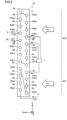
- Fig. 2 is a side view when first heat exchanger 1A is viewed from first direction A. In Fig. 2 , the gas flows from the right side to the left side with respect to first heat exchanger 1A.
- each of the plurality of fins 2 extends along second direction B and third direction C.
- the plurality of fins 2 are spaced apart from each other in first direction A.
- Each of the plurality of fins 2 is connected to each of the plurality of first heat transfer tubes 3 and the plurality of second heat transfer tubes 4.
- Each of the plurality of fins 2 is provided to form, around each of the plurality of first heat transfer tubes 3, a first air passage AF1 through which the gas flows in second direction B, and to form, around each of the plurality of second heat transfer tubes 4, a second air passage AF2 through which the gas flows in second direction B.
- each of the plurality of first heat transfer tubes 3 extends along first direction A.
- the plurality of first heat transfer tubes 3 are spaced apart from each other and arranged side by side in second direction B and third direction C.
- the plurality of first heat transfer tubes 3 include a first group of first heat transfer tubes 3a and a second group of first heat transfer tubes 3b.
- First air passage AF1 is formed around the first group of first heat transfer tubes 3a and the second group of first heat transfer tubes 3b.
- each of the plurality of second heat transfer tubes 4 extends along first direction A.
- the plurality of second heat transfer tubes 4 are spaced apart from each other and arranged side by side in second direction B and third direction C.
- the plurality of second heat transfer tubes 4 include a first group of second heat transfer tubes 4a and a second group of second heat transfer tubes 4b.
- Second air passage AF2 is formed around the first group of second heat transfer tubes 4a and the second group of second heat transfer tubes 4b.
- First air passage AF1 and second air passage AF2 are arranged side by side in third direction C.
- the gas blown by first fan 104 flows through first air passage AF1 and second air passage AF2.
- a part of the gas blown by first fan 104 flows through first air passage AF1, and the other part flows through second air passage AF2.
- a direction of an air flow flowing through first air passage AF1 is the same as a direction of an air flow flowing through second air passage AF2.
- First air passage AF1 is continuous to second air passage AF2.
- First heat transfer tubes 3a of the first group of first heat transfer tubes 3a are spaced apart from each other and arranged side by side in third direction C.
- First heat transfer tubes 3b of the second group of first heat transfer tubes 3b are spaced apart from each other and arranged side by side in third direction C.
- Each first heat transfer tube 3a of the first group of first heat transfer tubes 3a is arranged on the leeward side of first air passage AF1 relative to each first heat transfer tube 3b of the second group of first heat transfer tubes 3b in second direction B.
- Each first heat transfer tube 3b of the second group of first heat transfer tubes 3b is arranged on the windward side of first air passage AF1 relative to each first heat transfer tube 3a of the first group of first heat transfer tubes 3a in second direction B.
- Second heat transfer tubes 4a of the first group of second heat transfer tubes 4a are spaced apart from each other and arranged side by side in third direction C.
- Second heat transfer tubes 4b of the second group of second heat transfer tubes 4b are spaced apart from each other and arranged side by side in third direction C.
- Each second heat transfer tube 4a of the first group of second heat transfer tubes 4a is arranged on the leeward side of second air passage AF2 relative to each second heat transfer tube 4b of the second group of second heat transfer tubes 4b in second direction B.
- Each second heat transfer tube 4b of the second group of second heat transfer tubes 4b is arranged on the windward side of second air passage AF2 relative to each second heat transfer tube 4a of the first group of second heat transfer tubes 4a in second direction B.
- the first group of first heat transfer tubes 3a are spaced apart from and arranged side by side with the first group of second heat transfer tubes 4a in third direction C.
- the first group of first heat transfer tubes 3a are arranged below the first group of second heat transfer tubes 4a.
- the second group of first heat transfer tubes 3b are spaced apart from and arranged side by side with the second group of second heat transfer tubes 4b in third direction C.
- the second group of first heat transfer tubes 3b are arranged below the second group of second heat transfer tubes 4b.
- the first group of first heat transfer tubes 3a, the second group of first heat transfer tubes 3b, the second group of second heat transfer tubes 4b, and the first group of second heat transfer tubes 4a are connected in series in this order.
- First heat transfer tubes 3a of the first group of first heat transfer tubes 3a are connected to each other in series via connection portions 8a.
- First heat transfer tubes 3b of the second group of first heat transfer tubes 3b are connected to each other in series via connection portions 8b.
- the first group of first heat transfer tubes 3a are connected in series to the second group of first heat transfer tubes 3b via a connection portion 8c (first connection pipe).
- the first group of first heat transfer tubes 3a and the plurality of connection portions 8a form a first refrigerant flow path.
- the second group of first heat transfer tubes 3b and the plurality of connection portions 8b form a second refrigerant flow path.
- the first refrigerant flow path is connected in series to the second refrigerant flow path via connection portion 8c.
- Second heat transfer tubes 4a of the first group of second heat transfer tubes 4a are connected to each other in series via connection portions 9a.
- Second heat transfer tubes 4b of the second group of second heat transfer tubes 4b are connected to each other in series via connection portions 9b.
- the first group of second heat transfer tubes 4a are connected in series to the second group of second heat transfer tubes 4b via a connection portion 9c (second connection pipe).
- the first group of second heat transfer tubes 4a and the plurality of connection portions 9a form a third refrigerant flow path.
- the second group of second heat transfer tubes 4b and the plurality of connection portions 9b form a fourth refrigerant flow path.
- the fourth refrigerant flow path is connected in series to the third refrigerant flow path via connection portion 9c.
- the second group of first heat transfer tubes 3b are connected in series to the second group of second heat transfer tubes 4b via flow path switching portion 7.
- the second refrigerant flow path is connected in series to the fourth refrigerant flow path via flow path switching portion 7.
- a refrigerant flow path in first heat exchanger 1A is formed by connecting the first refrigerant flow path, the second refrigerant flow path, the fourth refrigerant flow path, and the third refrigerant flow path in series in this order.
- a total sum of lengths of the plurality of first heat transfer tubes 3 in first direction A is shorter than a total sum of lengths of the plurality of second heat transfer tubes 4 in first direction A.
- the lengths of first heat transfer tubes 3 in first direction A are, for example, equal to each other.
- the lengths of second heat transfer tubes 4 in first direction A are, for example, equal to each other.
- the length of each first heat transfer tube 3 in first direction A is equal to the length of each second heat transfer tube 4 in first direction A.
- the number of first heat transfer tubes 3 is smaller than the number of second heat transfer tubes 4.
- the number of the first group of first heat transfer tubes 3a is smaller than the number of the first group of second heat transfer tubes 4a.
- the number of the second group of first heat transfer tubes 3b is smaller than the number of the second group of second heat transfer tubes 4b.
- the number of the first group of first heat transfer tubes 3a is, for example, equal to the number of the second group of first heat transfer tubes 3b.
- the number of the first group of second heat transfer tubes 4a is, for example, equal to the number of the second group of second heat transfer tubes 4b.
- Each first heat transfer tube 3a of the first group of first heat transfer tubes 3a is, for example, arranged between two first heat transfer tubes 3b of the second group of first heat transfer tubes 3b that are adjacent in third direction C, when viewed from second direction B.
- Each first heat transfer tube 3b of the second group of first heat transfer tubes 3b is arranged between two first heat transfer tubes 3a of the first group of first heat transfer tubes 3a that are adjacent in third direction C, when viewed from second direction B.
- First heat transfer tube 3a of the first group of first heat transfer tubes 3a located at a lowermost position is, for example, arranged above first heat transfer tube 3b of the second group of first heat transfer tubes 3b located at a lowermost position.
- First heat transfer tube 3a of the first group of first heat transfer tubes 3a located at an uppermost position is, for example, arranged above first heat transfer tube 3b of the second group of first heat transfer tubes 3b located at an uppermost position.
- Second heat transfer tube 4a of the first group of second heat transfer tubes 4a located at a lowermost position is, for example, arranged above second heat transfer tube 4b of the second group of second heat transfer tubes 4b located at a lowermost position.
- Second heat transfer tube 4a of the first group of second heat transfer tubes 4a located at an uppermost position is, for example, arranged above second heat transfer tube 4b of the second group of second heat transfer tubes 4b located at an uppermost position.
- Second heat transfer tube 4b of the second group of second heat transfer tubes 4b located at the lowermost position is, for example, arranged above first heat transfer tube 3a of the first group of first heat transfer tubes 3a located at the uppermost position.
- Each second heat transfer tube 4a of the first group of second heat transfer tubes 4a is, for example, arranged between two second heat transfer tubes 4b of the second group of second heat transfer tubes 4b that are adjacent in third direction C, when viewed from second direction B.
- Each second heat transfer tube 4b of the second group of second heat transfer tubes 4b is, for example, arranged between two second heat transfer tubes 4a of the first group of second heat transfer tubes 4a that are adjacent in third direction C, when viewed from second direction B.
- First heat transfer tube 3a of the first group of first heat transfer tubes 3a arranged at the uppermost position is arranged between first heat transfer tube 3b of the second group of first heat transfer tubes 3b arranged at the uppermost position and second heat transfer tube 4b of the second group of second heat transfer tubes 4b arranged at the lowermost position, when viewed from second direction B.
- Second heat transfer tube 4b of the second group of second heat transfer tubes 4b arranged at the lowermost position and first heat transfer tube 3a of the first group of first heat transfer tubes 3a arranged at the uppermost position are arranged between first heat transfer tube 3b of the second group of first heat transfer tubes 3b arranged at the uppermost position and second heat transfer tube 4a of the first group of second heat transfer tubes 4a arranged at the lowermost position, when viewed from second direction B.
- Each of the plurality of first heat transfer tubes 3 is not arranged side by side with each of the plurality of second heat transfer tubes 4 in second direction B.
- Each of the first group of first heat transfer tubes 3a is not arranged windward and leeward of each of the first group of second heat transfer tubes 4a and the second group of second heat transfer tubes 4b in second direction B.
- Each of the first group of second heat transfer tubes 4a is not arranged windward and leeward of each of the first group of first heat transfer tubes 3a and the second group of first heat transfer tubes 3b in second direction B.
- first air passage AF1 and second air passage AF2 are arranged in parallel.
- the gas flowing into first air passage AF1 is first subjected to heat exchange with the refrigerant flowing through the second group of first heat transfer tubes 3b, and then, is subjected to heat exchange with the refrigerant flowing through the first group of first heat transfer tubes 3a, and then, flows out of first air passage AF1.
- the gas flowing into second air passage AF2 is first subjected to heat exchange with the refrigerant flowing through the second group of second heat transfer tubes 4b, and then, is subjected to heat exchange with the refrigerant flowing through the first group of second heat transfer tubes 4a, and then, flows out of second air passage AF2.
- the features of the plurality of first heat transfer tubes 3 and the plurality of second heat transfer tubes 4 other than the above-described features are, for example, equal to each other.
- Flow path cross-sectional areas of the plurality of first heat transfer tubes 3 and the plurality of second heat transfer tubes 4 are, for example, equal to each other.
- the first group of first heat transfer tubes 3a are, for example, equally spaced apart from each other in third direction C.
- the second group of first heat transfer tubes 3b are, for example, equally spaced apart from each other in third direction C.
- the first group of second heat transfer tubes 4a are, for example, equally spaced apart from each other in third direction C.
- the second group of second heat transfer tubes 4b are, for example, equally spaced apart from each other in third direction C.
- a distance between two first heat transfer tubes 3a that are adjacent in third direction C is, for example, equal to a distance between two first heat transfer tubes 3b that are adjacent in third direction C.
- a distance between two second heat transfer tubes 4a that are adjacent in third direction C is, for example, equal to a distance between two second heat transfer tubes 4b that are adjacent in third direction C.
- the distance between two first heat transfer tubes 3a that are adjacent in third direction C, the distance between two first heat transfer tubes 3b that are adjacent in third direction C, the distance between two second heat transfer tubes 4a that are adjacent in third direction C, the distance between two second heat transfer tubes 4b that are adjacent in third direction C, a distance between first heat transfer tube 3a and second heat transfer tube 4a that are adjacent in third direction C, and a distance between first heat transfer tube 3b and second heat transfer tube 4b that are adjacent in third direction C are, for example, equal to each other.
- the first group of first heat transfer tubes 3a and the first group of second heat transfer tubes 4a are, for example, arranged on a straight line extending along third direction C.
- the second group of first heat transfer tubes 3b and the second group of second heat transfer tubes 4b are, for example, arranged on a straight line extending along third direction C.
- a distance between the first group of first heat transfer tubes 3a and the second group of first heat transfer tubes 3b in second direction B is, for example, equal to a distance between the first group of second heat transfer tubes 4a and the second group of second heat transfer tubes 4b in second direction B.
- first flow inlet/outlet portion 5 and second flow inlet/outlet portion 6 are a portion through which the refrigerant flows into or out of the above-described refrigerant flow path of first heat exchanger 1A.
- First flow inlet/outlet portion 5 is connected to first heat transfer tube 3a of the first group of first heat transfer tubes 3a located at the lowermost position. In other words, first flow inlet/outlet portion 5 is connected to a lower end of the first refrigerant flow path.
- Second flow inlet/outlet portion 6 is connected to second heat transfer tube 4a of the first group of second heat transfer tubes 4a located at the uppermost position. In other words, second flow inlet/outlet portion 6 is connected to an upper end of the third refrigerant flow path.
- Solid line arrows shown in Fig. 2 indicate the flow direction of the refrigerant that circulates in the above-described refrigerant circuit, when refrigeration cycle apparatus 100 is in the above-described first state.
- Dotted line arrows shown in Fig. 2 indicate the flow direction of the refrigerant that circulates in the above-described refrigerant circuit, when refrigeration cycle apparatus 100 is in the above-described second state.
- First flow inlet/outlet portion 5 is connected to the above-described refrigerant circuit to function as a flow outlet portion through which the refrigerant flows out in the above-described first state, and function as a flow inlet portion through which the refrigerant flows in in the above-described second state.
- Second flow inlet/outlet portion 6 is connected to the above-described refrigerant circuit to function as a flow inlet portion through which the refrigerant flows in in the above-described first state, and function as a flow outlet portion through which the refrigerant flows out in the above-described second state.
- Flow path switching portion 7 is a portion that connects first heat transfer tube 3 corresponding to first air passage AF 1 to second heat transfer tube 4 corresponding to second air passage AF2 in series.
- First heat exchanger 1A does not necessarily need to include flow path switching portion 7.
- Each of the plurality of connection portions 8a connects one ends or the other ends in first direction A of two first heat transfer tubes 3a of the first group of first heat transfer tubes 3 that are adjacent in third direction C.
- Each of the plurality of connection portions 8b connects one ends or the other ends in first direction A of two first heat transfer tubes 3b of the second group of first heat transfer tubes 3b that are adjacent in third direction C.
- Connection portion 8c connects one ends or the other ends in first direction A of first heat transfer tube 3a of the first group of first heat transfer tubes 3a located at the uppermost position and first heat transfer tube 3b of the second group of first heat transfer tubes 3b located at the lowermost position.
- first heat transfer tube 3 a of the first group of first heat transfer tubes 3a located at the uppermost position is connected to first heat transfer tube 3a that is adjacent to that first heat transfer tube 3a in third direction C, via connection portion 8a.
- the other end in first direction A of first heat transfer tube 3a of the first group of first heat transfer tubes 3a located at the uppermost position is connected to the other end in first direction A of first heat transfer tube 3b of the second group of first heat transfer tubes 3b located at the lowermost position, via connection portion 8c.
- Each of the plurality of connection portions 9a connects one ends or the other ends in first direction A of two second heat transfer tubes 4a of the first group of second heat transfer tubes 4a that are adjacent in third direction C.
- Each of the plurality of connection portions 9b connects one ends or the other ends in first direction A of two second heat transfer tubes 4b of the second group of second heat transfer tubes 4b that are adjacent in third direction C.
- Connection portion 9c connects one ends or the other ends in first direction A of second heat transfer tube 4a of the first group of second heat transfer tubes 4a located at the lowermost position and second heat transfer tube 4b of the second group of second heat transfer tubes 4b located at the uppermost position.
- first direction A of second heat transfer tubes 4a of the first group of second heat transfer tubes 4a located at the lowermost position is connected to second heat transfer tube 4a that is adjacent to that second heat transfer tube 4a in third direction C, via connection portion 9a.
- the other end in first direction A of second heat transfer tube 4a of the first group of second heat transfer tubes 4a located at the lowermost position is connected to the other end in first direction A of second heat transfer tube 4b of the second group of second heat transfer tubes 4b located at the uppermost position, via connection portion 9c.
- connection portions 8a, 8b, 8c, 9a, 9b, and 9c indicated by dotted lines are connected to one ends of the plurality of first heat transfer tubes 3 and the plurality of second heat transfer tubes 4, and connection portions 8a, 8b, 8c, 9a, 9b, and 9c indicated by solid lines are connected to the other ends of the plurality of first heat transfer tubes 3 and the plurality of second heat transfer tubes 4.
- the upstream portion arranged on the refrigerant inflow side relative to the central portion of the refrigerant flow path when the heat exchanger functions as an evaporator is formed by alternately connecting in series the heat transfer tubes arranged on the windward side and the heat transfer tubes arranged on the leeward side.
- the two heat transfer tubes arranged to form a counter flow and the two heat transfer tubes arranged to form a parallel flow are alternately connected in series.
- first heat exchanger 1A does not include the above-described upstream portion of the above-described conventional heat exchanger.
- the plurality of first heat transfer tubes 3 of first heat exchanger 1A include the first group of first heat transfer tubes 3a arranged side by side in third direction C and connected to each other in series, and the second group of first heat transfer tubes 3b arranged side by side in third direction C and connected to each other in series.
- the first group of first heat transfer tubes 3a are connected in series to the second group of first heat transfer tubes 3b, and arranged on the leeward side of first air passage AF1 relative to the second group of first heat transfer tubes 3b in second direction B.
- the plurality of second heat transfer tubes 4 include the first group of second heat transfer tubes 4a arranged side by side in third direction C and connected to each other in series, and the second group of second heat transfer tubes 4b arranged side by side in third direction C and connected to each other in series.
- the first group of second heat transfer tubes 4a are connected in series to the second group of second heat transfer tubes 4b, and arranged on the leeward side of second air passage AF2 relative to the second group of second heat transfer tubes 4b in second direction B.
- the first group of first heat transfer tubes 3a, the second group of first heat transfer tubes 3b, the second group of second heat transfer tubes 4b, and the first group of second heat transfer tubes 4a are connected in series in this order.
- each of the plurality of first heat transfer tubes 3 is not arranged to form a parallel flow in the upstream portion (first air passage AF1) arranged on the refrigerant inflow side relative to the central portion of first heat exchanger 1A in third direction C when first heat exchanger 1A functions as an evaporator.
- first heat exchanger 1A functions as an evaporator
- a temperature of the refrigerant flowing through the second group of first heat transfer tubes 3b arranged on the windward side of first air passage AF1 is higher than a temperature of the refrigerant flowing through the first group of first heat transfer tubes 3a arranged on the leeward side.
- a temperature of the refrigerant flowing through the second group of second heat transfer tubes 4b arranged on the windward side of second air passage AF2 is even higher than a temperature of the refrigerant flowing through the second group of first heat transfer tubes 3b arranged on the windward side of first air passage AF1.
- first heat exchanger 1A frost formation is suppressed as compared with the above-described conventional heat exchanger.
- Fig. 3(a) is a graph showing temperature changes of non-azeotropic mixed refrigerant flowing through the plurality of first heat transfer tubes 3 and gas flowing through first air passage AF 1, when the non-azeotropic mixed refrigerant flows through first heat exchanger 1A that functions as an evaporator.
- Fig. 3(b) is a graph showing temperature changes of non-azeotropic mixed refrigerant flowing through the plurality of second heat transfer tubes 4 and gas flowing through second air passage AF2, when the non-azeotropic mixed refrigerant flows through first heat exchanger 1A that functions as an evaporator.
- FIG. 3(a) and 3(b) indicates a flow direction of the gas, with the right side of the horizontal axis corresponding to the windward side and the left side of the horizontal axis corresponding to the leeward side.
- the refrigerant flowing from the first refrigerant flow path to the second refrigerant flow path flows from the left side to the right side along an arrow.
- the refrigerant flowing from the fourth refrigerant flow path to the third refrigerant flow path flows from the right side to the left side along an arrow.
- the vertical axis in each of Figs. 3(a) and 3(b) indicates temperatures of the non-azeotropic mixed refrigerant and the gas.
- first heat exchanger 1A When first heat exchanger 1A functions as an evaporator, the low-temperature two-phase refrigerant decompressed by decompressing portion 103 flows into first heat exchanger 1A through first flow inlet/outlet portion 5.
- the refrigerant flows through the first refrigerant flow path, connection portion 8c, the second refrigerant flow path, flow path switching portion 7, the fourth refrigerant flow path, connection portion 9c, and the third refrigerant flow path in this order, and is subjected to heat exchange with the gas flowing through first air passage AF1, and then, is subjected to heat exchange with the gas flowing through second air passage AF2.
- a degree of dryness of the two-phase refrigerant flowing through the evaporator increases gradually from first flow inlet/outlet portion 5 toward second flow inlet/outlet portion 6.
- a temperature of the refrigerant having a high degree of dryness is higher than a temperature of the refrigerant having a low degree of dryness due to the above-described temperature gradient. Therefore, when the refrigerant is non-azeotropic mixed refrigerant, the temperature of the two-phase refrigerant flowing through the evaporator also increases gradually from first flow inlet/outlet portion 5 toward second flow inlet/outlet portion 6 due to the above-described temperature gradient.
- first heat exchanger 1A the first group of first heat transfer tubes 3a through which the refrigerant having the lowest temperature flows are arranged leeward of the second group of first heat transfer tubes 3b through which the refrigerant having a higher temperature than that of the refrigerant flowing through the first group of first heat transfer tubes 3a flows.
- first heat exchanger 1A frost formation is suppressed on the windward side of first air passage AF1.
- heat exchange with the refrigerant flowing through the second group of first heat transfer tubes 3b makes a temperature and a humidity of the gas flowing around the first group of first heat transfer tubes 3a lower than a temperature and a humidity of the gas flowing around the second group of first heat transfer tubes 3b.
- heat exchange is performed between the refrigerant having a comparatively low temperature and the gas having a comparatively low temperature. Therefore, in first heat exchanger 1A, frost formation is suppressed on the leeward side of first air passage AF1.
- a temperature of the non-azeotropic mixed refrigerant flowing through the second group of second heat transfer tubes 4b is higher than a temperature of the non-azeotropic mixed refrigerant flowing through the second group of first heat transfer tubes 3b.
- first heat exchanger 1A when first heat exchanger 1A functions as an evaporator, first heat exchanger 1A has high heat exchange performance while suppressing frost formation.
- first heat exchanger 1A When first heat exchanger 1A functions as a condenser, the refrigerant having a high temperature and a high degree of dryness, which is discharged from compressor 101, flows into first heat exchanger 1A through second flow inlet/outlet portion 6.
- the refrigerant flows through the third refrigerant flow path, connection portion 9c, the fourth refrigerant flow path, flow path switching portion 7, the second refrigerant flow path, connection portion 8c, and the first refrigerant flow path in this order, and is subjected to heat exchange with the gas flowing through second air passage AF2, and then, is subjected to heat exchange with the gas flowing through first air passage AF1.
- the degree of dryness of the refrigerant decreases gradually.
- the above-described temperature gradient makes a temperature of the refrigerant having a high degree of dryness higher than a temperature of the refrigerant having a low degree of dryness.
- Fig. 4(a) is a graph showing temperature changes of the non-azeotropic mixed refrigerant flowing through the plurality of second heat transfer tubes 4 and the gas flowing through second air passage AF2, when the non-azeotropic mixed refrigerant flows through first heat exchanger 1A that functions as a condenser.
- Fig. 4(b) is a graph showing temperature changes of the non-azeotropic mixed refrigerant flowing through the plurality of first heat transfer tubes 3 and the gas flowing through first air passage AF1, when the non-azeotropic mixed refrigerant flows through first heat exchanger 1A that functions as a condenser.
- FIG. 4(a) and 4(b) indicates a flow direction of the gas, with the right side of the horizontal axis corresponding to the windward side and the left side of the horizontal axis corresponding to the leeward side.
- the vertical axis in each of Figs. 4(a) and 4(b) indicates temperatures of the non-azeotropic mixed refrigerant and the gas.
- the gas flowing through second air passage AF2 is first subjected to heat exchange with the refrigerant flowing through the second group of second heat transfer tubes 4b, and then, is subjected to heat exchange with the refrigerant flowing through the first group of second heat transfer tubes 4a. Therefore, a temperature of the gas flowing around the second group of second heat transfer tubes 4b becomes lower than a temperature of the gas flowing around the first group of second heat transfer tubes 4a.
- the above-described temperature gradient makes a temperature of the non-azeotropic mixed refrigerant flowing through the second group of second heat transfer tubes 4b lower than a temperature of the non-azeotropic mixed refrigerant flowing through the first group of second heat transfer tubes 4a.
- the temperature of the non-azeotropic mixed refrigerant flowing through the second group of second heat transfer tubes 4b is sufficiently higher than the temperature of the gas flowing around the second group of second heat transfer tubes 4b.
- second air passage AF2 a temperature difference between the comparatively-low-temperature non-azeotropic mixed refrigerant flowing through the second group of second heat transfer tubes 4b and the comparatively-low-temperature gas flowing toward the second group of second heat transfer tubes 4b, and a temperature difference between the comparatively-high-temperature non-azeotropic mixed refrigerant flowing through the first group of second heat transfer tubes 4a and the comparatively-high-temperature gas flowing toward the first group of second heat transfer tubes 4a are both sufficiently large. Therefore, the heat exchange performance of first heat exchanger 1A is equal to or higher than the heat exchange performance of the above-described conventional heat exchanger.
- First air passage AF 1 and the first group of first heat transfer tubes 3a and the second group of first heat transfer tubes 3b arranged in first air passage AF 1 function as a supercooling region that supercools the refrigerant whose degree of dryness is sufficiently decreased by flowing through the first group of second heat transfer tubes 4a and the second group of second heat transfer tubes 4b arranged in second air passage AF2.
- a region of the plurality of first heat transfer tubes 3 that functions as a supercooling region increases.
- the heat exchange performance required for first air passage AF 1, the first group of first heat transfer tubes 3a and the second group of first heat transfer tubes 3b is lower than the heat exchange performance required for second air passage AF2, the first group of second heat transfer tubes 4a and the second group of second heat transfer tubes 4b.
- a degree of influence of the heat exchange performance of first air passage AF 1, the first group of first heat transfer tubes 3a and the second group of first heat transfer tubes 3b on the heat exchange performance of first heat exchanger 1A is lower than a degree of influence of the heat exchange performance of second air passage AF2, the first group of second heat transfer tubes 4a and the second group of second heat transfer tubes 4b on the heat exchange performance of first heat exchanger 1A. Therefore, the heat exchange performance of first heat exchanger 1A is not impaired by the heat exchange performance of first air passage AF1, the first group of first heat transfer tubes 3a and the second group of first heat transfer tubes 3b.
- First heat exchanger 1A further includes first flow inlet/outlet portion 5 which is connected to the lower end of the first refrigerant flow path and through which the refrigerant flows in or out, connection portion 8c that connects the upper end of the first refrigerant flow path to the lower end of the second refrigerant flow path, and connection portion 9c that connects the upper end of the second refrigerant flow path to the lower end of the third refrigerant flow path.
- first heat exchanger 1A when first heat exchanger 1A functions as a condenser, the refrigerant flows through each of the first group of first heat transfer tubes 3a, the second group of first heat transfer tubes 3b, the second group of second heat transfer tubes 4b, and the first group of second heat transfer tubes 4a from bottom to top.
- the flow direction of the refrigerant flowing through the first group of first heat transfer tubes 3a and the flow direction of the refrigerant flowing through the second group of first heat transfer tubes 3b are the same.
- unevenness between a temperature difference of the refrigerant flowing through one set of first heat transfer tube 3a and first heat transfer tube 3b arranged side by side in second direction B, and a temperature difference of the refrigerant flowing through another set of first heat transfer tube 3a and first heat transfer tube 3b arranged side by side with the one set in third direction C is smaller as compared with when the flow direction of the refrigerant flowing through the first group of first heat transfer tubes 3a and the flow direction of the refrigerant flowing through the second group of first heat transfer tubes 3b are opposite. Therefore, high heat exchange performance can be maintained in each of the one set of first heat transfer tube 3a and first heat transfer tube 3b arranged side by side in second direction B.
- Refrigeration cycle apparatus 100 includes first heat exchanger 1A.
- frost formation is suppressed in first heat exchanger 1A. Therefore, when refrigeration cycle apparatus 100 and a refrigeration cycle apparatus including the above-described conventional heat exchanger are used under the same condition, the number of times of defrosting operation per use time of is smaller in the former than in the latter. As a result, refrigeration cycle apparatus 100 achieves higher heat exchange performance and higher comfortability as compared with the conventional refrigeration cycle apparatus.
- a first heat exchanger 1B according to a second embodiment is configured basically similarly to first heat exchanger 1A according to the first embodiment.
- first heat exchanger 1B according to the second embodiment is different from first heat exchanger 1A according to the first embodiment in that the plurality of second heat transfer tubes 4 further include a third group of second heat transfer tubes 4c and a fourth group of second heat transfer tubes 4d.
- the third group of second heat transfer tubes 4c are arranged side by side in third direction C and connected to each other in series.
- the fourth group of second heat transfer tubes 4d are arranged side by side in the third direction and connected to each other in series.
- the third group of second heat transfer tubes 4c are connected in series to the fourth group of second heat transfer tubes 4d, and arranged on the leeward side of second air passage AF2 relative to the fourth group of second heat transfer tubes 4d in second direction B.
- the third group of second heat transfer tubes 4c and the fourth group of second heat transfer tubes 4d are connected in parallel to the first group of second heat transfer tubes 4a and the second group of second heat transfer tubes 4b.
- Each second heat transfer tube 4c of the third group of second heat transfer tubes 4c is arranged on the leeward side of second air passage AF2 relative to each second heat transfer tube 4d of the fourth group of second heat transfer tubes 4d in second direction B.
- Each second heat transfer tube 4d of the fourth group of second heat transfer tubes 4d is arranged on the windward side of second air passage AF2 relative to each second heat transfer tube 4c of the third group of second heat transfer tubes 4c in second direction B.
- the third group of second heat transfer tubes 4c are spaced apart from and arranged side by side with the first group of second heat transfer tubes 4a in third direction C, and are spaced apart from the first group of first heat transfer tubes 3a in third direction C.
- the third group of second heat transfer tubes 4c are arranged below the first group of second heat transfer tubes 4a and arranged above the first group of first heat transfer tubes 3 a.
- the fourth group of second heat transfer tubes 4d are spaced apart from and arranged side by side with the second group of second heat transfer tubes 4b in third direction C, and are spaced apart from the second group of first heat transfer tubes 3b in third direction C.
- the fourth group of second heat transfer tubes 4d are arranged below the second group of second heat transfer tubes 4b and arranged above the second group of first heat transfer tubes 3b.
- first heat exchanger 1B the first group of first heat transfer tubes 3a, the second group of first heat transfer tubes 3b, the second group of second heat transfer tubes 4b, and the first group of second heat transfer tubes 4a are connected in series in this order, and the first group of first heat transfer tubes 3a, the second group of first heat transfer tubes 3b, the fourth group of second heat transfer tubes 4d, and the third group of second heat transfer tubes 4c are connected in series in this order.
- Second heat transfer tubes 4c of the third group of second heat transfer tubes 4c are connected to each other in series via connection portions 9d.
- Second heat transfer tubes 4d of the fourth group of second heat transfer tubes 4d are connected to each other in series via connection portions 9e.
- the third group of second heat transfer tubes 4c are connected in series to the fourth group of second heat transfer tubes 4d via a connection portion 9f.
- the third group of second heat transfer tubes 4c and the plurality of connection portions 9d form a fifth refrigerant flow path.
- the fourth group of second heat transfer tubes 4d and the plurality of connection portions 9e form a sixth refrigerant flow path.
- the fifth refrigerant flow path is connected in series to the sixth refrigerant flow path via connection portion 9f.
- first heat exchanger 1B further includes a third flow inlet/outlet portion 10.
- Third flow inlet/outlet portion 10 is a portion through which the refrigerant flows into or out of the above-described refrigerant flow path of first heat exchanger 1B.
- Third flow inlet/outlet portion 10 is connected to second heat transfer tube 4c of the third group of second heat transfer tubes 4c located at an uppermost position. In other words, third flow inlet/outlet portion 10 is connected to an upper end of the fifth refrigerant flow path.
- connection portion 9c (second connection pipe) connects one ends or the other ends in first direction A of second heat transfer tube 4a of the first group of second heat transfer tubes 4a located at an uppermost position and second heat transfer tube 4b of the second group of second heat transfer tubes 4b located at an uppermost position.
- the second group of first heat transfer tubes 3b are connected in series to the fourth group of second heat transfer tubes 4d via flow path switching portion 7.
- the second refrigerant flow path is connected in series to the sixth refrigerant flow path via flow path switching portion 7.
- first heat exchanger 1B a refrigerant flow path in which the first refrigerant flow path, the second refrigerant flow path, the fourth refrigerant flow path, and the third refrigerant flow path are connected in series in this order, and a refrigerant flow path in which the first refrigerant flow path, the second refrigerant flow path, the sixth refrigerant flow path, and the fifth refrigerant flow path are connected in series in this order are formed.
- a total sum of flow path cross-sectional areas of the plurality of second heat transfer tubes 4 is larger than a total sum of flow path cross-sectional areas of the plurality of first heat transfer tubes 3.
- the total sum of the flow path cross-sectional areas refers to a total sum of flow path cross-sectional areas of the plurality of first heat transfer tubes 3 and the plurality of second heat transfer tubes 4 that are seen in an arbitrary one cross section orthogonal to first direction A.
- the features of the plurality of first heat transfer tubes 3 and the plurality of second heat transfer tubes 4 other than the above-described features are, for example, equal to each other.
- the flow path cross-sectional areas of the plurality of first heat transfer tubes 3 and the plurality of second heat transfer tubes 4 are, for example, equal to each other.
- the number of the third group of second heat transfer tubes 4c is, for example, equal to the number of the first group of second heat transfer tubes 4a.
- the number of the fourth group of second heat transfer tubes 4d is, for example, equal to the number of the second group of second heat transfer tubes 4b.
- first heat exchanger 1B according to the second embodiment is configured similarly to first heat exchanger 1A according to the first embodiment, first heat exchanger 1B according to the second embodiment can produce an effect similar to that of first heat exchanger 1A.
- first heat exchanger 1A When first heat exchanger 1A functions as an evaporator, the degree of dryness of the refrigerant flowing through the plurality of second heat transfer tubes 4 is higher than the degree of dryness of the refrigerant flowing through the plurality of first heat transfer tubes 3 as described above. Therefore, when the total sum of the flow path cross-sectional areas of the plurality of second heat transfer tubes 4 is, for example, equal to the total sum of the flow path cross-sectional areas of the plurality of first heat transfer tubes 3, a flow rate of the refrigerant flowing through the plurality of second heat transfer tubes 4 is higher than a flow rate of the refrigerant flowing through the plurality of first heat transfer tubes 3. In this case, a pressure loss of the refrigerant flowing through the plurality of second heat transfer tubes 4 is higher than a pressure loss of the refrigerant flowing through the plurality of first heat transfer tubes 3.
- first heat exchanger 1B the third group of second heat transfer tubes 4c and the fourth group of second heat transfer tubes 4d are connected in series to the first group of first heat transfer tubes 3a and the second group of first heat transfer tubes 3b, and are connected in parallel to the first group of second heat transfer tubes 4a and the second group of second heat transfer tubes 4b.
- the total sum of the flow path cross-sectional areas of the plurality of second heat transfer tubes 4 is larger than the total sum of the flow path cross-sectional areas of the plurality of first heat transfer tubes 3.
- a flow rate of the refrigerant flowing through the plurality of second heat transfer tubes 4 is lower than that when the total sum of the flow path cross-sectional areas of the plurality of second heat transfer tubes 4 is equal to the total sum of the flow path cross-sectional areas of the plurality of first heat transfer tubes 3.
- the plurality of first heat transfer tubes 3 may be configured differently from the plurality of second heat transfer tubes 4.
- the flow path cross-sectional areas of the plurality of first heat transfer tubes 3 may be smaller than the flow path cross-sectional areas of the plurality of second heat transfer tubes 4.
- connection portion 9c may connect one ends or the other ends in first direction A of second heat transfer tube 4a of the first group of second heat transfer tubes 4a located at a lowermost position and second heat transfer tube 4b of the second group of second heat transfer tubes 4b located at the uppermost position, similarly to first heat exchanger 1A.
- connection portion 9f may connect one ends or the other ends in first direction A of second heat transfer tube 4c of the third group of second heat transfer tubes 4c located at a lowermost position and second heat transfer tube 4d of the fourth group of second heat transfer tubes 4d located at an uppermost position.
- 1A, 1B first heat exchanger 2 fin; 3, 3a, 3b first heat transfer tube; 4, 4a, 4b, 4c, 4d second heat transfer tube; 5 first flow inlet/outlet portion; 6 second flow inlet/outlet portion; 7 path switching portion; 8, 8a, 8b, 8c, 9a, 9b, 9c, 9d, 9e, 9f connection portion; 10 third flow inlet/outlet portion; 11 second heat exchanger; 100 refrigeration cycle apparatus; 101 compressor; 102 four-way valve; 103 decompressing portion; 104 first fan.
Landscapes
- Engineering & Computer Science (AREA)
- Physics & Mathematics (AREA)
- Thermal Sciences (AREA)
- Mechanical Engineering (AREA)
- General Engineering & Computer Science (AREA)
- Geometry (AREA)
- Heat-Exchange Devices With Radiators And Conduit Assemblies (AREA)
Description
- The present invention relates to a heat exchanger and a refrigeration cycle apparatus.
- Non-azeotropic mixed refrigerant is a mixture of refrigerant having a high boiling point and refrigerant having a low boiling point. Therefore, in the non-azeotropic mixed refrigerant, a saturation temperature varies depending on a degree of dryness, because the refrigerant having a low boiling point is gasified in a region where the degree of dryness is low, and the refrigerant having a high boiling point is gasified in a region where the degree of dryness is high. As a result, unlike single refrigerant, in the non-azeotropic mixed refrigerant, a saturation gas temperature at the same pressure is higher than a saturation liquid temperature. That is, in a Mollier diagram (p-h diagram), an isothermal line of the non-azeotropic mixed refrigerant has a gradient in a two-phase region (hereinafter, referred to as "temperature gradient").
- On the refrigerant flow inlet side of an evaporator of a refrigeration cycle apparatus, heat exchange is performed between two-phase refrigerant having a relatively low temperature and gas (e.g., outdoor air) having a higher temperature than that of the refrigerant, to thereby raise a degree of dryness of the two-phase refrigerant. When the refrigerant circulating in the refrigeration cycle apparatus is non-azeotropic mixed refrigerant, an influence of the above-described temperature gradient makes a saturation temperature of the non-azeotropic mixed refrigerant on the refrigerant flow outlet side of the evaporator higher than a saturation temperature of the non-azeotropic mixed refrigerant on the refrigerant flow inlet side of the evaporator. This makes a temperature difference between the non-azeotropic mixed refrigerant and the gas flowing on the refrigerant flow outlet side of the evaporator smaller than a temperature difference between the non-azeotropic mixed refrigerant and the outdoor air flowing on the refrigerant flow inlet side of the evaporator, and thus, an amount of heat exchange on the refrigerant flow outlet side of the evaporator becomes smaller than an amount of heat exchange on the refrigerant flow inlet side of the evaporator.
- Examples of a method for enhancing heat exchange performance of an evaporator include causing a flow direction of refrigerant and a flow direction of outdoor air to form a so-called counter flow. However, in a refrigeration cycle apparatus in which switching between a second state in which the flow direction of the refrigerant is inverted and a heat exchanger functions as a condenser and a first state in which the heat exchanger functions as an evaporator is performed by, for example, a four-way valve or the like, a so-called parallel flow is formed in the condenser in the second state when a counter flow is achieved in the evaporator in the first state, which leads to degradation in heat exchange performance of the condenser.
-
Japanese Patent Laying-Open No. 58-62469 - Document
JP H07 98162 A - Document
US 5 542 271 A describes an air-conditioner of a heat pump type that includes a refrigeration cycle with an interior heat exchanger, an exterior heat exchanger, a compressor, a four-way valve, and an expansion mechanism. A non-azeotrope refrigerant composed of not less than two kinds of refrigerants is used as a working medium. A refrigerant path in each of the interior and exterior heat exchangers is divided into a group of first refrigerant passages located at a region where a proportion of the liquid-phase refrigerant is large and a group of second refrigerant passages located at a region where a proportion of the liquid-phase refrigerant is small. At least part of the group of first refrigerant passages of each of the interior and exterior heat exchangers is located at the windward side. Heat transfer tubes of the group of first refrigerant passages of each of the interior and exterior heat exchangers are smaller in flow-passage cross-sectional area than those of the corresponding group of second refrigerant passages. - Document
JP 2015 141009 A -
- PTL 1:
Japanese Patent Laying-Open No. 58-62469 - PTL2: Document
JP H07 98162 A - PTL3: Document
US 5 542 271 A - PTL4: Document
JP 2015 141009 A - However, in the heat exchanger described in
Japanese Patent Laying-Open No. 58-62469 - As a result, in the above-described heat exchanger, the refrigerant having a low temperature flows through the heat transfer tube located on the relatively windward side in the above-described refrigerant flow path, and thus, frost formation is likely to occur around this heat transfer tube. As a result, in a refrigeration cycle apparatus including the above-described heat exchanger, the number of times of defrosting operation is comparatively large, which makes it difficult to sufficiently enhance heat exchange performance and comfortability.
- A main object of the present invention is to provide a heat exchanger in which even when the heat exchanger is used in a refrigeration cycle apparatus in which non-azeotropic mixed refrigerant circulates, frost formation is suppressed and degradation in heat exchange performance in each of the above-described second state and the above-described first state is suppressed, as compared with the above-described conventional heat exchanger, and to provide a refrigeration cycle apparatus including such a heat exchanger.
- A heat exchanger according to the present invention is a heat exchanger that exchanges heat between refrigerant flowing in a first direction and gas flowing in a second direction crossing the first direction, the heat exchanger including: a plurality of first heat transfer tubes and a plurality of second heat transfer tubes which extend along the first direction and through which the refrigerant flows; and at least one fin connected with each of the plurality of first heat transfer tubes and the plurality of second heat transfer tubes, and provided to form, around each of the plurality of first heat transfer tubes and the plurality of second heat transfer tubes, an air passage in which the gas flows in the second direction. The plurality of first heat transfer tubes include a first group of first heat transfer tubes arranged side by side in a third direction and connected to each other in series, and a second group of first heat transfer tubes arranged side by side in the third direction and connected to each other in series. The first group of first heat transfer tubes are connected in series to the second group of first heat transfer tubes, and arranged leeward of the second group of first heat transfer tubes in the second direction. The plurality of second heat transfer tubes include a first group of second heat transfer tubes arranged side by side in the third direction and connected to each other in series, and a second group of second heat transfer tubes arranged side by side in the third direction and connected to each other in series. The first group of second heat transfer tubes are connected in series to the second group of second heat transfer tubes, and arranged leeward of the second group of second heat transfer tubes in the second direction. The first group of first heat transfer tubes, the second group of first heat transfer tubes, the second group of second heat transfer tubes, and the first group of second heat transfer tubes are connected in series in this order. A total sum of lengths of the plurality of first heat transfer tubes in the first direction is shorter than a total sum of lengths of the plurality of second heat transfer tubes in the first direction.
- According to the present invention, there can be provided a heat exchanger in which even when the heat exchanger is used in a refrigeration cycle apparatus in which non-azeotropic mixed refrigerant circulates, frost formation is suppressed and degradation in heat exchange performance in each of the above-described second state and the above-described first state is suppressed, as compared with the above-described conventional heat exchanger, and there can be provided a refrigeration cycle apparatus including such a heat exchanger.
-
-
Fig. 1 shows a refrigeration cycle apparatus according to a first embodiment. -
Fig. 2 is a side view showing arrangement of a plurality of heat transfer tubes of a heat exchanger according to the first embodiment. -
Fig. 3(a) is a graph showing temperature changes of non-azeotropic mixed refrigerant and air that are subjected to heat exchange in a first air passage of the heat exchanger when the heat exchanger according to the first embodiment functions as an evaporator, andFig. 3(b) is a graph showing temperature changes of the non-azeotropic mixed refrigerant and the air that are subjected to heat exchange in a second air passage of the heat exchanger when the heat exchanger according to the first embodiment functions as an evaporator. -
Fig. 4(a) is a graph showing temperature changes of the non-azeotropic mixed refrigerant and the air that are subjected to heat exchange in the second air passage of the heat exchanger when the heat exchanger according to the first embodiment functions as a condenser, andFig. 4(b) is a graph showing temperature changes of the non-azeotropic mixed refrigerant and the air that are subjected to heat exchange in the first air passage of the heat exchanger when the heat exchanger according to the first embodiment functions as a condenser. -
Fig. 5 is a side view showing arrangement of a plurality of heat transfer tubes of a heat exchanger according to a second embodiment. - Embodiments of the present invention will be described hereinafter with reference to the drawings, in which the same or corresponding portions are denoted by the same reference characters and description thereof will not be repeated in principle.
- As shown in
Fig. 1 , arefrigeration cycle apparatus 100 according to a first embodiment includes a refrigerant circuit in which refrigerant circulates. The refrigerant circuit includes acompressor 101, a four-way valve 102 serving as a flow path switching portion, adecompressing portion 103, afirst heat exchanger 1A, and asecond heat exchanger 11.Refrigeration cycle apparatus 100 further includes afirst fan 104 that blows air tofirst heat exchanger 1A, and asecond fan 105 that blows air tosecond heat exchanger 11.Refrigeration cycle apparatus 100 is, for example, an air conditioner.First heat exchanger 1A is, for example, an outdoor heat exchanger.Second heat exchanger 11 is, for example, an indoor heat exchanger. -
Compressor 101 has a discharge port through which the refrigerant is discharged, and a suction port through which the refrigerant is suctioned. Decompressingportion 103 is, for example, an expansion valve. Decompressingportion 103 is connected to a first flow inlet/outlet portion 5 offirst heat exchanger 1A.First fan 104 forms, onfirst heat exchanger 1A, an air flow along a below-described second direction B. - Four-
way valve 102 has a first port connected to the discharge port ofcompressor 101 via a discharge pipe, a second port connected to the suction port ofcompressor 101 via a suction pipe, a third port connected to a second flow inlet/outlet portion 6 offirst heat exchanger 1A, and a fourth port connected tosecond heat exchanger 11. Four-way valve 102 is provided to perform switching between a first state in whichsecond heat exchanger 11 functions as a condenser andfirst heat exchanger 1A functions as an evaporator, and a second state in whichfirst heat exchanger 1A functions as a condenser andsecond heat exchanger 11 functions as an evaporator. Whenrefrigeration cycle apparatus 100 is an air conditioner, the first state is achieved at the time of heating operation, and the second state is achieved at the time of cooling operation. In the first state and the second state, a direction of the air flow formed onfirst heat exchanger 1A byfirst fan 104 is constant. - Solid line arrows shown in
Fig. 1 indicate a flow direction of the refrigerant that circulates in the above-described refrigerant circuit, whenrefrigeration cycle apparatus 100 is in the above-described first state. Dotted line arrows shown inFig. 1 indicate a flow direction of the refrigerant that circulates in the above-described refrigerant circuit, whenrefrigeration cycle apparatus 100 is in the above-described second state. - As shown in
Fig. 2 ,first heat exchanger 1A mainly includes, for example, a plurality offins 2, a plurality of firstheat transfer tubes 3, a plurality of secondheat transfer tubes 4, first flow inlet/outlet portion 5, second flow inlet/outlet portion 6, a flowpath switching portion 7, and a plurality of connection portions 8 and 9.First heat exchanger 1A is provided to exchange heat between the refrigerant flowing through each of the plurality of firstheat transfer tubes 3 and the plurality of secondheat transfer tubes 4 along a first direction A and gas (e.g., outdoor air) flowing along the plurality offins 2 along second direction B. - First direction A is a direction that crosses second direction B, e.g., is orthogonal to second direction B. First direction A and second direction B are, for example, horizontal directions. A third direction C that crosses first direction A and second direction B is, for example, a vertical direction.
Fig. 2 is a side view whenfirst heat exchanger 1A is viewed from first direction A. InFig. 2 , the gas flows from the right side to the left side with respect tofirst heat exchanger 1A. - As shown in
Fig. 2 , each of the plurality offins 2 extends along second direction B and third direction C. The plurality offins 2 are spaced apart from each other in first direction A. Each of the plurality offins 2 is connected to each of the plurality of firstheat transfer tubes 3 and the plurality of secondheat transfer tubes 4. Each of the plurality offins 2 is provided to form, around each of the plurality of firstheat transfer tubes 3, a first air passage AF1 through which the gas flows in second direction B, and to form, around each of the plurality of secondheat transfer tubes 4, a second air passage AF2 through which the gas flows in second direction B. - As shown in
Fig. 2 , each of the plurality of firstheat transfer tubes 3 extends along first direction A. The plurality of firstheat transfer tubes 3 are spaced apart from each other and arranged side by side in second direction B and third direction C. The plurality of firstheat transfer tubes 3 include a first group of firstheat transfer tubes 3a and a second group of firstheat transfer tubes 3b. First air passage AF1 is formed around the first group of firstheat transfer tubes 3a and the second group of firstheat transfer tubes 3b. - As shown in
Fig. 2 , each of the plurality of secondheat transfer tubes 4 extends along first direction A. The plurality of secondheat transfer tubes 4 are spaced apart from each other and arranged side by side in second direction B and third direction C. The plurality of secondheat transfer tubes 4 include a first group of secondheat transfer tubes 4a and a second group of secondheat transfer tubes 4b. Second air passage AF2 is formed around the first group of secondheat transfer tubes 4a and the second group of secondheat transfer tubes 4b. - First air passage AF1 and second air passage AF2 are arranged side by side in third direction C. The gas blown by
first fan 104 flows through first air passage AF1 and second air passage AF2. A part of the gas blown byfirst fan 104 flows through first air passage AF1, and the other part flows through second air passage AF2. A direction of an air flow flowing through first air passage AF1 is the same as a direction of an air flow flowing through second air passage AF2. First air passage AF1 is continuous to second air passage AF2. - First
heat transfer tubes 3a of the first group of firstheat transfer tubes 3a are spaced apart from each other and arranged side by side in third direction C. Firstheat transfer tubes 3b of the second group of firstheat transfer tubes 3b are spaced apart from each other and arranged side by side in third direction C. Each firstheat transfer tube 3a of the first group of firstheat transfer tubes 3a is arranged on the leeward side of first air passage AF1 relative to each firstheat transfer tube 3b of the second group of firstheat transfer tubes 3b in second direction B. Each firstheat transfer tube 3b of the second group of firstheat transfer tubes 3b is arranged on the windward side of first air passage AF1 relative to each firstheat transfer tube 3a of the first group of firstheat transfer tubes 3a in second direction B. - Second
heat transfer tubes 4a of the first group of secondheat transfer tubes 4a are spaced apart from each other and arranged side by side in third direction C. Secondheat transfer tubes 4b of the second group of secondheat transfer tubes 4b are spaced apart from each other and arranged side by side in third direction C. Each secondheat transfer tube 4a of the first group of secondheat transfer tubes 4a is arranged on the leeward side of second air passage AF2 relative to each secondheat transfer tube 4b of the second group of secondheat transfer tubes 4b in second direction B. Each secondheat transfer tube 4b of the second group of secondheat transfer tubes 4b is arranged on the windward side of second air passage AF2 relative to each secondheat transfer tube 4a of the first group of secondheat transfer tubes 4a in second direction B. - The first group of first
heat transfer tubes 3a are spaced apart from and arranged side by side with the first group of secondheat transfer tubes 4a in third direction C. The first group of firstheat transfer tubes 3a are arranged below the first group of secondheat transfer tubes 4a. - The second group of first
heat transfer tubes 3b are spaced apart from and arranged side by side with the second group of secondheat transfer tubes 4b in third direction C. The second group of firstheat transfer tubes 3b are arranged below the second group of secondheat transfer tubes 4b. - The first group of first
heat transfer tubes 3a, the second group of firstheat transfer tubes 3b, the second group of secondheat transfer tubes 4b, and the first group of secondheat transfer tubes 4a are connected in series in this order. - First
heat transfer tubes 3a of the first group of firstheat transfer tubes 3a are connected to each other in series viaconnection portions 8a. Firstheat transfer tubes 3b of the second group of firstheat transfer tubes 3b are connected to each other in series viaconnection portions 8b. The first group of firstheat transfer tubes 3a are connected in series to the second group of firstheat transfer tubes 3b via aconnection portion 8c (first connection pipe). The first group of firstheat transfer tubes 3a and the plurality ofconnection portions 8a form a first refrigerant flow path. The second group of firstheat transfer tubes 3b and the plurality ofconnection portions 8b form a second refrigerant flow path. The first refrigerant flow path is connected in series to the second refrigerant flow path viaconnection portion 8c. - Second
heat transfer tubes 4a of the first group of secondheat transfer tubes 4a are connected to each other in series viaconnection portions 9a. Secondheat transfer tubes 4b of the second group of secondheat transfer tubes 4b are connected to each other in series viaconnection portions 9b. The first group of secondheat transfer tubes 4a are connected in series to the second group of secondheat transfer tubes 4b via aconnection portion 9c (second connection pipe). The first group of secondheat transfer tubes 4a and the plurality ofconnection portions 9a form a third refrigerant flow path. The second group of secondheat transfer tubes 4b and the plurality ofconnection portions 9b form a fourth refrigerant flow path. The fourth refrigerant flow path is connected in series to the third refrigerant flow path viaconnection portion 9c. - The second group of first
heat transfer tubes 3b are connected in series to the second group of secondheat transfer tubes 4b via flowpath switching portion 7. The second refrigerant flow path is connected in series to the fourth refrigerant flow path via flowpath switching portion 7. - As described above, a refrigerant flow path in
first heat exchanger 1A is formed by connecting the first refrigerant flow path, the second refrigerant flow path, the fourth refrigerant flow path, and the third refrigerant flow path in series in this order. - In accordance with the invention, a total sum of lengths of the plurality of first
heat transfer tubes 3 in first direction A is shorter than a total sum of lengths of the plurality of secondheat transfer tubes 4 in first direction A. The lengths of firstheat transfer tubes 3 in first direction A are, for example, equal to each other. The lengths of secondheat transfer tubes 4 in first direction A are, for example, equal to each other. The length of each firstheat transfer tube 3 in first direction A is equal to the length of each secondheat transfer tube 4 in first direction A. Preferably, the number of firstheat transfer tubes 3 is smaller than the number of secondheat transfer tubes 4. The number of the first group of firstheat transfer tubes 3a is smaller than the number of the first group of secondheat transfer tubes 4a. The number of the second group of firstheat transfer tubes 3b is smaller than the number of the second group of secondheat transfer tubes 4b. The number of the first group of firstheat transfer tubes 3a is, for example, equal to the number of the second group of firstheat transfer tubes 3b. The number of the first group of secondheat transfer tubes 4a is, for example, equal to the number of the second group of secondheat transfer tubes 4b. - Each first
heat transfer tube 3a of the first group of firstheat transfer tubes 3a is, for example, arranged between two firstheat transfer tubes 3b of the second group of firstheat transfer tubes 3b that are adjacent in third direction C, when viewed from second direction B. Each firstheat transfer tube 3b of the second group of firstheat transfer tubes 3b is arranged between two firstheat transfer tubes 3a of the first group of firstheat transfer tubes 3a that are adjacent in third direction C, when viewed from second direction B. - First
heat transfer tube 3a of the first group of firstheat transfer tubes 3a located at a lowermost position is, for example, arranged above firstheat transfer tube 3b of the second group of firstheat transfer tubes 3b located at a lowermost position. Firstheat transfer tube 3a of the first group of firstheat transfer tubes 3a located at an uppermost position is, for example, arranged above firstheat transfer tube 3b of the second group of firstheat transfer tubes 3b located at an uppermost position. - Second
heat transfer tube 4a of the first group of secondheat transfer tubes 4a located at a lowermost position is, for example, arranged above secondheat transfer tube 4b of the second group of secondheat transfer tubes 4b located at a lowermost position. Secondheat transfer tube 4a of the first group of secondheat transfer tubes 4a located at an uppermost position is, for example, arranged above secondheat transfer tube 4b of the second group of secondheat transfer tubes 4b located at an uppermost position. Secondheat transfer tube 4b of the second group of secondheat transfer tubes 4b located at the lowermost position is, for example, arranged above firstheat transfer tube 3a of the first group of firstheat transfer tubes 3a located at the uppermost position. - Each second
heat transfer tube 4a of the first group of secondheat transfer tubes 4a is, for example, arranged between two secondheat transfer tubes 4b of the second group of secondheat transfer tubes 4b that are adjacent in third direction C, when viewed from second direction B. Each secondheat transfer tube 4b of the second group of secondheat transfer tubes 4b is, for example, arranged between two secondheat transfer tubes 4a of the first group of secondheat transfer tubes 4a that are adjacent in third direction C, when viewed from second direction B. - First
heat transfer tube 3a of the first group of firstheat transfer tubes 3a arranged at the uppermost position is arranged between firstheat transfer tube 3b of the second group of firstheat transfer tubes 3b arranged at the uppermost position and secondheat transfer tube 4b of the second group of secondheat transfer tubes 4b arranged at the lowermost position, when viewed from second direction B. - Second
heat transfer tube 4b of the second group of secondheat transfer tubes 4b arranged at the lowermost position and firstheat transfer tube 3a of the first group of firstheat transfer tubes 3a arranged at the uppermost position are arranged between firstheat transfer tube 3b of the second group of firstheat transfer tubes 3b arranged at the uppermost position and secondheat transfer tube 4a of the first group of secondheat transfer tubes 4a arranged at the lowermost position, when viewed from second direction B. - Each of the plurality of first
heat transfer tubes 3 is not arranged side by side with each of the plurality of secondheat transfer tubes 4 in second direction B. Each of the first group of firstheat transfer tubes 3a is not arranged windward and leeward of each of the first group of secondheat transfer tubes 4a and the second group of secondheat transfer tubes 4b in second direction B. Each of the first group of secondheat transfer tubes 4a is not arranged windward and leeward of each of the first group of firstheat transfer tubes 3a and the second group of firstheat transfer tubes 3b in second direction B. - In other words, first air passage AF1 and second air passage AF2 are arranged in parallel. The gas flowing into first air passage AF1 is first subjected to heat exchange with the refrigerant flowing through the second group of first
heat transfer tubes 3b, and then, is subjected to heat exchange with the refrigerant flowing through the first group of firstheat transfer tubes 3a, and then, flows out of first air passage AF1. The gas flowing into second air passage AF2 is first subjected to heat exchange with the refrigerant flowing through the second group of secondheat transfer tubes 4b, and then, is subjected to heat exchange with the refrigerant flowing through the first group of secondheat transfer tubes 4a, and then, flows out of second air passage AF2. - The features of the plurality of first
heat transfer tubes 3 and the plurality of secondheat transfer tubes 4 other than the above-described features are, for example, equal to each other. Flow path cross-sectional areas of the plurality of firstheat transfer tubes 3 and the plurality of secondheat transfer tubes 4 are, for example, equal to each other. - The first group of first heat transfer tubes 3a are, for example, equally spaced apart from each other in third direction C. The second group of first heat transfer tubes 3b are, for example, equally spaced apart from each other in third direction C. The first group of second heat transfer tubes 4a are, for example, equally spaced apart from each other in third direction C. The second group of second heat transfer tubes 4b are, for example, equally spaced apart from each other in third direction C. A distance between two first heat transfer tubes 3a that are adjacent in third direction C is, for example, equal to a distance between two first heat transfer tubes 3b that are adjacent in third direction C. A distance between two second heat transfer tubes 4a that are adjacent in third direction C is, for example, equal to a distance between two second heat transfer tubes 4b that are adjacent in third direction C. The distance between two first heat transfer tubes 3a that are adjacent in third direction C, the distance between two first heat transfer tubes 3b that are adjacent in third direction C, the distance between two second heat transfer tubes 4a that are adjacent in third direction C, the distance between two second heat transfer tubes 4b that are adjacent in third direction C, a distance between first heat transfer tube 3a and second heat transfer tube 4a that are adjacent in third direction C, and a distance between first heat transfer tube 3b and second heat transfer tube 4b that are adjacent in third direction C are, for example, equal to each other.
- The first group of first
heat transfer tubes 3a and the first group of secondheat transfer tubes 4a are, for example, arranged on a straight line extending along third direction C. The second group of firstheat transfer tubes 3b and the second group of secondheat transfer tubes 4b are, for example, arranged on a straight line extending along third direction C. A distance between the first group of firstheat transfer tubes 3a and the second group of firstheat transfer tubes 3b in second direction B is, for example, equal to a distance between the first group of secondheat transfer tubes 4a and the second group of secondheat transfer tubes 4b in second direction B. - Each of first flow inlet/
outlet portion 5 and second flow inlet/outlet portion 6 is a portion through which the refrigerant flows into or out of the above-described refrigerant flow path offirst heat exchanger 1A. First flow inlet/outlet portion 5 is connected to firstheat transfer tube 3a of the first group of firstheat transfer tubes 3a located at the lowermost position. In other words, first flow inlet/outlet portion 5 is connected to a lower end of the first refrigerant flow path. Second flow inlet/outlet portion 6 is connected to secondheat transfer tube 4a of the first group of secondheat transfer tubes 4a located at the uppermost position. In other words, second flow inlet/outlet portion 6 is connected to an upper end of the third refrigerant flow path. - Solid line arrows shown in
Fig. 2 indicate the flow direction of the refrigerant that circulates in the above-described refrigerant circuit, whenrefrigeration cycle apparatus 100 is in the above-described first state. Dotted line arrows shown inFig. 2 indicate the flow direction of the refrigerant that circulates in the above-described refrigerant circuit, whenrefrigeration cycle apparatus 100 is in the above-described second state. First flow inlet/outlet portion 5 is connected to the above-described refrigerant circuit to function as a flow outlet portion through which the refrigerant flows out in the above-described first state, and function as a flow inlet portion through which the refrigerant flows in in the above-described second state. Second flow inlet/outlet portion 6 is connected to the above-described refrigerant circuit to function as a flow inlet portion through which the refrigerant flows in in the above-described first state, and function as a flow outlet portion through which the refrigerant flows out in the above-described second state. - Flow
path switching portion 7 is a portion that connects firstheat transfer tube 3 corresponding to firstair passage AF 1 to secondheat transfer tube 4 corresponding to second air passage AF2 in series.First heat exchanger 1A does not necessarily need to include flowpath switching portion 7. - Each of the plurality of
connection portions 8a connects one ends or the other ends in first direction A of two firstheat transfer tubes 3a of the first group of firstheat transfer tubes 3 that are adjacent in third direction C. Each of the plurality ofconnection portions 8b connects one ends or the other ends in first direction A of two firstheat transfer tubes 3b of the second group of firstheat transfer tubes 3b that are adjacent in third directionC. Connection portion 8c connects one ends or the other ends in first direction A of firstheat transfer tube 3a of the first group of firstheat transfer tubes 3a located at the uppermost position and firstheat transfer tube 3b of the second group of firstheat transfer tubes 3b located at the lowermost position. One end in first direction A of firstheat transfer tube 3 a of the first group of firstheat transfer tubes 3a located at the uppermost position is connected to firstheat transfer tube 3a that is adjacent to that firstheat transfer tube 3a in third direction C, viaconnection portion 8a. The other end in first direction A of firstheat transfer tube 3a of the first group of firstheat transfer tubes 3a located at the uppermost position is connected to the other end in first direction A of firstheat transfer tube 3b of the second group of firstheat transfer tubes 3b located at the lowermost position, viaconnection portion 8c. - Each of the plurality of
connection portions 9a connects one ends or the other ends in first direction A of two secondheat transfer tubes 4a of the first group of secondheat transfer tubes 4a that are adjacent in third direction C. Each of the plurality ofconnection portions 9b connects one ends or the other ends in first direction A of two secondheat transfer tubes 4b of the second group of secondheat transfer tubes 4b that are adjacent in third directionC. Connection portion 9c connects one ends or the other ends in first direction A of secondheat transfer tube 4a of the first group of secondheat transfer tubes 4a located at the lowermost position and secondheat transfer tube 4b of the second group of secondheat transfer tubes 4b located at the uppermost position. One end in first direction A of secondheat transfer tubes 4a of the first group of secondheat transfer tubes 4a located at the lowermost position is connected to secondheat transfer tube 4a that is adjacent to that secondheat transfer tube 4a in third direction C, viaconnection portion 9a. The other end in first direction A of secondheat transfer tube 4a of the first group of secondheat transfer tubes 4a located at the lowermost position is connected to the other end in first direction A of secondheat transfer tube 4b of the second group of secondheat transfer tubes 4b located at the uppermost position, viaconnection portion 9c. - In
Fig. 2 ,connection portions heat transfer tubes 3 and the plurality of secondheat transfer tubes 4, andconnection portions heat transfer tubes 3 and the plurality of secondheat transfer tubes 4. - In the refrigerant flow path of the above-described conventional heat exchanger, the upstream portion arranged on the refrigerant inflow side relative to the central portion of the refrigerant flow path when the heat exchanger functions as an evaporator is formed by alternately connecting in series the heat transfer tubes arranged on the windward side and the heat transfer tubes arranged on the leeward side. From a different perspective, in the upstream portion when the heat exchanger functions as an evaporator, the two heat transfer tubes arranged to form a counter flow and the two heat transfer tubes arranged to form a parallel flow are alternately connected in series. Thus, in the above-described upstream portion of the above-described conventional heat exchanger, a temperature difference between the comparatively-low-temperature refrigerant flowing through the heat transfer tubes arranged on the windward side and the high-temperature gas flowing around those heat transfer tubes is large, which is likely to cause frost formation.
- In contrast,
first heat exchanger 1A does not include the above-described upstream portion of the above-described conventional heat exchanger. Specifically, the plurality of firstheat transfer tubes 3 offirst heat exchanger 1A include the first group of firstheat transfer tubes 3a arranged side by side in third direction C and connected to each other in series, and the second group of firstheat transfer tubes 3b arranged side by side in third direction C and connected to each other in series. The first group of firstheat transfer tubes 3a are connected in series to the second group of firstheat transfer tubes 3b, and arranged on the leeward side of first air passage AF1 relative to the second group of firstheat transfer tubes 3b in second direction B. The plurality of secondheat transfer tubes 4 include the first group of secondheat transfer tubes 4a arranged side by side in third direction C and connected to each other in series, and the second group of secondheat transfer tubes 4b arranged side by side in third direction C and connected to each other in series. The first group of secondheat transfer tubes 4a are connected in series to the second group of secondheat transfer tubes 4b, and arranged on the leeward side of second air passage AF2 relative to the second group of secondheat transfer tubes 4b in second direction B. The first group of firstheat transfer tubes 3a, the second group of firstheat transfer tubes 3b, the second group of secondheat transfer tubes 4b, and the first group of secondheat transfer tubes 4a are connected in series in this order. From a different perspective, each of the plurality of firstheat transfer tubes 3 is not arranged to form a parallel flow in the upstream portion (first air passage AF1) arranged on the refrigerant inflow side relative to the central portion offirst heat exchanger 1A in third direction C whenfirst heat exchanger 1A functions as an evaporator. - Therefore, when
first heat exchanger 1A functions as an evaporator, a temperature of the refrigerant flowing through the second group of firstheat transfer tubes 3b arranged on the windward side of first air passage AF1 is higher than a temperature of the refrigerant flowing through the first group of firstheat transfer tubes 3a arranged on the leeward side. Furthermore, a temperature of the refrigerant flowing through the second group of secondheat transfer tubes 4b arranged on the windward side of second air passage AF2 is even higher than a temperature of the refrigerant flowing through the second group of firstheat transfer tubes 3b arranged on the windward side of first air passage AF1. - Furthermore, of the first group of first
heat transfer tubes 3a, the second group of firstheat transfer tubes 3b, the second group of secondheat transfer tubes 4b, and the first group of secondheat transfer tubes 4a, the first group of firstheat transfer tubes 3a through which the refrigerant having the lowest temperature flows because the first group of firstheat transfer tubes 3a are arranged on the most upstream side whenfirst heat exchanger 1A functions as an evaporator are arranged leeward of the second group of firstheat transfer tubes 3b. Therefore, a temperature of the gas flowing around the first group of firstheat transfer tubes 3 a is lower than a temperature of the gas flowing around the second group of firstheat transfer tubes 3b. - As a result, in
first heat exchanger 1A, frost formation is suppressed as compared with the above-described conventional heat exchanger. -
Fig. 3(a) is a graph showing temperature changes of non-azeotropic mixed refrigerant flowing through the plurality of firstheat transfer tubes 3 and gas flowing through firstair passage AF 1, when the non-azeotropic mixed refrigerant flows throughfirst heat exchanger 1A that functions as an evaporator.Fig. 3(b) is a graph showing temperature changes of non-azeotropic mixed refrigerant flowing through the plurality of secondheat transfer tubes 4 and gas flowing through second air passage AF2, when the non-azeotropic mixed refrigerant flows throughfirst heat exchanger 1A that functions as an evaporator. The horizontal axis in each ofFigs. 3(a) and 3(b) indicates a flow direction of the gas, with the right side of the horizontal axis corresponding to the windward side and the left side of the horizontal axis corresponding to the leeward side. InFig. 3(a) , the refrigerant flowing from the first refrigerant flow path to the second refrigerant flow path flows from the left side to the right side along an arrow. InFig. 3(b) , the refrigerant flowing from the fourth refrigerant flow path to the third refrigerant flow path flows from the right side to the left side along an arrow. The vertical axis in each ofFigs. 3(a) and 3(b) indicates temperatures of the non-azeotropic mixed refrigerant and the gas. - When
first heat exchanger 1A functions as an evaporator, the low-temperature two-phase refrigerant decompressed by decompressingportion 103 flows intofirst heat exchanger 1A through first flow inlet/outlet portion 5. Infirst heat exchanger 1A, the refrigerant flows through the first refrigerant flow path,connection portion 8c, the second refrigerant flow path, flowpath switching portion 7, the fourth refrigerant flow path,connection portion 9c, and the third refrigerant flow path in this order, and is subjected to heat exchange with the gas flowing through first air passage AF1, and then, is subjected to heat exchange with the gas flowing through second air passage AF2. - A degree of dryness of the two-phase refrigerant flowing through the evaporator increases gradually from first flow inlet/
outlet portion 5 toward second flow inlet/outlet portion 6. When the refrigerant is non-azeotropic mixed refrigerant, a temperature of the refrigerant having a high degree of dryness is higher than a temperature of the refrigerant having a low degree of dryness due to the above-described temperature gradient. Therefore, when the refrigerant is non-azeotropic mixed refrigerant, the temperature of the two-phase refrigerant flowing through the evaporator also increases gradually from first flow inlet/outlet portion 5 toward second flow inlet/outlet portion 6 due to the above-described temperature gradient. - In
first heat exchanger 1A, the first group of firstheat transfer tubes 3a through which the refrigerant having the lowest temperature flows are arranged leeward of the second group of firstheat transfer tubes 3b through which the refrigerant having a higher temperature than that of the refrigerant flowing through the first group of firstheat transfer tubes 3a flows. As a result, as shown inFig. 3(a) , on the windward side of first air passage AF1, heat exchange is performed between the refrigerant having a comparatively high temperature and the gas having a comparatively high temperature. Therefore, infirst heat exchanger 1A, frost formation is suppressed on the windward side of first air passage AF1. - Furthermore, heat exchange with the refrigerant flowing through the second group of first
heat transfer tubes 3b makes a temperature and a humidity of the gas flowing around the first group of firstheat transfer tubes 3a lower than a temperature and a humidity of the gas flowing around the second group of firstheat transfer tubes 3b. As a result, on the leeward side of first air passage AF1, heat exchange is performed between the refrigerant having a comparatively low temperature and the gas having a comparatively low temperature. Therefore, infirst heat exchanger 1A, frost formation is suppressed on the leeward side of first air passage AF1. - In addition, a temperature of the non-azeotropic mixed refrigerant flowing through the second group of second
heat transfer tubes 4b is higher than a temperature of the non-azeotropic mixed refrigerant flowing through the second group of firstheat transfer tubes 3b. As a result, as shown inFig. 3(b) , on the windward side of second air passage AF2, heat exchange is performed between the refrigerant having a comparatively high temperature and the gas having a comparatively high temperature. Therefore, infirst heat exchanger 1A, frost formation is also suppressed in second air passage AF2. - In addition, a temperature difference between the gas flowing through the windward side of second air passage AF2 and the gas flowing through the leeward side of second air passage AF2, i.e., an amount of decrease in temperature flowing through second air passage AF2 is comparatively small. Therefore, a sufficient degree of superheating (SH) of the refrigerant can be ensured.
- That is, when
first heat exchanger 1A functions as an evaporator,first heat exchanger 1A has high heat exchange performance while suppressing frost formation. - When
first heat exchanger 1A functions as a condenser, the refrigerant having a high temperature and a high degree of dryness, which is discharged fromcompressor 101, flows intofirst heat exchanger 1A through second flow inlet/outlet portion 6. Infirst heat exchanger 1A, the refrigerant flows through the third refrigerant flow path,connection portion 9c, the fourth refrigerant flow path, flowpath switching portion 7, the second refrigerant flow path,connection portion 8c, and the first refrigerant flow path in this order, and is subjected to heat exchange with the gas flowing through second air passage AF2, and then, is subjected to heat exchange with the gas flowing through first air passage AF1. As a result, the degree of dryness of the refrigerant decreases gradually. - Particularly when the refrigerant is non-azeotropic mixed refrigerant, the above-described temperature gradient makes a temperature of the refrigerant having a high degree of dryness higher than a temperature of the refrigerant having a low degree of dryness.
-
Fig. 4(a) is a graph showing temperature changes of the non-azeotropic mixed refrigerant flowing through the plurality of secondheat transfer tubes 4 and the gas flowing through second air passage AF2, when the non-azeotropic mixed refrigerant flows throughfirst heat exchanger 1A that functions as a condenser.Fig. 4(b) is a graph showing temperature changes of the non-azeotropic mixed refrigerant flowing through the plurality of firstheat transfer tubes 3 and the gas flowing through first air passage AF1, when the non-azeotropic mixed refrigerant flows throughfirst heat exchanger 1A that functions as a condenser. The horizontal axis in each ofFigs. 4(a) and 4(b) indicates a flow direction of the gas, with the right side of the horizontal axis corresponding to the windward side and the left side of the horizontal axis corresponding to the leeward side. The vertical axis in each ofFigs. 4(a) and 4(b) indicates temperatures of the non-azeotropic mixed refrigerant and the gas. - As shown in
Fig. 4(a) , the gas flowing through second air passage AF2 is first subjected to heat exchange with the refrigerant flowing through the second group of secondheat transfer tubes 4b, and then, is subjected to heat exchange with the refrigerant flowing through the first group of secondheat transfer tubes 4a. Therefore, a temperature of the gas flowing around the second group of secondheat transfer tubes 4b becomes lower than a temperature of the gas flowing around the first group of secondheat transfer tubes 4a. On the other hand, the above-described temperature gradient makes a temperature of the non-azeotropic mixed refrigerant flowing through the second group of secondheat transfer tubes 4b lower than a temperature of the non-azeotropic mixed refrigerant flowing through the first group of secondheat transfer tubes 4a. However, the temperature of the non-azeotropic mixed refrigerant flowing through the second group of secondheat transfer tubes 4b is sufficiently higher than the temperature of the gas flowing around the second group of secondheat transfer tubes 4b. As a result, in second air passage AF2, a temperature difference between the comparatively-low-temperature non-azeotropic mixed refrigerant flowing through the second group of secondheat transfer tubes 4b and the comparatively-low-temperature gas flowing toward the second group of secondheat transfer tubes 4b, and a temperature difference between the comparatively-high-temperature non-azeotropic mixed refrigerant flowing through the first group of secondheat transfer tubes 4a and the comparatively-high-temperature gas flowing toward the first group of secondheat transfer tubes 4a are both sufficiently large. Therefore, the heat exchange performance offirst heat exchanger 1A is equal to or higher than the heat exchange performance of the above-described conventional heat exchanger. - First
air passage AF 1, and the first group of firstheat transfer tubes 3a and the second group of firstheat transfer tubes 3b arranged in firstair passage AF 1 function as a supercooling region that supercools the refrigerant whose degree of dryness is sufficiently decreased by flowing through the first group of secondheat transfer tubes 4a and the second group of secondheat transfer tubes 4b arranged in second air passage AF2. As the total sum of the lengths of the plurality of firstheat transfer tubes 3 in first direction A is shorter than the total sum of the lengths of the plurality of secondheat transfer tubes 4 in first direction A, a region of the plurality of firstheat transfer tubes 3 that functions as a supercooling region increases. - Therefore, the heat exchange performance required for first
air passage AF 1, the first group of firstheat transfer tubes 3a and the second group of firstheat transfer tubes 3b is lower than the heat exchange performance required for second air passage AF2, the first group of secondheat transfer tubes 4a and the second group of secondheat transfer tubes 4b. In other words, a degree of influence of the heat exchange performance of firstair passage AF 1, the first group of firstheat transfer tubes 3a and the second group of firstheat transfer tubes 3b on the heat exchange performance offirst heat exchanger 1A is lower than a degree of influence of the heat exchange performance of second air passage AF2, the first group of secondheat transfer tubes 4a and the second group of secondheat transfer tubes 4b on the heat exchange performance offirst heat exchanger 1A. Therefore, the heat exchange performance offirst heat exchanger 1A is not impaired by the heat exchange performance of first air passage AF1, the first group of firstheat transfer tubes 3a and the second group of firstheat transfer tubes 3b. -
First heat exchanger 1A further includes first flow inlet/outlet portion 5 which is connected to the lower end of the first refrigerant flow path and through which the refrigerant flows in or out,connection portion 8c that connects the upper end of the first refrigerant flow path to the lower end of the second refrigerant flow path, andconnection portion 9c that connects the upper end of the second refrigerant flow path to the lower end of the third refrigerant flow path. - With such a configuration, when
first heat exchanger 1A functions as a condenser, the refrigerant flows through each of the first group of firstheat transfer tubes 3a, the second group of firstheat transfer tubes 3b, the second group of secondheat transfer tubes 4b, and the first group of secondheat transfer tubes 4a from bottom to top. The flow direction of the refrigerant flowing through the first group of firstheat transfer tubes 3a and the flow direction of the refrigerant flowing through the second group of firstheat transfer tubes 3b are the same. Therefore, unevenness between a temperature difference of the refrigerant flowing through one set of firstheat transfer tube 3a and firstheat transfer tube 3b arranged side by side in second direction B, and a temperature difference of the refrigerant flowing through another set of firstheat transfer tube 3a and firstheat transfer tube 3b arranged side by side with the one set in third direction C is smaller as compared with when the flow direction of the refrigerant flowing through the first group of firstheat transfer tubes 3a and the flow direction of the refrigerant flowing through the second group of firstheat transfer tubes 3b are opposite. Therefore, high heat exchange performance can be maintained in each of the one set of firstheat transfer tube 3a and firstheat transfer tube 3b arranged side by side in second direction B. -
Refrigeration cycle apparatus 100 according to the first embodiment includesfirst heat exchanger 1A. Whenrefrigeration cycle apparatus 100 is in the above-described first state, frost formation is suppressed infirst heat exchanger 1A. Therefore, whenrefrigeration cycle apparatus 100 and a refrigeration cycle apparatus including the above-described conventional heat exchanger are used under the same condition, the number of times of defrosting operation per use time of is smaller in the former than in the latter. As a result,refrigeration cycle apparatus 100 achieves higher heat exchange performance and higher comfortability as compared with the conventional refrigeration cycle apparatus. - As shown in
Fig. 5 , afirst heat exchanger 1B according to a second embodiment is configured basically similarly tofirst heat exchanger 1A according to the first embodiment. However,first heat exchanger 1B according to the second embodiment is different fromfirst heat exchanger 1A according to the first embodiment in that the plurality of secondheat transfer tubes 4 further include a third group of secondheat transfer tubes 4c and a fourth group of secondheat transfer tubes 4d. - The third group of second
heat transfer tubes 4c are arranged side by side in third direction C and connected to each other in series. The fourth group of secondheat transfer tubes 4d are arranged side by side in the third direction and connected to each other in series. - The third group of second
heat transfer tubes 4c are connected in series to the fourth group of secondheat transfer tubes 4d, and arranged on the leeward side of second air passage AF2 relative to the fourth group of secondheat transfer tubes 4d in second direction B. The third group of secondheat transfer tubes 4c and the fourth group of secondheat transfer tubes 4d are connected in parallel to the first group of secondheat transfer tubes 4a and the second group of secondheat transfer tubes 4b. - Each second
heat transfer tube 4c of the third group of secondheat transfer tubes 4c is arranged on the leeward side of second air passage AF2 relative to each secondheat transfer tube 4d of the fourth group of secondheat transfer tubes 4d in second direction B. Each secondheat transfer tube 4d of the fourth group of secondheat transfer tubes 4d is arranged on the windward side of second air passage AF2 relative to each secondheat transfer tube 4c of the third group of secondheat transfer tubes 4c in second direction B. - The third group of second
heat transfer tubes 4c are spaced apart from and arranged side by side with the first group of secondheat transfer tubes 4a in third direction C, and are spaced apart from the first group of firstheat transfer tubes 3a in third direction C. The third group of secondheat transfer tubes 4c are arranged below the first group of secondheat transfer tubes 4a and arranged above the first group of firstheat transfer tubes 3 a. - The fourth group of second
heat transfer tubes 4d are spaced apart from and arranged side by side with the second group of secondheat transfer tubes 4b in third direction C, and are spaced apart from the second group of firstheat transfer tubes 3b in third direction C. The fourth group of secondheat transfer tubes 4d are arranged below the second group of secondheat transfer tubes 4b and arranged above the second group of firstheat transfer tubes 3b. - In
first heat exchanger 1B, the first group of firstheat transfer tubes 3a, the second group of firstheat transfer tubes 3b, the second group of secondheat transfer tubes 4b, and the first group of secondheat transfer tubes 4a are connected in series in this order, and the first group of firstheat transfer tubes 3a, the second group of firstheat transfer tubes 3b, the fourth group of secondheat transfer tubes 4d, and the third group of secondheat transfer tubes 4c are connected in series in this order. - Second
heat transfer tubes 4c of the third group of secondheat transfer tubes 4c are connected to each other in series viaconnection portions 9d. Secondheat transfer tubes 4d of the fourth group of secondheat transfer tubes 4d are connected to each other in series viaconnection portions 9e. The third group of secondheat transfer tubes 4c are connected in series to the fourth group of secondheat transfer tubes 4d via aconnection portion 9f. - The third group of second
heat transfer tubes 4c and the plurality ofconnection portions 9d form a fifth refrigerant flow path. The fourth group of secondheat transfer tubes 4d and the plurality ofconnection portions 9e form a sixth refrigerant flow path. The fifth refrigerant flow path is connected in series to the sixth refrigerant flow path viaconnection portion 9f. - In addition to first flow inlet/
outlet portion 5 and second flow inlet/outlet portion 6,first heat exchanger 1B further includes a third flow inlet/outlet portion 10. Third flow inlet/outlet portion 10 is a portion through which the refrigerant flows into or out of the above-described refrigerant flow path offirst heat exchanger 1B. Third flow inlet/outlet portion 10 is connected to secondheat transfer tube 4c of the third group of secondheat transfer tubes 4c located at an uppermost position. In other words, third flow inlet/outlet portion 10 is connected to an upper end of the fifth refrigerant flow path. - In
first heat exchanger 1B shown inFig. 5 ,connection portion 9c (second connection pipe) connects one ends or the other ends in first direction A of secondheat transfer tube 4a of the first group of secondheat transfer tubes 4a located at an uppermost position and secondheat transfer tube 4b of the second group of secondheat transfer tubes 4b located at an uppermost position. - The second group of first
heat transfer tubes 3b are connected in series to the fourth group of secondheat transfer tubes 4d via flowpath switching portion 7. The second refrigerant flow path is connected in series to the sixth refrigerant flow path via flowpath switching portion 7. - In
first heat exchanger 1B, a refrigerant flow path in which the first refrigerant flow path, the second refrigerant flow path, the fourth refrigerant flow path, and the third refrigerant flow path are connected in series in this order, and a refrigerant flow path in which the first refrigerant flow path, the second refrigerant flow path, the sixth refrigerant flow path, and the fifth refrigerant flow path are connected in series in this order are formed. - A total sum of flow path cross-sectional areas of the plurality of second
heat transfer tubes 4 is larger than a total sum of flow path cross-sectional areas of the plurality of firstheat transfer tubes 3. The total sum of the flow path cross-sectional areas refers to a total sum of flow path cross-sectional areas of the plurality of firstheat transfer tubes 3 and the plurality of secondheat transfer tubes 4 that are seen in an arbitrary one cross section orthogonal to first direction A. - The features of the plurality of first
heat transfer tubes 3 and the plurality of secondheat transfer tubes 4 other than the above-described features are, for example, equal to each other. The flow path cross-sectional areas of the plurality of firstheat transfer tubes 3 and the plurality of secondheat transfer tubes 4 are, for example, equal to each other. The number of the third group of secondheat transfer tubes 4c is, for example, equal to the number of the first group of secondheat transfer tubes 4a. The number of the fourth group of secondheat transfer tubes 4d is, for example, equal to the number of the second group of secondheat transfer tubes 4b. - Since
first heat exchanger 1B according to the second embodiment is configured similarly tofirst heat exchanger 1A according to the first embodiment,first heat exchanger 1B according to the second embodiment can produce an effect similar to that offirst heat exchanger 1A. - When
first heat exchanger 1A functions as an evaporator, the degree of dryness of the refrigerant flowing through the plurality of secondheat transfer tubes 4 is higher than the degree of dryness of the refrigerant flowing through the plurality of firstheat transfer tubes 3 as described above. Therefore, when the total sum of the flow path cross-sectional areas of the plurality of secondheat transfer tubes 4 is, for example, equal to the total sum of the flow path cross-sectional areas of the plurality of firstheat transfer tubes 3, a flow rate of the refrigerant flowing through the plurality of secondheat transfer tubes 4 is higher than a flow rate of the refrigerant flowing through the plurality of firstheat transfer tubes 3. In this case, a pressure loss of the refrigerant flowing through the plurality of secondheat transfer tubes 4 is higher than a pressure loss of the refrigerant flowing through the plurality of firstheat transfer tubes 3. - In contrast, in
first heat exchanger 1B, the third group of secondheat transfer tubes 4c and the fourth group of secondheat transfer tubes 4d are connected in series to the first group of firstheat transfer tubes 3a and the second group of firstheat transfer tubes 3b, and are connected in parallel to the first group of secondheat transfer tubes 4a and the second group of secondheat transfer tubes 4b. - Therefore, even when the flow path cross-sectional areas of the plurality of first
heat transfer tubes 3 and the plurality of secondheat transfer tubes 4 are, for example, equal to each other, the total sum of the flow path cross-sectional areas of the plurality of secondheat transfer tubes 4 is larger than the total sum of the flow path cross-sectional areas of the plurality of firstheat transfer tubes 3. In this case, a flow rate of the refrigerant flowing through the plurality of secondheat transfer tubes 4 is lower than that when the total sum of the flow path cross-sectional areas of the plurality of secondheat transfer tubes 4 is equal to the total sum of the flow path cross-sectional areas of the plurality of firstheat transfer tubes 3. As a result, even when the flow path cross-sectional areas of the plurality of firstheat transfer tubes 3 and the plurality of secondheat transfer tubes 4 are equal to each other, a pressure loss of the refrigerant flowing through the plurality of secondheat transfer tubes 4 whenfirst heat exchanger 1B functions as an evaporator can be reduced. - In
first heat exchangers heat transfer tubes 3 may be configured differently from the plurality of secondheat transfer tubes 4. For example, the flow path cross-sectional areas of the plurality of firstheat transfer tubes 3 may be smaller than the flow path cross-sectional areas of the plurality of secondheat transfer tubes 4. - In addition, in
first heat exchanger 1B according to the second embodiment,connection portion 9c may connect one ends or the other ends in first direction A of secondheat transfer tube 4a of the first group of secondheat transfer tubes 4a located at a lowermost position and secondheat transfer tube 4b of the second group of secondheat transfer tubes 4b located at the uppermost position, similarly tofirst heat exchanger 1A. Similarly,connection portion 9f may connect one ends or the other ends in first direction A of secondheat transfer tube 4c of the third group of secondheat transfer tubes 4c located at a lowermost position and secondheat transfer tube 4d of the fourth group of secondheat transfer tubes 4d located at an uppermost position. - Although the embodiments of the present invention have been described above, the above-described embodiments can also be modified variously. In addition, the scope of the present invention is not limited to the above-described embodiments. The scope of the present invention is defined by the terms of the claims and is intended to include any modifications within the scope of the claims.
- 1A, 1B first heat exchanger; 2 fin; 3, 3a, 3b first heat transfer tube; 4, 4a, 4b, 4c, 4d second heat transfer tube; 5 first flow inlet/outlet portion; 6 second flow inlet/outlet portion; 7 path switching portion; 8, 8a, 8b, 8c, 9a, 9b, 9c, 9d, 9e, 9f connection portion; 10 third flow inlet/outlet portion; 11 second heat exchanger; 100 refrigeration cycle apparatus; 101 compressor; 102 four-way valve; 103 decompressing portion; 104 first fan.
Claims (4)
- A refrigeration cycle apparatus (100) comprising a compressor (101), a flow path switching portion (102), a decompressing portion (103), a first heat exchanger (1A, 1B), and a second heat exchanger (11), whereinthe flow path switching portion (102) is provided to perform switching between a first state and a second state, the first state being a state in which refrigerant flows through the compressor (101), the second heat exchanger (11), the decompressing portion (103), and the first heat exchanger (1A, 1B) in this order, the second state being a state in which the refrigerant flows through the compressor (101), the first heat exchanger (1A, 1B), the decompressing portion (103), and the second heat exchanger (11) in this order,the first heat exchanger (1A, 1B) that exchanges heat between refrigerant flowing in a first direction (A) and gas flowing in a second direction (B) crossing the first direction (A), the first heat exchanger (1A, 1B) comprising:a plurality of first heat transfer tubes (3) and a plurality of second heat transfer tubes extending along the first direction (A); andat least one fin connected with each of the plurality of first heat transfer tubes (3) and the plurality of second heat transfer tubes (4), and provided to form, around the plurality of first heat transfer tubes (3) and the plurality of second heat transfer tubes (4), an air passage in which the gas flows in the second direction (B),the plurality of first heat transfer tubes (3) comprising a first group of first heat transfer tubes (3a) and a second group of first heat transfer tubes (3b),the first group of first heat transfer tubes (3a) being arranged side by side in a third direction crossing the first direction (A) and the second direction (B), and connected to each other in series,the second group of first heat transfer tubes (3b) being arranged side by side in the third direction, and connected to each other in series,the first group of first heat transfer tubes (3a) being connected in series to the second group of first heat transfer tubes (3b), and arranged leeward of the second group of first heat transfer tubes (3b) in the second direction (B),the plurality of second heat transfer tubes (4) comprising a first group of second heat transfer tubes (4a) and a second group of second heat transfer tubes (4b),the first group of second heat transfer tubes (4a) being arranged side by side in the third direction, and connected to each other in series,the second group of second heat transfer tubes (4b) being arranged side by side in the third direction, and connected to each other in series,the first group of second heat transfer tubes (4a) being connected in series to the second group of second heat transfer tubes (4b), and arranged leeward of the second group of second heat transfer tubes (4b) in the second direction (B),the first group of first heat transfer tubes (3a) being arranged side by side with the first group of second heat transfer tubes (4a) in the third direction (C), and the second group of first heat transfer tubes (3b) being arranged side by side with the second group of second heat transfer tubes (4b) in the third direction (C),the first group of first heat transfer tubes (3a), the second group of first heat transfer tubes (3b), the second group of second heat transfer tubes (4b), and the first group of second heat transfer tubes (4a) being connected in series in this order,the third direction (C) is along a vertical direction,the first group of first heat transfer tubes (3a) are arranged below the first group of second heat transfer tubes (4a),the second group of first heat transfer tubes (3b) are arranged below the second group of second heat transfer tubes (4b), andin the first heat exchanger (1A, 1B), the refrigerant flows through the first group of second heat transfer tubes (4a), the second group of second heat transfer tubes (4b), the second group of first heat transfer tubes (3b), and the first group of first heat transfer tubes (3a) in this order in the first state, and the refrigerant flows through the first group of first heat transfer tubes (3a), the second group of first heat transfer tubes (3b), the second group of second heat transfer tubes (4b), and the first group of second heat transfer tubes (4a) in this order in the second state, whereina total sum of lengths of the plurality of first heat transfer tubes (3) in the first direction (A) is shorter than a total sum of lengths of the plurality of second heat transfer tubes (4) in the first direction (A).
- The refrigeration cycle apparatus (100) according to claim 1, further comprising:a first flow inlet/outlet portion (5) through which the refrigerant flows in or out, the first flow inlet/outlet portion (5) being connected to a lower end of a first refrigerant flow path formed by connecting the first group of first heat transfer tubes (3a) in series; anda first connection pipe (8c) that connects an upper end of the first refrigerant flow path and a lower end of a second refrigerant flow path formed by connecting the second group of first heat transfer tubes (3b) in series,an upper end of the second refrigerant flow path is connected to a lower end of a third refrigerant flow path formed by connecting the second group of second heat transfer tubes (4b) in series.
- The refrigeration cycle apparatus (100) according to claim 2, further comprising:a second connection (9c) pipe that connects an upper end of a fourth refrigerant flow path and a lower end of a third refrigerant flow path formed by connecting the first group of second heat transfer tubes (4a) in series; anda second flow inlet/outlet portion (6) through which the refrigerant flows in or out, the second flow inlet/outlet portion being connected to an upper end of the third refrigerant flow path.
- The refrigeration cycle apparatus (100) according to any one of claims 1 to 3, whereinthe plurality of second heat transfer tubes (4) further include a third group of second heat transfer tubes (4c) arranged side by side in the third direction (C) and connected to each other in series, and a fourth group of second heat transfer tubes (4d) arranged side by side in the third direction (C) and connected to each other in series,the third group of second heat transfer tubes (4c) are connected in series to the fourth group of second heat transfer tubes (4d), and arranged leeward of the fourth group of second heat transfer tubes (4d) in the second direction (B), andthe third group of second heat transfer tubes (4c) and the fourth group of second heat transfer tubes (4d) are connected in parallel to the first group of second heat transfer tubes (4a) and the second group of second heat transfer tubes (4b).
Applications Claiming Priority (1)
| Application Number | Priority Date | Filing Date | Title |
|---|---|---|---|
| PCT/JP2019/051514 WO2021131038A1 (en) | 2019-12-27 | 2019-12-27 | Heat exchanger and refrigeration cycle device |
Publications (3)
| Publication Number | Publication Date |
|---|---|
| EP4083558A1 EP4083558A1 (en) | 2022-11-02 |
| EP4083558A4 EP4083558A4 (en) | 2022-12-14 |
| EP4083558B1 true EP4083558B1 (en) | 2024-10-09 |
Family
ID=76573864
Family Applications (1)
| Application Number | Title | Priority Date | Filing Date |
|---|---|---|---|
| EP19957728.9A Active EP4083558B1 (en) | 2019-12-27 | 2019-12-27 | Heat exchanger and refrigeration cycle device |
Country Status (4)
| Country | Link |
|---|---|
| US (1) | US12152841B2 (en) |
| EP (1) | EP4083558B1 (en) |
| JP (1) | JP7414845B2 (en) |
| WO (1) | WO2021131038A1 (en) |
Families Citing this family (2)
| Publication number | Priority date | Publication date | Assignee | Title |
|---|---|---|---|---|
| CN117642595A (en) | 2021-07-07 | 2024-03-01 | 三菱电机株式会社 | Heat exchangers and refrigeration cycle devices |
| CN121013299A (en) * | 2024-05-22 | 2025-11-25 | 比亚迪股份有限公司 | An electric drive assembly cooling system, an electric drive assembly, and a vehicle |
Family Cites Families (9)
| Publication number | Priority date | Publication date | Assignee | Title |
|---|---|---|---|---|
| JPS5862469A (en) | 1981-10-08 | 1983-04-13 | 三菱重工業株式会社 | Heat pump type refrigerator |
| JPS6096550U (en) | 1983-12-05 | 1985-07-01 | 三菱電機株式会社 | Refrigeration equipment |
| JP3286038B2 (en) * | 1993-09-29 | 2002-05-27 | 東芝キヤリア株式会社 | Air conditioner |
| JP2979926B2 (en) * | 1993-10-18 | 1999-11-22 | 株式会社日立製作所 | Air conditioner |
| US6142220A (en) * | 1996-10-02 | 2000-11-07 | Matsushita Electric Industrial Co., Ltd. | Finned heat exchanger |
| JP4428341B2 (en) | 2005-12-13 | 2010-03-10 | 三菱電機株式会社 | Refrigeration cycle equipment |
| JP6179414B2 (en) * | 2014-01-30 | 2017-08-16 | ダイキン工業株式会社 | Heat exchanger for heat source unit of refrigeration apparatus, and heat source unit including the same |
| US10168083B2 (en) * | 2014-07-11 | 2019-01-01 | Hangzhou Sanhua Research Institute Co., Ltd. | Refrigeration system and heat exchanger thereof |
| JP6902390B2 (en) | 2017-04-27 | 2021-07-14 | 日立ジョンソンコントロールズ空調株式会社 | Refrigeration cycle equipment |
-
2019
- 2019-12-27 WO PCT/JP2019/051514 patent/WO2021131038A1/en not_active Ceased
- 2019-12-27 US US17/772,067 patent/US12152841B2/en active Active
- 2019-12-27 EP EP19957728.9A patent/EP4083558B1/en active Active
- 2019-12-27 JP JP2021566738A patent/JP7414845B2/en active Active
Also Published As
| Publication number | Publication date |
|---|---|
| JP7414845B2 (en) | 2024-01-16 |
| EP4083558A1 (en) | 2022-11-02 |
| WO2021131038A1 (en) | 2021-07-01 |
| US20220299276A1 (en) | 2022-09-22 |
| JPWO2021131038A1 (en) | 2021-07-01 |
| EP4083558A4 (en) | 2022-12-14 |
| US12152841B2 (en) | 2024-11-26 |
Similar Documents
| Publication | Publication Date | Title |
|---|---|---|
| CN112204312B (en) | Outdoor unit of air conditioner and air conditioner | |
| JP6333401B2 (en) | Heat exchanger and air conditioner | |
| JP5927415B2 (en) | Refrigeration cycle equipment | |
| US8205470B2 (en) | Indoor unit for air conditioner | |
| EP3205968B1 (en) | Heat exchanger and air conditioning device | |
| EP2674717A1 (en) | Heat exchanger for air conditioner | |
| EP3009771B1 (en) | Air-conditioning device | |
| JP6109303B2 (en) | Heat exchanger and refrigeration cycle apparatus | |
| EP3156752B1 (en) | Heat exchanger | |
| JP6878511B2 (en) | Heat exchanger, air conditioner, indoor unit and outdoor unit | |
| JP6925393B2 (en) | Outdoor unit of air conditioner and air conditioner | |
| EP4083558B1 (en) | Heat exchanger and refrigeration cycle device | |
| EP3825628B1 (en) | Refrigeration cycle device | |
| US11506431B2 (en) | Refrigeration cycle apparatus | |
| JP2006284134A (en) | Heat exchanger | |
| CN111512099B (en) | Heat exchanger and refrigeration cycle device | |
| US12498123B2 (en) | Outdoor heat exchanger and air conditioner | |
| US20240219067A1 (en) | Heat exchanger, air-conditioning apparatus outdoor unit including heat exchanger, and air-conditioning apparatus including air-conditioning apparatus outdoor unit | |
| EP4382831A1 (en) | Refrigeration cycle device | |
| EP4563915A1 (en) | Air conditioner | |
| JP7566155B2 (en) | Heat exchanger and air conditioning device | |
| JPWO2020178965A1 (en) | Heat exchanger and refrigeration cycle equipment | |
| EP4141348A1 (en) | Refrigeration cycle device | |
| US20240167717A1 (en) | Air-conditioner | |
| JP2025137314A (en) | Heat pump type air conditioner |
Legal Events
| Date | Code | Title | Description |
|---|---|---|---|
| STAA | Information on the status of an ep patent application or granted ep patent |
Free format text: STATUS: THE INTERNATIONAL PUBLICATION HAS BEEN MADE |
|
| PUAI | Public reference made under article 153(3) epc to a published international application that has entered the european phase |
Free format text: ORIGINAL CODE: 0009012 |
|
| STAA | Information on the status of an ep patent application or granted ep patent |
Free format text: STATUS: REQUEST FOR EXAMINATION WAS MADE |
|
| 17P | Request for examination filed |
Effective date: 20220519 |
|
| AK | Designated contracting states |
Kind code of ref document: A1 Designated state(s): AL AT BE BG CH CY CZ DE DK EE ES FI FR GB GR HR HU IE IS IT LI LT LU LV MC MK MT NL NO PL PT RO RS SE SI SK SM TR |
|
| A4 | Supplementary search report drawn up and despatched |
Effective date: 20221116 |
|
| RIC1 | Information provided on ipc code assigned before grant |
Ipc: F25B 13/00 20060101ALI20221110BHEP Ipc: F25B 39/00 20060101ALI20221110BHEP Ipc: F28F 9/02 20060101ALI20221110BHEP Ipc: F28F 1/32 20060101ALI20221110BHEP Ipc: F28D 1/053 20060101AFI20221110BHEP |
|
| DAV | Request for validation of the european patent (deleted) | ||
| DAX | Request for extension of the european patent (deleted) | ||
| GRAP | Despatch of communication of intention to grant a patent |
Free format text: ORIGINAL CODE: EPIDOSNIGR1 |
|
| STAA | Information on the status of an ep patent application or granted ep patent |
Free format text: STATUS: GRANT OF PATENT IS INTENDED |
|
| INTG | Intention to grant announced |
Effective date: 20240426 |
|
| GRAS | Grant fee paid |
Free format text: ORIGINAL CODE: EPIDOSNIGR3 |
|
| GRAA | (expected) grant |
Free format text: ORIGINAL CODE: 0009210 |
|
| STAA | Information on the status of an ep patent application or granted ep patent |
Free format text: STATUS: THE PATENT HAS BEEN GRANTED |
|
| AK | Designated contracting states |
Kind code of ref document: B1 Designated state(s): AL AT BE BG CH CY CZ DE DK EE ES FI FR GB GR HR HU IE IS IT LI LT LU LV MC MK MT NL NO PL PT RO RS SE SI SK SM TR |
|
| REG | Reference to a national code |
Ref country code: CH Ref legal event code: EP |
|
| REG | Reference to a national code |
Ref country code: DE Ref legal event code: R096 Ref document number: 602019060366 Country of ref document: DE |
|
| REG | Reference to a national code |
Ref country code: IE Ref legal event code: FG4D |
|
| REG | Reference to a national code |
Ref country code: LT Ref legal event code: MG9D |
|
| REG | Reference to a national code |
Ref country code: NL Ref legal event code: MP Effective date: 20241009 |
|
| REG | Reference to a national code |
Ref country code: AT Ref legal event code: MK05 Ref document number: 1730990 Country of ref document: AT Kind code of ref document: T Effective date: 20241009 |
|
| PG25 | Lapsed in a contracting state [announced via postgrant information from national office to epo] |
Ref country code: NL Free format text: LAPSE BECAUSE OF FAILURE TO SUBMIT A TRANSLATION OF THE DESCRIPTION OR TO PAY THE FEE WITHIN THE PRESCRIBED TIME-LIMIT Effective date: 20241009 |
|
| PG25 | Lapsed in a contracting state [announced via postgrant information from national office to epo] |
Ref country code: NL Free format text: LAPSE BECAUSE OF FAILURE TO SUBMIT A TRANSLATION OF THE DESCRIPTION OR TO PAY THE FEE WITHIN THE PRESCRIBED TIME-LIMIT Effective date: 20241009 |
|
| PG25 | Lapsed in a contracting state [announced via postgrant information from national office to epo] |
Ref country code: IS Free format text: LAPSE BECAUSE OF FAILURE TO SUBMIT A TRANSLATION OF THE DESCRIPTION OR TO PAY THE FEE WITHIN THE PRESCRIBED TIME-LIMIT Effective date: 20250209 Ref country code: HR Free format text: LAPSE BECAUSE OF FAILURE TO SUBMIT A TRANSLATION OF THE DESCRIPTION OR TO PAY THE FEE WITHIN THE PRESCRIBED TIME-LIMIT Effective date: 20241009 Ref country code: PT Free format text: LAPSE BECAUSE OF FAILURE TO SUBMIT A TRANSLATION OF THE DESCRIPTION OR TO PAY THE FEE WITHIN THE PRESCRIBED TIME-LIMIT Effective date: 20250210 |
|
| PG25 | Lapsed in a contracting state [announced via postgrant information from national office to epo] |
Ref country code: FI Free format text: LAPSE BECAUSE OF FAILURE TO SUBMIT A TRANSLATION OF THE DESCRIPTION OR TO PAY THE FEE WITHIN THE PRESCRIBED TIME-LIMIT Effective date: 20241009 |
|
| PG25 | Lapsed in a contracting state [announced via postgrant information from national office to epo] |
Ref country code: BG Free format text: LAPSE BECAUSE OF FAILURE TO SUBMIT A TRANSLATION OF THE DESCRIPTION OR TO PAY THE FEE WITHIN THE PRESCRIBED TIME-LIMIT Effective date: 20241009 |
|
| PG25 | Lapsed in a contracting state [announced via postgrant information from national office to epo] |
Ref country code: ES Free format text: LAPSE BECAUSE OF FAILURE TO SUBMIT A TRANSLATION OF THE DESCRIPTION OR TO PAY THE FEE WITHIN THE PRESCRIBED TIME-LIMIT Effective date: 20241009 |
|
| PG25 | Lapsed in a contracting state [announced via postgrant information from national office to epo] |
Ref country code: NO Free format text: LAPSE BECAUSE OF FAILURE TO SUBMIT A TRANSLATION OF THE DESCRIPTION OR TO PAY THE FEE WITHIN THE PRESCRIBED TIME-LIMIT Effective date: 20250109 |
|
| PG25 | Lapsed in a contracting state [announced via postgrant information from national office to epo] |
Ref country code: LV Free format text: LAPSE BECAUSE OF FAILURE TO SUBMIT A TRANSLATION OF THE DESCRIPTION OR TO PAY THE FEE WITHIN THE PRESCRIBED TIME-LIMIT Effective date: 20241009 Ref country code: AT Free format text: LAPSE BECAUSE OF FAILURE TO SUBMIT A TRANSLATION OF THE DESCRIPTION OR TO PAY THE FEE WITHIN THE PRESCRIBED TIME-LIMIT Effective date: 20241009 Ref country code: GR Free format text: LAPSE BECAUSE OF FAILURE TO SUBMIT A TRANSLATION OF THE DESCRIPTION OR TO PAY THE FEE WITHIN THE PRESCRIBED TIME-LIMIT Effective date: 20250110 |
|
| PG25 | Lapsed in a contracting state [announced via postgrant information from national office to epo] |
Ref country code: PL Free format text: LAPSE BECAUSE OF FAILURE TO SUBMIT A TRANSLATION OF THE DESCRIPTION OR TO PAY THE FEE WITHIN THE PRESCRIBED TIME-LIMIT Effective date: 20241009 |
|
| PG25 | Lapsed in a contracting state [announced via postgrant information from national office to epo] |
Ref country code: RS Free format text: LAPSE BECAUSE OF FAILURE TO SUBMIT A TRANSLATION OF THE DESCRIPTION OR TO PAY THE FEE WITHIN THE PRESCRIBED TIME-LIMIT Effective date: 20250109 |
|
| PG25 | Lapsed in a contracting state [announced via postgrant information from national office to epo] |
Ref country code: SM Free format text: LAPSE BECAUSE OF FAILURE TO SUBMIT A TRANSLATION OF THE DESCRIPTION OR TO PAY THE FEE WITHIN THE PRESCRIBED TIME-LIMIT Effective date: 20241009 |
|
| PG25 | Lapsed in a contracting state [announced via postgrant information from national office to epo] |
Ref country code: MC Free format text: LAPSE BECAUSE OF FAILURE TO SUBMIT A TRANSLATION OF THE DESCRIPTION OR TO PAY THE FEE WITHIN THE PRESCRIBED TIME-LIMIT Effective date: 20241009 |
|
| PG25 | Lapsed in a contracting state [announced via postgrant information from national office to epo] |
Ref country code: DK Free format text: LAPSE BECAUSE OF FAILURE TO SUBMIT A TRANSLATION OF THE DESCRIPTION OR TO PAY THE FEE WITHIN THE PRESCRIBED TIME-LIMIT Effective date: 20241009 |
|
| REG | Reference to a national code |
Ref country code: DE Ref legal event code: R097 Ref document number: 602019060366 Country of ref document: DE |
|
| PG25 | Lapsed in a contracting state [announced via postgrant information from national office to epo] |
Ref country code: EE Free format text: LAPSE BECAUSE OF FAILURE TO SUBMIT A TRANSLATION OF THE DESCRIPTION OR TO PAY THE FEE WITHIN THE PRESCRIBED TIME-LIMIT Effective date: 20241009 |
|
| PG25 | Lapsed in a contracting state [announced via postgrant information from national office to epo] |
Ref country code: RO Free format text: LAPSE BECAUSE OF FAILURE TO SUBMIT A TRANSLATION OF THE DESCRIPTION OR TO PAY THE FEE WITHIN THE PRESCRIBED TIME-LIMIT Effective date: 20241009 |
|
| PG25 | Lapsed in a contracting state [announced via postgrant information from national office to epo] |
Ref country code: SK Free format text: LAPSE BECAUSE OF FAILURE TO SUBMIT A TRANSLATION OF THE DESCRIPTION OR TO PAY THE FEE WITHIN THE PRESCRIBED TIME-LIMIT Effective date: 20241009 |
|
| PG25 | Lapsed in a contracting state [announced via postgrant information from national office to epo] |
Ref country code: CZ Free format text: LAPSE BECAUSE OF FAILURE TO SUBMIT A TRANSLATION OF THE DESCRIPTION OR TO PAY THE FEE WITHIN THE PRESCRIBED TIME-LIMIT Effective date: 20241009 |
|
| PG25 | Lapsed in a contracting state [announced via postgrant information from national office to epo] |
Ref country code: IT Free format text: LAPSE BECAUSE OF FAILURE TO SUBMIT A TRANSLATION OF THE DESCRIPTION OR TO PAY THE FEE WITHIN THE PRESCRIBED TIME-LIMIT Effective date: 20241009 |
|
| REG | Reference to a national code |
Ref country code: CH Ref legal event code: PL |
|
| PLBE | No opposition filed within time limit |
Free format text: ORIGINAL CODE: 0009261 |
|
| STAA | Information on the status of an ep patent application or granted ep patent |
Free format text: STATUS: NO OPPOSITION FILED WITHIN TIME LIMIT |
|
| PG25 | Lapsed in a contracting state [announced via postgrant information from national office to epo] |
Ref country code: LU Free format text: LAPSE BECAUSE OF NON-PAYMENT OF DUE FEES Effective date: 20241227 |
|
| PG25 | Lapsed in a contracting state [announced via postgrant information from national office to epo] |
Ref country code: SE Free format text: LAPSE BECAUSE OF FAILURE TO SUBMIT A TRANSLATION OF THE DESCRIPTION OR TO PAY THE FEE WITHIN THE PRESCRIBED TIME-LIMIT Effective date: 20241009 |
|
| 26N | No opposition filed |
Effective date: 20250710 |
|
| GBPC | Gb: european patent ceased through non-payment of renewal fee |
Effective date: 20250109 |
|
| P01 | Opt-out of the competence of the unified patent court (upc) registered |
Free format text: CASE NUMBER: UPC_APP_4942_4083558/2025 Effective date: 20250827 |
|
| REG | Reference to a national code |
Ref country code: BE Ref legal event code: MM Effective date: 20241231 |
|
| PG25 | Lapsed in a contracting state [announced via postgrant information from national office to epo] |
Ref country code: GB Free format text: LAPSE BECAUSE OF NON-PAYMENT OF DUE FEES Effective date: 20250109 Ref country code: BE Free format text: LAPSE BECAUSE OF NON-PAYMENT OF DUE FEES Effective date: 20241231 |
|
| PG25 | Lapsed in a contracting state [announced via postgrant information from national office to epo] |
Ref country code: FR Free format text: LAPSE BECAUSE OF NON-PAYMENT OF DUE FEES Effective date: 20241231 |
|
| PG25 | Lapsed in a contracting state [announced via postgrant information from national office to epo] |
Ref country code: CH Free format text: LAPSE BECAUSE OF NON-PAYMENT OF DUE FEES Effective date: 20241231 |
|
| PG25 | Lapsed in a contracting state [announced via postgrant information from national office to epo] |
Ref country code: IE Free format text: LAPSE BECAUSE OF NON-PAYMENT OF DUE FEES Effective date: 20241227 |
|
| PGFP | Annual fee paid to national office [announced via postgrant information from national office to epo] |
Ref country code: DE Payment date: 20251104 Year of fee payment: 7 |