EP4083469A1 - Power transmission device and engagement adjusting device for gear mechanism - Google Patents
Power transmission device and engagement adjusting device for gear mechanism Download PDFInfo
- Publication number
- EP4083469A1 EP4083469A1 EP22169717.0A EP22169717A EP4083469A1 EP 4083469 A1 EP4083469 A1 EP 4083469A1 EP 22169717 A EP22169717 A EP 22169717A EP 4083469 A1 EP4083469 A1 EP 4083469A1
- Authority
- EP
- European Patent Office
- Prior art keywords
- gear
- support block
- base member
- power transmission
- transmission device
- Prior art date
- Legal status (The legal status is an assumption and is not a legal conclusion. Google has not performed a legal analysis and makes no representation as to the accuracy of the status listed.)
- Pending
Links
Images

Classifications
-
- F—MECHANICAL ENGINEERING; LIGHTING; HEATING; WEAPONS; BLASTING
- F16—ENGINEERING ELEMENTS AND UNITS; GENERAL MEASURES FOR PRODUCING AND MAINTAINING EFFECTIVE FUNCTIONING OF MACHINES OR INSTALLATIONS; THERMAL INSULATION IN GENERAL
- F16H—GEARING
- F16H1/00—Toothed gearings for conveying rotary motion
- F16H1/006—Toothed gearings for conveying rotary motion the driving and driven axes being designed to assume variable positions relative to one another during operation
-
- F—MECHANICAL ENGINEERING; LIGHTING; HEATING; WEAPONS; BLASTING
- F16—ENGINEERING ELEMENTS AND UNITS; GENERAL MEASURES FOR PRODUCING AND MAINTAINING EFFECTIVE FUNCTIONING OF MACHINES OR INSTALLATIONS; THERMAL INSULATION IN GENERAL
- F16H—GEARING
- F16H57/00—General details of gearing
- F16H57/02—Gearboxes; Mounting gearing therein
- F16H57/021—Shaft support structures, e.g. partition walls, bearing eyes, casing walls or covers with bearings
- F16H57/022—Adjustment of gear shafts or bearings
-
- F—MECHANICAL ENGINEERING; LIGHTING; HEATING; WEAPONS; BLASTING
- F16—ENGINEERING ELEMENTS AND UNITS; GENERAL MEASURES FOR PRODUCING AND MAINTAINING EFFECTIVE FUNCTIONING OF MACHINES OR INSTALLATIONS; THERMAL INSULATION IN GENERAL
- F16H—GEARING
- F16H1/00—Toothed gearings for conveying rotary motion
- F16H1/28—Toothed gearings for conveying rotary motion with gears having orbital motion
- F16H1/32—Toothed gearings for conveying rotary motion with gears having orbital motion in which the central axis of the gearing lies inside the periphery of an orbital gear
-
- F—MECHANICAL ENGINEERING; LIGHTING; HEATING; WEAPONS; BLASTING
- F16—ENGINEERING ELEMENTS AND UNITS; GENERAL MEASURES FOR PRODUCING AND MAINTAINING EFFECTIVE FUNCTIONING OF MACHINES OR INSTALLATIONS; THERMAL INSULATION IN GENERAL
- F16H—GEARING
- F16H1/00—Toothed gearings for conveying rotary motion
- F16H1/02—Toothed gearings for conveying rotary motion without gears having orbital motion
- F16H1/04—Toothed gearings for conveying rotary motion without gears having orbital motion involving only two intermeshing members
- F16H1/06—Toothed gearings for conveying rotary motion without gears having orbital motion involving only two intermeshing members with parallel axes
-
- B—PERFORMING OPERATIONS; TRANSPORTING
- B25—HAND TOOLS; PORTABLE POWER-DRIVEN TOOLS; MANIPULATORS
- B25J—MANIPULATORS; CHAMBERS PROVIDED WITH MANIPULATION DEVICES
- B25J9/00—Program-controlled manipulators
- B25J9/10—Program-controlled manipulators characterised by positioning means for manipulator elements
- B25J9/102—Gears specially adapted therefor, e.g. reduction gears
- B25J9/103—Gears specially adapted therefor, e.g. reduction gears with backlash-preventing means
-
- F—MECHANICAL ENGINEERING; LIGHTING; HEATING; WEAPONS; BLASTING
- F16—ENGINEERING ELEMENTS AND UNITS; GENERAL MEASURES FOR PRODUCING AND MAINTAINING EFFECTIVE FUNCTIONING OF MACHINES OR INSTALLATIONS; THERMAL INSULATION IN GENERAL
- F16H—GEARING
- F16H1/00—Toothed gearings for conveying rotary motion
- F16H1/02—Toothed gearings for conveying rotary motion without gears having orbital motion
- F16H1/26—Special means compensating for misalignment of axes
-
- F—MECHANICAL ENGINEERING; LIGHTING; HEATING; WEAPONS; BLASTING
- F16—ENGINEERING ELEMENTS AND UNITS; GENERAL MEASURES FOR PRODUCING AND MAINTAINING EFFECTIVE FUNCTIONING OF MACHINES OR INSTALLATIONS; THERMAL INSULATION IN GENERAL
- F16H—GEARING
- F16H57/00—General details of gearing
- F16H57/02—Gearboxes; Mounting gearing therein
- F16H57/023—Mounting or installation of gears or shafts in the gearboxes, e.g. methods or means for assembly
-
- F—MECHANICAL ENGINEERING; LIGHTING; HEATING; WEAPONS; BLASTING
- F16—ENGINEERING ELEMENTS AND UNITS; GENERAL MEASURES FOR PRODUCING AND MAINTAINING EFFECTIVE FUNCTIONING OF MACHINES OR INSTALLATIONS; THERMAL INSULATION IN GENERAL
- F16H—GEARING
- F16H57/00—General details of gearing
- F16H57/12—Arrangements for adjusting or for taking-up backlash not provided for elsewhere
-
- F—MECHANICAL ENGINEERING; LIGHTING; HEATING; WEAPONS; BLASTING
- F16—ENGINEERING ELEMENTS AND UNITS; GENERAL MEASURES FOR PRODUCING AND MAINTAINING EFFECTIVE FUNCTIONING OF MACHINES OR INSTALLATIONS; THERMAL INSULATION IN GENERAL
- F16H—GEARING
- F16H57/00—General details of gearing
- F16H57/02—Gearboxes; Mounting gearing therein
- F16H57/021—Shaft support structures, e.g. partition walls, bearing eyes, casing walls or covers with bearings
- F16H57/022—Adjustment of gear shafts or bearings
- F16H2057/0222—Lateral adjustment
Definitions
- the present disclosure relates to a power transmission device for transmitting rotational power to an object of operation, and also relates to an engagement adjusting device for a gear mechanism.
- the power of a drive source is transmitted to an object of operation via a power transmission device including a gear mechanism (see, for example, Patent Literature 1).
- gears in the gear mechanism are assembled to a gear support with a high accuracy using positioning pins or the like.
- Patent Literature 1 Japanese Patent Application Publication No. 2019-158143
- the engagement between gears may vary due to the service environment after shipping and wear of parts resulting from long-time service.
- the present invention provides a power transmission device and an engagement adjusting device for a gear mechanism, capable of readily adjusting the engagement between gears to an optimal state as necessary.
- Each of the power transmission device and the engagement adjusting device for a gear mechanism described above includes: the position adjusting unit for adjusting the relative positions of the support block supporting the second gear and the base member supporting the first gear; and the fixing unit for fixing the relative positions of the support block and the base member. Therefore, the position adjusting unit can adjust the relative positions of the support block and the base member such that the gears engage with each other in the optimal manner, and in this state, the fixing unit can fix the relative positions of the support block and the base member. Accordingly, with the above configuration, it is possible to readily adjust the engagement between the second gear and the first gear in the optimal manner when necessary.
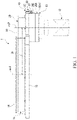
- Fig. 1 is a side view of a rotating jig 1 including a power transmission device 10 according to an embodiment.
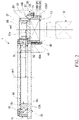
- Fig. 2 is a longitudinal sectional view of the rotating jig 1.
- the rotating jig 1 is used for, for example, welding of instruments.
- the rotating jig 1 includes a ring gear 11 (first gear) serving as a rotation output unit, a motor 12 serving as a drive source, and a speed reducer 13 for decelerating the rotation of the motor 12 and transmitting the decelerated rotation to the ring gear 11.
- An output unit 13a of the speed reducer 13 has a pinion gear 20 mounted thereto.
- the teeth 20a (see Fig. 3 ) of the pinion gear 20 engage with the external teeth 11a (see Fig. 3 ) of the ring gear 11 to transmit the rotation of the pinion gear 20 to the ring gear 11.
- the power transmitting path portion from the speed reducer 13 to the ring gear 11 in the rotating jig 1 constitutes
- An adapter ring 14 is fixed to one end surface of the ring gear 11 in the axial direction.
- the adapter ring 14 has mounted thereto an instrument fixing plate or the like (not shown) that supports an object to be rotated (for example, an object to be welded).
- the ring gear 11 is rotatably supported on a base member 15 via a bearing 16.
- the base member 15 includes a first annular portion 15A having a large diameter and a second annular portion 15B having a small diameter.
- On one axial end surface of the first annular portion 15A there is fixed an inner race 16i of the bearing 16.
- the speed reducer 13 On the second annular portion 15B, the speed reducer 13 is fixed.
- the second annular portion 15B is integrally formed on the outer periphery of the first annular portion 15A.
- Both the first annular portion 15A and the second annular portion 15B have a short-axis cylindrical shape.
- the first annular portion 15A and the second annular portion 15B may be formed of separate parts and fixed to each other by a fixing means such as a bolt.
- the sign ax1 in Figs. 1 and 2 denotes the central axis of the first annular portion 15A.
- the sign ax2 denotes the central axis of the second annular portion 15B.
- the inner race 16i of the bearing 16 and the ring gear 11, which is supported on the outer peripheral side of the inner race 16i via rolling elements 16r (for example, balls), are coaxial with each other and centered at the central axis ax1.
- the ring gear 11 is rotatable around the central axis ax1.
- the first annular portion 15A of the base member 15 is mounted to a support device (not shown) supporting the rotating jig 1.
- the ring gear 11 and the pinion gear 20 are externally covered by a transmission cover 50 formed of a metal plate.
- the transmission cover 50 is fixed to the base member 15.
- Fig. 3 is a partial sectional perspective view of the rotating jig 1 cut at the same portion as in Fig. 2 .
- Fig. 3 does not show the transmission cover 50 externally covering the ring gear 11 and the pinion gear 20.
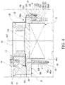
- Fig. 4 is an enlarged sectional view of the part IV of Fig. 2 .
- the speed reducer 13 includes a housing case 25A having a substantially cylindrical shape.
- the housing case 25A houses a reduction mechanism.
- the output unit 13a is provided at one end of the speed reducer 13 in the axial direction.
- the output unit 13a has the pinion gear 20 mounted thereto.
- On the other end of the speed reducer 13 in the axial direction there is mounted a motor 12 serving as a drive source.
- a fixing flange 25Af On the outer periphery of the end portion of the housing case 25A on the motor 12 side, there is integrally formed a fixing flange 25Af having an annular shape and projecting radially outward.
- the fixing flange 25Af has a plurality of shaft holes 42a extending therethrough in the axial direction.
- the shaft holes 42a formed in the fixing flange 25Af are arranged at regular intervals in the circumferential direction.
- Each of the shaft holes 42a is penetrated by a fastening bolt 40 (fastening member) for fixing the speed reducer 13 to the second annular portion 15B of the base member 15.
- An adapter block 25B having a cylindrical shape is fitted on the portion of the housing case 25A of the speed reducer 13 that is adjacent to the output unit 13a side of the fixing flange 25Af.
- the adapter block 25B has substantially the same outer diameter as the fixing flange 25Af of the housing case 25A. In other words, the radial thickness of the adapter block 25B is substantially the same as the radial projection width of the fixing flange 25Af.
- the adapter block 25B has a plurality of shaft holes 42b extending therethrough in the axial direction.
- the shaft holes 42b formed in the adapter block 25B are arranged at regular intervals in the circumferential direction, so as to form one-to-one correspondence to the shaft holes 42a in the fixing flange 25Af.
- Each of the shaft holes 42b is penetrated by the fastening bolt 40 for fixing the speed reducer 13 to the second annular portion 15B of the base member 15.
- the speed reducer 13 is fixed to the second annular portion 15B with a plurality of fastening bolts 40 along with the adapter block 25B fitted on the housing case 25A.
- the second annular portion 15B has screw holes 35 formed therein for threadably receiving the distal end portions of the shafts 40a of the plurality of fastening bolts 40.
- the screw holes 35 formed in the second annular portion 15B are arranged at regular intervals in the circumferential direction.
- the outer diameter of the shaft 40a of each fastening bolt 40 is smaller than the inner diameter of the shaft hole 42a of the housing case 25A (fixing flange 25Af) and the inner diameter of the shaft hole 42b of the adapter block 25B.
- the outer diameter of the shaft 40a of each fastening bolt 40 is set such that a gap d is formed between the shaft 40a and the shaft holes 42a, 42b and the gap d allows radial displacement of the housing case 25A and the adapter block 25B. Accordingly, the radial positions of the housing case 25A and the adapter block 25B can be adjusted when they are temporarily fastened with the fastening bolts 40 to the second annular portion 15B (not fastened completely).
- the displacement of the housing case 25A and the adapter block 25B for the position adjustment is restricted by a position adjusting unit 30 (described later) to the direction of the line connecting between the central axis ax2 of the pinion gear 20 and the central axis ax1 of the ring gear 11 (hereinafter referred to as "the gear-to-gear direction Di").
- a washer 45 having an annular shape is placed on the end surface of the fixing flange 25Af (the end surface opposite to the adapter block 25B).
- the washer 45 has a plurality of insertion holes 45a formed therein through which the shafts 40a of the fastening bolts 40 are inserted.
- the heads of the fastening bolts 40 contact with the peripheries of the insertion holes 45a.
- the inner diameter of the insertion holes 45a is smaller than the inner diameters of the shaft holes 42a, 42b of the housing case 25A and the adapter block 25B.
- the housing case 25A and the adapter block 25B constitute a support block 25 that rotatably supports the pinion gear 20 (second gear).
- a retaining block 32 shaped like a rectangular plate. A part of the retaining block 32 projects from the second annular portion 15B on the other end side in the axial direction of the second annular portion 15B.
- the retaining block 32 is fixed to a planed portion of the outer peripheral surface of the second annular portion 15B by bolt fastening, for example.
- the portion of the retaining block 32 projecting from the second annular portion 15B (hereinafter referred to as “the projecting portion”) has a surface facing outward in the radial direction of the second annular portion 15B, and this surface is cut out into a stepped shape. This portion cut out is hereinafter referred to as “the cut-out portion 32b.”
- the projecting portion (the portion facing the cut-out portion 32b) has an insertion hole 32a formed therein through which a screw shaft 31a of an adjustment screw 31 is inserted.
- the insertion hole 32a extends along the gear-to-gear direction Di.
- the screw shaft 31a of the adjustment screw 31 is rotatably supported on the retaining block 32 at one end side in the axial direction of the screw shaft 31a. Accordingly, the screw shaft 31a of the adjustment screw 31 rotatably supported in the insertion hole 32a extends along the gear-to-gear direction Di.
- a displacement restraining block 33 On the outer side surface of the retaining block 32 (the surface opposite to the side contacting with the outer peripheral surface of the second annular portion 15B), there is mounted a displacement restraining block 33 shaped like a rectangular plate smaller than the retaining block 32.
- the displacement restraining block 33 is fixed to the outer side surface of the retaining block 32 by bolt fastening, for example.
- the displacement restraining block 33 extends to the position facing the cut-out portion 32b of the retaining block 32 and faces the outer side surface of the projecting portion of the retaining block 32 across the cut-out portion 32b.
- the head 31b of the adjustment screw 31 retained in the insertion hole 32a.
- the head 31b contacts with the retaining block 32 and the displacement restraining block 33. In this way, the adjustment screw 31 is restrained from being displaced in the axial direction thereof.
- a tool insertion hole 33a that is coaxial with the insertion hole 32a.
- a tool such as a hexagon wrench can be inserted through the tool insertion hole 33a.
- a tool such as a hexagon wrench is inserted into the tool insertion hole 33a, and the distal end portion of the tool is fitted into the hexagonal hole in the head 31b of the adjustment screw 31. The tool is then rotated to rotate the adjustment screw 31.
- a screw hole 25Ba At the position in the outer peripheral wall of the adapter block 25B facing the insertion hole 32a of the retaining block 32, there is formed a screw hole 25Ba.
- the screw hole 25Ba extends along the gear-to-gear direction Di.
- the adjustment screw 31 is screwed into the adapter block 25B at the other axial end side of the screw shaft 31a.
- the portion of the screw shaft 31a on the head 31b side is retained by the retaining block 32, and the portion of the screw shaft 31a on the distal end side is supported by the adapter block 25B.
- the adapter block 25B which is temporarily fastened with the fastening bolts 40 to the second annular portion 15B along with the housing case 25A (speed reducer 13), advances or retracts along the gear-to-gear direction Di in accordance with the direction and the amount of rotation of the adjustment screw 31.
- the pinion gear 20 moves closer to the ring gear 11 in accordance with the amount of rotation, resulting in a larger engagement depth between these gears.
- the pinion gear 20 moves away from the ring gear 11 in accordance with the amount of rotation, resulting in a smaller engagement depth between these gears.
- the screw mechanism including the adjustment screw 31, the retaining block 32, the displacement restraining block 33, and the screw hole 25Ba of the adapter block 25B constitutes a position adjusting unit 30 for adjusting the relative positions of the support block 25 and the base member 15 along the gear-to-gear direction Di.
- the power transmission device 10 used in the rotating jig 1 of the embodiment is configured such that the engagement depth between the pinion gear 20 and the ring gear 11 can be adjusted after shipping in the following matter.
- the plurality of fastening bolts 40 are loosened with a tool, resulting in the temporarily fastened state of the support block 25 (the housing case 25A and the adapter block 25B).
- the support block 25 can be displaced along the gear-to-gear direction Di.
- the engagement between the pinion gear 20 and the ring gear 11 is adjusted to the optimal state.
- the plurality of fastening bolts 40 are then fastened with the tool, so as to secure the support block 25 (the housing case 25A and the adapter block 25B) to the second annular portion 15B of the base member 15.
- the power transmission device 10 of the embodiment includes: the position adjusting unit 30 for adjusting the relative positions of the support block 25 supporting the pinion gear 20 and the base member 15 supporting the ring gear 11; and a fixing unit (the fastening bolts 40, the shaft holes 42a, 42b, and the screw holes 35) for fixing the relative positions of the support block 25 and the base member 15. Therefore, the position adjusting unit 30 can adjust the relative positions of the support block 25 and the base member 15 such that the pinion gear 20 and the ring gear 11 engage with each other in the optimal manner. In this state, the fixing unit can fix the relative positions of the support block 25 and the base member 15. Accordingly, the power transmission device 10 of the embodiment makes it possible to readily adjust the engagement between the pinion gear 20 and the ring gear 11 in the optimal manner when necessary.
- the position adjusting unit 30 for adjusting the position of the support block 25 relative to the base member 15 includes the adjustment screw 31 (screw shaft 31a) extending along the gear-to-gear direction Di.
- the adjustment screw 31 is positioned such that one axial end side of the screw shaft 31a is rotatably retained on a member on the base member 15 side and the other axial end side of the screw shaft 31a is screwed into the support block 25 (adapter block 25B).
- the member on the base member 15 side refers to the base member 15 itself or a member fixed to the base member 15. Therefore, fine adjustment is readily accomplished in the engagement between the pinion gear 20 and the ring gear 11 by rotation of the adjustment screw 31.
- the adjustment screw 31 is directly screwed into the support block 25 (adapter block 25B) at the other axial end side thereof. Accordingly, a simple structure including a small number of parts accomplishes the position adjustment for increasing the engagement depth between the gears and the position adjustment for reducing the engagement depth between the gears.
- one axial end side of the adjustment screw 31 of the position adjusting unit 30 is rotatably retained on a member on the base member 15 side, and the other axial end side of the adjustment screw 31 is screwed into the support block 25.
- This configuration is not limitative. It is also possible that one axial end side of the adjustment screw 31 is rotatably supported on the support block 25 and the other axial end side of the adjustment screw 31 is screwed into a member on the base member 15 side.
- the head 31b of the adjustment screw 31 being rotated is not displaced along with the speed reducer 13 along the gear-to-gear direction Di. Accordingly, the adjusting work is facilitated.
- the adjustment screw 31 (screw shaft 31a) of the position adjusting unit 30 extends along the gear-to-gear direction Di. Therefore, in actual operation of the power transmission device 10 (rotating jig 1), the adjustment screw 31 can also receive a large engagement reaction force possibly acting from the ring gear 11 side onto the pinion gear 20 side (speed reducer 13 side). Therefore, it is possible to effectively prevent fine displacement of the pinion gear 20 due to input of a large impact load (engagement reaction force), occurrence of operation noises, breakage of engaging parts, and occurrence of wear.
- the distal end portion of the adjustment screw 31 (screw shaft 31a) is screwed into the adapter block 25B fitted on the outer peripheral surface of the housing case 25A of the speed reducer 13. Therefore, there is no need of forming a screw hole for receiving the distal end portion of the adjustment screw 31 in the housing case 25A of the speed reducer 13. This facilitates the processing work of the housing case 25A and increases the strength of the housing case 25A.
- this configuration can be readily applied to a speed reducer 13 having a different outer diameter if the adapter block 25B is replaced with another having a different inner diameter.
- This configuration is also applicable to a speed reducer 13 different in specifications other than outer diameter such as shaft length if the adapter block 25B is replaced with another. It is also possible that the adapter block 25B is omitted and the distal end portion of the adjustment screw 31 is directly screwed into the peripheral wall of the housing case 25A.
- the fixing unit that fixes the support block 25 to the base member 15 includes: the fastening bolts 40 for fixing the support block 25 to the base member 15; and the shaft holes 42a, 42b provided in the support block 25 so as to be parallel with the axial direction of the pinion gear 20.
- the fastening bolts 40 can be fastened in the direction parallel with the axial direction of the pinion gear 20 (an intersection direction intersecting with the direction in which the engagement depth varies).
- the shaft holes 42a, 42b have such an inner diameter (size) as to allow displacement of the support block 25 in the radial direction. Therefore, when the fastening bolts 40 are loosened, the position of the support block 25 can be adjusted in the radial direction.
- the fastening bolts 40 are slightly loosened, not removed completely.
- the support block 25 is temporarily retained to the base member 15 by the heads of the fastening bolts 40, and in this state, the position of the support block 25 can be readily adjusted.
- the fixing unit that fixes the support block 25 to the base member 15 is not limited to the above configuration, but may be configured in other ways as long as it can fix the support block 25 to the base member 15.
- the shaft holes 42a, 42b with a perfectly circular shape have an inner diameter sufficiently larger than the outer diameter of the shafts 40a of the fastening bolts 40, such that the gap d is maintained between the fastening bolts 40 and the shaft holes 42a, 42b to allow displacement of the support block 25 in the radial direction.
- the shaft holes 42a, 42b through which the fastening bolts 40 are inserted do not have a perfectly circular shape but have such an elongated shape as to maintain a gap allowing the displacement in the gear-to-gear direction Di.
- the shaft holes 42a, 42b formed in the support block 25 have a perfectly circular shape with an inner diameter sufficiently larger than the outer diameter of the shafts 40a of the fastening bolts 40. Accordingly, the processing work of the shaft holes 42a, 42b in the support block 25 is facilitated. Further, when the speed reducers 13 having the same specifications are used in the power transmission device 10 including the position adjusting unit 30 (engagement adjusting device) and a power transmission device not including the position adjusting unit 30, the power transmission device 10 including the position adjusting unit 30 should use the fastening bolts 40 with a smaller shaft diameter than the fastening bolts 40 used for fixing of the power transmission device not including the position adjusting unit 30. Therefore, with this configuration, the speed reducers having the same specifications can be used in the power transmission device 10 including the position adjusting unit 30 and the power transmission device not including the position adjusting unit.
- the main component of the position adjusting unit 30 is the adjustment screw 31 that is rotatably retained to the member on the base member 15 side and having the distal end portion thereof fastened into the support block 25 side.
- the position adjusting unit 30 is not limited to this configuration.
- the position adjusting unit 30 may be constituted by: an adjustment screw that can be operated to push the outer peripheral surface of the support block 25 toward one side in the gear-to-gear direction Di; and a spring member such as a disc spring disposed at the opposed position on the outer periphery of the support block 25 and imparting an elastic reaction force toward the other side in the gear-to-gear direction Di.
- the adjustment screw may be replaced with another operation mechanism such as a lever mechanism.
- the present invention is not limited to the above-described embodiments and can be modified in a variety of designs without deviating from the spirit of the present invention.
- the first gear is formed of the pinion gear 20
- the second gear is formed of the ring gear 11.
- the first gear and the second gear may have any shape and size as along as these gears engage with each other.
- the second gear (pinion gear 20) is rotatably coupled to the speed reducer 13.
- the second gear is not necessarily coupled to the speed reducer 13.
- the second gear may be directly coupled to a power source such as the motor 12 without the speed reducer 13 interposed therebetween.
- application of the power transmission device 10 is not limited to the rotating jig 1.
- the power transmission device 10 can be applied to moving parts of other various apparatuses such as turning parts of a robot arm.
Landscapes
- Engineering & Computer Science (AREA)
- General Engineering & Computer Science (AREA)
- Mechanical Engineering (AREA)
- Robotics (AREA)
- General Details Of Gearings (AREA)
- Gear Transmission (AREA)
- Gears, Cams (AREA)
Abstract
Description
- The present disclosure relates to a power transmission device for transmitting rotational power to an object of operation, and also relates to an engagement adjusting device for a gear mechanism.
- In many mechanical devices such as turntables and industrial robots, the power of a drive source is transmitted to an object of operation via a power transmission device including a gear mechanism (see, for example, Patent Literature 1).
- In mechanical devices required to have a high operation accuracy, engagement accuracy is important for the gear mechanism used in the power transmission device. Therefore, in the manufacturing process of the power transmission device used in such mechanical devices, gears in the gear mechanism are assembled to a gear support with a high accuracy using positioning pins or the like.
- Patent Literature 1:
Japanese Patent Application Publication No. 2019-158143 - In the power transmission device, the engagement between gears may vary due to the service environment after shipping and wear of parts resulting from long-time service.
- In the manufacturing process of conventional power transmission devices, gears are assembled to a gear support with a high accuracy. However, no measures are taken against the variation of the engagement between the gears after shipping. Therefore, if the engagement between gears has varied largely after shipping, it is necessary to disassemble the power transmission device for replacement of parts or reassembling.
- The present invention provides a power transmission device and an engagement adjusting device for a gear mechanism, capable of readily adjusting the engagement between gears to an optimal state as necessary.
- (1) A power transmission device according to one aspect of the present invention comprises: a first gear; a base member rotatably supporting the first gear; a second gear engaging with the first gear so as to be able to transmit power; a support block rotatably supporting the second gear; a position adjusting unit for adjusting relative positions of the support block and the base member in a direction in which an engagement depth between the second gear and the first gear varies; and a fixing unit for fixing the relative positions of the support block and the base member.
- (2) In the power transmission device of (1), it is also possible that the position adjusting unit is constituted by a screw mechanism including an adjustment screw having a screw shaft extending in the direction in which the engagement depth between the second gear and the first gear varies. It is also possible that the screw mechanism is rotatably retained on one of the support block and the base member at one end side in the axial direction of the screw shaft, and the screw mechanism is screwed into the other of the support block and the base member at the other end side in the axial direction.
- (3) In the power transmission device of (2), it is also possible that the support block includes: a housing case of a speed reducer, the speed reducer being configured to transmit decelerated power to the second gear; and an adapter block fitted on an outer peripheral surface of the housing case. In the screw mechanism, it is also possible that the screw mechanism is rotatably retained on the base member at the one end side, and the screw mechanism is screwed into the adapter block at the other end side.
- (4) In the power transmission device of any one of (1) to (3), it is also possible that the fixing unit includes: a fastening member configured to be fastened in an intersection direction intersecting with the direction in which the engagement depth between the second gear and the first gear varies, the fastening member being configured to fix the support block to the base member; and a shaft hole provided in the support block along the intersection direction and penetrated by a shaft of the fastening member. It is also possible that the shaft hole has such an inner shape or a size as to allow displacement of the support block in the direction in which the engagement depth between the second gear and the first gear varies.
- (5) In the power transmission device of (4), it is also possible that the shaft of the fastening member has such an outer diameter as to form a gap between the shaft and the shaft hole, and the gap is formed to allow the displacement.
- (6) An engagement adjusting device for a gear mechanism according to one aspect of the present invention comprises: a base member rotatably supporting a first gear; a support block rotatably supporting a second gear, the second gear engaging with the first gear so as to be able to transmit power; a position adjusting unit for adjusting relative positions of the support block and the base member in a direction in which an engagement depth between the second gear and the first gear varies; and a fixing unit for fixing the relative positions of the support block and the base member.
- Each of the power transmission device and the engagement adjusting device for a gear mechanism described above includes: the position adjusting unit for adjusting the relative positions of the support block supporting the second gear and the base member supporting the first gear; and the fixing unit for fixing the relative positions of the support block and the base member. Therefore, the position adjusting unit can adjust the relative positions of the support block and the base member such that the gears engage with each other in the optimal manner, and in this state, the fixing unit can fix the relative positions of the support block and the base member. Accordingly, with the above configuration, it is possible to readily adjust the engagement between the second gear and the first gear in the optimal manner when necessary.
-
-
Fig. 1 is a side view of a rotating jig including a power transmission device according to an embodiment. -
Fig. 2 is a longitudinal sectional view of the rotating jig according to the embodiment. -
Fig. 3 is a partial sectional perspective view of the rotating jig according to the embodiment. -
Fig. 4 is an enlarged sectional view of the part IV ofFig. 2 . - The embodiments of the present invention will be hereinafter described with reference to the drawings.
-
Fig. 1 is a side view of a rotating jig 1 including apower transmission device 10 according to an embodiment.Fig. 2 is a longitudinal sectional view of the rotating jig 1. The rotating jig 1 is used for, for example, welding of instruments. The rotating jig 1 includes a ring gear 11 (first gear) serving as a rotation output unit, amotor 12 serving as a drive source, and aspeed reducer 13 for decelerating the rotation of themotor 12 and transmitting the decelerated rotation to thering gear 11. Anoutput unit 13a of thespeed reducer 13 has apinion gear 20 mounted thereto. Theteeth 20a (seeFig. 3 ) of thepinion gear 20 engage with theexternal teeth 11a (seeFig. 3 ) of thering gear 11 to transmit the rotation of thepinion gear 20 to thering gear 11. In the embodiment, the power transmitting path portion from the speed reducer 13 to thering gear 11 in the rotating jig 1 constitutes thepower transmission device 10. - An
adapter ring 14 is fixed to one end surface of thering gear 11 in the axial direction. Theadapter ring 14 has mounted thereto an instrument fixing plate or the like (not shown) that supports an object to be rotated (for example, an object to be welded). - The
ring gear 11 is rotatably supported on abase member 15 via abearing 16. Thebase member 15 includes a firstannular portion 15A having a large diameter and a secondannular portion 15B having a small diameter. On one axial end surface of the firstannular portion 15A, there is fixed aninner race 16i of thebearing 16. On the secondannular portion 15B, thespeed reducer 13 is fixed. In the embodiment, the secondannular portion 15B is integrally formed on the outer periphery of the firstannular portion 15A. Both the firstannular portion 15A and the secondannular portion 15B have a short-axis cylindrical shape. The firstannular portion 15A and the secondannular portion 15B may be formed of separate parts and fixed to each other by a fixing means such as a bolt. - The sign ax1 in
Figs. 1 and2 denotes the central axis of the firstannular portion 15A. The sign ax2 denotes the central axis of the secondannular portion 15B. Theinner race 16i of thebearing 16 and thering gear 11, which is supported on the outer peripheral side of theinner race 16i viarolling elements 16r (for example, balls), are coaxial with each other and centered at the central axis ax1. Thering gear 11 is rotatable around the central axis ax1. The firstannular portion 15A of thebase member 15 is mounted to a support device (not shown) supporting the rotating jig 1. Thering gear 11 and thepinion gear 20 are externally covered by atransmission cover 50 formed of a metal plate. Thetransmission cover 50 is fixed to thebase member 15. -
Fig. 3 is a partial sectional perspective view of the rotating jig 1 cut at the same portion as inFig. 2 .Fig. 3 does not show thetransmission cover 50 externally covering thering gear 11 and thepinion gear 20.Fig. 4 is an enlarged sectional view of the part IV ofFig. 2 . Thespeed reducer 13 includes a housing case 25A having a substantially cylindrical shape. The housing case 25A houses a reduction mechanism. Theoutput unit 13a is provided at one end of the speed reducer 13 in the axial direction. Theoutput unit 13a has thepinion gear 20 mounted thereto. On the other end of the speed reducer 13 in the axial direction, there is mounted amotor 12 serving as a drive source. On the outer periphery of the end portion of the housing case 25A on themotor 12 side, there is integrally formed a fixing flange 25Af having an annular shape and projecting radially outward. The fixing flange 25Af has a plurality ofshaft holes 42a extending therethrough in the axial direction. The shaft holes 42a formed in the fixing flange 25Af are arranged at regular intervals in the circumferential direction. Each of theshaft holes 42a is penetrated by a fastening bolt 40 (fastening member) for fixing thespeed reducer 13 to the secondannular portion 15B of thebase member 15. - An
adapter block 25B having a cylindrical shape is fitted on the portion of the housing case 25A of thespeed reducer 13 that is adjacent to theoutput unit 13a side of the fixing flange 25Af. Theadapter block 25B has substantially the same outer diameter as the fixing flange 25Af of the housing case 25A. In other words, the radial thickness of theadapter block 25B is substantially the same as the radial projection width of the fixing flange 25Af. Theadapter block 25B has a plurality ofshaft holes 42b extending therethrough in the axial direction. The shaft holes 42b formed in theadapter block 25B are arranged at regular intervals in the circumferential direction, so as to form one-to-one correspondence to theshaft holes 42a in the fixing flange 25Af. Each of theshaft holes 42b is penetrated by thefastening bolt 40 for fixing thespeed reducer 13 to the secondannular portion 15B of thebase member 15. - The
speed reducer 13 is fixed to the secondannular portion 15B with a plurality offastening bolts 40 along with theadapter block 25B fitted on the housing case 25A. The secondannular portion 15B has screw holes 35 formed therein for threadably receiving the distal end portions of theshafts 40a of the plurality offastening bolts 40. The screw holes 35 formed in the secondannular portion 15B are arranged at regular intervals in the circumferential direction. - The outer diameter of the
shaft 40a of eachfastening bolt 40 is smaller than the inner diameter of theshaft hole 42a of the housing case 25A (fixing flange 25Af) and the inner diameter of theshaft hole 42b of theadapter block 25B. Specifically, the outer diameter of theshaft 40a of eachfastening bolt 40 is set such that a gap d is formed between theshaft 40a and theshaft holes adapter block 25B. Accordingly, the radial positions of the housing case 25A and theadapter block 25B can be adjusted when they are temporarily fastened with thefastening bolts 40 to the secondannular portion 15B (not fastened completely). Actually, the displacement of the housing case 25A and theadapter block 25B for the position adjustment is restricted by a position adjusting unit 30 (described later) to the direction of the line connecting between the central axis ax2 of thepinion gear 20 and the central axis ax1 of the ring gear 11 (hereinafter referred to as "the gear-to-gear direction Di"). - In fixing the housing case 25A and the
adapter block 25B to the secondannular portion 15B with thefastening bolts 40, awasher 45 having an annular shape is placed on the end surface of the fixing flange 25Af (the end surface opposite to theadapter block 25B). Thewasher 45 has a plurality ofinsertion holes 45a formed therein through which theshafts 40a of thefastening bolts 40 are inserted. The heads of thefastening bolts 40 contact with the peripheries of theinsertion holes 45a. The inner diameter of theinsertion holes 45a is smaller than the inner diameters of theshaft holes adapter block 25B. Therefore, even when thefastening bolts 40 are to the standard with a smaller diameter than theshaft holes adapter block 25B, the fastening load acting on the heads of thefastening bolts 40 can be securely received by thewasher 45 and transmitted to the housing case 25A and theadapter block 25B. In the embodiment, the housing case 25A and theadapter block 25B constitute asupport block 25 that rotatably supports the pinion gear 20 (second gear). - On the outer peripheral surface of the second
annular portion 15B of thebase member 15, there is mounted a retainingblock 32 shaped like a rectangular plate. A part of the retainingblock 32 projects from the secondannular portion 15B on the other end side in the axial direction of the secondannular portion 15B. The retainingblock 32 is fixed to a planed portion of the outer peripheral surface of the secondannular portion 15B by bolt fastening, for example. - The portion of the retaining
block 32 projecting from the secondannular portion 15B (hereinafter referred to as "the projecting portion") has a surface facing outward in the radial direction of the secondannular portion 15B, and this surface is cut out into a stepped shape. This portion cut out is hereinafter referred to as "the cut-outportion 32b." The projecting portion (the portion facing the cut-outportion 32b) has aninsertion hole 32a formed therein through which ascrew shaft 31a of anadjustment screw 31 is inserted. - The
insertion hole 32a extends along the gear-to-gear direction Di. In theinsertion hole 32a, thescrew shaft 31a of theadjustment screw 31 is rotatably supported on the retainingblock 32 at one end side in the axial direction of thescrew shaft 31a. Accordingly, thescrew shaft 31a of theadjustment screw 31 rotatably supported in theinsertion hole 32a extends along the gear-to-gear direction Di. - On the outer side surface of the retaining block 32 (the surface opposite to the side contacting with the outer peripheral surface of the second
annular portion 15B), there is mounted adisplacement restraining block 33 shaped like a rectangular plate smaller than the retainingblock 32. Thedisplacement restraining block 33 is fixed to the outer side surface of the retainingblock 32 by bolt fastening, for example. - The
displacement restraining block 33 extends to the position facing the cut-outportion 32b of the retainingblock 32 and faces the outer side surface of the projecting portion of the retainingblock 32 across the cut-outportion 32b. In the gap formed by the cut-outportion 32b between the retainingblock 32 and thedisplacement restraining block 33, there is located the head 31b of theadjustment screw 31 retained in theinsertion hole 32a. In the gap formed by the cut-outportion 32b, thehead 31b contacts with the retainingblock 32 and thedisplacement restraining block 33. In this way, theadjustment screw 31 is restrained from being displaced in the axial direction thereof. - At the position in the
displacement restraining block 33 facing theinsertion hole 32a of the retainingblock 32, there is formed atool insertion hole 33a that is coaxial with theinsertion hole 32a. A tool such as a hexagon wrench can be inserted through thetool insertion hole 33a. To rotate theadjustment screw 31, a tool such as a hexagon wrench is inserted into thetool insertion hole 33a, and the distal end portion of the tool is fitted into the hexagonal hole in thehead 31b of theadjustment screw 31. The tool is then rotated to rotate theadjustment screw 31. - At the position in the outer peripheral wall of the
adapter block 25B facing theinsertion hole 32a of the retainingblock 32, there is formed a screw hole 25Ba. The screw hole 25Ba extends along the gear-to-gear direction Di. Theadjustment screw 31 is screwed into theadapter block 25B at the other axial end side of thescrew shaft 31a. Thus, the portion of thescrew shaft 31a on thehead 31b side is retained by the retainingblock 32, and the portion of thescrew shaft 31a on the distal end side is supported by theadapter block 25B. When theadjustment screw 31 is rotated, theadapter block 25B, which is temporarily fastened with thefastening bolts 40 to the secondannular portion 15B along with the housing case 25A (speed reducer 13), advances or retracts along the gear-to-gear direction Di in accordance with the direction and the amount of rotation of theadjustment screw 31. - Specifically, when the
adjustment screw 31 is rotated in one direction, thepinion gear 20 moves closer to thering gear 11 in accordance with the amount of rotation, resulting in a larger engagement depth between these gears. When theadjustment screw 31 is rotated in the other direction, thepinion gear 20 moves away from thering gear 11 in accordance with the amount of rotation, resulting in a smaller engagement depth between these gears. - In the embodiment, the screw mechanism including the
adjustment screw 31, the retainingblock 32, thedisplacement restraining block 33, and the screw hole 25Ba of theadapter block 25B constitutes aposition adjusting unit 30 for adjusting the relative positions of thesupport block 25 and thebase member 15 along the gear-to-gear direction Di. - The
power transmission device 10 used in the rotating jig 1 of the embodiment is configured such that the engagement depth between thepinion gear 20 and thering gear 11 can be adjusted after shipping in the following matter. - First, the plurality of
fastening bolts 40 are loosened with a tool, resulting in the temporarily fastened state of the support block 25 (the housing case 25A and theadapter block 25B). In this state, thesupport block 25 can be displaced along the gear-to-gear direction Di. - Next, in this state, a tool is inserted into the
tool insertion hole 33a of thedisplacement restraining block 33. The too is then used to rotate theadjustment screw 31 of theposition adjusting unit 30. Thus, thespeed reducer 13 is displaced along the gear-to-gear direction Di such that thepinion gear 20 and thering gear 11 engage with each other in the optimal manner. - In this way, the engagement between the
pinion gear 20 and thering gear 11 is adjusted to the optimal state. The plurality offastening bolts 40 are then fastened with the tool, so as to secure the support block 25 (the housing case 25A and theadapter block 25B) to the secondannular portion 15B of thebase member 15. - The
power transmission device 10 of the embodiment includes: theposition adjusting unit 30 for adjusting the relative positions of thesupport block 25 supporting thepinion gear 20 and thebase member 15 supporting thering gear 11; and a fixing unit (thefastening bolts 40, theshaft holes support block 25 and thebase member 15. Therefore, theposition adjusting unit 30 can adjust the relative positions of thesupport block 25 and thebase member 15 such that thepinion gear 20 and thering gear 11 engage with each other in the optimal manner. In this state, the fixing unit can fix the relative positions of thesupport block 25 and thebase member 15. Accordingly, thepower transmission device 10 of the embodiment makes it possible to readily adjust the engagement between thepinion gear 20 and thering gear 11 in the optimal manner when necessary. - Further, in the
power transmission device 10 of the embodiment, theposition adjusting unit 30 for adjusting the position of thesupport block 25 relative to thebase member 15 includes the adjustment screw 31 (screwshaft 31a) extending along the gear-to-gear direction Di. Theadjustment screw 31 is positioned such that one axial end side of thescrew shaft 31a is rotatably retained on a member on thebase member 15 side and the other axial end side of thescrew shaft 31a is screwed into the support block 25 (adapter block 25B). Note that the member on thebase member 15 side refers to thebase member 15 itself or a member fixed to thebase member 15. Therefore, fine adjustment is readily accomplished in the engagement between thepinion gear 20 and thering gear 11 by rotation of theadjustment screw 31. In particular, in this configuration, theadjustment screw 31 is directly screwed into the support block 25 (adapter block 25B) at the other axial end side thereof. Accordingly, a simple structure including a small number of parts accomplishes the position adjustment for increasing the engagement depth between the gears and the position adjustment for reducing the engagement depth between the gears. - In the embodiment, one axial end side of the
adjustment screw 31 of theposition adjusting unit 30 is rotatably retained on a member on thebase member 15 side, and the other axial end side of theadjustment screw 31 is screwed into thesupport block 25. This configuration is not limitative. It is also possible that one axial end side of theadjustment screw 31 is rotatably supported on thesupport block 25 and the other axial end side of theadjustment screw 31 is screwed into a member on thebase member 15 side. However, in the case where one axial end side of theadjustment screw 31 is rotatably retained on a member on thebase member 15 side, as in the embodiment, thehead 31b of theadjustment screw 31 being rotated is not displaced along with thespeed reducer 13 along the gear-to-gear direction Di. Accordingly, the adjusting work is facilitated. - Further, in the
power transmission device 10 of the embodiment, the adjustment screw 31 (screwshaft 31a) of theposition adjusting unit 30 extends along the gear-to-gear direction Di. Therefore, in actual operation of the power transmission device 10 (rotating jig 1), theadjustment screw 31 can also receive a large engagement reaction force possibly acting from thering gear 11 side onto thepinion gear 20 side (speed reducer 13 side). Therefore, it is possible to effectively prevent fine displacement of thepinion gear 20 due to input of a large impact load (engagement reaction force), occurrence of operation noises, breakage of engaging parts, and occurrence of wear. - Further, in the
power transmission device 10 of the embodiment, the distal end portion of the adjustment screw 31 (screwshaft 31a) is screwed into theadapter block 25B fitted on the outer peripheral surface of the housing case 25A of thespeed reducer 13. Therefore, there is no need of forming a screw hole for receiving the distal end portion of theadjustment screw 31 in the housing case 25A of thespeed reducer 13. This facilitates the processing work of the housing case 25A and increases the strength of the housing case 25A. - Further, this configuration can be readily applied to a
speed reducer 13 having a different outer diameter if theadapter block 25B is replaced with another having a different inner diameter. This configuration is also applicable to aspeed reducer 13 different in specifications other than outer diameter such as shaft length if theadapter block 25B is replaced with another. It is also possible that theadapter block 25B is omitted and the distal end portion of theadjustment screw 31 is directly screwed into the peripheral wall of the housing case 25A. - Further, in the
power transmission device 10 of the embodiment, the fixing unit that fixes thesupport block 25 to thebase member 15 includes: thefastening bolts 40 for fixing thesupport block 25 to thebase member 15; and theshaft holes support block 25 so as to be parallel with the axial direction of thepinion gear 20. Thefastening bolts 40 can be fastened in the direction parallel with the axial direction of the pinion gear 20 (an intersection direction intersecting with the direction in which the engagement depth varies). The shaft holes 42a, 42b have such an inner diameter (size) as to allow displacement of thesupport block 25 in the radial direction. Therefore, when thefastening bolts 40 are loosened, the position of thesupport block 25 can be adjusted in the radial direction. - In particular, to adjust the position of the
support block 25 in the radial direction, thefastening bolts 40 are slightly loosened, not removed completely. Thus, thesupport block 25 is temporarily retained to thebase member 15 by the heads of thefastening bolts 40, and in this state, the position of thesupport block 25 can be readily adjusted. However, the fixing unit that fixes thesupport block 25 to thebase member 15 is not limited to the above configuration, but may be configured in other ways as long as it can fix thesupport block 25 to thebase member 15. - In the embodiment, the
shaft holes shafts 40a of thefastening bolts 40, such that the gap d is maintained between thefastening bolts 40 and theshaft holes support block 25 in the radial direction. However, it is also possible that theshaft holes fastening bolts 40 are inserted do not have a perfectly circular shape but have such an elongated shape as to maintain a gap allowing the displacement in the gear-to-gear direction Di. - In the
power transmission device 10 of the embodiment, theshaft holes support block 25 have a perfectly circular shape with an inner diameter sufficiently larger than the outer diameter of theshafts 40a of thefastening bolts 40. Accordingly, the processing work of theshaft holes support block 25 is facilitated. Further, when thespeed reducers 13 having the same specifications are used in thepower transmission device 10 including the position adjusting unit 30 (engagement adjusting device) and a power transmission device not including theposition adjusting unit 30, thepower transmission device 10 including theposition adjusting unit 30 should use thefastening bolts 40 with a smaller shaft diameter than thefastening bolts 40 used for fixing of the power transmission device not including theposition adjusting unit 30. Therefore, with this configuration, the speed reducers having the same specifications can be used in thepower transmission device 10 including theposition adjusting unit 30 and the power transmission device not including the position adjusting unit. - In the above embodiment, the main component of the
position adjusting unit 30 is theadjustment screw 31 that is rotatably retained to the member on thebase member 15 side and having the distal end portion thereof fastened into thesupport block 25 side. However, theposition adjusting unit 30 is not limited to this configuration. For example, theposition adjusting unit 30 may be constituted by: an adjustment screw that can be operated to push the outer peripheral surface of thesupport block 25 toward one side in the gear-to-gear direction Di; and a spring member such as a disc spring disposed at the opposed position on the outer periphery of thesupport block 25 and imparting an elastic reaction force toward the other side in the gear-to-gear direction Di. In this case, the adjustment screw may be replaced with another operation mechanism such as a lever mechanism. - The present invention is not limited to the above-described embodiments and can be modified in a variety of designs without deviating from the spirit of the present invention. For example, in the above embodiment, the first gear is formed of the
pinion gear 20, and the second gear is formed of thering gear 11. However, the first gear and the second gear may have any shape and size as along as these gears engage with each other. - Further, in the above embodiment, the second gear (pinion gear 20) is rotatably coupled to the
speed reducer 13. However, the second gear is not necessarily coupled to thespeed reducer 13. For example, the second gear may be directly coupled to a power source such as themotor 12 without thespeed reducer 13 interposed therebetween. - Further, application of the
power transmission device 10 is not limited to the rotating jig 1. Thepower transmission device 10 can be applied to moving parts of other various apparatuses such as turning parts of a robot arm. -
- 10
- power transmission device
- 11
- ring gear (first gear)
- 13
- speed reducer
- 15
- base member
- 20
- pinion gear (second gear)
- 25
- support block
- 25A
- housing case
- 25B
- adapter block
- 30
- position adjusting unit
- 31a
- screw shaft
- 35
- screw hole (fixing unit)
- 40
- fastening bolt (fastening member, fixing unit)
- 40a
- shaft
- 42a,42b
- shaft hole (fixing unit)
Claims (6)
- A power transmission device (10) comprising:a first gear (11);a base member (15) rotatably supporting the first gear (11);a second gear (20) engaging with the first gear (11) so as to be able to transmit power;a support block (25) rotatably supporting the second gear (20);a position adjusting unit (30) for adjusting relative positions of the support block (25) and the base member (15) in a direction in which an engagement depth between the second gear (20) and the first gear (11) varies; anda fixing unit for fixing the relative positions of the support block (25) and the base member (15).
- The power transmission device (10) of claim 1,wherein the position adjusting unit (30) is constituted by a screw mechanism including an adjustment screw having a screw shaft (31a) extending in the direction in which the engagement depth between the second gear (20) and the first gear (11) varies, andwherein the screw mechanism is rotatably retained on one of the support block (25) and the base member (15) at one end side in the axial direction of the screw shaft (31a), and the screw mechanism is screwed into the other of the support block (25) and the base member (15) at the other end side in the axial direction.
- The power transmission device (10) of claim 2,wherein the support block (25) includes:a housing case (25A) of a speed reducer (13), the speed reducer (13) being configured to transmit decelerated power to the second gear (20); andan adapter block (25B) fitted on an outer peripheral surface of the housing case (25A),wherein the screw mechanism is rotatably retained on the base member (15) at the one end side, and the screw mechanism is screwed into the adapter block (25B) at the other end side.
- The power transmission device (10) of any one of claims 1 to 3,
wherein the fixing unit includes:a fastening member (40) configured to be fastened in an intersection direction intersecting with the direction in which the engagement depth between the second gear (20) and the first gear (10) varies, the fastening member (40) being configured to fix the support block (25) to the base member (15); anda shaft hole (42a, 42b) provided in the support block (25) along the intersection direction and penetrated by a shaft (40a) of the fastening member (40), andwherein the shaft hole (42a, 42b) has such an inner shape or a size as to allow displacement of the support block (25) in the direction in which the engagement depth between the second gear (20) and the first gear (11) varies. - The power transmission device (10) of claim 4, wherein the shaft (40a) of the fastening member (40) has such an outer diameter as to form a gap (d) between the shaft (40a) and the shaft hole (42a, 42b), and the gap (d) is formed to allow the displacement.
- An engagement adjusting device for a gear mechanism, comprising:a base member (15) rotatably supporting a first gear (11);a support block (25) rotatably supporting a second gear (20), the second gear (20) engaging with the first gear (11) so as to be able to transmit power;a position adjusting unit (30) for adjusting relative positions of the support block (25) and the base member (15) in a direction in which an engagement depth between the second gear (20) and the first gear (11) varies; anda fixing unit for fixing the relative positions of the support block (25) and the base member (15).
Applications Claiming Priority (1)
| Application Number | Priority Date | Filing Date | Title |
|---|---|---|---|
| JP2021076635A JP7634418B2 (en) | 2021-04-28 | 2021-04-28 | Power transmission device and gear mechanism meshing adjustment device |
Publications (1)
| Publication Number | Publication Date |
|---|---|
| EP4083469A1 true EP4083469A1 (en) | 2022-11-02 |
Family
ID=81386811
Family Applications (1)
| Application Number | Title | Priority Date | Filing Date |
|---|---|---|---|
| EP22169717.0A Pending EP4083469A1 (en) | 2021-04-28 | 2022-04-25 | Power transmission device and engagement adjusting device for gear mechanism |
Country Status (6)
| Country | Link |
|---|---|
| US (1) | US11754166B2 (en) |
| EP (1) | EP4083469A1 (en) |
| JP (1) | JP7634418B2 (en) |
| KR (1) | KR20220148108A (en) |
| CN (1) | CN115247689A (en) |
| TW (1) | TW202332845A (en) |
Families Citing this family (2)
| Publication number | Priority date | Publication date | Assignee | Title |
|---|---|---|---|---|
| WO2023119982A1 (en) * | 2021-12-24 | 2023-06-29 | ナブテスコ株式会社 | Lubricant leakage suppression mechanism and gear mechanism |
| JP2025000244A (en) * | 2023-06-19 | 2025-01-07 | アイダエンジニアリング株式会社 | Carrier device |
Citations (5)
| Publication number | Priority date | Publication date | Assignee | Title |
|---|---|---|---|---|
| US4621962A (en) * | 1984-11-09 | 1986-11-11 | Rozniecki Edward J | Adjustment structure |
| WO1993000530A1 (en) * | 1991-06-24 | 1993-01-07 | Caterpillar Inc. | Backlash adjustment mechanism |
| EP1707844A1 (en) * | 2004-01-23 | 2006-10-04 | Kawasaki Jukogyo Kabushiki Kaisha | Gear mechanism and robot with the mechanism |
| JP2012112455A (en) * | 2010-11-25 | 2012-06-14 | Oriental Motor Co Ltd | Orthogonal shaft geared motor |
| US20170016514A1 (en) * | 2015-07-15 | 2017-01-19 | Arrma Durango Ltd | Fixed gear mesh motor plate with adjustable idler gear |
Family Cites Families (22)
| Publication number | Priority date | Publication date | Assignee | Title |
|---|---|---|---|---|
| US1333490A (en) * | 1919-06-03 | 1920-03-09 | Frank H Hines | Gear-adjuster |
| US2590675A (en) * | 1950-01-07 | 1952-03-25 | Albert H Bottorff | Gear power take-off drive for hammer mills |
| DE2262272C2 (en) * | 1972-12-20 | 1974-08-29 | Maschinenfabrik Augsburg-Nuernberg Ag, 8900 Augsburg | Gear drive for driving a control shaft through the crankshaft of a reciprocating internal combustion engine |
| JPH08159241A (en) * | 1994-12-08 | 1996-06-21 | Fanuc Ltd | Gear device capable of regulating backlash and regulation method |
| JPH09133200A (en) * | 1995-11-10 | 1997-05-20 | Toyota Motor Corp | Gear device and backlash adjusting method thereof |
| US20050009662A1 (en) * | 2003-06-08 | 2005-01-13 | Tochigi Fuji Sangyo Kabushiki Kaisha | Casing structure for torque transmission device |
| JP2005256930A (en) * | 2004-03-11 | 2005-09-22 | Hitachi Kokusai Electric Inc | Worm gear mechanism and camera turning device |
| JP2008298212A (en) * | 2007-05-31 | 2008-12-11 | Komatsu Ntc Ltd | Gear head |
| DE102009055214B4 (en) * | 2009-12-22 | 2016-03-17 | Fev Gmbh | Tooth clearance adjustment with gears |
| EP2661568B1 (en) * | 2011-01-07 | 2016-10-05 | Nexen Group, Inc. | Motion control apparatus |
| KR20130128656A (en) * | 2012-05-17 | 2013-11-27 | 현대중공업 주식회사 | Connecting structure of turntable and swing motor |
| JP5866642B2 (en) * | 2012-10-17 | 2016-02-17 | 日本スピンドル製造株式会社 | Rotary plastic processing equipment |
| JP6313969B2 (en) * | 2013-12-25 | 2018-04-18 | Kyb株式会社 | Power steering device |
| CN103994180B (en) * | 2014-05-21 | 2017-05-24 | 成都泓睿科技有限责任公司 | Rotary table driving device for tracking and checking mechanism of light examining machine |
| US9726272B2 (en) * | 2014-09-17 | 2017-08-08 | Electro-Motive Diesel, Inc. | Assembly for adjustably mounting a gear of a pump to a gear of a driver equipment |
| KR101746805B1 (en) * | 2016-06-24 | 2017-06-13 | 주식회사 플로우버스 | Backlash eliminator |
| US10161504B2 (en) * | 2016-10-28 | 2018-12-25 | Deere & Company | Backlash adjustment system and method |
| DE102017128182B4 (en) * | 2017-11-28 | 2023-09-21 | Moog Gmbh | Worm drive |
| JP7304717B2 (en) | 2018-03-08 | 2023-07-07 | ナブテスコ株式会社 | Transmission device |
| DE102018123960A1 (en) * | 2018-09-27 | 2020-04-02 | Trw Automotive Gmbh | Steering system supported by an electric motor and method for producing steering systems |
| JP7060529B2 (en) * | 2019-01-23 | 2022-04-26 | ファナック株式会社 | Robot joint structure and robot with backlash reduction mechanism |
| JP7200742B2 (en) * | 2019-02-22 | 2023-01-10 | 株式会社ジェイテクト | Power transmission device, swing device for machine tool equipped with power transmission device, and method for adjusting power transmission device |
-
2021
- 2021-04-28 JP JP2021076635A patent/JP7634418B2/en active Active
-
2022
- 2022-04-22 KR KR1020220049900A patent/KR20220148108A/en active Pending
- 2022-04-25 EP EP22169717.0A patent/EP4083469A1/en active Pending
- 2022-04-25 CN CN202210442875.1A patent/CN115247689A/en active Pending
- 2022-04-26 US US17/729,160 patent/US11754166B2/en active Active
- 2022-04-26 TW TW111115751A patent/TW202332845A/en unknown
Patent Citations (5)
| Publication number | Priority date | Publication date | Assignee | Title |
|---|---|---|---|---|
| US4621962A (en) * | 1984-11-09 | 1986-11-11 | Rozniecki Edward J | Adjustment structure |
| WO1993000530A1 (en) * | 1991-06-24 | 1993-01-07 | Caterpillar Inc. | Backlash adjustment mechanism |
| EP1707844A1 (en) * | 2004-01-23 | 2006-10-04 | Kawasaki Jukogyo Kabushiki Kaisha | Gear mechanism and robot with the mechanism |
| JP2012112455A (en) * | 2010-11-25 | 2012-06-14 | Oriental Motor Co Ltd | Orthogonal shaft geared motor |
| US20170016514A1 (en) * | 2015-07-15 | 2017-01-19 | Arrma Durango Ltd | Fixed gear mesh motor plate with adjustable idler gear |
Also Published As
| Publication number | Publication date |
|---|---|
| US20220349463A1 (en) | 2022-11-03 |
| US11754166B2 (en) | 2023-09-12 |
| CN115247689A (en) | 2022-10-28 |
| TW202332845A (en) | 2023-08-16 |
| KR20220148108A (en) | 2022-11-04 |
| JP2022170482A (en) | 2022-11-10 |
| JP7634418B2 (en) | 2025-02-21 |
Similar Documents
| Publication | Publication Date | Title |
|---|---|---|
| US11754166B2 (en) | Power transmission device and engagement adjusting device for gear mechanism | |
| EP2439021B1 (en) | Impact wrench | |
| US9975224B2 (en) | Impact wrench | |
| US11235444B2 (en) | Rotary impact tool | |
| US8657541B2 (en) | Spindle head for machine tool | |
| US11407101B2 (en) | Link actuating device | |
| EP1707844B1 (en) | Gear mechanism and robot with the mechanism | |
| WO2016052342A1 (en) | Encoder, holding member, encoder attachment method, drive apparatus, robot apparatus, and stage apparatus | |
| JP5410234B2 (en) | Multi-axis head | |
| US12297893B2 (en) | Speed reducer | |
| EP4204705B1 (en) | A clutch, industrial robot and the use thereof | |
| JP2008254142A (en) | Screw fastening tool | |
| US20220143813A1 (en) | Industrial robot | |
| EP3763968B1 (en) | Speed reducer | |
| JP2014200879A (en) | Stud bolt fastening socket | |
| US20240408748A1 (en) | Robot arm | |
| JP7444551B2 (en) | Bearing assembly structure of rotating equipment | |
| US20240408747A1 (en) | Robot arm | |
| JP7677927B2 (en) | Manufacturing method of reducer, reducer, and rotating device | |
| JP2021179252A (en) | Bearing inner races, rotating equipment, and reducers | |
| JP2022136891A (en) | PRESSURE STRUCTURE OF BALL BEARING AND METHOD OF MANUFACTURING ROTATING SHAFT | |
| EP3139057B1 (en) | Torque transmission mechanism | |
| CN111376309B (en) | Gear mechanism, gear adjusting method and robot | |
| JP2018118289A (en) | Caulking device | |
| JP2023147376A (en) | electric actuator |
Legal Events
| Date | Code | Title | Description |
|---|---|---|---|
| PUAI | Public reference made under article 153(3) epc to a published international application that has entered the european phase |
Free format text: ORIGINAL CODE: 0009012 |
|
| STAA | Information on the status of an ep patent application or granted ep patent |
Free format text: STATUS: THE APPLICATION HAS BEEN PUBLISHED |
|
| AK | Designated contracting states |
Kind code of ref document: A1 Designated state(s): AL AT BE BG CH CY CZ DE DK EE ES FI FR GB GR HR HU IE IS IT LI LT LU LV MC MK MT NL NO PL PT RO RS SE SI SK SM TR |
|
| STAA | Information on the status of an ep patent application or granted ep patent |
Free format text: STATUS: REQUEST FOR EXAMINATION WAS MADE |
|
| 17P | Request for examination filed |
Effective date: 20230428 |
|
| RBV | Designated contracting states (corrected) |
Designated state(s): AL AT BE BG CH CY CZ DE DK EE ES FI FR GB GR HR HU IE IS IT LI LT LU LV MC MK MT NL NO PL PT RO RS SE SI SK SM TR |
|
| P01 | Opt-out of the competence of the unified patent court (upc) registered |
Effective date: 20230523 |
|
| STAA | Information on the status of an ep patent application or granted ep patent |
Free format text: STATUS: EXAMINATION IS IN PROGRESS |
|
| 17Q | First examination report despatched |
Effective date: 20241017 |
|
| RIC1 | Information provided on ipc code assigned before grant |
Ipc: F16H 1/00 20060101AFI20251127BHEP Ipc: F16H 1/26 20060101ALI20251127BHEP Ipc: F16H 1/06 20060101ALN20251127BHEP |
|
| GRAP | Despatch of communication of intention to grant a patent |
Free format text: ORIGINAL CODE: EPIDOSNIGR1 |
|
| RIC1 | Information provided on ipc code assigned before grant |
Ipc: F16H 1/00 20060101AFI20260108BHEP Ipc: F16H 1/26 20060101ALI20260108BHEP Ipc: F16H 1/06 20060101ALN20260108BHEP |
|
| STAA | Information on the status of an ep patent application or granted ep patent |
Free format text: STATUS: GRANT OF PATENT IS INTENDED |
|
| RIC1 | Information provided on ipc code assigned before grant |
Ipc: F16H 1/00 20060101AFI20260204BHEP Ipc: F16H 1/26 20060101ALI20260204BHEP Ipc: F16H 1/06 20060101ALN20260204BHEP |
|
| INTG | Intention to grant announced |
Effective date: 20260211 |