EP4083456A1 - Bearing device, spindle device, bearing and spacer - Google Patents
Bearing device, spindle device, bearing and spacer Download PDFInfo
- Publication number
- EP4083456A1 EP4083456A1 EP20904819.8A EP20904819A EP4083456A1 EP 4083456 A1 EP4083456 A1 EP 4083456A1 EP 20904819 A EP20904819 A EP 20904819A EP 4083456 A1 EP4083456 A1 EP 4083456A1
- Authority
- EP
- European Patent Office
- Prior art keywords
- spacer
- load sensor
- sensor element
- bearing
- ring
- Prior art date
- Legal status (The legal status is an assumption and is not a legal conclusion. Google has not performed a legal analysis and makes no representation as to the accuracy of the status listed.)
- Granted
Links
Images








Classifications
-
- G—PHYSICS
- G01—MEASURING; TESTING
- G01L—MEASURING FORCE, STRESS, TORQUE, WORK, MECHANICAL POWER, MECHANICAL EFFICIENCY, OR FLUID PRESSURE
- G01L5/00—Apparatus for, or methods of, measuring force, work, mechanical power, or torque, specially adapted for specific purposes
- G01L5/0009—Force sensors associated with a bearing
- G01L5/0019—Force sensors associated with a bearing by using strain gages, piezoelectric, piezo-resistive or other ohmic-resistance based sensors
-
- F—MECHANICAL ENGINEERING; LIGHTING; HEATING; WEAPONS; BLASTING
- F16—ENGINEERING ELEMENTS AND UNITS; GENERAL MEASURES FOR PRODUCING AND MAINTAINING EFFECTIVE FUNCTIONING OF MACHINES OR INSTALLATIONS; THERMAL INSULATION IN GENERAL
- F16C—SHAFTS; FLEXIBLE SHAFTS; ELEMENTS OR CRANKSHAFT MECHANISMS; ROTARY BODIES OTHER THAN GEARING ELEMENTS; BEARINGS
- F16C19/00—Bearings with rolling contact, for exclusively rotary movement
- F16C19/52—Bearings with rolling contact, for exclusively rotary movement with devices affected by abnormal or undesired conditions
-
- F—MECHANICAL ENGINEERING; LIGHTING; HEATING; WEAPONS; BLASTING
- F16—ENGINEERING ELEMENTS AND UNITS; GENERAL MEASURES FOR PRODUCING AND MAINTAINING EFFECTIVE FUNCTIONING OF MACHINES OR INSTALLATIONS; THERMAL INSULATION IN GENERAL
- F16C—SHAFTS; FLEXIBLE SHAFTS; ELEMENTS OR CRANKSHAFT MECHANISMS; ROTARY BODIES OTHER THAN GEARING ELEMENTS; BEARINGS
- F16C19/00—Bearings with rolling contact, for exclusively rotary movement
- F16C19/52—Bearings with rolling contact, for exclusively rotary movement with devices affected by abnormal or undesired conditions
- F16C19/522—Bearings with rolling contact, for exclusively rotary movement with devices affected by abnormal or undesired conditions related to load on the bearing, e.g. bearings with load sensors or means to protect the bearing against overload
-
- F—MECHANICAL ENGINEERING; LIGHTING; HEATING; WEAPONS; BLASTING
- F16—ENGINEERING ELEMENTS AND UNITS; GENERAL MEASURES FOR PRODUCING AND MAINTAINING EFFECTIVE FUNCTIONING OF MACHINES OR INSTALLATIONS; THERMAL INSULATION IN GENERAL
- F16C—SHAFTS; FLEXIBLE SHAFTS; ELEMENTS OR CRANKSHAFT MECHANISMS; ROTARY BODIES OTHER THAN GEARING ELEMENTS; BEARINGS
- F16C19/00—Bearings with rolling contact, for exclusively rotary movement
- F16C19/54—Systems consisting of a plurality of bearings with rolling friction
- F16C19/546—Systems with spaced apart rolling bearings including at least one angular contact bearing
- F16C19/547—Systems with spaced apart rolling bearings including at least one angular contact bearing with two angular contact rolling bearings
- F16C19/548—Systems with spaced apart rolling bearings including at least one angular contact bearing with two angular contact rolling bearings in O-arrangement
-
- F—MECHANICAL ENGINEERING; LIGHTING; HEATING; WEAPONS; BLASTING
- F16—ENGINEERING ELEMENTS AND UNITS; GENERAL MEASURES FOR PRODUCING AND MAINTAINING EFFECTIVE FUNCTIONING OF MACHINES OR INSTALLATIONS; THERMAL INSULATION IN GENERAL
- F16C—SHAFTS; FLEXIBLE SHAFTS; ELEMENTS OR CRANKSHAFT MECHANISMS; ROTARY BODIES OTHER THAN GEARING ELEMENTS; BEARINGS
- F16C35/00—Rigid support of bearing units; Housings, e.g. caps, covers
- F16C35/08—Rigid support of bearing units; Housings, e.g. caps, covers for spindles
- F16C35/12—Rigid support of bearing units; Housings, e.g. caps, covers for spindles with ball or roller bearings
-
- F—MECHANICAL ENGINEERING; LIGHTING; HEATING; WEAPONS; BLASTING
- F16—ENGINEERING ELEMENTS AND UNITS; GENERAL MEASURES FOR PRODUCING AND MAINTAINING EFFECTIVE FUNCTIONING OF MACHINES OR INSTALLATIONS; THERMAL INSULATION IN GENERAL
- F16C—SHAFTS; FLEXIBLE SHAFTS; ELEMENTS OR CRANKSHAFT MECHANISMS; ROTARY BODIES OTHER THAN GEARING ELEMENTS; BEARINGS
- F16C2233/00—Monitoring condition, e.g. temperature, load, vibration
-
- F—MECHANICAL ENGINEERING; LIGHTING; HEATING; WEAPONS; BLASTING
- F16—ENGINEERING ELEMENTS AND UNITS; GENERAL MEASURES FOR PRODUCING AND MAINTAINING EFFECTIVE FUNCTIONING OF MACHINES OR INSTALLATIONS; THERMAL INSULATION IN GENERAL
- F16C—SHAFTS; FLEXIBLE SHAFTS; ELEMENTS OR CRANKSHAFT MECHANISMS; ROTARY BODIES OTHER THAN GEARING ELEMENTS; BEARINGS
- F16C2380/00—Electrical apparatus
- F16C2380/26—Dynamo-electric machines or combinations therewith, e.g. electro-motors and generators
Definitions
- the present invention relates to a bearing device including a preload sensor that detects a preload of a bearing used for a main spindle or the like of a machine tool, a spindle device, a bearing, and a spacer.
- a part of the spacer is made of a magnetostrictive material, at least a part of a remaining portion of the spacer except for the part made of the magnetostrictive material is made of a nonmagnetic material, and a preload of the bearing is detected from a change in magnetic characteristic of the portion of the magnetostrictive material.
- the bearing device further includes a processing unit that is disposed near the at least one load sensor element to process output of the at least one load sensor element.
- the processing unit includes an amplifier that detects and amplifies a resistance change of the at least one load sensor element.
- the present disclosure relates to a spindle device including the bearing device according to any one of the above.
- spindle device 1 includes bearings 5a, 5b, a spacer 6 disposed adjacent to bearings 5a, 5b, motor 40, and a bearing 16 disposed behind the motor.
- Main shaft 4 is rotatably supported by the plurality of bearings 5a, 5b provided in a housing 3 embedded in an inner diameter portion of an outer cylinder 2.
- Bearing 5a includes an inner ring 5ia, an outer ring 5ga, a rolling element Ta, and a retainer Rta.
- Bearing 5b includes an inner ring 5ib, an outer ring 5gb, a rolling element Tb, and a retainer Rtb.
- Spacer 6 includes an inner-ring spacer 6i and an outer-ring spacer 6g.
- This force is transmitted to outer ring 5ga, rolling element Ta, and inner ring 5ia in bearing 5a, and also applies the preload between the raceway surfaces of inner ring 5ia and outer ring 5ga of left bearing 5a and rolling element Ta.
- the preload applied to bearings 5a, 5b is determined by, for example, a movement amount restricted by a dimensional difference between widths of outer-ring spacer 6g and inner-ring spacer 6i.
- load sensor elements 50a, 50b, 50c are arranged at equal intervals of 120 degrees in the circumferential direction of outer-ring spacer 6g.
- load sensor element 50 on which thin film pattern 52 is formed is fixed to outer-ring spacer 6g by the adhesion or the like, so that it is easier to manufacture than directly forming the thin film pattern on outer-ring spacer 6g.
- Fig. 7 is a view illustrating a modification of the shape of the thin film pattern.
- Thin film pattern 52 has a U-shape in the example of Fig. 6 , but may be a continuous rectangular pattern as illustrated in Fig. 7 , and the shape of thin film pattern 52 is not limited thereto.
- a pressure-sensitive area is widened, and the load can be stably detected.
- Fig. 8 is a view illustrating a first improvement example of the structure of the load sensor element.
- protective layer 54 is the thin film made of the insulating material and formed by vapor deposition or sputtering, but in a load sensor element 50A of Fig. 8 , for example, a plate material made of a ceramic material containing mainly zirconia (ZrO 2 ) or alumina (Al 2 O 3 ) is used as a protective layer 54A.
- Protective layer 54A is bonded and fixed so as to cover thin film pattern 52 formed on the surface of substrate 51 through an adhesive layer 55 made of the adhesive.
- the thickness of protective layer 54A is about 0.3 mm to about 5 mm, which is the same as the thickness of substrate 51.
- Fig. 9 is a view illustrating a second improvement example of the structure of the load sensor element.
- the insulating material is used as substrate 51.
- a metal material is used as a substrate 51A, and an insulating layer 58 is formed on the surface of substrate 51A.
- insulating layer 58 is made of the insulating material, and the thin film of alumina (Al 2 O 3 ) or silicon dioxide (SiO 2 ) is formed by sputtering or the like.
- the thickness of insulating layer 58 is about 2 ⁇ m.
- the output of the obtained preload (load) may be passed through a low-pass filter to reduce output fluctuation due to the passage of rolling elements Ta, Tb or the noise.
- bearing 5 when the preload measured by load sensor element 50 exceeds a reference value set in advance, bearing 5 is determined to be abnormal, and measures such as lowering the rotational speed of main shaft 4, increasing the circulation amount of the cooling medium, and reducing the machining load are taken to prevent burning of bearing 5.
- load sensor element 50 is mounted is the same as that in Fig. 3, 4 , or 11 , the description thereof is omitted.
- a coating thin film of a metal material for example, aluminum, copper, or a metal alloy
- a resin material for example, a fluorine-based resin
- the intermediate layer is deformed by the pressing through the intermediate layer having lower rigidity than outer-ring spacer 6g, and load sensor element 50 can be uniformly and stably pressed.
- Load sensor element 50 and processing unit 70 or a part of processing unit 70 may be integrally mounted.
- a planarizing portion 6gb can be used as a mark of the arrangement position of load sensor element 50.
- Oil seal member 6gh may be disposed between outer-ring spacers 6g1, 6g2 such that the air oil does not leak from a gap of divided inter-outer-ring spacer 6g to the side of wiring 71.
- Oil seal member 6gh may be made of a metal material. However, preferably oil seal member 6gh is made of a resin material so as to be able to be pressed and deformed at outer-ring spacers 6g1, 6g2 to prevent the formation of the gap.
- Fig. 19 is a sectional view illustrating the outer-ring spacer as an improvement example of Fig. 18 .
- Oil seal member 6gk enables alignment of outer-ring spacer 6g1, 6g2, and the jig can be omitted.
- the oil seal member is not required, the number of components can be reduced, and assemblability is improved.
- the pressing force is applied by the load in the direction along main shaft 4.
- at least one load sensor element 50 is the plurality of load sensor elements 50a, 50b, 50c, 50d arranged at equal intervals on the same circumference in the plane intersecting the direction along main shaft 4.
- the plurality of load sensor elements 50a, 50b, 50c, 50d are dispersedly arranged, so that the chip component is easily adopted as the load sensor element.
- the spacer when the spacer is divided into two to sandwich load sensor element 50 therebetween, the spacer can be carried while load sensor element 50 is set in the spacer at a manufacturing stage.
- bearing device 30 further includes oil seal members 6gh, 6gk disposed between first outer-ring spacer 6g1 and second outer-ring spacer 6g2 of the spacer.
- outer-ring spacer 6g1, 6g2 can be performed.
- leakage of the air oil can be prevented to have the sealing function.
- the oil seal member is not required, the number of components can be reduced, and the assemblability is improved.
Landscapes
- Engineering & Computer Science (AREA)
- General Engineering & Computer Science (AREA)
- Mechanical Engineering (AREA)
- Chemical & Material Sciences (AREA)
- Analytical Chemistry (AREA)
- Physics & Mathematics (AREA)
- General Physics & Mathematics (AREA)
- Support Of The Bearing (AREA)
- Mounting Of Bearings Or Others (AREA)
- Force Measurement Appropriate To Specific Purposes (AREA)
Abstract
Description
- The present invention relates to a bearing device including a preload sensor that detects a preload of a bearing used for a main spindle or the like of a machine tool, a spindle device, a bearing, and a spacer.
- In a spindle device of a machine tool or the like, preload management of a bearing is required in order to improve processing accuracy and efficiency, and thus there is a demand for detecting a preload (load) of the bearing. There is also a demand for detecting a sign of an abnormality before the abnormality is generated in the bearing to prevent the abnormality of the bearing.
- In
Japanese Patent Laying-Open No. 2008-286219 - PTL 1:
Japanese Patent Laying-Open No. 2008-286219 - In the bearing device disclosed in
Japanese Patent Laying-Open No. 2008-286219 - In addition, in the preload detection using the magnetostrictive material, reduction of temperature drift, hysteresis, and the like of an output signal become a problem in addition to selection of the magnetostrictive material.
- The present invention has been made to solve the above problems, and an object of the present invention is to provide a bearing device including a preload sensor that detects a preload of a bearing with a simple configuration, a spindle device, a bearing, and a spacer.
- The present disclosure relates to a bearing device. A bearing device includes at least one bearing including a rolling element and a raceway surface to support a shaft, a member disposed on a path through which pressing force generating a preload is transmitted between the rolling element and the raceway surface, and at least one load sensor element fixed to the member to measure the pressing force. The at least one load sensor element includes a thin film pattern of which resistance changes according to the pressing force and a protective layer that insulates and protects the thin film pattern.
- Preferably, the pressing force is applied by a load in a direction along the shaft. The at least one load sensor element is a plurality of load sensor elements arranged at equal intervals on a circumference in a plane intersecting the direction along the shaft.
- Preferably, the at least one bearing is a plurality of bearings. The member is a non-rotating-side spacer inserted between two bearings of the plurality of bearings. The at least one load sensor element is fixed to an end face of the spacer, and abuts on a fixed ring of one of the two bearings to transmit the pressing force.
- Preferably, the member is a fixed ring of the at least one bearing, and the at least one load sensor element is fixed to an end face of the fixed ring, and abuts on an end face of a spacer disposed adjacent to the fixed ring to transmit the pressing force.
- Preferably, the member is a first spacer obtained by dividing a spacer disposed adjacent to the at least one bearing into the first spacer and a second spacer. The at least one load sensor element is fixed to an end face of the first spacer, and abuts on an end face of the second spacer to transmit the pressing force.
- Preferably, the bearing device further includes a processing unit that is disposed near the at least one load sensor element to process output of the at least one load sensor element. The processing unit includes an amplifier that detects and amplifies a resistance change of the at least one load sensor element.
- Preferably, the bearing device further includes a processing unit that is disposed near the at least one load sensor element to process output of the at least one load sensor element. The at least one load sensor element is a plurality of load sensor elements. The processing unit includes a plurality of amplifiers that process outputs of the plurality of load sensor elements, an arithmetic unit, and a storage. The arithmetic unit calculates a load from a sensor output representative value including at least one of an addition value, an average value, a maximum value, a minimum value, and a difference between the maximum value and the minimum value of output values obtained by the plurality of amplifiers; a relationship between a load stored in advance in the storage and the sensor output representative value; or an approximate expression of the relationship.
- Preferably, the member is one of a first outer-ring spacer and a second outer-ring spacer that are obtained by dividing a spacer disposed adjacent to the at least one bearing into two. The first outer-ring spacer and the second outer-ring spacer sandwich the at least one load sensor element. The first outer-ring spacer and the second outer-ring spacer are fastened by a screw, and pressing force by fastening force of the screw is applied in advance to the at least one load sensor element.
- Preferably, the member is one of a first outer-ring spacer and a second outer-ring spacer that are obtained by dividing a spacer disposed adjacent to the at least one bearing into two. The first outer-ring spacer and the second outer-ring spacer sandwich the at least one load sensor element. A sandwiching surface that sandwiches the at least one load sensor element of the first outer-ring spacer and the second outer-ring spacer is a flat surface having no protrusion.
- More preferably, the bearing device further includes an oil seal member disposed between the first outer-ring spacer and the second outer-ring spacer of the spacer.
- Preferably, the member is one of a first spacer and a second spacer that are obtained by dividing the spacer disposed adjacent to the at least one bearing into two. The first spacer and the second spacer sandwich the at least one load sensor element, a convex portion in which the position of the second spacer is limited is formed in the first spacer, and a concave portion fitted to the convex portion is formed in the second spacer.
- In another aspect, the present disclosure relates to a spindle device including the bearing device according to any one of the above.
- In still another aspect, the present disclosure relates to a bearing. The bearing includes a rolling element, an inner ring, an outer ring, and at least one load sensor element that is disposed on an end face of a fixed ring of the inner ring and the outer ring to measure pressing force generating a preload between the rolling element and a raceway surface. The at least one load sensor element includes a thin film pattern of which resistance changes according to the pressing force and a protective layer that insulates and protects the thin film pattern.
- Preferably, the bearing further includes a processing unit that processes output of the at least one load sensor element. The processing unit is integrally mounted on the fixed ring.
- In yet another aspect, the present disclosure relates to a spacer disposed adjacent to a bearing including a rolling element and a raceway surface. The spacer includes a member to which pressing force generating a preload between the rolling element and the raceway surface is transmitted and at least one load sensor element that is fixed to the member to measure the pressing force. The at least one load sensor element includes a thin film pattern of which resistance changes according to the pressing force and a protective layer that insulates and protects the thin film pattern.
- Preferably, the spacer further includes a processing unit that is integrally mounted on the member to process output of the at least one load sensor element.
- Preferably, the member is a first spacer obtained by dividing the spacer into the first spacer and a second spacer. The at least one load sensor element is fixed to an end face of the first spacer, and abuts on an end face of the second spacer to transmit the pressing force.
- Preferably, the first spacer and the second spacer sandwich the at least one load sensor element. The first spacer and the second spacer are fastened by a screw. Pressing force by fastening force of the screw is applied in advance to the at least one load sensor element.
- More preferably, the spacer further includes an oil seal member disposed between the first spacer and the second spacer.
- More preferably, a step that enables alignment of the first spacer and the second spacer is formed on an inner diameter portion side of the first spacer and the second spacer by fitting with the oil seal member.
- Preferably, the member is one of the first spacer and the second spacer that are obtained by dividing the spacer disposed adjacent to the bearing into two. The first spacer and the second spacer sandwich the at least one load sensor element, a convex portion in which the position of the second spacer is limited is formed in the first spacer, and a concave portion fitted to the convex portion is formed in the second spacer.
- According to the present invention, the bearing device including the preload sensor that detects the preload of the bearing with the simple configuration, the spindle device, the bearing, and the spacer can be implemented, and maintenance and management of the bearing can be easily performed.
-
-
Fig. 1 is a sectional diagram illustrating a schematic configuration of a spindle device according to an embodiment. -
Fig. 2 is an enlarged view of a left side main portion inFig. 1 . -
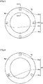
Fig. 3 is a view illustrating a first arrangement example of a load sensor element taken along a line III-III inFig. 2 . -
Fig. 4 is a view illustrating a second arrangement example of the load sensor element taken along the line III-III inFig. 2 . -
Fig. 5 is a sectional view illustrating aload sensor element 50 taken along a line X-X inFig. 3 . -
Fig. 6 is a front view illustratingload sensor element 50 inFig. 5 . -
Fig. 7 is a view illustrating a modification of a shape of a thin film pattern. -
Fig. 8 is a view illustrating a first improvement example of a structure of the load sensor element. -
Fig. 9 is a view illustrating a second improvement example of the structure of the load sensor element. -
Fig. 10 is a view illustrating a third improvement example of the structure of the load sensor element that is the improvement example inFig. 9 . -
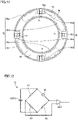
Fig. 11 is a view illustrating an example in which a processing unit that electrically processes output of the load sensor element is disposed in an outer-ring spacer. -
Fig. 12 is a circuit configuration diagram illustrating a configuration of an amplifier that detects a resistance change of the load sensor element. -
Fig. 13 is a view illustrating a configuration in which a preload (load) applied to a bearing is calculated from output of the load sensor element. -
Fig. 14 is a view illustrating a modification in which a mounting position of the load sensor element is fixed to an end face of a non-rotating wheel of the bearing. -
Fig. 15 is a view illustrating a modification in which a fixed position of the load sensor element is changed. -
Fig. 16 is a side view illustrating a modification in which a method for fixing the load sensor element is changed. -
Fig. 17 is an arrow view of a section taken along a line XVII-XVII inFig. 16 . -
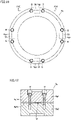
Fig. 18 is a sectional view illustrating an outer-ring spacer as an improvement example inFig. 16 . -
Fig. 19 is a sectional view illustrating an outer-ring spacer that is an improvement example inFig. 18 . -
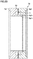
Fig. 20 is a sectional view illustrating an outer-ring spacer that is an improvement example inFig. 19 . - With reference to the drawings, an embodiment of the present invention will be described below. In the following drawings, the same or corresponding component is designated by the same reference numeral, and the overlapping description will be omitted.
-
Fig. 1 is a sectional diagram illustrating a schematic configuration of a spindle device according to an embodiment.Fig. 2 is an enlarged view of a left side main portion inFig. 1 .Fig. 2 mainly illustrates a bearingdevice 30. - For example, a
spindle device 1 inFig. 1 is used as a built-in motor type spindle device of a machine tool. In this case, amotor 40 is incorporated on one end side of amain shaft 4 supported byspindle device 1 for a machine tool spindle, and a cutting tool such as an end mill (not illustrated) is connected to the other end side. - With reference to
Figs. 1 and2 ,spindle device 1 includesbearings spacer 6 disposed adjacent tobearings motor 40, and abearing 16 disposed behind the motor.Main shaft 4 is rotatably supported by the plurality ofbearings housing 3 embedded in an inner diameter portion of anouter cylinder 2.Bearing 5a includes an inner ring 5ia, an outer ring 5ga, a rolling element Ta, and a retainer Rta.Bearing 5b includes an inner ring 5ib, an outer ring 5gb, a rolling element Tb, and a retainer Rtb.Spacer 6 includes an inner-ring spacer 6i and an outer-ring spacer 6g. - A load sensor element (pressure-sensitive sensor element) 50 is fixed to one end face 6ga of outer-
ring spacer 6g by adhesion or the like. In the case of fixing by the adhesion, an adhesive having excellent oil resistance and heat resistance is desirably used. - Inner ring 5ia of bearing 5a and inner ring 5ib of bearing 5b, which are separated in an axial direction, are fitted to
main shaft 4 in an interference fit state (press-fitted state). Inner-ring spacer 6i is disposed between inner rings 5ia, 5ib, and outer-ring spacer 6g is disposed between outer rings 5ga, 5gb. -
Bearing 5a is a rolling bearing in which a plurality of rolling elements Ta are disposed between inner ring 5ia and outer ring 5ga. These rolling elements Ta are spaced by retainer Rta.Bearing 5b is a rolling bearing in which a plurality of rolling elements Tb are disposed between inner ring 5ib and outer ring 5gb. These rolling elements Tb are spaced by retainer Rtb. -
Bearings device 30 inFig. 2 , and twobearings - In this case, a structure in which
main shaft 4 is supported by threebearings main shaft 4 is supported by at least three bearings may be used. - Single-
row rolling bearing 16 is a cylindrical roller bearing. A radial load and an axial load that act onspindle device 1 are supported bybearings spindle device 1 for the machine tool spindle is supported by single-row bearing 16 that is the cylindrical roller bearing. - A cooling medium passage G is formed in
housing 3.Bearings housing 3 andouter cylinder 2. - A lubricating oil supply passage is not required when a grease lubrication bearing is used as
bearings ring spacer 6g when lubrication of air oil or the like is required. At this point, the lubricating oil supply passage is not illustrated. - At the time of assembly, first, bearing 5a,
spacer 6, bearing 5b, andspacer 9 are sequentially inserted intomain shaft 4, and an initial preload is applied by tightening anut 10. Then,main shaft 4 to whichbearings housing 3 until a right side of outer ring 5gb of bearing 5b inFig. 2 hits astep 3a provided inhousing 3. Finally, afront lid 12 pushes outer ring 5ga ofleft bearing 5a to fixmain shaft 4 tohousing 3. - When
nut 10 is tightened, the force acts on the end face of inner ring 5ib of bearing 5b throughspacer 9, and inner ring 5ib is pushed toward inner-ring spacer 6i. This force is transmitted to inner ring 5ib, rolling element Tb, and outer ring 5gb to apply the preload between raceway surfaces of inner ring 5ib and outer ring 5gb and rolling element Tb, and also transmitted from outer ring 5gb to outer-ring spacer 6g. Pressing force acts on outer-ring spacer 6g from right outer ring 5gb, and force is also transmitted to loadsensor element 50. - This force is transmitted to outer ring 5ga, rolling element Ta, and inner ring 5ia in bearing 5a, and also applies the preload between the raceway surfaces of inner ring 5ia and outer ring 5ga of
left bearing 5a and rolling element Ta. The preload applied tobearings ring spacer 6g and inner-ring spacer 6i. - In single-row bearing 16 of
Fig. 1 , aninner ring 16a is positioned in the axial direction by acylindrical member 15 fitted to an outer periphery ofmain shaft 4 and an inner-ring retainer 19. Inner-ring retainer 19 is prevented from coming off by anut 20 screwed tomain shaft 4. Anouter ring 16b of bearing 16 is sandwiched between a positioningmember 21 fixed tocylindrical member 15 and a positioningmember 18 fixed to inner-ring retainer 19, and slides integrally withinner ring 16a with respect to anend member 17 in accordance with expansion and contraction ofmain shaft 4. -
Motor 40 that drivesmain shaft 4 is disposed at an intermediate position in the axial direction sandwiched betweenbearings space portion 22 formed betweenmain shaft 4 andouter cylinder 2. Arotor 14 ofmotor 40 is fixed tocylindrical member 15 fitted to the outer periphery ofmain shaft 4, and astator 13 ofmotor 40 is fixed to an inner peripheral portion ofouter cylinder 2. - The cooling medium passage for cooling
motor 40 is not illustrated here. -
Load sensor element 50 measuring the preload (load) of bearing 5 (5a, 5b) is mounted on a preload path ofspindle device 1. As illustrated inFig. 2 ,load sensor element 50 is fixed to end face 6ga of outer-ring spacer 6g by the adhesion or the like, abuts on the end face of outer ring 5ga of bearing 5a, and measures the preload applied to bearing 5 (5a, 5b). - When the output of
load sensor element 50 is observed at the time of assemblingspindle device 1, whether the preload is set in advance can be checked, and the number of assembling steps can be reduced. In addition, a preload amount increased by thermal expansion due to heat generation during operation can be known when the output ofload sensor element 50 is observed during the operation of the machine tool. When a preload change during the operation is observed, degradation of cutting performance and seizure of bearing 5 can be prevented in advance. - For example,
load sensor element 50 is a pressure-sensitive sensor including a thin film pattern (thin film resistor) that measures a load (preload) from a change in electric resistance, and is disposed on the path through which pressing force generating the preload is transmitted. -
Fig. 3 is a view illustrating a first arrangement example of the load sensor element taken along a line III-III inFig. 2 .Fig. 4 is a view illustrating a second arrangement example of the load sensor element taken along the line III-III inFig. 2 . InFigs. 3 and 4 , components unnecessary for the description are omitted. -
Fig. 3 illustrates the arrangement example ofload sensor element 50 mounted on end face 6ga of outer-ring spacer 6g. In this case,load sensor elements ring spacer 6g. - In the example of
Fig. 4 ,load sensor elements ring spacer 6g. - The number of
load sensor elements 50 is preferably at least 3 as long as the end face of outer ring 5ga can be uniformly pressed with good balance throughload sensor elements 50. In addition,load sensor elements 50 are preferably arranged at equal intervals on substantially the same circumference. - With reference to
Figs. 5 and 6 , the structure of the load sensor element will be described below.Fig. 5 is a sectional view illustratingload sensor element 50 taken along a line X-X inFig. 3 .Fig. 6 is a front view illustratingload sensor element 50 inFig. 5 . -
Load sensor element 50 includes asubstrate 51 having an insulating property, a thin film pattern (thin film resistor) 52 disposed onsubstrate 51 to change resistance with a change in surface pressure, anelectrode 53 connected tothin film pattern 52, and aprotective layer 54 having the insulating property protectingthin film pattern 52. Becauseprotective layer 54 is not formed onelectrode 53, wiring can be directly connected toelectrode 53. - For example, a ceramic material containing mainly zirconia (ZrO2) or alumina (Al2O3) is used for
substrate 51. The ceramic material has high rigidity and high insulating property, and can process the surface flatness ofsubstrate 51 with high accuracy, which is advantageous. For example, a thickness ofsubstrate 51 is preferably greater than or equal to 0.3 mm and less than or equal to 5 mm from the viewpoint of reducing the thickness ofload sensor element 50 and securing strength in a compression direction. - For example,
thin film pattern 52 is made of nickel chromium (NiCr) or chromium (Cr)-based material, and formed by vapor deposition, sputtering, or the like. For example, the thickness of the thin film pattern is less than or equal to 1 µm. In addition,protective layer 54 is made of an insulating material, and for example, a thin film of alumina (Al2O3) or silicon dioxide (SiO2) is formed by sputtering or the like. For example, the film thickness ofprotective layer 54 is about 2 µm. - The surface of
electrode 53 may be coated with a material such as copper, silver, or gold to facilitate soldering with the wiring. - An upper surface of
substrate 51 on whichthin film pattern 52 is formed may be polished so as to have flatness less than or equal to 1 µm. In addition, parallelism between the upper surface and the lower surface ofsubstrate 51 is preferably less than or equal to 1 µm. - As described above,
load sensor element 50 on whichthin film pattern 52 is formed is fixed to outer-ring spacer 6g by the adhesion or the like, so that it is easier to manufacture than directly forming the thin film pattern on outer-ring spacer 6g. - The load applied to outer-
ring spacer 6g is divided by the contact area ofload sensor element 50 abutting on the end face of outer ring 5ga of bearing 5a. In the above-described example, because the applied load is divided by the total area of eachload sensor element 50 abutting onprotective layer 54, the sensitivity of load detection is increased when the contact area withprotective layer 54 is reduced. However, the shape ofload sensor element 50 is set in consideration of each material physical property value ofload sensor element 50. In this case, the shape ofload sensor element 50 is rectangular. However, the shape is not limited thereto. -
Fig. 7 is a view illustrating a modification of the shape of the thin film pattern.Thin film pattern 52 has a U-shape in the example ofFig. 6 , but may be a continuous rectangular pattern as illustrated inFig. 7 , and the shape ofthin film pattern 52 is not limited thereto. When the continuous rectangular pattern is formed onsubstrate 51, a pressure-sensitive area is widened, and the load can be stably detected. -
Fig. 8 is a view illustrating a first improvement example of the structure of the load sensor element. InFig. 5 ,protective layer 54 is the thin film made of the insulating material and formed by vapor deposition or sputtering, but in aload sensor element 50A ofFig. 8 , for example, a plate material made of a ceramic material containing mainly zirconia (ZrO2) or alumina (Al2O3) is used as aprotective layer 54A.Protective layer 54A is bonded and fixed so as to coverthin film pattern 52 formed on the surface ofsubstrate 51 through anadhesive layer 55 made of the adhesive. For example, the thickness ofprotective layer 54A is about 0.3 mm to about 5 mm, which is the same as the thickness ofsubstrate 51. - When the plate material made of the insulating material is used as
protective layer 54A, manufacturing is facilitated as compared with the film formation ofprotective layer 54 by sputtering or the like. In addition, the insulation betweenthin film pattern 52 and outer ring 5ga can be further enhanced, and the load can be stably detected. In addition, becausethin film pattern 52 is pressed throughadhesive layer 55,adhesive layer 55 serves as a cushion layer and can uniformly pressthin film pattern 52, so that load detection accuracy is improved. -
Fig. 9 is a view illustrating a second improvement example of the structure of the load sensor element. InFigs. 5 and8 , the insulating material is used assubstrate 51. In aload sensor element 50B ofFig. 9 , a metal material is used as asubstrate 51A, and an insulatinglayer 58 is formed on the surface ofsubstrate 51A. For example, insulatinglayer 58 is made of the insulating material, and the thin film of alumina (Al2O3) or silicon dioxide (SiO2) is formed by sputtering or the like. For example, the thickness of insulatinglayer 58 is about 2 µm. - The same material as that of outer-
ring spacer 6g, for example, bearing steel (SUJ2) is used as the metal material ofsubstrate 51A. Carbon steel (S45C or the like) is used other than the bearing steel. These metal materials are cut to a certain size and subjected to a heat treatment, and thereafter, and a surface requiring processing accuracy is polished and lapped to be finished to have target flatness and surface roughness. For example, the flatness is set to less than or equal to 1 µm, and the surface roughness is set to less than or equal to Ra 0.1. - Then, after insulating
layer 58 is formed on one surface ofsubstrate 51A, thin film pattern (thin film resistor) 52 of which resistance changes due to the change in surface pressure andelectrode 53 connected tothin film pattern 52 are formed similarly toFig. 5 , andprotective layer 54 having the insulating property protectingthin film pattern 52 is further formed. Becauseprotective layer 54 is not formed onelectrode 53, the wiring can be directly connected toelectrode 53. - For example, the thin film of alumina (Al2O3) or silicon dioxide (SiO2) is formed as
protective layer 54 by sputtering or the like. For example, the film thickness is about 2 µm. - When the material of
substrate 51A is the metal material,substrate 51A is not cracked by a load, and reliability is improved. In addition, manufacture by formingthin film pattern 52 onsubstrate 51A made of small metal pieces is easier than manufacture by forming thethin film pattern 52 directly on the end face of outer-ring spacer 6g, and the manufacturing cost can be suppressed. -
Fig. 10 is a view illustrating a third improvement example of the structure of the load sensor element that is the improvement example inFig. 9 . InFig. 9 ,protective layer 54 is the thin film made of the insulating material and formed by vapor deposition or sputtering, but in aload sensor element 50C ofFig. 10 , for example, the plate material made of the ceramic material containing mainly zirconia (ZrO2) or alumina (Al2O3) is used asprotective layer 54A.Protective layer 54A is bonded and fixed so as to coverthin film pattern 52 formed on the surface ofsubstrate 51 throughadhesive layer 55 made of the adhesive. For example, the thickness ofprotective layer 54A is about 0.3 mm to about 5 mm, which is the same as the thickness ofsubstrate 51. - When the plate material made of the insulating material is used as
protective layer 54A, manufacturing is facilitated as compared with the film formation by sputtering or the like. In addition, the insulation fromthin film pattern 52 can be further enhanced, and the load can be stably detected. In addition, becausethin film pattern 52 is pressed throughadhesive layer 55,adhesive layer 55 serves as a cushion layer and can uniformly pressthin film pattern 52, so that load detection accuracy is improved. - As
protective layer 54A, the insulating film made of the insulating material may be formed on the plate material made of the metal material, and the side on which the insulating film is formed may face the side ofthin film pattern 52. In this case, cracking ofprotective layer 54 A can be prevented. -
Fig. 11 is a view illustrating an example in which a processing unit that electrically processes the output of the load sensor element is disposed in the outer-ring spacer. Load sensor element 50 (50a, 50b, 50c, 50d) fixed at equal intervals in the circumferential direction and aprocessing unit 70 ofload sensor element 50 are fixed to one end face 6ga of outer-ring spacer 6g. For example, processingunit 70 has a shape that does not interfere withload sensor element 50, and is manufactured so as to be thinner thanload sensor element 50 to prevent the contact with outer ring 5ga. - The output of
load sensor element 50 is connected to processingunit 70 bywiring 71. An amplifier 72 (72a, 72b, 72c, 72d) that detects and amplifies a resistance change of load sensor element 50 (50a, 50b, 50c, 50d) is mounted onprocessing unit 70, andprocessing unit 70 obtains an output value corresponding to the resistance change. In addition, anarithmetic unit 73 may be disposed inprocessing unit 70.Arithmetic unit 73 may process a resistance change amount of the plurality ofload sensor elements 50, convert the resistance change amount into a load applied to outer-ring spacer 6g, and output the load to the outside. -
Fig. 12 is a circuit configuration diagram illustrating a configuration of the amplifier that detects the resistance change of the load sensor element. -
Amplifier 72 inFig. 12 includes resistors R1 to R3 andload sensor element 50 that are connected to a DC power supply VSDC and a differential amplifier AMP Resistors R1 to R3 andload sensor element 50 configure a bridge circuit. Resistor R1 and resistor R2 are connected in series between a positive electrode and a negative electrode of DC power supply VSDC.Load sensor element 50 and resistor R3 are connected in series between the positive electrode and the negative electrode of DC power supply VSDC. One input node of differential amplifier AMP is connected to a connection node between resistor R1 and resistor R2. The other input node of differential amplifier AMP is connected to the connection node betweenload sensor element 50 and resistor R3. - With the bridge circuit configuration as illustrated in
Fig. 12 , the resistance change ofload sensor element 50 can be detected by differential amplifier AMP when the load changes. - The electric processing is performed near
load sensor element 50 by disposingamplifier 72 as illustrated inFig. 11 , so that an electric noise can be reduced. In addition, the number of wires to be drawn to the outside can be reduced, and bearingdevice 30 andspindle device 1 can be easily assembled. -
Fig. 13 is a view illustrating a configuration in which the preload (load) applied to the bearing is calculated from the output of the load sensor element. In this case, an example in which four load sensor elements are used will be described. - A calculation circuit in
Fig. 13 includesarithmetic unit 73 that performs arithmetic processing on an output value (Sa, Sb, Sc, Sd) of load sensor element 50 (50a, 50b, 50c, 50d) and astorage 74 that stores a relationship between the output value measured using outer-ring spacer 6g to whichload sensor element 50 is fixed in advance and the load or an approximate expression.Arithmetic unit 73 calculates the load from a sensor output representative value and data ofstorage 74.Arithmetic unit 73 andstorage 74 may be provided outsidebearing device 30 or inside processingunit 70. - The preload applied to outer-
ring spacer 6g is not uniform in the circumferential direction, and it is also assumed that a difference in output value depending on a detection location is generated due to the dimensional accuracy of outer-ring spacer 6g,housing 3,front lid 12,bearing 5, and the like. Whenmain shaft 4 rotates, it is also assumed that a circumferential load distribution fluctuates due to influence of a moment load applied tomain shaft 4 or movement of rolling elements Ta, Tb ofbearing 5. - For this reason, a maximum value, a minimum value, a difference between the maximum value and the minimum value, and the like are set as the sensor output representative value in addition to an addition value or an average value of the output values of load sensor elements 50 (50a, 50b, 50c, 50d), and the preload (load) is calculated.
- The output of the obtained preload (load) may be passed through a low-pass filter to reduce output fluctuation due to the passage of rolling elements Ta, Tb or the noise.
- During the assembly of bearing
device 30, fastening of a preload adjusting component, for example,nut 10, or mounting of a fixing screw offront lid 12 can be also adjusted while viewing the preload. - In addition, when bearing
device 30 is mounted onspindle device 1 to rotatemain shaft 4 at a high speed bymotor 40, it is assumed that bearing 5 generates heat due to damage ofbearing 5, the preload becomes excessive, andbearing 5 burns out. However, when the preload is calculated and monitored fromload sensor element 50, an avoidance measure can be taken so as not to burn outbearing 5. - For example, when the preload measured by
load sensor element 50 exceeds a reference value set in advance, bearing 5 is determined to be abnormal, and measures such as lowering the rotational speed ofmain shaft 4, increasing the circulation amount of the cooling medium, and reducing the machining load are taken to prevent burning ofbearing 5. - In addition, because
load sensor element 50 is fixed to outer-ring spacer 6g located on the transmission path of the force generating the preload, the initial preload of bearing 5 (5a, 5b) can be grasped from the output ofload sensor element 50 whenspindle device 1 is assembled, and the fastening amount ofnut 10 can be adjusted while viewing the preload amount. -
Arithmetic unit 73 may calculate a moment load applied tomain shaft 4 from the difference between outputs ofload sensor elements 50 facing each other at 180 degrees. For example, in the arrangement of load sensor element 50 (50a, 50b, 50c, 50d) inFig. 11 , the magnitude and direction of the moment load in the vertical direction ofmain shaft 4 can be calculated from the difference betweenload sensor elements main shaft 4 can also be calculated from the difference betweenload sensor elements - For example, when a metal workpiece is cut with a cutting tool such as an end mill fixed to the other end side of
spindle device 1, the load and the load direction applied to the cutting tool can be grasped from the moment load. In addition, it is also possible to detect that the cutting tool collides with the metal workpiece from the moment load. - In order to increase the reliability of an abnormal diagnosis with an increase in the preload (load), it is also possible to comprehensively determine by further considering outputs of other sensors such as a temperature sensor, a heat flux sensor, and an acceleration sensor. For example, when the heat flux sensor is fixed to a non-rotating member (for example, outer-
ring spacer 6g) nearbearing 5 and disposed to face the rotating member (for example, main shaft 4), a sign of temperature rise due to the seizure of bearing 5 can be detected early. -
Fig. 14 is a view illustrating a modification in which the mounting position of the load sensor element is fixed to the end face of the non-rotating wheel of the bearing. - For example,
load sensor element 50 is fixed to the end face of outer ring 5ga of bearing 5a by the adhesion or the like. When the plurality ofload sensor elements 50 are fixed, it is desirable to fix the load sensor elements using a bonding jig (not illustrated) or the like such that the heights of the load sensor elements become uniform. Even in this structure, processingunit 70 may be provided on the end face of outer ring 5ga. In this case, processingunit 70 is preferably mounted integrally with a fixed ring (outer ring 5ga). -
Load sensor element 50 is fixed to the end face ofbearing 5, so that a load detection unit can be compactly mounted. -
Fig. 15 is a view illustrating a modification in which the fixed position of the load sensor element is changed. InFig. 15 ,load sensor element 50 is fixed to an end face 6gla of one outer-ring spacer 6g1 obtained by dividing outer-ring spacer 6g into two in the axial direction, and an end face 6g2a of the other outer-ring spacer 6g2 abuts onload sensor element 50. - Because the side view in which load
sensor element 50 is mounted is the same as that inFig. 3, 4 , or11 , the description thereof is omitted. - End face 6gla of outer-ring spacer 6g1 to which
load sensor element 50 is fixed and end face 6g2a of outer-ring spacer 6g2 that pressesload sensor element 50 need to be processed such that flatness and surface roughness and the parallelism of these end faces 6g1a, 6g2a are less than or equal to reference values, and each of outer-ring spacers 6g1, 6g2 can be processed with high accuracy. - In end face 6g2a of outer-ring spacer 6g2, a convex surface (not illustrated) may be provided such that the convex surface and
load sensor element 50 abut on each other. In addition, in end face 6g1a of outer-ring spacer 6g1, the convex surface (not illustrated) may be provided, andload sensor element 50 may be fixed to the convex surface. - Furthermore, outer-ring spacers 6g1, 6g2 divided into two may be aligned by pins (not illustrated) so as not to be separated.
- In this case, the area for which the machining accuracy is required can be reduced, so that the machining time can be shortened while the machining is facilitated.
- Alternatively, an intermediate layer (cushion layer) (not illustrated) may be inserted between
load sensor element 50 and end face 6g2a of outer-ring spacer 6g2 to pressload sensor element 50. - For example, a coating thin film of a metal material (for example, aluminum, copper, or a metal alloy) having lower rigidity (longitudinal elastic modulus) than the material of outer-
ring spacer 6g, a resin material (for example, a fluorine-based resin), or the like can be used as the material of the intermediate layer. - The intermediate layer is deformed by the pressing through the intermediate layer having lower rigidity than outer-
ring spacer 6g, andload sensor element 50 can be uniformly and stably pressed. - In addition, with the configuration in which load
sensor element 50 is pressed through the intermediate layer, the processing accuracy (surface roughness, flatness, and the like) of the end face of outer-ring spacer 6g can be reduced as compared with the case where the intermediate layer is not used, and the processing is facilitated. -
Load sensor element 50 andprocessing unit 70 or a part ofprocessing unit 70 may be integrally mounted. -
Fig. 16 is a side view illustrating a modification in which a method for fixing the load sensor element is changed.Fig. 17 is an arrow view of a section taken along a line XVII-XVII inFig. 16 . -
Load sensor element 50 is disposed between the two divided outer-ring spacers 6g1, 6g2, and the preload is applied to loadsensor element 50 by fastening outer-ring spacers 6g1, 6g2 with a screw B. Althoughload sensor element 50 can be fixed without applying the adhesive to the contact surfaces of outer-ring spacers 6g1, 6g2 andload sensor element 50, the adhesive may be used in combination. - End faces 6g1a, 6g2a of outer-ring spacers 6g1, 6g2 on which
load sensor element 50 abuts have a structure in which protrusions are not provided on end faces 6gla, 6g2a to easily obtain surface accuracy by flat grinding such that the processing can be performed with high accuracy in surface roughness and flatness. - When being provided on the outer diameter surface of outer-
ring spacer 6g, a planarizing portion 6gb can be used as a mark of the arrangement position ofload sensor element 50. - When the preload is applied to load
sensor element 50, a dead zone is eliminated in the output ofload sensor element 50, and the reduction of hysteresis and the improvement of linearity can be expected. -
Fig. 18 is a sectional view illustrating the outer-ring spacer as an improvement example ofFig. 16 . - When bearing 5 for air-oil lubrication is used, a nozzle for air oil is processed in outer-
ring spacer 6g, and the air oil is injected from the nozzle towardbearing 5. An oil seal member 6gh may be disposed between outer-ring spacers 6g1, 6g2 such that the air oil does not leak from a gap of divided inter-outer-ring spacer 6g to the side ofwiring 71. Oil seal member 6gh may be made of a metal material. However, preferably oil seal member 6gh is made of a resin material so as to be able to be pressed and deformed at outer-ring spacers 6g1, 6g2 to prevent the formation of the gap. - When
load sensor element 50 is sandwiched between two divided outer-ring spacers 6g1, 6g2 and fastened with screw B, a jig (not illustrated) is preferably used when it is difficult to align outer-ring spacers 6g1, 6g2. For example, when outer-ring spacer 6g is inserted into the cylindrical jig inner diameter portion to perform the assembly, the centering is easy. -
Fig. 19 is a sectional view illustrating the outer-ring spacer as an improvement example ofFig. 18 . - As illustrated in
Fig. 19 , steps 6glm, 6g2m are provided in the inner diameter portions of outer-ring spacers 6g1, 6g2, and an oil seal member 6gk is disposed so as to be fitted to the steps. - Oil seal member 6gk enables alignment of outer-ring spacer 6g1, 6g2, and the jig can be omitted.
-
Fig. 20 is a sectional view illustrating the outer-ring spacer as an improvement example ofFig. 19 . - As illustrated in
Fig. 20 , a flange 6g1n is provided on the inner diameter side of outer-ring spacer 6g1, a step 6g2n into which flange 6g1n is fitted is provided on the inner diameter surface of the other outer-ring spacer 6g2, and flange 6g1n and step 6g2n are fitted. Thus, the alignment of outer-ring spacer 6g1, 6g2 can be performed. In addition, leakage of the air oil can be prevented to have a sealing function. - In this structure, the oil seal member is not required, the number of components can be reduced, and assemblability is improved.
- As described in the above embodiment, in the bearing device of the embodiment, load sensor element 50 (pressure-sensitive sensor element) is disposed on outer-
ring spacer 6g on the load path in which the preload (load) is applied to the bearing or on the end face ofbearing 5. Load sensor element 50 (pressure-sensitive sensor element) on which the thin film resistor capable of measuring the load is formed is fixed by the adhesion or the like in the circumferential direction of outer-ring spacer 6g, andload sensor element 50 has a structure in which the pressing is performed through the member abutting onload sensor element 50. Thus, the manufacturing can be simplified as compared with the case where the thin film sensor that detects the load is directly formed on the metal component such as the outer-ring spacer. - Finally, the embodiment will be summarized again with reference to the drawings.
- The present disclosure relates to bearing
device 30.Bearing device 30 includes at least onebearing 5 including the rolling element and the raceway surface to supportmain shaft 4, the member (6 or 5ga) disposed on the path through which the pressing force generating the preload is transmitted between the rolling element and the raceway surface, and at least oneload sensor element 50 fixed to the member (6 or 5ga) to be capable of measuring the pressing force. At least oneload sensor element 50 is a chip component includingthin film pattern 52 of which resistance changes according to the pressing force andprotective layer 54 that insulates and protectsthin film pattern 52. -
Load sensor element 50 is small in size, and the plurality ofload sensor elements 50 can be stably manufactured at once. For this reason, the manufacturing can be simplified as compared with the case where the thin film sensor that detects the load is directly formed on the metal component such as the outer-ring spacer. Consequently, the improvement in reliability and the reduction in manufacturing cost can be expected. - Preferably, the pressing force is applied by the load in the direction along
main shaft 4. As illustrated inFig. 3 or 4 , at least oneload sensor element 50 is the plurality ofload sensor elements main shaft 4. - As described above, the plurality of
load sensor elements - More preferably, the bearing device further includes
arithmetic unit 73 that calculates the magnitude and direction of the moment load in the direction orthogonal tomain shaft 4 using the outputs of the plurality ofload sensor elements 50a to 50d. - For example, the magnitude and direction of the load applied to the cutting tool during machining of the workpiece with the cutting tool such as an end mill can be grasped with such a configuration.
- Preferably, as illustrated in
Figs. 1 and2 , at least onebearing 5 is the plurality ofbearings load sensor element 50 is fixed is non-rotation-side outer-ring spacer 6g inserted between twobearings load sensor element 50 is fixed to end face 6ga of the spacer, and abuts on the fixed ring (outer ring 5ga) of one of twobearings - The structure in which the spacer is arranged between the plurality of bearings is common for the spindle devices. Thus, the bearing device of the embodiment is easily applied to the spindle device.
- Preferably, as illustrated in
Fig. 14 , the member to whichload sensor element 50 is fixed is the fixed ring (outer ring 5ga) of at least one bearing. At least oneload sensor element 50 is fixed to the end face of the fixed ring (outer ring 5ga) and abuts on the end face ofspacer 6 disposed adjacent to the fixed ring (outer ring 5ga) to transmit the pressing force. - In this manner, the load sensor element may be fixed to the bearing side instead of the spacer.
Load sensor element 50 is fixed to the end face ofbearing 5, so that the load detection unit can be compactly mounted. - Preferably, the member to which
load sensor element 50 is fixed is first spacer 6g1 obtained by dividingspacer 6 disposed adjacent to at least one bearing into first spacer 6g1 and second spacer 6g2. At least oneload sensor element 50 is fixed to the end face of first spacer 6g1 and abuts on the end face of second spacer 6g2 to transmit the pressing force. - As described above, when the spacer is divided into two to sandwich
load sensor element 50 therebetween, the spacer can be carried whileload sensor element 50 is set in the spacer at a manufacturing stage. - Preferably, as illustrated in
Fig. 11 , bearingdevice 30 further includes processingunit 70 that is disposed near at least oneload sensor element 50 to process the output of at least oneload sensor element 50. Processingunit 70 includesamplifier 72 that detects and amplifies the resistance change of at least oneload sensor element 50. - Preferably, bearing
device 30 further includes processingunit 70 that is disposed near at least one load sensor element to process the output of at least oneload sensor element 50. As illustrated inFig. 13 , at least oneload sensor element 50 is the plurality ofload sensor elements 50a to 50d. Processingunit 70 includes the plurality ofamplifiers 72a to 72d that process outputs of the plurality ofload sensor elements 50a to 50d,arithmetic unit 73, andstorage 74.Arithmetic unit 73 calculates the load from the sensor output representative value including at least one of the addition value, the average value, the maximum value, the minimum value, and the difference between the maximum value and the minimum value of the output values obtained by the plurality ofamplifiers 72a to 72d, the relationship between the load stored in advance instorage 74 and the sensor output representative value, or the approximate expression of the relationship. - Preferably, as illustrated in
Figs. 16 and 17 , the member to whichload sensor element 50 is fixed is any one of first outer-ring spacer 6g1 and second outer-ring spacer 6g2 in which the spacer disposed adjacent to at least one bearing is divided into two. First outer-ring spacer 6g1 and second outer-ring spacer 6g2 sandwich at least oneload sensor element 50. First outer-ring spacer 6g1 and second outer-ring spacer 6g2 are fastened by screw B, and the pressing force by the fastening force of screw B is applied in advance to at least oneload sensor element 50. - When the preload is applied to load
sensor element 50, the dead zone is eliminated in the output ofload sensor element 50, and the reduction of hysteresis and the improvement of linearity can be expected. - Preferably, as illustrated in
Figs. 16 and 17 , the member to whichload sensor element 50 is fixed is any one of first outer-ring spacer 6g1 and second outer-ring spacer 6g2 in which the spacer disposed adjacent to at least one bearing is divided into two. First outer-ring spacer 6g1 and second outer-ring spacer 6g2 sandwich at least oneload sensor element 50. End faces 6gla, 6g2a, which are sandwiching surfaces sandwiching at least oneload sensor element 50 of first outer-ring spacer 6g1 and second outer-ring spacer 6g2, are flat surfaces without protrusions. - Because the end face is the flat surface without the protrusion as described above, the surface accuracy can be easily obtained by flat grinding, and the processing with high accuracy of surface roughness and accuracy of flatness can be performed on the installation surface and the abutment surface of
load sensor element 50. - More preferably, as illustrated in
Figs. 18 and19 , bearingdevice 30 further includes oil seal members 6gh, 6gk disposed between first outer-ring spacer 6g1 and second outer-ring spacer 6g2 of the spacer. - Preferably, as illustrated in
Fig. 20 , the member to whichload sensor element 50 is fixed is any one of first spacer 6g1 and second spacer 6g2 in which the spacer disposed adjacent to at least one bearing is divided into two. First spacer 6g1 and second spacer 6g2 sandwich at least oneload sensor element 50. Flange 6gln, which is a convex portion in which the position of second spacer 6g2 is limited, is formed in first spacer 6g1. Flange 6g1n is fitted into step 6g2n, which is a concave portion of second spacer 6g2, to regulate the position of second spacer 6g2. - Thus, the alignment of outer-ring spacer 6g1, 6g2 can be performed. In addition, the leakage of the air oil can be prevented to have the sealing function. In this structure, the oil seal member is not required, the number of components can be reduced, and the assemblability is improved.
- In another aspect, the present disclosure relates to
spindle device 1 including bearingdevice 30 described in any one of the above. - In still another aspect, the present disclosure relates to bearing 5a. As illustrated in
Fig. 14 , bearing 5a includes rolling element Ta, inner ring 5ia, outer ring 5ga, and at least oneload sensor element 50 that is disposed on the end face of the fixed ring (outer ring 5ga) in inner ring 5ia and outer ring 5ga to be capable of measuring the pressing force generating the preload between rolling element Ta and the raceway surface of the fixed ring. As illustrated inFig. 6 and the like, at least oneload sensor element 50 is a chip component includingthin film pattern 52 of which resistance changes according to the pressing force andprotective layer 54 that insulates and protectsthin film pattern 52. - Preferably, bearing 5a further includes processing
unit 70 that processes the output of the at least one load sensor element. Processingunit 70 is integrally mounted on the fixed ring (outer ring 5ga). - In still another aspect, the present disclosure relates to spacer 6 disposed adjacent to bearing 5 including the rolling element and the raceway surface.
Spacer 6 includes outer-ring spacer 6g that is the member to which the pressing force generating the preload between the rolling element and the raceway surface is transmitted, and at least oneload sensor element 50 that is fixed to outer-ring spacer 6g to be capable of measuring the pressing force. As illustrated inFigs. 5 to 10 , at least oneload sensor element 50 is the chip component includingthin film pattern 52 of which resistance changes according to the pressing force andprotective layer 54 that insulates and protectsthin film pattern 52. - Preferably, as illustrated in
Fig. 11 ,spacer 6 further includes processingunit 70 that is integrally mounted on the member, to which the pressing force generating the preload is transmitted, to process the output of at least oneload sensor element 50. - Preferably, as illustrated in
Fig. 15 , the member to whichload sensor element 50 is fixed is first spacer 6g1 obtained by dividing outer-ring spacer 6g into first spacer 6g1 and second spacer 6g2. At least oneload sensor element 50 is fixed to end face 6g1a of first spacer 6g1, and abuts on end face 6g2a of second spacer 6g2 to transmit the pressing force. - Preferably, as illustrated in
Figs. 16 and 17 , first spacer 6g1 and second spacer 6g2 sandwich at least oneload sensor element 50. First spacer 6g1 and second spacer 6g2 are fastened by screw B. The pressing force by fastening force of screw B is applied in advance to at least oneload sensor element 50. - More preferably, as illustrated in
Figs. 18 and19 , outer-ring spacer 6g further includes oil seal members 6gh, 6gk disposed between first spacer 6g1 and second spacer 6g2. - More preferably, as illustrated in
Fig. 19 , the step that enables the alignment of first spacer 6g1 and second spacer 6g2 is formed on the inner diameter portion side of first spacer 6g1 and second spacer 6g2 by fitting with oil seal member 6gk. - With such a configuration, outer-ring spacers 6g1, 6g2 can be aligned by oil seal member 6gk, and the jig for aligning outer-ring spacers 6g1, 6g2 can be omitted.
- It should be considered that the disclosed embodiment is an example in all respects and not restrictive. The scope of the present invention is defined by not the description of the embodiment, but the claims, and it is intended that all changes within the meaning and scope of the claims are included in the present invention.
- 1: spindle device, 2: outer cylinder, 3: housing, 3a, 6g2n: step, 4: main shaft, 5, 5a, 5b, 16: bearing, 5ga, 5gb, 16b: outer ring, 5ia, 5ib, 16a: inner ring, 6, 9: spacer, 6g, 6g1, 6g2: outer-ring spacer, 6gla, 6g2a, 6ga: end face, 6glm, 6g2m: step, 6gln: flange, 6gb: planarizing portion, 6gh, 6gk: oil seal member, 6i: inner-ring spacer, 10, 20: nut, 12: front lid, 13: stator, 14: rotor, 15: cylindrical member, 17: end member, 18, 21: positioning member, 19: inner-ring retainer, 22: space portion, 27, 73: arithmetic unit, 28, 74: storage, 30: bearing device, 40: motor, 50, 50A, 50B, 50a, 50b, 50c, 50d: load sensor element, 51, 51A: substrate, 52: thin film pattern, 53: electrode, 54, 54A: protective layer, 55: adhesive layer, 58: insulating layer, 70: processing unit, 71: wiring, 72, 72a, 72d: amplifier, AMP: differential amplifier, B: screw, G: cooling medium passage, R1, R2, R3: resistor, Rta, Rtb: retainer, Ta, Tb: rolling element, VSDC: power supply
Claims (15)
- A bearing device comprising:at least one bearing that includes a rolling element and a raceway surface to support a shaft;a member disposed on a path through which a pressing force generating a preload between the rolling element and the raceway surface is transmitted; andat least one load sensor element fixed to the member to measure the pressing force, whereinthe at least one load sensor element includes a thin film pattern of which resistance changes according to the pressing force and a protective layer that insulates and protects the thin film pattern.
- The bearing device according to claim 1, whereinthe pressing force is applied by a load in a direction along the shaft, andthe at least one load sensor element is a plurality of load sensor elements arranged at equal intervals on a circumference in a plane intersecting the direction along the shaft.
- The bearing device according to claim 2, further comprising an arithmetic unit that calculates magnitude and a direction of a moment load in a direction orthogonal to the shaft, using outputs of the plurality of load sensor elements.
- The bearing device according to claim 1 or 2, whereinthe at least one bearing is a plurality of bearings,the member is a non-rotating-side spacer inserted between two bearings among the plurality of bearings, andthe at least one load sensor element is fixed to an end face of the spacer, and abuts on a fixed ring of one of the two bearings to transmit the pressing force.
- The bearing device according to claim 1 or 2, whereinthe member is a fixed ring of the at least one bearing, andthe at least one load sensor element is fixed to an end face of the fixed ring, and abuts on an end face of a spacer disposed adjacent to the fixed ring to transmit the pressing force.
- The bearing device according to claim 1 or 2, whereinthe member is a first spacer obtained by dividing a spacer disposed adjacent to the at least one bearing into the first spacer and a second spacer, andthe at least one load sensor element is fixed to an end face of the first spacer, and abuts on an end face of the second spacer to transmit the pressing force.
- The bearing device according to claim 1 or 2, further comprising a processing unit that is disposed near the at least one load sensor element to process output of the at least one load sensor element, wherein
the processing unit includes an amplifier that detects and amplifies a resistance change of the at least one load sensor element. - The bearing device according to claim 1, further comprising a processing unit that is disposed near the at least one load sensor element to process output of the at least one load sensor element, whereinthe at least one load sensor element is a plurality of load sensor elements,the processing unit includesa plurality of amplifiers that process outputs of the plurality of load sensor elements,an arithmetic unit, anda storage, andthe arithmetic unit calculates a load from a sensor output representative value including at least one of an addition value, an average value, a maximum value, a minimum value, and a difference between the maximum value and the minimum value of output values obtained by the plurality of amplifiers; a relationship between a load stored in advance in the storage and the sensor output representative value; or an approximate expression of the relationship.
- The bearing device according to claim 1, whereinthe member is one of a first outer-ring spacer and a second outer-ring spacer that are obtained by dividing a spacer disposed adjacent to the at least one bearing into two,the first outer-ring spacer and the second outer-ring spacer sandwich the at least one load sensor element,the first outer-ring spacer and the second outer-ring spacer are fastened by a screw, andpressing force by fastening force of the screw is applied in advance to the at least one load sensor element.
- The bearing device according to claim 1, whereinthe member is one of a first spacer and a second spacer that are obtained by dividing a spacer disposed adjacent to the at least one bearing into two,the first spacer and the second spacer sandwich the at least one load sensor element, anda convex portion in which a position of the second spacer is limited is formed in the first spacer.
- A spindle device comprising the bearing device according to any one of claims 1 to 10.
- A bearing comprising:a rolling element;an inner ring;an outer ring; andat least one load sensor element that is disposed on an end face of a fixed ring of the inner ring and the outer ring to measure pressing force generating a preload between the rolling element and a raceway surface of the fixed ring, whereinthe at least one load sensor element includes a thin film pattern of which resistance changes according to the pressing force and a protective layer that insulates and protects the thin film pattern.
- The bearing according to claim 12, further comprising a processing unit that processes output of the at least one load sensor element, wherein
the processing unit is integrally mounted on the fixed ring. - A spacer disposed adjacent to a bearing including a rolling element and a raceway surface, the spacer comprising:a member to which pressing force generating a preload between the rolling element and the raceway surface is transmitted; andat least one load sensor element that is fixed to the member to measure the pressing force, whereinthe at least one load sensor element includes a thin film pattern of which resistance changes according to the pressing force and a protective layer that insulates and protects the thin film pattern.
- The spacer according to claim 14, further comprising a processing unit that is integrally mounted on the member to process output of the at least one load sensor element.
Applications Claiming Priority (2)
| Application Number | Priority Date | Filing Date | Title |
|---|---|---|---|
| JP2019231814A JP7411405B2 (en) | 2019-12-23 | 2019-12-23 | Bearing devices, spindle devices, bearings, and spacers |
| PCT/JP2020/045593 WO2021131662A1 (en) | 2019-12-23 | 2020-12-08 | Bearing device, spindle device, bearing and spacer |
Publications (3)
| Publication Number | Publication Date |
|---|---|
| EP4083456A1 true EP4083456A1 (en) | 2022-11-02 |
| EP4083456A4 EP4083456A4 (en) | 2024-03-27 |
| EP4083456B1 EP4083456B1 (en) | 2025-10-22 |
Family
ID=76541060
Family Applications (1)
| Application Number | Title | Priority Date | Filing Date |
|---|---|---|---|
| EP20904819.8A Active EP4083456B1 (en) | 2019-12-23 | 2020-12-08 | Bearing device and spindle device |
Country Status (5)
| Country | Link |
|---|---|
| US (1) | US12196257B2 (en) |
| EP (1) | EP4083456B1 (en) |
| JP (1) | JP7411405B2 (en) |
| CN (1) | CN114867998B (en) |
| WO (1) | WO2021131662A1 (en) |
Families Citing this family (5)
| Publication number | Priority date | Publication date | Assignee | Title |
|---|---|---|---|---|
| JP7724628B2 (en) * | 2021-03-30 | 2025-08-18 | Ntn株式会社 | Bearing device, spindle device and spacer |
| JP7766442B2 (en) * | 2021-09-27 | 2025-11-10 | Ntn株式会社 | Bearing device and spindle device |
| CN118435248A (en) * | 2021-12-23 | 2024-08-02 | 柯尼卡美能达株式会社 | Information processing system, behavior quantization program, and behavior quantization method |
| CN119308937A (en) * | 2024-10-10 | 2025-01-14 | 珠海格力电器股份有限公司 | Magnetic levitation rotating machinery |
| DE102025125952A1 (en) * | 2025-07-03 | 2026-05-21 | Zf Friedrichshafen Ag | Electric machine and electric axle drive |
Family Cites Families (27)
| Publication number | Priority date | Publication date | Assignee | Title |
|---|---|---|---|---|
| JPS60227140A (en) * | 1984-04-25 | 1985-11-12 | Yamato Scale Co Ltd | Load cell |
| JP3689962B2 (en) * | 1996-02-26 | 2005-08-31 | 日本精工株式会社 | Double row rolling bearing unit |
| US6000855A (en) | 1996-02-26 | 1999-12-14 | Nsk Ltd. | Outer ring spacer for double row rolling bearing unit |
| JP4527236B2 (en) * | 2000-03-30 | 2010-08-18 | トヨタ自動車株式会社 | Thin film sensor |
| US6802208B2 (en) * | 2002-03-04 | 2004-10-12 | Delphi Technologies, Inc. | Vehicle wheel bearing and method for controlling a vehicle |
| CN100442041C (en) * | 2003-05-22 | 2008-12-10 | 日本精工株式会社 | Load measuring device for rolling bearing unit and load measuring rolling bearing unit |
| JP2005265175A (en) * | 2004-02-18 | 2005-09-29 | Ntn Corp | Bearing device for wheel |
| EP1717467B1 (en) | 2004-02-18 | 2010-10-27 | NTN Corporation | Bearing device for wheel |
| US7628540B2 (en) * | 2004-02-18 | 2009-12-08 | Ntn Corporation | Bearing device for wheel |
| US7497131B2 (en) * | 2004-11-22 | 2009-03-03 | Jtekt Corporation | Sensor-mounted roller bearing apparatus |
| US7665372B2 (en) | 2005-04-27 | 2010-02-23 | Jtekt Corporation | Rolling bearing device with sensor and strain sensor |
| JP2007032705A (en) * | 2005-07-27 | 2007-02-08 | Jtekt Corp | Rolling bearing device with sensor and strain sensor |
| JP2006307935A (en) * | 2005-04-27 | 2006-11-09 | Jtekt Corp | Rolling bearing device with sensor |
| JP2007271005A (en) * | 2006-03-31 | 2007-10-18 | Jtekt Corp | Rolling bearing device with sensor |
| JP2009036312A (en) * | 2007-08-02 | 2009-02-19 | Ntn Corp | Bearing device |
| JP2008286219A (en) | 2007-05-15 | 2008-11-27 | Ntn Corp | Bearing device and bearing preload detecting device |
| JP5140853B2 (en) * | 2007-05-31 | 2013-02-13 | 本田技研工業株式会社 | Axial load measuring device |
| JP2009115284A (en) * | 2007-11-09 | 2009-05-28 | Ntn Corp | Bearing device |
| KR20100075578A (en) * | 2007-11-09 | 2010-07-02 | 엔티엔 가부시키가이샤 | Bearing device |
| DE102009005888A1 (en) * | 2009-01-23 | 2010-07-29 | Robert Bosch Gmbh | Device for determining force acting on outer bearing ring of e.g. axial bearing, has force sensor coupled with component to determine force, and spring element providing pretensioning force between force sensor and component |
| JP2010180982A (en) * | 2009-02-06 | 2010-08-19 | Nippon Soken Inc | Rotary shaft supporting structure and controller for engine |
| WO2010139350A1 (en) * | 2009-06-05 | 2010-12-09 | Skf Bv | Load-measuring bearing unit |
| JP2011167799A (en) * | 2010-02-18 | 2011-09-01 | Ntn Corp | Main spindle device |
| JP5589793B2 (en) * | 2010-11-18 | 2014-09-17 | 日本精工株式会社 | Load sensor, sensor-equipped hub unit and vehicle |
| DE102015217139B4 (en) * | 2015-09-08 | 2017-03-30 | Schaeffler Technologies AG & Co. KG | roller bearing assembly |
| TWM552594U (en) * | 2017-07-04 | 2017-12-01 | Buffalo Machinery Company Ltd | Bearing monitoring device |
| JP7165021B2 (en) * | 2018-10-09 | 2022-11-02 | Ntn株式会社 | bearing device |
-
2019
- 2019-12-23 JP JP2019231814A patent/JP7411405B2/en active Active
-
2020
- 2020-12-08 CN CN202080089172.4A patent/CN114867998B/en active Active
- 2020-12-08 US US17/787,047 patent/US12196257B2/en active Active
- 2020-12-08 WO PCT/JP2020/045593 patent/WO2021131662A1/en not_active Ceased
- 2020-12-08 EP EP20904819.8A patent/EP4083456B1/en active Active
Also Published As
| Publication number | Publication date |
|---|---|
| JP2021099282A (en) | 2021-07-01 |
| US12196257B2 (en) | 2025-01-14 |
| CN114867998A (en) | 2022-08-05 |
| EP4083456A4 (en) | 2024-03-27 |
| CN114867998B (en) | 2025-10-17 |
| WO2021131662A1 (en) | 2021-07-01 |
| US20230027711A1 (en) | 2023-01-26 |
| EP4083456B1 (en) | 2025-10-22 |
| JP7411405B2 (en) | 2024-01-11 |
Similar Documents
| Publication | Publication Date | Title |
|---|---|---|
| US12196257B2 (en) | Bearing device, spindle device, bearing and spacer | |
| JP7206315B2 (en) | Bearing and spindle devices | |
| KR102688195B1 (en) | Preload sensors, bearing units, bearings and spacers | |
| JP7570205B2 (en) | Bearing device | |
| EP2964967A1 (en) | Method of setting bearing preload | |
| CN113453826B (en) | Bearing assembly and spindle assembly | |
| JP7713792B2 (en) | Bearing device and spindle device | |
| KR20100075578A (en) | Bearing device | |
| JP2020060227A (en) | Bearing device | |
| JP7724628B2 (en) | Bearing device, spindle device and spacer | |
| CN112823271B (en) | Bearing unit and preload sensor | |
| WO2020166542A1 (en) | Bearing device and spindle device | |
| JP2024039154A (en) | Bearing devices and spindle devices | |
| JP7766442B2 (en) | Bearing device and spindle device | |
| JP2026023001A (en) | Rolling bearing with sensor | |
| JP2009115284A (en) | Bearing device | |
| JP2024110470A (en) | Bearing device and spindle device | |
| JP2009127765A (en) | Bearing device | |
| TW202434806A (en) | Bearing device with sensor and spindle device for machine tool | |
| WO2024080215A1 (en) | Bearing device and spindle device with bearing device | |
| JP2008275107A (en) | Method for manufacturing rolling bearing device with sensor |
Legal Events
| Date | Code | Title | Description |
|---|---|---|---|
| STAA | Information on the status of an ep patent application or granted ep patent |
Free format text: STATUS: THE INTERNATIONAL PUBLICATION HAS BEEN MADE |
|
| PUAI | Public reference made under article 153(3) epc to a published international application that has entered the european phase |
Free format text: ORIGINAL CODE: 0009012 |
|
| STAA | Information on the status of an ep patent application or granted ep patent |
Free format text: STATUS: REQUEST FOR EXAMINATION WAS MADE |
|
| 17P | Request for examination filed |
Effective date: 20220714 |
|
| AK | Designated contracting states |
Kind code of ref document: A1 Designated state(s): AL AT BE BG CH CY CZ DE DK EE ES FI FR GB GR HR HU IE IS IT LI LT LU LV MC MK MT NL NO PL PT RO RS SE SI SK SM TR |
|
| DAV | Request for validation of the european patent (deleted) | ||
| DAX | Request for extension of the european patent (deleted) | ||
| RIC1 | Information provided on ipc code assigned before grant |
Ipc: G01L 5/00 20060101ALI20231127BHEP Ipc: F16C 41/00 20060101ALI20231127BHEP Ipc: F16C 35/12 20060101ALI20231127BHEP Ipc: F16C 35/077 20060101ALI20231127BHEP Ipc: F16C 25/08 20060101AFI20231127BHEP |
|
| A4 | Supplementary search report drawn up and despatched |
Effective date: 20240222 |
|
| RIC1 | Information provided on ipc code assigned before grant |
Ipc: G01L 5/00 20060101ALI20240216BHEP Ipc: F16C 41/00 20060101ALI20240216BHEP Ipc: F16C 35/12 20060101ALI20240216BHEP Ipc: F16C 35/077 20060101ALI20240216BHEP Ipc: F16C 25/08 20060101AFI20240216BHEP |
|
| STAA | Information on the status of an ep patent application or granted ep patent |
Free format text: STATUS: EXAMINATION IS IN PROGRESS |
|
| 17Q | First examination report despatched |
Effective date: 20240902 |
|
| GRAP | Despatch of communication of intention to grant a patent |
Free format text: ORIGINAL CODE: EPIDOSNIGR1 |
|
| STAA | Information on the status of an ep patent application or granted ep patent |
Free format text: STATUS: GRANT OF PATENT IS INTENDED |
|
| INTG | Intention to grant announced |
Effective date: 20250206 |
|
| GRAJ | Information related to disapproval of communication of intention to grant by the applicant or resumption of examination proceedings by the epo deleted |
Free format text: ORIGINAL CODE: EPIDOSDIGR1 |
|
| STAA | Information on the status of an ep patent application or granted ep patent |
Free format text: STATUS: EXAMINATION IS IN PROGRESS |
|
| GRAP | Despatch of communication of intention to grant a patent |
Free format text: ORIGINAL CODE: EPIDOSNIGR1 |
|
| STAA | Information on the status of an ep patent application or granted ep patent |
Free format text: STATUS: GRANT OF PATENT IS INTENDED |
|
| INTC | Intention to grant announced (deleted) | ||
| INTG | Intention to grant announced |
Effective date: 20250521 |
|
| GRAS | Grant fee paid |
Free format text: ORIGINAL CODE: EPIDOSNIGR3 |
|
| GRAA | (expected) grant |
Free format text: ORIGINAL CODE: 0009210 |
|
| STAA | Information on the status of an ep patent application or granted ep patent |
Free format text: STATUS: THE PATENT HAS BEEN GRANTED |
|
| AK | Designated contracting states |
Kind code of ref document: B1 Designated state(s): AL AT BE BG CH CY CZ DE DK EE ES FI FR GB GR HR HU IE IS IT LI LT LU LV MC MK MT NL NO PL PT RO RS SE SI SK SM TR |
|
| REG | Reference to a national code |
Ref country code: CH Ref legal event code: F10 Free format text: ST27 STATUS EVENT CODE: U-0-0-F10-F00 (AS PROVIDED BY THE NATIONAL OFFICE) Effective date: 20251022 Ref country code: GB Ref legal event code: FG4D |
|
| REG | Reference to a national code |
Ref country code: DE Ref legal event code: R096 Ref document number: 602020061015 Country of ref document: DE |
|
| REG | Reference to a national code |
Ref country code: IE Ref legal event code: FG4D |
|
| REG | Reference to a national code |
Ref country code: NL Ref legal event code: MP Effective date: 20251022 |
|
| PG25 | Lapsed in a contracting state [announced via postgrant information from national office to epo] |
Ref country code: NL Free format text: LAPSE BECAUSE OF FAILURE TO SUBMIT A TRANSLATION OF THE DESCRIPTION OR TO PAY THE FEE WITHIN THE PRESCRIBED TIME-LIMIT Effective date: 20251022 |
|
| PG25 | Lapsed in a contracting state [announced via postgrant information from national office to epo] |
Ref country code: ES Free format text: LAPSE BECAUSE OF FAILURE TO SUBMIT A TRANSLATION OF THE DESCRIPTION OR TO PAY THE FEE WITHIN THE PRESCRIBED TIME-LIMIT Effective date: 20251022 |
|
| REG | Reference to a national code |
Ref country code: LT Ref legal event code: MG9D |
|
| PG25 | Lapsed in a contracting state [announced via postgrant information from national office to epo] |
Ref country code: NO Free format text: LAPSE BECAUSE OF FAILURE TO SUBMIT A TRANSLATION OF THE DESCRIPTION OR TO PAY THE FEE WITHIN THE PRESCRIBED TIME-LIMIT Effective date: 20260122 |
|
| PGFP | Annual fee paid to national office [announced via postgrant information from national office to epo] |
Ref country code: DE Payment date: 20260226 Year of fee payment: 6 |
|
| PG25 | Lapsed in a contracting state [announced via postgrant information from national office to epo] |
Ref country code: HR Free format text: LAPSE BECAUSE OF FAILURE TO SUBMIT A TRANSLATION OF THE DESCRIPTION OR TO PAY THE FEE WITHIN THE PRESCRIBED TIME-LIMIT Effective date: 20251022 Ref country code: AT Free format text: LAPSE BECAUSE OF FAILURE TO SUBMIT A TRANSLATION OF THE DESCRIPTION OR TO PAY THE FEE WITHIN THE PRESCRIBED TIME-LIMIT Effective date: 20251022 Ref country code: FI Free format text: LAPSE BECAUSE OF FAILURE TO SUBMIT A TRANSLATION OF THE DESCRIPTION OR TO PAY THE FEE WITHIN THE PRESCRIBED TIME-LIMIT Effective date: 20251022 |
|
| REG | Reference to a national code |
Ref country code: AT Ref legal event code: MK05 Ref document number: 1849352 Country of ref document: AT Kind code of ref document: T Effective date: 20251022 |
|
| PG25 | Lapsed in a contracting state [announced via postgrant information from national office to epo] |
Ref country code: RS Free format text: LAPSE BECAUSE OF FAILURE TO SUBMIT A TRANSLATION OF THE DESCRIPTION OR TO PAY THE FEE WITHIN THE PRESCRIBED TIME-LIMIT Effective date: 20260122 |
|
| PG25 | Lapsed in a contracting state [announced via postgrant information from national office to epo] |
Ref country code: IS Free format text: LAPSE BECAUSE OF FAILURE TO SUBMIT A TRANSLATION OF THE DESCRIPTION OR TO PAY THE FEE WITHIN THE PRESCRIBED TIME-LIMIT Effective date: 20260222 |
|
| PG25 | Lapsed in a contracting state [announced via postgrant information from national office to epo] |
Ref country code: PT Free format text: LAPSE BECAUSE OF FAILURE TO SUBMIT A TRANSLATION OF THE DESCRIPTION OR TO PAY THE FEE WITHIN THE PRESCRIBED TIME-LIMIT Effective date: 20260223 |
|
| PG25 | Lapsed in a contracting state [announced via postgrant information from national office to epo] |
Ref country code: PL Free format text: LAPSE BECAUSE OF FAILURE TO SUBMIT A TRANSLATION OF THE DESCRIPTION OR TO PAY THE FEE WITHIN THE PRESCRIBED TIME-LIMIT Effective date: 20251022 |
|
| PG25 | Lapsed in a contracting state [announced via postgrant information from national office to epo] |
Ref country code: LV Free format text: LAPSE BECAUSE OF FAILURE TO SUBMIT A TRANSLATION OF THE DESCRIPTION OR TO PAY THE FEE WITHIN THE PRESCRIBED TIME-LIMIT Effective date: 20251022 |
|
| PG25 | Lapsed in a contracting state [announced via postgrant information from national office to epo] |
Ref country code: BG Free format text: LAPSE BECAUSE OF FAILURE TO SUBMIT A TRANSLATION OF THE DESCRIPTION OR TO PAY THE FEE WITHIN THE PRESCRIBED TIME-LIMIT Effective date: 20251022 |