EP4083435A1 - Gebläsegehäuse und radialgebläse - Google Patents
Gebläsegehäuse und radialgebläse Download PDFInfo
- Publication number
- EP4083435A1 EP4083435A1 EP22165738.0A EP22165738A EP4083435A1 EP 4083435 A1 EP4083435 A1 EP 4083435A1 EP 22165738 A EP22165738 A EP 22165738A EP 4083435 A1 EP4083435 A1 EP 4083435A1
- Authority
- EP
- European Patent Office
- Prior art keywords
- housing
- fan
- motor
- air inlet
- radial
- Prior art date
- Legal status (The legal status is an assumption and is not a legal conclusion. Google has not performed a legal analysis and makes no representation as to the accuracy of the status listed.)
- Pending
Links
- 238000013016 damping Methods 0.000 claims description 6
- 238000002347 injection Methods 0.000 description 1
- 239000007924 injection Substances 0.000 description 1
- 238000009434 installation Methods 0.000 description 1
- 230000010354 integration Effects 0.000 description 1
- 230000003993 interaction Effects 0.000 description 1
- 239000000243 solution Substances 0.000 description 1
Images

Classifications
-
- F—MECHANICAL ENGINEERING; LIGHTING; HEATING; WEAPONS; BLASTING
- F04—POSITIVE - DISPLACEMENT MACHINES FOR LIQUIDS; PUMPS FOR LIQUIDS OR ELASTIC FLUIDS
- F04D—NON-POSITIVE-DISPLACEMENT PUMPS
- F04D29/00—Details, component parts, or accessories
- F04D29/40—Casings; Connections of working fluid
- F04D29/42—Casings; Connections of working fluid for radial or helico-centrifugal pumps
- F04D29/4206—Casings; Connections of working fluid for radial or helico-centrifugal pumps especially adapted for elastic fluid pumps
- F04D29/4226—Fan casings
- F04D29/424—Double entry casings
-
- F—MECHANICAL ENGINEERING; LIGHTING; HEATING; WEAPONS; BLASTING
- F04—POSITIVE - DISPLACEMENT MACHINES FOR LIQUIDS; PUMPS FOR LIQUIDS OR ELASTIC FLUIDS
- F04D—NON-POSITIVE-DISPLACEMENT PUMPS
- F04D17/00—Radial-flow pumps, e.g. centrifugal pumps; Helico-centrifugal pumps
- F04D17/08—Centrifugal pumps
- F04D17/16—Centrifugal pumps for displacing without appreciable compression
- F04D17/162—Double suction pumps
-
- F—MECHANICAL ENGINEERING; LIGHTING; HEATING; WEAPONS; BLASTING
- F04—POSITIVE - DISPLACEMENT MACHINES FOR LIQUIDS; PUMPS FOR LIQUIDS OR ELASTIC FLUIDS
- F04D—NON-POSITIVE-DISPLACEMENT PUMPS
- F04D25/00—Pumping installations or systems
- F04D25/02—Units comprising pumps and their driving means
- F04D25/06—Units comprising pumps and their driving means the pump being electrically driven
- F04D25/0606—Units comprising pumps and their driving means the pump being electrically driven the electric motor being specially adapted for integration in the pump
- F04D25/0613—Units comprising pumps and their driving means the pump being electrically driven the electric motor being specially adapted for integration in the pump the electric motor being of the inside-out type, i.e. the rotor is arranged radially outside a central stator
-
- F—MECHANICAL ENGINEERING; LIGHTING; HEATING; WEAPONS; BLASTING
- F04—POSITIVE - DISPLACEMENT MACHINES FOR LIQUIDS; PUMPS FOR LIQUIDS OR ELASTIC FLUIDS
- F04D—NON-POSITIVE-DISPLACEMENT PUMPS
- F04D29/00—Details, component parts, or accessories
- F04D29/05—Shafts or bearings, or assemblies thereof, specially adapted for elastic fluid pumps
- F04D29/056—Bearings
-
- F—MECHANICAL ENGINEERING; LIGHTING; HEATING; WEAPONS; BLASTING
- F04—POSITIVE - DISPLACEMENT MACHINES FOR LIQUIDS; PUMPS FOR LIQUIDS OR ELASTIC FLUIDS
- F04D—NON-POSITIVE-DISPLACEMENT PUMPS
- F04D29/00—Details, component parts, or accessories
- F04D29/60—Mounting; Assembling; Disassembling
- F04D29/62—Mounting; Assembling; Disassembling of radial or helico-centrifugal pumps
- F04D29/624—Mounting; Assembling; Disassembling of radial or helico-centrifugal pumps especially adapted for elastic fluid pumps
- F04D29/626—Mounting or removal of fans
Definitions
- the present invention relates to a fan housing and a radial fan, in particular for an extractor device.
- the radial fan has at least one axial air inlet opening and one radial air outlet opening.
- the radial fan consists of a housing assembly and a fan assembly, which includes an electric motor and a fan wheel, with the housing assembly having at least one holding part, which is arranged in the area of the axial air inlet opening and is used to support a carrier part of the fan assembly, and two detachably connectable to the air inlet opening has dividing shell parts, between which the holding part is fastened in the assembled state, and a terminal box for accommodating motor connections.
- a holding part is held on each side of the fan housing between the upper and lower shell parts.
- a disadvantage of this design of the radial fan is that its installation is complex.
- the object of the present invention is therefore to create a solution by means of which a radial fan can be installed as simply as possible.
- the object is therefore achieved by a fan housing for a radial fan, the fan housing having two air inlet openings and two housing shells.
- the fan housing is characterized in that one of the air inlet openings is formed in each of the housing shells and a motor mount is arranged on each air inlet opening.
- the housing in which the motor of the radial fan is housed is called the fan housing.
- the motor of the radial fan is preferably an external rotor motor, which consists of a stationary shaft and a rotor mounted on it.
- the fan wheel is formed on the outer circumference of the rotor.
- the blower housing provides preferably a spiral housing.
- the fan housing is formed by two housing shells.
- the housing shells are preferably designed as housing halves.
- the housing shells are connected to one another with their open sides facing one another.
- One of the two air inlet openings of the housing is formed in each of the housing shells. In particular, there is an air inlet opening in each housing shell.
- the air inlet opening is in the bottom of the housing shell.
- the fan housing also has a radial air outlet opening. This is formed by recesses on the housing shells after the housing shells have been assembled.
- a motor mount is arranged at each of the air intake openings.
- a motor mount is a device that can hold at least the end of the motor shaft of the motor or a shaft on which the motor shaft is held.
- the engine mount preferably has a ring shape or cup shape.
- the motor mount is preferably arranged centrally on the air inlet opening.
- an air inlet opening is formed in each of the housing shells in the case of the fan housing according to the invention and a motor mount is arranged at the air inlet opening, assembly of the fan housing is simplified. In particular, it is not necessary to position and align a fastening element in the air inlet opening during assembly. Instead, in the case of the fan housing according to the invention, the motor mount is already provided on the air inlet opening before the fan housing is installed. Thus, when assembling the radial fan, it is only necessary to place the motor between the housing shells and to connect the housing shells to one another.
- the motor mount is held at the air intake opening by at least one connecting arm.
- a connecting arm is understood to be a rod or strut that holds the motor mount in position in the air intake opening.
- the connecting arm has a small cross section.
- one end of the connecting arm is connected to the perimeter of the air intake opening of the housing shell and the other end of the connecting arm is connected to the motor mount.
- the connecting arm preferably extends radially inward from the periphery of the air inlet opening.
- the connecting arm is preferably inclined in the direction of the open side of the housing shell on which this connecting arm is provided.
- the motor mount thus lies in a plane which is offset from the bottom of the housing shell, in which the air inlet opening is formed, towards the open side of the housing shell.
- connection between the connecting arm and the housing shell is preferably non-detachable.
- connection of the motor mount to the connecting arm is preferably non-detachable.
- the connecting arm is designed in one piece with the housing shell and the motor mount.
- the housing shell, link arm, and motor mount may be injection molded as one component. Because the connecting arm is in one piece with the housing shell and the motor mount, the stability of the housing is also ensured, in particular with regard to the mount of the motor in the fan housing.
- At least one of the housing shells has a connecting element for connecting to the other housing shell.
- the connecting element can represent a latching element.
- Blower housings only have to be connected to one another, and as a result the motor is also held in the blower housing by the motor mounts. The requirements on the connecting element for connecting the two housing shells are therefore reduced.
- the fact that the connecting element is provided on at least one housing shell reduces the number of parts required to assemble the fan housing.
- the connecting element is a latching element.
- a latching element can be provided on one housing shell and a corresponding latching recess for interaction with the latching element can be provided on the other housing shell. This configuration further simplifies the assembly of the fan housing, since no tools are required for assembly.
- the present invention relates to a radial fan, which is characterized in that the radial fan has a fan housing according to the invention and a motor with a fan wheel running around a stationary motor shaft.
- the motor of the radial fan is preferably an electric motor, in particular an external rotor motor.
- the motor shaft preferably extends in the radial fan between the air inlet openings of the housing and the ends of the motor shaft are held in the motor mounts, which are arranged at the air inlet openings.
- the parting plane of the fan housing between the housing shells runs perpendicular to the axis of the motor shaft.
- the housing shells can be connected to one another and the motor with the fan wheel can be accommodated between them.
- the parting plane runs through the middle of the length of the motor shaft.
- the dimensions of the two housing shells can be the same in the direction of the motor shaft.
- the motor mount has a receiving space for the shaft of the motor, in particular one end of the motor shaft.
- the motor mount has a diameter that corresponds at least to the diameter of the shaft of the motor of the radial fan.
- the motor mount can have a receiving space for the shaft of the motor, in particular an end of the motor shaft, and a damping element surrounding the shaft. In this embodiment, the diameter of the accommodating space is larger than that of the motor shaft.
- the receiving space is designed to receive one end of a shaft on which the motor shaft is held.
- the diameter of the receiving space can correspond to the diameter of the shank.
- the receiving space can be designed to receive the end of the shaft and a damping element surrounding it. In this embodiment, the diameter of the receiving space is larger than the diameter of the shank.
- FIG 1 an embodiment of a radial fan 1 according to the invention is shown.
- a segment of the radial fan 1 is cut away in order to allow a view into the interior of the radial fan 1 .
- the radial fan 1 consists of a fan housing 10 and a motor 11 mounted therein.
- the motor 11 is an electric motor with a stationary motor shaft 110 and a fan wheel 111 attached to the outer cylindrical surface of the rotor running on the motor shaft 110.
- the motor shaft 110 is in the Fan housing 10 held.
- the blower housing 10 consists of two housing shells 100 and 101. In each of the housing shells 100, 101, an air inlet opening 102 is provided in the center.
- Air can be sucked in via the air inlet openings 102 when the radial fan 1 is in operation.
- the air is then discharged via the radial air outlet 107 which is located in the lateral surface of the fan housing 10. in the in figure 1 shown embodiment is provided in the air outlet 107 an annular outlet port 108.
- the air outlet 107 is formed by recesses in the housing shells 100, 101.
- the outlet socket 108 can be introduced into the air outlet 107 .
- one half of the outlet socket 108 is formed on the housing shell 100 and the housing shell 101 and the outlet socket 108 is formed by joining the housing shells 100, 101 together.
- the dividing plane T which divides the fan housing 10 into the housing shells 100, 101, is perpendicular to the axis of the motor shaft 110.
- Connection arms 105 are provided on each of the housing shells 100, 101.
- the connecting arms 105 are used to hold the motor shaft 110.
- the connecting arms 105 are arranged in such a way that they extend radially inwards from the circumference of the air inlet opening 102.
- the connecting arms 105 are formed so that they are directed inward of the fan housing 10 .
- a motor mount 103,104 is provided at the end of the link arm 10 opposite the end at which it is attached to the air intake port 102.
- right housing shell 100 is the motor mount with 103 and in the figure 2 Left housing shell 101 shown, the motor mount is denoted by 104 .
- the motor mounts 103, 104 are designed as a ring in the embodiment shown.
- Motor mounts 103, 104 engage opposite ends of motor shaft 110, respectively.
- the ends of the motor shaft 110 can optionally Damping element in the opening of the annular motor mount 103, 104 are added.
- the housing shells 100, 101 are attached to one another via connecting elements 106.
- the motor 11 To assemble the radial fan 1, only the motor 11 has to be positioned between the housing shells 100, 101 and the housing shells 100, 101 connected to one another.
- the motor 11 is held in the fan housing 10 by the motor mounts 103 , 104 provided on the connecting arms 105 .
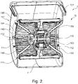
- FIG 2 a further embodiment of a radial fan 1 is shown.
- the embodiment of the centrifugal fan shown in figure 2 shown differs from the embodiment shown in FIG figure 1 in particular in that the radial air outlet 107 of the fan housing in the second embodiment has no exhaust port. Rather, the radial air outlet opening in the second embodiment has a rectangular cross section.
- one of the motor mounts 104 is formed by a cup-shaped member.
- the motor mount 103 is formed by an annular member as in the first embodiment.
- a damping element 112 is accommodated in each of the motor mounts 103, 104, via which one end of the motor shaft 110 is held in the motor mount 103, 104 in each case. The motor shaft 110 is thus held in the motor mounts 103, 104 in a rotationally fixed manner.
- the fan housing 10 is formed by two housing shells 100, 101, which are connected at a parting plane T, which is perpendicular to the axis of the motor shaft 110.
- connection arms can be two, three, four, five or more.
- shape of the motor mount may differ from the shape shown.
- the motor mount only has to be designed in such a way that a fixed part of the motor, for example an end of the motor shaft or a shaft, can be accommodated directly or indirectly in it and preferably held in a twist-proof manner.
- the present invention creates a design of a fan preferably consisting of an electric motor with a standing shaft (external rotor), fan wheel attached to the outer cylindrical surface of the rotor of the electric motor, and two fan housing shells, which allows easy assembly of the fan.
- the present invention has a number of advantages.
- assembly can be carried out without any additional parts take place.
- the two housing shells can, for example, be locked together or joined together with additional connecting elements.
- the connecting arms and the motor mounts provided thereon the motor of the radial fan is also automatically fixed.
- the present invention is advantageous due to the reduced number of necessary components of the fan and the simple assembly of the fan without additional components such as screws and brackets.
- the fan housing according to the invention can consist of only two housing shells.
- the assembly of the engine can thus be done easily, quickly and inexpensively.
Landscapes
- Engineering & Computer Science (AREA)
- Mechanical Engineering (AREA)
- General Engineering & Computer Science (AREA)
- Structures Of Non-Positive Displacement Pumps (AREA)
Abstract
Description
- Die vorliegende Erfindung betrifft ein Gebläsegehäuse und ein Radialgebläse, insbesondere für eine Dunstabzugsvorrichtung.
- In der
EP 2 236 838 A1 ist Radialgebläse beschrieben. Das Radialgebläse weist mindestens eine axiale Lufteintrittsöffnung und eine radiale Luftausblasöffnung auf. Das Radialgebläse besteht aus einer Gehäusebaugruppe und einer Lüfterbaugruppe, die einen Elektromotor und ein Lüfterrad umfasst, wobei die Gehäusebaugruppe mindestens ein Halteteil, das im Bereich der axialen Lufteintrittsöffnung angeordnet ist und zur lagernden Aufnahme eines Trägerteils der Lüfterbaugruppe dient, und zwei lösbar miteinander verbindbare die Lufteintrittsöffnung teilende Schalenteile aufweist, zwischen denen das Halteteil im Montagezustand befestigt ist, sowie einen Klemmenkasten zur Aufnahme von Motoranschlüssen. Bei diesem Radialgebläse ist auf jeder Seite des Gebläsegehäuses ein Halteteil jeweils zwischen der oberen und der unteren Schalenteilen gehalten. - Ein Nachteil dieser Ausgestaltung des Radialgebläses besteht darin, dass dessen Montage aufwändig ist.
- Aufgabe der vorliegenden Erfindung ist es daher ein Lösung zu schaffen, mittels derer ein Radialgebläses möglichst einfach montiert werden kann.
- Gemäß einem ersten Aspekt wird die Aufgabe daher gelöst durch ein Gebläsegehäuse für ein Radialgebläse, wobei das Gebläsegehäuse zwei Lufteintrittsöffnungen und zwei Gehäuseschalen aufweist. Das Gebläsegehäuse ist dadurch gekennzeichnet, dass in jeder der Gehäuseschalen eine der Lufteintrittsöffnungen gebildet ist und an jeder Lufteintrittsöffnung eine Motorhalterung angeordnet ist.
- Als Gebläsegehäuse wird das Gehäuse bezeichnet, in dem der Motor des Radialgebläses aufgenommen ist. Der Motor des Radialgebläses ist vorzugsweise ein Außenläufermotor, der aus einer feststehenden Welle und einem darauf gelagerten Rotor besteht. An dem äußeren Umfang des Rotors ist das Lüfterrad gebildet. Das Gebläsegehäuse stellt vorzugsweise ein Spiralgehäuse dar. Das Gebläsegehäuse wird durch zwei Gehäuseschalen gebildet. Die Gehäuseschalen sind vorzugsweise als Gehäusehälften ausgestaltet. Die Gehäuseschalen werden mit deren offenen Seiten zueinander gewandt miteinander verbunden. In jeder der Gehäuseschalen ist eine der zwei Lufteintrittsöffnungen des Gehäuses gebildet. Insbesondere liegt in jeder Gehäuseschale eine Lufteintrittsöffnung. Die Lufteintrittsöffnung liegt in dem Boden der Gehäuseschale. Im montierten Zustand des Gebläsegehäuses liegen die Lufteintrittsöffnungen einander gegenüber. Das Gebläsegehäuse weist zudem eine radiale Luftauslassöffnung auf. Diese wird durch Aussparungen an den Gehäuseschalen nach dem Zusammenfügen der Gehäuseschalen gebildet.
- An jeder der Lufteintrittsöffnungen ist eine Motorhalterung angeordnet. Als Motorhalterung wird eine Vorrichtung bezeichnet, die zumindest das Ende der Motorwelle des Motors oder eines Schaftes, auf dem die Motorwelle gehalten ist, halten kann. Insbesondere weist die Motorhalterung daher vorzugsweise eine Ringform oder Napfform auf. Die Motorhalterung ist vorzugsweise mittig an der Lufteintrittsöffnung angeordnet.
- Indem bei dem erfindungsgemäßen Gebläsegehäuse in jeder der Gehäuseschalen eine Lufteintrittsöffnung gebildet ist und an der Lufteintrittsöffnung eine Motorhalterung angeordnet ist, vereinfacht sich die Montage des Gebläsegehäuses. Insbesondere ist ein Positionieren und Ausrichtung eines Befestigungselementes in der Lufteintrittsöffnung während der Montage nicht erforderlich. Bei dem erfindungsgemäßen Gebläsegehäuse ist stattdessen die Motorhalterung bereits vor der Montage des Gebläsegehäuses an der Lufteintrittsöffnung vorgesehen. Somit ist bei der Montage des Radialgebläses lediglich das Platzieren des Motors zwischen den Gehäuseschalen und ein Verbinden der Gehäuseschalen miteinander erforderlich.
- Gemäß einer Ausführungsform wird die Motorhalterung an der Lufteintrittsöffnung durch mindestens einen Verbindungsarm gehalten. Als Verbindungsarm wird ein Stab oder eine Strebe verstanden, der beziehungsweise die die Motorhalterung in der Lufteintrittsöffnung in Position hält. Insbesondere weist der Verbindungsarm einen geringen Querschnitt auf. Indem ein oder vorzugsweise mehrere Verbindungsarme zu Befestigung der Motorhalterung verwendet wird, ist die Versperrung der Lufteintrittsöffnung gering. Damit kann ein zuverlässiges Einsaugen von Luft über die Lufteintrittsöffnung gewährleistet werden.
- Gemäß einer Ausführungsform ist ein Ende des Verbindungsarms mit dem Umfang der Lufteintrittsöffnung der Gehäuseschale verbunden und das andere Ende des Verbindungsarms ist mit der Motorhalterung verbunden. Vorzugsweise erstreckt sich der Verbindungsarm von dem Umfang der Lufteintrittsöffnung in radialer Richtung nach innen. Zudem ist der Verbindungsarm vorzugsweise in Richtung der offenen Seite der Gehäuseschale, an der dieser Verbindungsarm vorgesehen ist, geneigt. Somit liegt die Motorhalterung in einer Ebene, die zu dem Boden der Gehäuseschale, in dem die Lufteintrittsöffnung gebildet ist, in Richtung auf die offene Seite der Gehäuseschale versetzt ist. Hierdurch ist der Abstand zwischen den Motorhalterungen der beiden Gehäuseschalen im zusammengebauten Zustand des Gebläsegehäuses geringer als der Abstand zwischen den Böden der Gehäuseschalen, in denen die Lufteintrittsöffnungen liegen. Somit können die Motorhalterungen unmittelbar die Enden der Welle des Motors des Radialgebläses halten beziehungsweise die Länge eines Schaftes, auf dem die Welle gehalten ist, kann eine geringe Länge aufweisen.
- Die Verbindung zwischen dem Verbindungsarm und der Gehäuseschale ist vorzugsweise unlösbar. Zudem ist vorzugsweise auch die Verbindung der Motorhalterung mit dem Verbindungsarm unlösbar. Hierdurch ist bei der Montage des Gebläsegehäuses eine Ausrichtung des Verbindungsarms weder zu dem Umfang der Lufteintrittsöffnung noch zu der Motorhalterung erforderlich.
- Gemäß einer bevorzugten Ausführungsform ist der Verbindungsarm mit der Gehäuseschale und der Motorhalterung einteilig ausgebildet. Beispielsweise können die Gehäuseschale, der Verbindungsarm und die Motorhalterung durch Spritzguss als ein Bauteil hergestellt werden. Indem der Verbindungsarm mit der Gehäuseschale und der Motorhalterung einteilig ist, ist zudem die Stabilität des Gehäuses, insbesondere hinsichtlich der Halterung des Motors in dem Gebläsegehäuse gewährleistet.
- Gemäß einer Ausführungsform weist zumindest eine der Gehäuseschalen ein Verbindungselement zum Verbinden mit der weiteren Gehäuseschale auf. Insbesondere kann das Verbindungselement ein Rastelement darstellen. Bei dem erfindungsgemäßen Gebläsegehäuse müssen lediglich die Gehäuseschalen miteinander verbunden werden und dadurch ist auch der Motor durch die Motorhalterungen in dem Gebläsegehäuse gehalten. Die Anforderungen an das Verbindungselement zum Verbinden der zwei Gehäuseschalen sind daher reduziert. Indem das Verbindungselement an zumindest einer Gehäuseschale vorgesehen ist, ist die Anzahl an Teilen, die zur Montage des Gebläsegehäuse notwendig sind, reduziert.
- Gemäß einer Ausführungsform ist das Verbindungselement ein Rastelement. Bei dieser Ausführungsform kann an einer Gehäuseschale ein Rastelement und an der anderen Gehäuseschale eine entsprechende Rastaussparung zum Zusammenwirken mit dem Rastelement vorgesehen sein. Durch diese Ausgestaltung ist die Montage des Gebläsegehäuses weiter vereinfacht, da zur Montage keine Werkzeuge notwendig sind.
- Gemäß einem weiteren Aspekt betrifft die vorliegende Erfindung ein Radialgebläse, das dadurch gekennzeichnet ist, dass das Radialgebläse ein erfindungsgemäßes Gebläsegehäuse und einen Motor mit einem um eine feststehende Motorwelle laufenden Lüfterrad aufweist.
- Vorteile und Merkmale, die bezüglich des Gebläsegehäuses beschrieben wurden, gelten - soweit anwendbar - auch für das Radialgebläse und umgekehrt.
- Der Motor des Radialgebläses stellt vorzugsweise einen Elektromotor, insbesondere einen Außenläufermotor dar. Die Motorwelle erstreckt sich in dem Radialgebläse vorzugsweise zwischen den Lufteintrittsöffnungen des Gehäuses und die Enden der Motorwelle werden in den Motorhalterungen, die an den Lufteintrittsöffnungen angeordnet sind, gehalten.
- Gemäß einer Ausführungsform verläuft die Trennebene des Gebläsegehäuses zwischen den Gehäuseschalen senkrecht zu der Achse der Motorwelle. Auf diese Weise können die Gehäuseschalen miteinander verbunden werden und dabei den Motor mit Lüfterrad zwischen diesen aufnehmen.
- Gemäß einer Ausführungsform verläuft die Trennebene durch die Mitte der Länge der Motorwelle. Hierdurch kann die Abmessung der beiden Gehäuseschalen in Richtung der Motorwelle gleich sein.
- Gemäß einer Ausführungsform weist die Motorhalterung einen Aufnahmeraum für die Welle des Motors, insbesondere ein Ende der Motorwelle, auf. Insbesondere weist die Motorhalterung einen Durchmesser auf, der zumindest dem Durchmesser der Welle des Motors des Radialgebläse entspricht. Gemäß einer Ausführungsform kann die Motorhalterung einen Aufnahmeraum für die Welle des Motors, insbesondere ein Ende der Motorwelle, und ein die Welle umgebendes Dämpfungselement aufweisen. In dieser Ausführungsform ist der Durchmesser des Aufnahmeraumes größer als der der Motorwelle.
- Gemäß einer weiteren Ausführungsform ist der Aufnahmeraum für die Aufnahme eines Endes eines Schaftes, auf dem die Motorwelle gehalten wird, ausgelegt. In dieser Ausführungsform kann der Durchmesser des Aufnahmeraumes dem Durchmesser des Schaftes entsprechen. Gemäß einer weiteren Ausführungsform kann der Aufnahmeraum zur Aufnahme des Endes des Schaftes und ein dieses umgebenden Dämpfungselementes ausgelegt sein. In dieser Ausführungsform ist der Durchmesser des Aufnahmeraumes größer als der Durchmesser des Schaftes.
- Die Erfindung wird im Folgenden erneut unter Bezugnahme auf die beiliegenden Figuren genauer beschrieben. Es zeigen:
-
Figur 1 : eine schematische, perspektivische Teilschnittansicht einer Ausführungsform eines erfindungsgemäßen Gebläses; und -
Figur 2 : eine schematische, perspektivische Teilschnittansicht einer weiteren Ausführungsform eines erfindungsgemäßen Gebläses. - Gleiche Bestandteile des Radialgebläses werden in Figuren mit den gleichen Bezugszeichen bezeichnet und werden gegebenenfalls nur einmalig beschrieben.
- In
Figur 1 ist eine Ausführungsform eines erfindungsgemäßen Radialgebläses 1 gezeigt. Ein Segment des Radialgebläses 1 ist weggeschnitten, um den Einblick in das Innere des Radialgebläses 1 zu erlauben. Das Radialgebläse 1 besteht aus einem Gebläsegehäuse 10 und einem darin gelagerten Motor 11. Der Motor 11 stellt einen Elektromotor mit einer stehenden Motorwelle 110 und einem an der äußeren Zylinderfläche des auf der Motorwelle 110 laufenden Rotors angebrachten Lüfterrad 111 dar. Die Motorwelle 110 ist in dem Gebläsegehäuse 10 gehalten. Das Gebläsegehäuse 10 besteht in der gezeigten Ausführungsform aus zwei Gehäuseschalen 100 und 101. In jeder der Gehäuseschalen 100, 101 ist eine Lufteintrittsöffnung 102 mittig vorgesehen. Über die Lufteintrittsöffnungen 102 kann bei Betrieb des Radialgebläses 1 Luft eingesaugt werden. Die Luft wird dann über den radialen Luftauslass 107 ausgegeben, der in der Mantelfläche des Gebläsegehäuses 10 liegt. In der inFigur 1 gezeigten Ausführungsform ist in dem Luftauslass 107 ein ringförmiger Auslassstutzen 108 vorgesehen. Der Luftauslass 107 wird durch Aussparungen an den Gehäuseschalen 100, 101 gebildet. Der Auslassstutzen 108 kann in den Luftauslass 107 eingebracht werden. Alternativ ist jeweils eine Hälfte des Auslassstutzens 108 an der Gehäuseschale 100 und der Gehäuseschale 101 angeformt und der Auslassstutzen 108 wird durch das Zusammenfügen der Gehäuseschalen 100, 101 gebildet. - Die Trennebene T, die das Gebläsegehäuse 10 in die Gehäuseschalen 100, 101 teilt, steht senkrecht zu der Achse der Motorwelle 110. An jeder der Gehäuseschalen 100, 101 sind Verbindungsarme 105 vorgesehen. Die Verbindungsarme 105 dienen der Halterung der Motorwelle 110. Insbesondere sind die Verbindungsarme 105 so angeordnet, dass diese sich von dem Umfang der Lufteintrittsöffnung 102 radial nach innen erstrecken. Zudem sind die Verbindungsarme 105 so ausgebildet, dass diese ins Innere des Gebläsegehäuses 10 gerichtet sind. Das Ende des Verbindungsarmes 10, das dem Ende, an dem dieser an der Lufteintrittsöffnung 102 befestigt ist, gegenüberliegt, ist eine Motorhalterung 103, 104 vorgesehen. Bei der in
Figur 1 gezeigten rechten Gehäuseschale 100 ist die Motorhalterung mit 103 und bei der inFigur 2 gezeigten linken Gehäuseschale 101 ist die Motorhalterung mit 104 bezeichnet. Die Motorhalterungen 103, 104 sind in der gezeigten Ausführungsform als Ring ausgestaltet. Die Motorhalterungen 103, 104 greifen jeweils an den gegenüberliegenden Enden der Motorwelle 110 an. Insbesondere können die Enden der Motorwelle 110 gegebenenfalls über Dämpfungselement in der Öffnung der ringförmigen Motorhalterung 103, 104 aufgenommen werden. - Die Gehäuseschalen 100, 101 sind über Verbindungselemente 106 aneinander befestigt.
- Zur Montage des Radialgebläses 1 muss somit lediglich der Motor 11 zwischen den Gehäuseschalen 100, 101 positioniert werden und die Gehäuseschalen 100, 101 miteinander verbunden werden. Durch die an den Verbindungsarmen 105 vorgesehenen Motorhalterungen 103, 104 wird dabei der Motor 11 in dem Gebläsegehäuse 10 gehalten.
- In
Figur 2 ist eine weitere Ausführungsform eines Radialgebläses 1 gezeigt. Die Ausführungsform des Radialgebläses, die inFigur 2 gezeigt ist, unterscheidet sich von der Ausführungsform nachFigur 1 insbesondere dadurch, dass der radiale Luftauslass 107 des Gebläsegehäuses in der zweiten Ausführungsform keinen Abluftstutzen aufweist. Vielmehr weist die radiale Luftauslassöffnung in der zweiten Ausführungsform einen rechteckigen Querschnitt auf. Zudem ist in der gezeigten Ausführungsform eine der Motorhalterungen 104 durch eine napfförmiges Element gebildet. Die Motorhalterung 103 ist hingegen, wie in der ersten Ausführungsform durch ein ringförmiges Element gebildet. In den Motorhalterungen 103, 104 ist jeweils ein Dämpfungselement 112 aufgenommen, über das jeweils ein Ende der Motorwelle 110 in der Motorhalterung 103, 104 gehalten ist. Damit ist die Motorwelle 110 verdrehfest in den Motorhalterungen 103, 104 gehalten. - Auch bei der zweiten Ausführungsform ist das Gebläsegehäuse 10 durch zwei Gehäuseschalen 100, 101 gebildet, die an einer Trennebene T, die senkrecht zu der Achse der Motorwelle 110 liegt, verbunden sind.
- Die vorliegende Erfindung ist nicht auf die gezeigten Ausführungsformen beschränkt. Beispielsweise kann die Anzahl der Verbindungsarme zwei, drei, vier, fünf oder mehr betragen. Zudem kann beispielsweise die Form der Motorhalterung von der gezeigten Form abweichen. Die Motorhalterung muss lediglich so ausgestaltet sein, dass in dieser mittelbar oder unmittelbar ein feststehender Teil des Motors, beispielsweise ein Ende der Motorwelle oder eines Schaftes aufgenommen und vorzugsweise verdrehsicher gehalten werden kann.
- Die vorliegende Erfindung schafft eine Gestaltung eines Gebläses vorzugsweise bestehend aus einem Elektromotor mit stehender Welle (Außenläufter), Lüfterrad an der äußeren Zylinderfläche des Rotors des Elektromotors angebracht, sowie zwei Lüftergehäuseschalen, die eine einfache Montage des Gebläses erlaubt.
- Die vorliegende Erfindung weist eine Reihe von Vorteilen auf. Insbesondere kann durch die senkrecht zur Motorwelle und vorzugsweise mittig verlaufende Gehäuseteilung und die Integration von beidseitigen Motorhalterungen, die auch als Motoraufnahmehalterung bezeichnet werden können, mit Verbindungsarmen zu den beiden Gehäuseschalen an der Lufteintrittsöffnung, die auch als Lufteintritt bezeichnet werden kann, die Montage ohne weitere Zusatzteile erfolgen. Die beiden Gehäuseschalen können beispielsweise miteinander verrastet oder mit zusätzlichen Verbindungselementen zusammengefügt werden. Hierdurch wird aufgrund der Verbindungsarme und den daran vorgesehenen Motorhalterungen automatisch auch der Motor des Radialgebläses fixiert.
- Zudem ist die vorliegende Erfindung vorteilhaft aufgrund der geringeren Anzahl der notwendigen Bauteile des Gebläses und des einfachen Zusammenbaus des Gebläses ohne weitere Zusatzkomponenten, wie Schrauben und Klammern. Im Gegensatz zu dem bekannten Gebläsegehäuse, bei dem dieses aus einem unteren und einem oberen Schaltenteil mit zwei zwischen diesen gehaltenen zwei Halteteilen besteht, kann das erfindungsgemäße Gebläsegehäuse aus lediglich zwei Gehäuseschalen bestehen.
- Die Montage des Motors kann somit einfach, schnell und kostengünstig erfolgen.
-
- 1
- Radialgebläse
- 10
- Gebläsegehäuse
- 100
- Gehäuseschale
- 101
- Gehäuseschale
- 102
- Lufteintrittsöffnung
- 103
- Motorhalterung
- 104
- Motorhalterung
- 105
- Verbindungsarm
- 106
- Verbindungselement
- 107
- Luftauslass
- 108
- Auslassstutzen
- 11
- Motor
- 110
- Motorwelle
- 111
- Lüfterrad
- 112
- Dämpfungselement
- T
- Trennebene
Claims (9)
- Gebläsegehäuse für ein Radialgebläse (1), wobei das Gebläsegehäuse (10) zwei Lufteintrittsöffnungen (102) und zwei Gehäuseschalen (100, 101) aufweist, dadurch gekennzeichnet, dass in jeder der Gehäuseschalen (100, 101) eine der Lufteintrittsöffnungen (102) gebildet ist und an jeder Lufteintrittsöffnung (100, 101) eine Motorhalterung (103, 104) angeordnet ist.
- Gebläsegehäuse nach Anspruch 1, wobei die Motorhalterung (103, 104) an der Lufteintrittsöffnung (102) durch mindestens einen Verbindungsarm (105) gehalten wird, dessen eines Ende mit dem Umfang der Lufteintrittsöffnung (102) der Gehäuseschale (100, 101) verbunden ist und dessen anderes Ende mit der Motorhalterung (103, 104) verbunden ist.
- Gebläsegehäuse nach Anspruch 2, wobei der Verbindungsarm (105) mit der Gehäuseschale (100, 101) und der Motorhalterung (103, 104) einteilig ausgebildet ist.
- Gebläsegehäuse nach einem der Ansprüche 1 bis 3, wobei zumindest eine der Gehäuseschalen (100, 101) ein Verbindungselement (106) zum Verbinden mit der weiteren Gehäuseschale (101, 100) aufweist.
- Gebläsegehäuse nach Anspruch 4, wobei das Verbindungselement (106) ein Rastelement ist.
- Radialgebläse, dadurch gekennzeichnet, dass das Radialgebläse (10) ein Gebläsegehäuse (10) nach einem der Ansprüche 1 bis 5 und einen Motor (11) mit einem um eine feststehende Motorwelle (110) laufenden Lüfterrad (111) aufweist.
- Radialgebläse nach Anspruch 6, wobei eine Trennebene (T) des Gebläsegehäuses (10) zwischen den Gehäuseschalen (100, 101) senkrecht zu der Achse der Motorwelle (110) verläuft.
- Radialgebläse nach einem der Ansprüche 6 oder 7, wobei die Trennebene (T) durch die Mitte der Länge der Motorwelle (110) verläuft.
- Radialgebläse nach einem der Ansprüche 6 bis 8, wobei die Motorhalterung (103, 104) einen Aufnahmeraum für die Motorwelle (110) und ein die Motorwelle (110) umgebendes Dämpfungselement (112) aufweist.
Applications Claiming Priority (1)
| Application Number | Priority Date | Filing Date | Title |
|---|---|---|---|
| DE102021204150.7A DE102021204150A1 (de) | 2021-04-27 | 2021-04-27 | Gebläsegehäuse und Radialgebläse |
Publications (1)
| Publication Number | Publication Date |
|---|---|
| EP4083435A1 true EP4083435A1 (de) | 2022-11-02 |
Family
ID=80999154
Family Applications (1)
| Application Number | Title | Priority Date | Filing Date |
|---|---|---|---|
| EP22165738.0A Pending EP4083435A1 (de) | 2021-04-27 | 2022-03-31 | Gebläsegehäuse und radialgebläse |
Country Status (2)
| Country | Link |
|---|---|
| EP (1) | EP4083435A1 (de) |
| DE (1) | DE102021204150A1 (de) |
Citations (4)
| Publication number | Priority date | Publication date | Assignee | Title |
|---|---|---|---|---|
| US2776088A (en) * | 1956-02-09 | 1957-01-01 | Lau Blower Co | Blowers |
| US2936947A (en) * | 1956-11-27 | 1960-05-17 | Gen Electric | Motor mounting arrangement |
| EP2236838A1 (de) | 2009-03-25 | 2010-10-06 | ebm-papst Mulfingen GmbH & Co. KG | Radialgebläse |
| EP3415777A1 (de) * | 2017-06-13 | 2018-12-19 | ebm-papst Mulfingen GmbH & Co. KG | Gebläsegehäuseteil mit lageraufnahme sowie gebläse |
-
2021
- 2021-04-27 DE DE102021204150.7A patent/DE102021204150A1/de active Pending
-
2022
- 2022-03-31 EP EP22165738.0A patent/EP4083435A1/de active Pending
Patent Citations (4)
| Publication number | Priority date | Publication date | Assignee | Title |
|---|---|---|---|---|
| US2776088A (en) * | 1956-02-09 | 1957-01-01 | Lau Blower Co | Blowers |
| US2936947A (en) * | 1956-11-27 | 1960-05-17 | Gen Electric | Motor mounting arrangement |
| EP2236838A1 (de) | 2009-03-25 | 2010-10-06 | ebm-papst Mulfingen GmbH & Co. KG | Radialgebläse |
| EP3415777A1 (de) * | 2017-06-13 | 2018-12-19 | ebm-papst Mulfingen GmbH & Co. KG | Gebläsegehäuseteil mit lageraufnahme sowie gebläse |
Also Published As
| Publication number | Publication date |
|---|---|
| DE102021204150A1 (de) | 2022-10-27 |
Similar Documents
| Publication | Publication Date | Title |
|---|---|---|
| EP2338581B1 (de) | Lüftereinheit für Filterlüfter | |
| DE3809277B4 (de) | Lageranordnung für axial kompakten Kleinstventilator | |
| DE102013105524B4 (de) | Radiallüfter | |
| DE10204037C5 (de) | Radialgebläse mit Elektromotor | |
| WO1996010944A1 (de) | Arbeitsgerät zum rühren oder zerkleinern von nahrungsmitteln | |
| EP0985829B1 (de) | Gebläsegehäuse und Radialgebläse | |
| EP2481460A1 (de) | Filterelement eines Flüssigkeitsfilters und Flüssigkeitsfilter | |
| EP2778425A1 (de) | Doppelflutiges Radialgebläse für eine Dunstabzugshaube | |
| EP3441619B1 (de) | Kreiselpumpe | |
| EP3812546A1 (de) | Schraubenspindelpumpe | |
| DE2037993B2 (de) | Gehaeuse fuer kleinmotoren | |
| DE10001635B4 (de) | Zentrifugen-Separator | |
| DE69001630T2 (de) | Haltungssystem für verstellbare Leitschaufeln. | |
| EP3874170B1 (de) | Ventilatorgehäuse mit integrierter motorelektronik und ventilator mit einem entsprechenden ventilatorgehäuse | |
| DE3818651C2 (de) | ||
| DE69213116T2 (de) | Hermetisches Motorverdichtergehäuse | |
| EP2467606B1 (de) | Entkopplung eines antriebsmotors | |
| WO2018065155A1 (de) | Flüssigkeitspumpe | |
| DE4222264C2 (de) | Kühlvorrichtung für ein Kraftfahrzeug | |
| DE102021204150A1 (de) | Gebläsegehäuse und Radialgebläse | |
| EP0800000B1 (de) | Gebläse einer Heizung - und/oder Klimaanlage | |
| EP2778428A2 (de) | Verbindungsanordnung für ein Radialgebläse einer Dunstabzugshaube | |
| DE29921543U1 (de) | Filtereinsatz für einen Flüssigkeitsfilter | |
| EP0975069A2 (de) | Berührungssicheres Sockel-/ Fassungssystem für Leuchten | |
| EP1083073A2 (de) | Endseitige Haltevorrichtung für eine Entlüftungsleitung eines Aktivkohlefilters |
Legal Events
| Date | Code | Title | Description |
|---|---|---|---|
| PUAI | Public reference made under article 153(3) epc to a published international application that has entered the european phase |
Free format text: ORIGINAL CODE: 0009012 |
|
| STAA | Information on the status of an ep patent application or granted ep patent |
Free format text: STATUS: THE APPLICATION HAS BEEN PUBLISHED |
|
| AK | Designated contracting states |
Kind code of ref document: A1 Designated state(s): AL AT BE BG CH CY CZ DE DK EE ES FI FR GB GR HR HU IE IS IT LI LT LU LV MC MK MT NL NO PL PT RO RS SE SI SK SM TR |
|
| STAA | Information on the status of an ep patent application or granted ep patent |
Free format text: STATUS: REQUEST FOR EXAMINATION WAS MADE |
|
| 17P | Request for examination filed |
Effective date: 20230502 |
|
| RBV | Designated contracting states (corrected) |
Designated state(s): AL AT BE BG CH CY CZ DE DK EE ES FI FR GB GR HR HU IE IS IT LI LT LU LV MC MK MT NL NO PL PT RO RS SE SI SK SM TR |
|
| STAA | Information on the status of an ep patent application or granted ep patent |
Free format text: STATUS: EXAMINATION IS IN PROGRESS |
|
| 17Q | First examination report despatched |
Effective date: 20250110 |