EP4083399A1 - Brennkraftmaschine mit elektrischer abgasturbine und abgasnachbehandlungseinrichtung stromauf der abgasturbine - Google Patents
Brennkraftmaschine mit elektrischer abgasturbine und abgasnachbehandlungseinrichtung stromauf der abgasturbine Download PDFInfo
- Publication number
- EP4083399A1 EP4083399A1 EP22169031.6A EP22169031A EP4083399A1 EP 4083399 A1 EP4083399 A1 EP 4083399A1 EP 22169031 A EP22169031 A EP 22169031A EP 4083399 A1 EP4083399 A1 EP 4083399A1
- Authority
- EP
- European Patent Office
- Prior art keywords
- exhaust gas
- combustion engine
- internal combustion
- exhaust
- nitrogen oxide
- Prior art date
- Legal status (The legal status is an assumption and is not a legal conclusion. Google has not performed a legal analysis and makes no representation as to the accuracy of the status listed.)
- Granted
Links
Images

Classifications
-
- F—MECHANICAL ENGINEERING; LIGHTING; HEATING; WEAPONS; BLASTING
- F01—MACHINES OR ENGINES IN GENERAL; ENGINE PLANTS IN GENERAL; STEAM ENGINES
- F01N—GAS-FLOW SILENCERS OR EXHAUST APPARATUS FOR MACHINES OR ENGINES IN GENERAL; GAS-FLOW SILENCERS OR EXHAUST APPARATUS FOR INTERNAL-COMBUSTION ENGINES
- F01N13/00—Exhaust or silencing apparatus characterised by constructional features
- F01N13/009—Exhaust or silencing apparatus characterised by constructional features having two or more separate purifying devices arranged in series
-
- F—MECHANICAL ENGINEERING; LIGHTING; HEATING; WEAPONS; BLASTING
- F01—MACHINES OR ENGINES IN GENERAL; ENGINE PLANTS IN GENERAL; STEAM ENGINES
- F01N—GAS-FLOW SILENCERS OR EXHAUST APPARATUS FOR MACHINES OR ENGINES IN GENERAL; GAS-FLOW SILENCERS OR EXHAUST APPARATUS FOR INTERNAL-COMBUSTION ENGINES
- F01N3/00—Exhaust or silencing apparatus having means for purifying, rendering innocuous, or otherwise treating exhaust
- F01N3/02—Exhaust or silencing apparatus having means for purifying, rendering innocuous, or otherwise treating exhaust for cooling, or for removing solid constituents of, exhaust
- F01N3/021—Exhaust or silencing apparatus having means for purifying, rendering innocuous, or otherwise treating exhaust for cooling, or for removing solid constituents of, exhaust by means of filters
-
- F—MECHANICAL ENGINEERING; LIGHTING; HEATING; WEAPONS; BLASTING
- F01—MACHINES OR ENGINES IN GENERAL; ENGINE PLANTS IN GENERAL; STEAM ENGINES
- F01N—GAS-FLOW SILENCERS OR EXHAUST APPARATUS FOR MACHINES OR ENGINES IN GENERAL; GAS-FLOW SILENCERS OR EXHAUST APPARATUS FOR INTERNAL-COMBUSTION ENGINES
- F01N3/00—Exhaust or silencing apparatus having means for purifying, rendering innocuous, or otherwise treating exhaust
- F01N3/08—Exhaust or silencing apparatus having means for purifying, rendering innocuous, or otherwise treating exhaust for rendering innocuous
- F01N3/10—Exhaust or silencing apparatus having means for purifying, rendering innocuous, or otherwise treating exhaust for rendering innocuous by thermal or catalytic conversion of noxious components of exhaust
- F01N3/18—Exhaust or silencing apparatus having means for purifying, rendering innocuous, or otherwise treating exhaust for rendering innocuous by thermal or catalytic conversion of noxious components of exhaust characterised by methods of operation; Control
- F01N3/20—Exhaust or silencing apparatus having means for purifying, rendering innocuous, or otherwise treating exhaust for rendering innocuous by thermal or catalytic conversion of noxious components of exhaust characterised by methods of operation; Control specially adapted for catalytic conversion
- F01N3/2006—Periodically heating or cooling catalytic reactors, e.g. at cold starting or overheating
- F01N3/2033—Periodically heating or cooling catalytic reactors, e.g. at cold starting or overheating using a fuel burner or introducing fuel into exhaust duct
-
- F—MECHANICAL ENGINEERING; LIGHTING; HEATING; WEAPONS; BLASTING
- F01—MACHINES OR ENGINES IN GENERAL; ENGINE PLANTS IN GENERAL; STEAM ENGINES
- F01N—GAS-FLOW SILENCERS OR EXHAUST APPARATUS FOR MACHINES OR ENGINES IN GENERAL; GAS-FLOW SILENCERS OR EXHAUST APPARATUS FOR INTERNAL-COMBUSTION ENGINES
- F01N3/00—Exhaust or silencing apparatus having means for purifying, rendering innocuous, or otherwise treating exhaust
- F01N3/08—Exhaust or silencing apparatus having means for purifying, rendering innocuous, or otherwise treating exhaust for rendering innocuous
- F01N3/10—Exhaust or silencing apparatus having means for purifying, rendering innocuous, or otherwise treating exhaust for rendering innocuous by thermal or catalytic conversion of noxious components of exhaust
- F01N3/18—Exhaust or silencing apparatus having means for purifying, rendering innocuous, or otherwise treating exhaust for rendering innocuous by thermal or catalytic conversion of noxious components of exhaust characterised by methods of operation; Control
- F01N3/20—Exhaust or silencing apparatus having means for purifying, rendering innocuous, or otherwise treating exhaust for rendering innocuous by thermal or catalytic conversion of noxious components of exhaust characterised by methods of operation; Control specially adapted for catalytic conversion
- F01N3/206—Adding periodically or continuously substances to exhaust gases for promoting purification, e.g. catalytic material in liquid form, NOx reducing agents
- F01N3/2066—Selective catalytic reduction [SCR]
-
- F—MECHANICAL ENGINEERING; LIGHTING; HEATING; WEAPONS; BLASTING
- F01—MACHINES OR ENGINES IN GENERAL; ENGINE PLANTS IN GENERAL; STEAM ENGINES
- F01N—GAS-FLOW SILENCERS OR EXHAUST APPARATUS FOR MACHINES OR ENGINES IN GENERAL; GAS-FLOW SILENCERS OR EXHAUST APPARATUS FOR INTERNAL-COMBUSTION ENGINES
- F01N5/00—Exhaust or silencing apparatus combined or associated with devices profiting by exhaust energy
- F01N5/04—Exhaust or silencing apparatus combined or associated with devices profiting by exhaust energy the devices using kinetic energy
-
- F—MECHANICAL ENGINEERING; LIGHTING; HEATING; WEAPONS; BLASTING
- F01—MACHINES OR ENGINES IN GENERAL; ENGINE PLANTS IN GENERAL; STEAM ENGINES
- F01N—GAS-FLOW SILENCERS OR EXHAUST APPARATUS FOR MACHINES OR ENGINES IN GENERAL; GAS-FLOW SILENCERS OR EXHAUST APPARATUS FOR INTERNAL-COMBUSTION ENGINES
- F01N2240/00—Combination or association of two or more different exhaust treating devices, or of at least one such device with an auxiliary device, not covered by indexing codes F01N2230/00 or F01N2250/00, one of the devices being
- F01N2240/14—Combination or association of two or more different exhaust treating devices, or of at least one such device with an auxiliary device, not covered by indexing codes F01N2230/00 or F01N2250/00, one of the devices being a fuel burner
-
- F—MECHANICAL ENGINEERING; LIGHTING; HEATING; WEAPONS; BLASTING
- F01—MACHINES OR ENGINES IN GENERAL; ENGINE PLANTS IN GENERAL; STEAM ENGINES
- F01N—GAS-FLOW SILENCERS OR EXHAUST APPARATUS FOR MACHINES OR ENGINES IN GENERAL; GAS-FLOW SILENCERS OR EXHAUST APPARATUS FOR INTERNAL-COMBUSTION ENGINES
- F01N2340/00—Dimensional characteristics of the exhaust system, e.g. length, diameter or volume of the exhaust apparatus; Spatial arrangements of exhaust apparatuses
- F01N2340/06—Arrangement of the exhaust apparatus relative to the turbine of a turbocharger
-
- F—MECHANICAL ENGINEERING; LIGHTING; HEATING; WEAPONS; BLASTING
- F01—MACHINES OR ENGINES IN GENERAL; ENGINE PLANTS IN GENERAL; STEAM ENGINES
- F01N—GAS-FLOW SILENCERS OR EXHAUST APPARATUS FOR MACHINES OR ENGINES IN GENERAL; GAS-FLOW SILENCERS OR EXHAUST APPARATUS FOR INTERNAL-COMBUSTION ENGINES
- F01N2610/00—Adding substances to exhaust gases
- F01N2610/02—Adding substances to exhaust gases the substance being ammonia or urea
-
- Y—GENERAL TAGGING OF NEW TECHNOLOGICAL DEVELOPMENTS; GENERAL TAGGING OF CROSS-SECTIONAL TECHNOLOGIES SPANNING OVER SEVERAL SECTIONS OF THE IPC; TECHNICAL SUBJECTS COVERED BY FORMER USPC CROSS-REFERENCE ART COLLECTIONS [XRACs] AND DIGESTS
- Y02—TECHNOLOGIES OR APPLICATIONS FOR MITIGATION OR ADAPTATION AGAINST CLIMATE CHANGE
- Y02T—CLIMATE CHANGE MITIGATION TECHNOLOGIES RELATED TO TRANSPORTATION
- Y02T10/00—Road transport of goods or passengers
- Y02T10/10—Internal combustion engine [ICE] based vehicles
- Y02T10/12—Improving ICE efficiencies
Definitions
- the invention relates to an internal combustion engine with an internal combustion engine and an exhaust system in which an electric exhaust gas turbine, i.e. an exhaust gas turbine that is drive-connected to an electric machine, and an exhaust gas aftertreatment device are integrated.
- an electric exhaust gas turbine i.e. an exhaust gas turbine that is drive-connected to an electric machine, and an exhaust gas aftertreatment device are integrated.
- Such an internal combustion engine is both from the DE 10 2016 200 923 A1 as well as from the DE 10 2017 220 524 B3 known. It is also disclosed therein that the generator load of the exhaust gas turbine can be varied in a targeted manner in order to control a temperature of the exhaust gas routed via the exhaust line.
- the internal combustion engines disclosed in these documents each also include an exhaust gas aftertreatment device that is integrated into the exhaust line and is arranged downstream of the respective electric exhaust gas turbine.
- the DE 10 2018 130 799 A1 describes an internal combustion engine for a motor vehicle.
- the internal combustion engine is supercharged by means of an exhaust gas turbocharger, which has a fresh gas compressor and an exhaust gas turbine, which are connected to one another by a drive shaft.
- an exhaust gas turbocharger which has a fresh gas compressor and an exhaust gas turbine, which are connected to one another by a drive shaft.
- a burner is provided in an exhaust system of the internal combustion engine upstream of the exhaust gas turbine, in which a fuel can be exothermically converted.
- the drive shaft of the exhaust gas turbocharger is at least indirectly connected to a crankshaft of an internal combustion engine of the internal combustion engine in order to recover at least part of the exhaust gas enthalpy released by the burner.
- the object of the invention was to improve the exhaust gas emission behavior of an internal combustion engine.
- an internal combustion engine which comprises an internal combustion engine and an exhaust line for discharging exhaust gas from the internal combustion engine (and for at least partially discharging it into the environment), with at least one (electric) exhaust gas turbine, which is drive-connected to an electric machine, and a (first) exhaust gas aftertreatment device are integrated. It is provided that the (first) exhaust gas aftertreatment device is integrated into the exhaust system upstream of the exhaust gas turbine.
- Such an internal combustion engine advantageously enables a method according to the invention to be carried out, in which, at least temporarily, the electric machine is operated as a generator or as a motor depending on the temperature of the exhaust gas upstream of the exhaust gas turbine, in particular the temperature at at least one point in the (first) exhaust gas aftertreatment device, or is controlled depending on the thermal state of the (first) exhaust gas aftertreatment device.
- the electric machine drive-connected to the exhaust gas turbine is temporarily operated as a generator for targeted temperature control (i.e. heating up or maintaining the temperature) of the first exhaust gas aftertreatment device to an extent that is relatively high and in particular exceeds the current requirements of the Fresh gas compressor goes beyond.
- a relatively large drive resistance for the exhaust gas turbine or for the associated turbine impeller is thus generated in a targeted manner by means of the electric machine, as a result of which the exhaust gas is dammed up to a relatively large extent upstream of the exhaust gas turbine.
- increased heat transfer to the (first) exhaust gas aftertreatment device integrated into the exhaust line upstream of the exhaust gas turbine can be implemented, which can have an advantageous effect on the temperature control of this exhaust gas aftertreatment device.
- such a method according to the invention can be carried out in particular during a warm-up phase of the internal combustion engine, which can follow a cold start in particular, and/or during regeneration operation of the internal combustion engine, in which the first exhaust gas aftertreatment device or at least one exhaust gas aftertreatment component thereof is thermally regenerated.
- a "cold start” is basically a start-up of the internal combustion engine in which at least one exhaust gas aftertreatment component of the exhaust gas aftertreatment device(s) has an operating temperature that corresponds approximately (i.e. with a deviation of up to 10K, 20K or 30K) to the ambient temperature.
- a warm-up phase must take place do not always follow a cold start or a start-up of the internal combustion engine with an operating temperature below an associated light-off temperature of at least one exhaust gas aftertreatment component; Rather, a warm-up phase can also begin with the internal combustion engine and in particular the internal combustion engine being operated beforehand in such a way that the previously exceeded light-off temperature is again undershot, as may be the case when the internal combustion engine is idling or overrun for a longer period of time.
- the (first) exhaust gas aftertreatment device has at least one oxidation catalytic converter (preferably with a loading of precious metal (e.g. platinum), which more preferably less than 100 g/ft 3 or 3.53 kg/m 3 is) and/or a nitrogen oxide store (particularly in an embodiment as a nitrogen oxide storage catalytic converter or as a nitrogen oxide adsorber) and/or a particle filter.
- oxidation catalytic converter preferably with a loading of precious metal (e.g. platinum), which more preferably less than 100 g/ft 3 or 3.53 kg/m 3 is
- a nitrogen oxide store particularly in an embodiment as a nitrogen oxide storage catalytic converter or as a nitrogen oxide adsorber
- the nitrogen oxide reservoir can advantageously also be applied as a coating to a filter body of the particle filter.
- the oxidation catalytic converter can in particular provide for the oxidation of unburned hydrocarbons (HC) and carbon monoxide (CO), while the nitrogen oxide reservoir can temporarily bind nitrogen oxides (NOx) contained in the exhaust gas.
- the particle filter removes particles, in particular soot particles, from the exhaust gas.
- a fresh gas compressor is integrated in a fresh gas line of the internal combustion engine, which is provided for supplying fresh gas to the internal combustion engine.
- the fresh gas consists at least partially of air that has been sucked in from the environment. Provision can then also preferably be made for the fresh-gas compressor to be drive-connected to the electric machine or to a further electric machine. If the fresh-gas compressor is drive-connected to another electric machine, a complete mechanical decoupling of the exhaust-gas turbine and the fresh-gas compressor can be implemented, although these are electrically coupled, so that the drive machine coupled to the exhaust-gas turbine can provide electrical power that is required for the required drive of the fresh gas compressor driving additional electric machine is needed.
- the electrical energy generated can preferably, if necessary, in one of the Electric machines connected storage device, such as a battery, are temporarily stored, whereby in particular a drive of the fresh gas compressor by means of the electric machine drive-connected thereto can be temporally decoupled from a generator or electric power of the electric machine coupled to the exhaust gas turbine.
- Connecting such a storage device to the electric machine that is drive-connected to the exhaust-gas turbine can also be advantageous if no fresh-gas compressor is provided or if the fresh-gas compressor is mechanically coupled to the exhaust-gas turbine, because this electrical energy is generated within the scope of a method according to the invention by generator operation of the drive-connected electric machine was provided with the exhaust gas turbine, can be cached.
- An internal combustion engine according to the invention in which the fresh-gas compressor is also drive-connected to an electric machine, makes it possible to carry out a method according to the invention, in which at least temporarily a generator or motor operation of this electric machine is controlled depending on the temperature of the exhaust gas upstream of the exhaust gas turbine.
- a generator or motor operation of this electric machine is controlled depending on the temperature of the exhaust gas upstream of the exhaust gas turbine.
- a resulting reduction in the filling of the combustion chamber or chambers of the internal combustion engine can advantageously support internal engine measures that are implemented specifically to achieve relatively hot exhaust gases.
- a drive-related decoupling of the fresh-gas compressor from the exhaust-gas turbine by connecting it to its own electric machine also makes it possible to flexibly position the fresh-gas compressor and the exhaust-gas turbine, which can be particularly advantageous when integrating an internal combustion engine according to the invention into a motor vehicle.
- this makes it possible to advantageously position the fresh gas compressor on a side of the internal combustion engine on which the fresh gas line opens into the internal combustion engine, as a result of which this side of the internal combustion engine is relatively cold.
- the fresh-gas compressor can be designed in a relatively simple and therefore cost-effective manner.
- An internal combustion engine can also preferably have at least one exhaust gas recirculation line (with associated exhaust gas recirculation valve) which branches off from the exhaust line and opens into the fresh gas line.
- the exhaust gas recirculation line can preferably be upstream of the exhaust gas turbine and more preferably downstream of the first Branch off the exhaust gas aftertreatment device from the exhaust system, because this allows, within the scope of a method according to the invention, at least temporarily a generator or motor operation of the electric machine or at least one of the electric machines depending on the pressure drop present across the exhaust gas recirculation line (overpressure on the side of the exhaust gas line compared to the Fresh gas line) is controlled.
- the electric machine drive-connected to the exhaust-gas turbine is temporarily (also) operated as a generator for the targeted increase in the pressure drop to an extent that exceeds the current requirement of the fresh-gas compressor.
- the exhaust-gas recirculation line can preferably open into the fresh-gas line upstream of the fresh-gas compressor.
- Such an exhaust gas recirculation line is also referred to below as a low-pressure exhaust gas recirculation line, although, unlike conventional low-pressure exhaust gas recirculation lines, it branches off from the exhaust system upstream of the exhaust gas turbine.
- an internal combustion engine according to the invention can also include a further exhaust gas recirculation line, in particular a high-pressure exhaust gas recirculation line, which also branches off from the forced exhaust gas duct upstream of the exhaust gas turbine (and in particular also upstream of the (first) exhaust gas aftertreatment device) and which opens into the fresh gas line downstream of the exhaust gas turbine.
- a further exhaust gas recirculation line in particular a high-pressure exhaust gas recirculation line, which also branches off from the forced exhaust gas duct upstream of the exhaust gas turbine (and in particular also upstream of the (first) exhaust gas aftertreatment device) and which opens into the fresh gas line downstream of the exhaust gas turbine.
- a further exhaust gas recirculation line in particular a high-pressure exhaust gas recirculation line, which also branches off from the forced exhaust gas duct upstream of the exhaust gas turbine (and in particular also upstream of the (first) exhaust gas aftertreatment device) and which opens into the fresh gas line downstream of the exhaust gas turbine.
- An internal combustion engine according to the invention can also preferably have a second exhaust gas aftertreatment device, which is integrated into the exhaust system downstream of the exhaust gas turbine, in order to reduce pollutants in the exhaust gas as completely as possible in all operating states of the internal combustion engine.
- a second exhaust gas aftertreatment device which is integrated into the exhaust system downstream of the exhaust gas turbine, in order to reduce pollutants in the exhaust gas as completely as possible in all operating states of the internal combustion engine.
- the implementation of a method according to the invention can preferably also be provided, in which at least temporarily generator or motor operation of the electric machine or at least one of the electric machines is carried out depending on the temperature of the exhaust gas downstream of the exhaust gas turbine or depending on the thermal state of the second exhaust aftertreatment device is controlled.
- the second exhaust gas aftertreatment device preferably comprises at least one nitrogen oxide reduction catalytic converter (in particular an SCR catalytic converter) and a heating device assigned to it, i.e. by operating the heating device, at least the nitrogen oxide reduction catalytic converter can be heated in a targeted manner.
- the heating device can be integrated into the nitrogen oxide reduction catalytic converter or, preferably, upstream of it in the exhaust system, in order to bring about indirect heating of the nitrogen oxide reduction catalytic converter via the exhaust gas.
- a nitrogen oxide reduction catalytic converter of the second exhaust gas aftertreatment device can be particularly useful if, as is preferably provided, the first exhaust gas aftertreatment device arranged upstream of the exhaust gas turbine only comprises a nitrogen oxide storage device (and no nitrogen oxide reduction catalytic converter).
- the nitrogen oxide reduction catalytic converter can then ensure a reduction in the nitrogen oxides and thus their conversion into harmless components when nitrogen oxides in the exhaust gas are no longer stored by the nitrogen oxide storage device, for example because its storage capacity is exhausted, or are even released by it, as is the case with a Nitrogen oxide storage can usually be the case when it is heated to a temperature above a defined operating temperature (desorption temperature). Such a release of nitrogen oxides from the nitrogen oxide reservoir can also be intentional, in particular if the nitrogen oxides can be reduced to a sufficient extent by means of the nitrogen oxide reduction catalytic converter (because it has an operating temperature that is above its light-off temperature (e.g. approx.
- 230° C is from which sufficient effectiveness in terms of nitrogen oxide reduction can be assumed) to increase the storage capacity of the nitrogen oxide store again. As a result, it can be available for storing nitrogen oxides in a later operating state of the internal combustion engine when the nitrogen oxides cannot be reduced to a sufficient extent by means of the nitrogen oxide reduction catalytic converter.
- an internal combustion engine due to the arrangement of the first exhaust gas after-treatment device with the nitrogen oxide storage device preferably included therein, upstream of the exhaust gas turbine and thus relatively close to the internal combustion engine, as well as due to the possible accumulation of exhaust gas due to generator operation of the electric machine drive-connected to the exhaust gas turbine, very rapid heating of the first exhaust gas aftertreatment device and thus the nitrogen oxide storage device, it should preferably be ensured that the nitrogen oxide reduction catalytic converter, which is preferably part of the second exhaust gas aftertreatment device integrated into the exhaust line downstream of the exhaust gas turbine, and therefore only relatively slowly Thermal energy, which the exhaust gas already has when leaving the internal combustion engine, is heated, has already reached its light-off temperature when the nitrogen oxide storage device, which is heating up quickly, reaches its desorption temperature. This can be ensured by operating the heating device that is preferably provided. It can thereby be ensured that nitrogen oxides, which have been released from the nitrogen oxide store after the desorption temperature has been reached, are reduced to a sufficient extent by the nitrogen oxide reduction catalytic converter
- the heating device can be operated at the same time, the targeted temperature control being achieved by operating the electric machine drive-connected to the exhaust-gas turbine as a generator it is controlled that the nitrogen oxide reduction catalytic converter of the second exhaust gas aftertreatment device reaches its light-off temperature before the nitrogen oxide storage device of the first exhaust gas aftertreatment device reaches its desorption temperature.
- the heating device should have a sufficiently high heat output to ensure that the nitrogen oxide reduction catalytic converter preferably included in the second exhaust gas aftertreatment device reaches its light-off temperature correspondingly quickly .
- the heating device has a maximum (peak) heating output of at least 15 kW, 20 kW, 25 kW or 30 kW.
- Such heat outputs can be achieved in particular by means of a burner, so that an internal combustion engine according to the invention with a heating device preferably includes such a burner.
- This burner can also preferably be arranged upstream of the nitrogen oxide reduction catalytic converter in the exhaust system in order to bring about indirect heating of the nitrogen oxide reduction catalytic converter.
- a “burner” is understood to be a device that burns separately supplied fuel with oxygen, in particular as a component of air, and thereby generates a hot gas that can be used for direct heating or, by mixing with the exhaust gas, for indirect heating.
- the nitrogen oxide reduction catalytic converter is heated as uniformly as possible in the case of indirect heating by means of the heating device, it can preferably be provided that between the heating device and the nitrogen oxide reduction catalytic converter a mixing device is arranged in the exhaust system, as a result of which the exhaust gas can be mixed in such a way that it flows into the nitrogen oxide reduction catalytic converter at a temperature which is as homogeneous as possible over the flow cross section.
- the mixing device can also ensure that the reducing agent (eg ammonia or a liquid containing ammonia) to be introduced into the exhaust gas is distributed as uniformly as possible, which may be necessary for reducing the nitrogen oxides by means of the nitrogen oxide reduction catalytic converter.
- a corresponding injection device for the reducing agent should be arranged at least upstream of the mixing device that is preferably provided.
- Such an injection device is particularly preferably also arranged upstream of the heating device in order to provide a flow path between the injection device and the nitrogen oxide reduction catalytic converter which is sufficient for thorough mixing of the reducing agent with the exhaust gas.
- a nitrogen oxide reduction catalyst usually has an operating temperature range within which the nitrogen oxide reduction is sufficiently effective. This operating temperature range can extend from the light-off temperature (e.g. 230°C) as a lower limit to an upper limit of 550°C, for example. At an operating temperature of the nitrogen oxide reduction catalytic converter above this upper limit value, its ability to reduce nitrogen oxides can be limited and/or such a high operating temperature can have a negative effect on the service life or the ability to reduce nitrogen oxides over the service life of the nitrogen oxide reduction catalytic converter.
- the nitrogen oxide reduction catalytic converter In order to prevent the nitrogen oxide reduction catalytic converter from heating up above such an upper limit as far as possible, it is preferably a component of the second exhaust gas aftertreatment device arranged downstream of the exhaust gas turbine in the exhaust line, with which this is generally only subjected to relatively cold exhaust gas. Nevertheless, it could happen that, for example when the internal combustion engine is operated at full load for a relatively long time, exhaust gas which flows through the second exhaust gas aftertreatment device has a temperature which is above this upper limit value. In order to avoid this, it can be provided that a generator operation of the electric machine drive-connected to the exhaust gas turbine is temporarily controlled in order to specifically limit an operating temperature of the second exhaust gas aftertreatment device and in particular of the nitrogen oxide reduction catalytic converter.
- the temperature of the second exhaust gas treatment device in a targeted manner by relatively weak generator operation (up to and including non-operation) of the electric machine that is drive-connected to the exhaust gas turbine
- it can also be so low that it does not cover the current requirement of the fresh gas compressor.
- relatively little or even as little exhaust gas enthalpy as possible can be converted in the exhaust gas turbine, so that a relatively large amount of thermal energy in the exhaust gas is available for tempering the second exhaust gas aftertreatment devices.
- Such a procedure can be provided in particular during long-lasting low-load operation of the internal combustion engine.
- the second exhaust gas aftertreatment device can preferably (also) have an oxidation catalyst (preferably with a loading of noble metal (e.g. platinum), which is more preferably at least 50 g/ft 3 or 1.77 kg/m 3 ) and/or a Include nitrogen oxide storage and / or a particle filter (in one embodiment as an open or closed particle filter).
- the nitrogen oxide reservoir can furthermore preferably be arranged upstream of the nitrogen oxide reduction catalytic converter.
- the oxidation catalytic converter and/or the particle filter can preferably be arranged downstream of the nitrogen oxide reduction catalytic converter in the exhaust system.
- the oxidation catalytic converter can in particular also have the function of a blocking catalytic converter, by means of which a possible slip of reducing agent through the nitrogen oxide reduction catalytic converter is rendered harmless.
- the oxidation catalytic converter has a volume that corresponds to at least 50% or 80% or 100% of the displacement of the internal combustion engine.
- an electric drive machine can be provided which is drive-connected to the internal combustion engine.
- a motor vehicle that includes such an internal combustion engine according to the invention can therefore be designed in the form of a hybrid vehicle.
- the electric drive machine can advantageously be used to have effects on the drive power generated by the internal combustion engine, which result from the fact that the electric machine drive-connected to the exhaust gas turbine and/or the electric machine drive-connected to the fresh-gas compressor, depending on the temperature of exhaust gas is/are controlled upstream and/or downstream of the exhaust gas turbine and/or by the pressure drop present across the exhaust gas recirculation line, so that a total of the actual drive power generated by the internal combustion engine corresponds to an intended target drive power.
- a method according to the invention can in principle, at least temporarily, be used in conjunction with known internal engine measures that aim to generate relatively hot exhaust gas in order to heat up the exhaust system or system as quickly as possible to achieve the exhaust aftertreatment device(s) integrated therein.
- Such measures are, for example, a relatively late injection or post-injection of fuel.
- the internal combustion engine of an internal combustion engine according to the invention can preferably be self-igniting and in particular designed as a (self-igniting and quality-controlled) diesel engine.
- the internal combustion engine is a (spark-ignited and quantity-controlled) Otto engine or a combination thereof, i.e. e.g. an internal combustion engine with homogeneous compression ignition.
- the internal combustion engine can be operated with both liquid fuel (i.e. diesel or petrol) and gaseous fuel (especially natural gas, LNG or LPG).
- the invention further relates to a motor vehicle, in particular a wheel-based and non-rail-bound motor vehicle (preferably a car or a truck), with an internal combustion engine according to the invention.
- the internal combustion engine of the internal combustion engine can be provided in particular for the (direct or indirect) provision of the driving power for the motor vehicle.
- the first exhaust gas aftertreatment device can be arranged in particular in an engine compartment of the motor vehicle.
- the preferably provided second exhaust gas after-treatment devices can preferably be arranged below an underbody of the motor vehicle.
- the electric machine(s) of a motor vehicle according to the invention can be operated in particular with a nominal voltage of at least 48 V, preferably at least 100 V, in order to be able to generate sufficiently high drive power with relatively low electric currents.
- a configuration of an internal combustion engine according to the invention makes it possible to dispense with a throttle valve which is integrated in the fresh-gas line, in particular upstream of the fresh-gas compressor that is preferably provided.
- a conventional exhaust gas valve which is usually integrated into the exhaust system downstream of the branching of a low-pressure exhaust gas recirculation line, can also be dispensed with. The expense associated with the integration of such a throttle valve and/or exhaust gas valve can therefore be avoided.
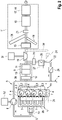
- the 1 an internal combustion engine according to the invention, as can be used as part of a motor vehicle.
- a plurality of combustion chambers 2 are formed in an internal combustion engine 1 of the internal combustion engine 1 .
- mixture quantities are burned in a known manner in a defined sequence in the combustion chambers 2, which are partially delimited by cylinder openings 3 of the internal combustion engine 1 and by pistons 4 guided movably therein, the pressure increases thus generated in the combustion chambers 2 being used to to move the pistons 4.
- These movements of the pistons 4 are converted into a rotational movement of a crankshaft (not shown) with the interposition of connecting rods (not shown), the guidance of the pistons 4 via the connecting rods by means of the crankshaft simultaneously resulting in a cyclic back-and-forth movement of the pistons 4 leads.
- the mixture quantities provided for combustion in the combustion chambers 2 include, on the one hand, fresh gas, which consists entirely or mainly of air that is sucked in from the environment, and which, after filtering in an air filter (not shown), goes to the internal combustion engine 1, controlled by means of intake valves (not shown) of the internal combustion engine 1, via a fresh gas line 5 is supplied.
- the fresh gas is guided via a fresh gas compressor 6 integrated into the fresh gas line 5, by means of which the fresh gas can be compressed.
- the fresh gas can then be routed through a charge air cooler 33 in order to at least partially reverse an increase in the temperature of the fresh gas that has occurred as a result of the compression.
- the quantities of the mixture also include fuel, which can be introduced directly into the combustion chambers 2 and burned by means of fuel injectors 7 .
- the (raw) exhaust gas produced during the combustion of the fresh gas/fuel mixture in the combustion chambers 2 is discharged from the combustion chambers 2 , controlled by exhaust valves (not shown), and transferred to an exhaust system 8 .
- the exhaust gas then flows through firstly, a first exhaust gas aftertreatment device 9 integrated into the exhaust system 8, then an exhaust gas turbine 10 and then, at least in part, a second exhaust gas aftertreatment device 11. This exhaust gas is then discharged into the environment.
- the first exhaust gas aftertreatment device 9 comprises, viewed in the flow direction of the exhaust gas, an oxidation catalytic converter 12 and then a combination of a nitrogen oxide reservoir 13 and a particle filter 14, it being possible for the nitrogen oxide reservoir 13 to be designed as a coating on a filter body of the particle filter 14.
- the nitrogen oxide storage device 13 and the particle filter 14 are provided as separate exhaust gas aftertreatment components, the nitrogen oxide storage device 13 is arranged upstream of the particle filter 14 . Otherwise, the internal combustion engine corresponds to 2 that of 1 .
- the second exhaust gas aftertreatment device 11 comprises as exhaust gas aftertreatment components, seen in the direction of flow of the exhaust gas, an optional nitrogen oxide reservoir 15 in the form of a nitrogen oxide adsorber, a nitrogen oxide reduction catalytic converter 16 and a combination of an oxidation catalytic converter 17 and a particle filter 18, with the oxidation catalytic converter 17 also being coated on a filter body in this case of the particle filter 18 can be provided.
- the second exhaust gas aftertreatment device 11 also includes, in an arrangement between the nitrogen oxide storage device 15 and the nitrogen oxide reduction catalytic converter 16, an injection device 19 for a reducing agent, a heating device, preferably in the form of a burner 20, and a mixing device 21 (seen in this order in the direction of flow of the exhaust gas) .
- Part of the exhaust gas that is transferred to the exhaust line 17 can, if required, be routed via a first exhaust gas recirculation line 22 and/or an optional second exhaust gas recirculation line 23 and then introduced into the fresh gas line 13 in each case.
- a control valve 24 exhaust gas recirculation valve
- An exhaust gas filter 25 and an exhaust gas cooler 26 or a first heat exchange side thereof are also integrated into the first exhaust gas recirculation line 22 .
- the second heat exchange side of the exhaust gas cooler 26 is integrated into a cooling system 27 of the internal combustion engine, which in particular can also include the internal combustion engine 1 or cooling ducts thereof.
- the first exhaust gas recirculation line 22 branches off downstream of the first exhaust gas aftertreatment device 9 and upstream of the exhaust gas turbine 10 from the exhaust line 8 and opens upstream of the fresh gas compressor 6 in the fresh gas line 5.
- the only optionally provided second exhaust gas recirculation line 23 branches upstream of the first exhaust gas aftertreatment device 22 from the exhaust line 8, specifically from an exhaust manifold 28, i.e. from the first itself the section of the exhaust line 8 that follows the internal combustion engine 1 and in which the exhaust gas that originates from the individual combustion chambers 2 is combined.
- the second exhaust gas recirculation line 23 opens into the fresh gas line 5 downstream of the fresh gas compressor 6.
- the second exhaust gas recirculation line 23 opens into an intake manifold 29, which represents the last section of the fresh gas line 5, in which the fresh gas is divided between the individual combustion chambers 2 of the internal combustion engine 1.
- a connecting line 30 branches off from the first exhaust gas recirculation line 22 and specifically downstream of the exhaust gas cooler 26 and upstream of the control valve 24 and opens into the exhaust line 8 downstream of the exhaust gas turbine 10 and upstream of the second exhaust gas aftertreatment device 11 .
- a control valve 24 is also integrated into the connecting line 30 .
- the connecting line 30 makes it possible, if necessary, to route exhaust gas that is not intended for introduction into the fresh-gas line 5 (i.e. for exhaust gas recirculation) but for introduction into the environment via the exhaust gas cooler 26 . As a result, thermal energy of this exhaust gas can be transferred to the coolant of cooling system 27, so that particularly during a warm-up phase of the internal combustion engine, further components integrated into the cooling system, such as internal combustion engine 1, can be heated as quickly as possible.
- Both the exhaust gas turbine 10 and the fresh gas compressor 6 are each drive-connected to a (separate) electric machine 31, 32, these electric machines 31, 32 each being electrically connected to a storage device (not shown), for example a battery.
- a storage device for example a battery.
- the coupling of the exhaust gas turbine 10 and the fresh gas compressor 6 each with an electric machine 31, 32 enables advantageous operation of the internal combustion engine, in particular with regard to the exhaust gas emission behavior.
- the exhaust gas turbine 10 in a warm-up phase of the internal combustion engine, which can in particular follow immediately after a cold start, the exhaust gas turbine 10 is subjected to a relatively high generator load by means of the associated electric machine 31, as a result of which this or an associated turbine impeller rotates relatively slowly, which leads to a relatively strong accumulation of exhaust gas upstream of the exhaust gas turbine 10 leads.
- the first exhaust gas aftertreatment device 9 can be heated up relatively quickly, which can thereby ensure a substantially complete reduction in pollutants in the exhaust gas as quickly as possible.
- the burner 20 is put into operation in order to heat up at least the nitrogen oxide reduction catalytic converter 16 as quickly as possible.
- the nitrogen oxide reduction catalytic converter 16 should at least reach its light-off temperature sufficiently quickly. Nitrogen oxides, which the nitrogen oxide reservoir 13 of the first exhaust gas aftertreatment device has previously stored and which it has released again because its desorption temperature has been reached quickly, can then no longer pass through the nitrogen oxide reduction catalytic converter, so that it is prevented that they are discharged into the environment.
- Reducing agent for the reduction of nitrogen oxides by the nitrogen oxide reduction catalytic converter 16 can be introduced into the exhaust gas by means of the injection device 19 as soon as the mixing device 21 is sufficiently warm and as soon as at least a first section of the nitrogen oxide reduction catalytic converter 16 has reached the associated light-off temperature.
- the exhaust gases generated by the operation of the burner 20 can be post-treated to a sufficient extent by means of the combination of oxidation catalytic converter 17 and particle filter 18 of the second exhaust gas after-treatment device 11 .
- the fresh gas compressor 6 is not operated or is even loaded as a generator by means of the associated electric machine 32, as a result of which the fresh gas supplied to the internal combustion engine 1 can be severely throttled.
- This then leads to a reduction in the filling of the combustion chambers 2, which means that internal engine measures are implemented at the same time, which aim to generate relatively hot exhaust gas (which in turn is done with the aim of heating up the exhaust gas aftertreatment devices 9, 11 and in particular the first exhaust gas aftertreatment device 11 as quickly as possible). can support.
- Driving the fresh-gas compressor 6 by means of the associated electric machine also has the advantage that the fresh-gas compressor 6 or the compressor impeller thereof can be dimensioned relatively large because the disadvantage of a relatively large inertia associated with such a dimensioning is compensated for by the electric drive can be.
- Such a relatively large fresh gas compressor 6 has the advantage that only relatively low operating speeds are required to achieve a defined compression output. Relatively low operating speeds have the advantage, among other things, that the fresh-gas compressor 6 is relatively insensitive to water hammer.
- the relatively large dimensioning of the fresh gas compressor 6 therefore makes it possible to route exhaust gas via the first exhaust gas recirculation line 22 relatively quickly after a cold start of the internal combustion engine, although this exhaust gas, which is still relatively cold, is associated with an increased risk of water condensing and this water entering the fresh gas compressor 6 .
- the earliest possible exhaust gas recirculation has an advantageous effect, in particular with regard to the raw nitrogen oxide emissions of the internal combustion engine 1 .
- Exhaust gas recirculation can consequently be initiated shortly after the cold start of the internal combustion engine, which can then be accompanied at the same time as the already described generator operation of the electric machine 31 associated with the exhaust gas turbine 10 .
- the accumulation of exhaust gas upstream of the exhaust gas turbine 10 caused by this generator operation of the electric machine 31 then also has a positive effect with regard to the exhaust gas recirculation, because this results in a relatively large pressure drop across the first exhaust gas recirculation line 22, through which exhaust gas flows via the first exhaust gas recirculation line 22 can be effected.
- the relatively high pressure achieved in the branch of the first exhaust gas recirculation line 22 can also be particularly advantageous when, as already described, the pressure of the fresh gas in the region of the mouth of the first exhaust gas recirculation line 22 is relatively high as a result of non-operation or a generator load on the fresh gas compressor 6 is.
- reduced generator operation or even motor operation of the electric machine 31 assigned to the exhaust gas turbine 10 in a low-load operation of the internal combustion engine 1 can be implemented in a targeted manner relatively or even as little as possible exhaust gas enthalpy in the exhaust gas turbine 10. This can be done with the aim of avoiding excessive cooling of the second exhaust gas aftertreatment device 11 and in particular of the nitrogen oxide reduction catalytic converter 16 thereof.
Landscapes
- Engineering & Computer Science (AREA)
- Chemical & Material Sciences (AREA)
- Combustion & Propulsion (AREA)
- Mechanical Engineering (AREA)
- General Engineering & Computer Science (AREA)
- Chemical Kinetics & Catalysis (AREA)
- Health & Medical Sciences (AREA)
- Toxicology (AREA)
- Supercharger (AREA)
- Exhaust Gas After Treatment (AREA)
Abstract
Description
- Die Erfindung betrifft eine Brennkraftmaschine mit einem Verbrennungsmotor und einem Abgasstrang, in den eine elektrische Abgasturbine, d.h. eine Abgasturbine, die mit einer Elektromaschine antriebsverbunden ist, und eine Abgasnachbehandlungseinrichtung integriert sind.
- Eine derartige Brennkraftmaschine ist sowohl aus der
DE 10 2016 200 923 A1 als auch aus derDE 10 2017 220 524 B3 bekannt. Darin ist auch offenbart, dass die generatorische Last der Abgasturbine gezielt zur Steuerung einer Temperatur des über den Abgasstrang geführten Abgases variiert werden kann. Die in diesen Druckschriften offenbarten Brennkraftmaschinen umfassen jeweils auch eine in den Abgasstrang integrierte Abgasnachbehandlungseinrichtung, die stromab der jeweiligen elektrischen Abgasturbine angeordnet ist. - Die
DE 10 2018 130 799 A1 beschreibt einen Brennkraftmaschine für ein Kraftfahrzeug. Die Brennkraftmaschine ist mittels eines Abgasturboladers aufgeladen, der einen Frischgasverdichter und eine Abgasturbine aufweist, die durch eine Antriebswelle miteinander verbunden sind. Um Abgasnachbehandlungskomponenten der Brennkraftmaschine nach einem Kaltstart möglichst schnell auf eine Betriebstemperatur aufzuheizen, ist in einem Abgasstrang der Brennkraftmaschine stromaufwärts der Abgasturbine ein Brenner vorgesehen, in dem ein Brennstoff exotherm umgesetzt werden kann. Die Antriebswelle des Abgasturboladers ist zumindest mittelbar mit einer Kurbelwelle eines Verbrennungsmotors der Brennkraftmaschine verbunden, um zumindest einen Teil der von dem Brenner freigesetzten Abgasenthalpie zurückzugewinnen. - Der Erfindung lag die Aufgabe zugrunde, das Abgasemissionsverhalten einer Brennkraftmaschine zu verbessern .
- Diese Aufgabe ist bei einer Brennkraftmaschine gemäß dem Patentanspruch 1 gelöst. Ein Verfahren zum Betreiben einer solchen Brennkraftmaschine ist Gegenstand des Patentanspruchs 12. Vorteilhafte Ausgestaltungsformen der erfindungsgemäßen Brennkraftmaschine und bevorzugte Ausführungsformen des erfindungsgemäßen Verfahrens sind Gegenstände der weiteren Patentansprüche und/oder ergeben sich aus der nachfolgenden Beschreibung der Erfindung.
- Erfindungsgemäß ist eine Brennkraftmaschine vorgesehen, die einen Verbrennungsmotor und einen Abgasstrang zum Abführen von Abgas von dem Verbrennungsmotor (und zum zumindest teilweisen Einleiten in die Umgebung) umfasst, wobei in den Abgasstrang zumindest eine (elektrische) Abgasturbine, die mit einer Elektromaschine antriebsverbunden ist, und eine (erste) Abgasnachbehandlungseinrichtung integriert sind. Dabei ist vorgesehen, dass die (erste) Abgasnachbehandlungseinrichtung stromauf der Abgasturbine in den Abgasstrang integriert ist.
- Eine solche Brennkraftmaschine ermöglicht in vorteilhafter Weise die Durchführung eines erfindungsgemäßen Verfahrens, bei dem zumindest temporär ein generatorischer oder motorischer Betrieb der Elektromaschine in Abhängigkeit von der Temperatur von Abgas stromauf der Abgasturbine, insbesondere der Temperatur an zumindest einer Stelle in der (ersten) Abgasnachbehandlungseinrichtung, beziehungsweise in Abhängigkeit von dem thermischen Zustand der (ersten) Abgasnachbehandlungseinrichtung gesteuert wird. Insbesondere kann dazu vorgesehen sein, dass die mit der Abgasturbine antriebsverbundene Elektromaschine temporär zur gezielten Temperierung (d.h. einem Aufheizen oder Auf-Temperatur-Halten) der ersten Abgasnachbehandlungseinrichtung in einem Maße generatorisch betrieben wird, der relativ hoch ist und der insbesondere über den aktuellen Bedarf des Frischgasverdichters hinausgeht. Mittels der Elektromaschine wird somit gezielt ein relativ großer Antriebswiderstand für die Abgasturbine beziehungsweise für das dazugehörige Turbinenlaufrad erzeugt, wodurch das Abgas stromauf der Abgasturbine in einem relativ großen Ausmaß aufgestaut wird. Dadurch kann ein erhöhter Wärmeübergang auf die stromauf der Abgasturbine in den Abgasstrang integrierte (erste) Abgasnachbehandlungseinrichtung realisiert werden, was sich vorteilhaft auf die Temperierung dieser Abgasnachbehandlungseinrichtung auswirken kann. Vor diesem Hintergrund kann ein solches erfindungsgemäßes Verfahren insbesondere während einer Warmlaufphase der Brennkraftmaschine, die sich insbesondere an einen Kaltstart anschließen kann, und/oder während eines Regenerationsbetriebs der Brennkraftmaschine, in der die erste Abgasnachbehandlungseinrichtungen beziehungsweise zumindest eine Abgasnachbehandlungskomponenten davon thermisch regeneriert wird, durchgeführt werden.
- Als "Warmlaufphase" gilt grundsätzlich ein Betrieb der Brennkraftmaschine, bei der zumindest eine Abgasnachbehandlungskomponente der Abgasnachbehandlungseinrichtung(en) eine Betriebstemperatur aufweisen, die unter der dazugehörigen Anspringtemperatur liegt. Als "Kaltstart" gilt grundsätzlich eine Inbetriebnahme der Brennkraftmaschine, bei der zumindest eine Abgasnachbehandlungskomponente der Abgasnachbehandlungseinrichtung(en) eine Betriebstemperatur aufweisen, die ungefähr (d.h. auch mit einer Abweichung von bis zu 10K, 20K oder 30K) der Umgebungstemperatur entspricht. Eine Warmlaufphase muss sich dabei nicht immer an einen Kaltstart oder an eine Inbetriebnahme der Brennkraftmaschine mit einer unterhalb einer dazugehörigen Anspringtemperatur liegenden Betriebstemperatur zumindest einer Abgasnachbehandlungskomponente anschließen; vielmehr kann eine Warmlaufphase auch damit beginnen, dass die Brennkraftmaschine und insbesondere der Verbrennungsmotor zuvor derart betrieben wurde, dass die zuvor bereits überschrittene Anspringtemperatur wieder unterschritten wird, wie dies gegebenenfalls bei einem länger andauernden Leerlauf- oder Schubbetrieb des Verbrennungsmotors der Fall sein kann.
- Gemäß einer bevorzugten Ausgestaltungsform einer erfindungsgemäßen Brennkraftmaschine kann vorgesehen sein, dass die (erste) Abgasnachbehandlungseinrichtung zumindest einen Oxidationskatalysator (vorzugsweise mit einer Beladung mit Edelmetall (z.B. Platin), die weiterhin bevorzugt weniger als 100 g/ft3 beziehungsweise 3,53 kg/m3 beträgt) und/oder einen Stickoxidspeicher (insbesondere in einer Ausgestaltung als Stickoxidspeicherkatalysator oder als Stickoxidadsorber) und/oder einen Partikelfilter umfasst. Der Stickoxidspeicher kann dabei vorteilhaft auch als Beschichtung auf einem Filterkörper des Partikelfilters aufgebracht sein. Besonders bevorzugt ist vorgesehen, dass die (erste) Abgasnachbehandlungseinrichtung einen Oxidationskatalysator und einen Stickoxidspeicher und einen Partikelfilter umfasst, weil dadurch eine weitgehend vollständige Nachbehandlung des Abgases hinsichtlich der zu eliminierenden Schadstoffe möglich ist. Der Oxidationskatalysator kann dabei insbesondere für eine Oxidation von unverbrannten Kohlenwasserstoffen (HC) und Kohlenmonoxid (CO) sorgen, während der Stickoxidspeicher temporär in dem Abgas enthaltene Stickoxide (NOx) binden kann. Der Partikelfilter entfernt dagegen Partikel, insbesondere Rußpartikel, aus dem Abgas.
- Gemäß einer weiterhin bevorzugten Ausgestaltungsform einer erfindungsgemäßen Brennkraftmaschine kann vorgesehen sein, dass in einen Frischgasstrang der Brennkraftmaschine, der für ein Zuführen von Frischgas zu dem Verbrennungsmotor vorgesehen ist, ein Frischgasverdichter integriert ist. Das Frischgas besteht dabei zumindest teilweise aus Luft, die aus der Umgebung angesaugt wurde. Weiterhin bevorzugt kann dann noch vorgesehen sein, dass der Frischgasverdichter mit der Elektromaschine oder einer weiteren Elektromaschine antriebsverbunden ist. Sofern der Frischgasverdichter mit einer weiteren Elektromaschine antriebsverbunden ist, kann besonders bevorzugt eine vollständige mechanische Entkopplung der Abgasturbine und des Frischgasverdichters realisiert sein, wobei diese jedoch elektrisch gekoppelt sind, so dass mittels der mit der Abgasturbine gekoppelten Antriebsmaschine elektrische Leistung bereitgestellt werden kann, die für den bedarfsweisen Antrieb der den Frischgasverdichter antreibenden weiteren Elektromaschine benötigt wird. Dabei kann die erzeugte elektrische Energie vorzugsweise bedarfsweise in einer an die Elektromaschinen angeschlossenen Speichervorrichtung, beispielsweise einer Batterie, zwischengespeichert werden, wodurch insbesondere ein Antrieb des Frischgasverdichters mittels der damit antriebsverbunden Elektromaschine zeitlich von einer generatorischen beziehungsweise elektrischen Leistung der mit der Abgasturbine gekoppelten Elektromaschine entkoppelt werden kann. Ein Anschluss einer solchen Speichervorrichtung an die mit der Abgasturbine antriebsverbundene Elektromaschine kann auch dann vorteilhaft sein, wenn kein Frischgasverdichter vorgesehen ist oder wenn der Frischgasverdichter mit der Abgasturbine mechanisch gekoppelt ist, weil dadurch elektrische Energie, die im Rahmen eines erfindungsgemäßen Verfahrens durch einen generatorischen Betrieb der mit der Abgasturbine antriebsverbundene Elektromaschine bereitgestellt wurde, zwischengespeichert werden kann.
- Eine erfindungsgemäße Brennkraftmaschine, bei der auch der Frischgasverdichter mit einer Elektromaschine antriebsverbunden ist, ermöglicht die Durchführung eines erfindungsgemäßen Verfahrens, bei dem zumindest temporär ein generatorischer oder motorischer Betrieb dieser Elektromaschine in Abhängigkeit von der Temperatur von Abgas stromauf der Abgasturbine gesteuert wird. Beispielsweise kann vorgesehen sein, dass für ein gezieltes Temperieren der (ersten) Abgasnachbehandlungseinrichtung durch einen generatorischen oder einen gezielt relativ schwachen motorischen Betrieb der mit dem Frischgasverdichter antriebsverbundenen Elektromaschine ein Drosseln von über den Frischgasstrang dem Verbrennungsmotor zuzuführendem Frischgas erreicht wird. Eine daraus folgende Reduktion der Füllung des oder der Brennräume des Verbrennungsmotors kann innermotorische Maßnahmen, die gezielt zur Erzielung relativ heißen Abgases umgesetzt werden, vorteilhaft unterstützen.
- Eine antriebstechnische Entkopplung des Frischgasverdichters von der Abgasturbine durch dessen Antriebsverbindung mit einer eigenen Elektromaschine ermöglicht weiterhin, den Frischgasverdichter wie auch die Abgasturbine flexibel positionieren zu können, was sich insbesondere vorteilhaft bei der Integration einer erfindungsgemäßen Brennkraftmaschine in ein Kraftfahrzeug auswirken kann. Zudem wird dadurch ermöglicht, den Frischgasverdichter vorteilhaft auf einer Seite des Verbrennungsmotors zu positionieren, auf der der Frischgasstrang in den Verbrennungsmotor mündet, wodurch diese Seite des Verbrennungsmotors relativ kalt ist. Dadurch kann der Frischgasverdichter konstruktiv relativ einfach und damit kostengünstig ausgestaltet sein.
- Eine erfindungsgemäße Brennkraftmaschine kann weiterhin bevorzugt zumindest eine Abgasrückführleitung (mit zugeordnetem Abgasrückführventil) aufweisen, die aus dem Abgasstrang abzweigt und in den Frischgasstrang mündet. Die Abgasrückführleitung kann dabei vorzugsweise stromauf der Abgasturbine und weiterhin bevorzugt stromab der ersten Abgasnachbehandlungseinrichtung aus dem Abgasstrang abzweigen, weil dies ermöglicht, dass im Rahmen eines erfindungsgemäßen Verfahrens zumindest temporär ein generatorischer oder motorischer Betrieb der Elektromaschine oder zumindest einer der Elektromaschinen in Abhängigkeit von dem über der Abgasrückführleitung anliegenden Druckgefälle (Überdruck auf der Seite des Abgasstrangs im Vergleich zu dem Frischgasstrang) gesteuert wird. Insbesondere kann vorgesehen sein, dass die mit der Abgasturbine antriebsverbundene Elektromaschine temporär (auch) zur gezielten Erhöhung des Druckgefälles in einem Maße generatorisch betrieben wird, der über den aktuellen Bedarf des Frischgasverdichters hinausgeht.
- Die Abgasrückführleitung kann bei einer erfindungsgemäßen Brennkraftmaschine, die einen in den Frischgasstrang integrierten Frischgasverdichter aufweist, vorzugsweise stromauf des Frischgasverdichters in den Frischgasstrang münden. Eine solche Abgasrückführleitung wird nachfolgend auch als Niederdruck-Abgasrückführleitung bezeichnet, obwohl diese, anders als konventionelle Niederdruck-Abgasrückführleitungen, stromauf der Abgasturbine aus dem Abgasstrang abzweigt.
- Eine erfindungsgemäße Brennkraftmaschine kann grundsätzlich auch noch eine weitere Abgasrückführleitung, insbesondere eine Hochdruck-Abgasrückführleitung umfassen, die ebenfalls stromauf der Abgasturbine (und insbesondere auch stromauf der (ersten) Abgasnachbehandlungseinrichtung) aus dem Abgaszwang abzweigt und die stromab der Abgasturbine in den Frischgasstrang mündet. Vorzugsweise ist jedoch vorgesehen, dass eine erfindungsgemäße Brennkraftmaschine eine solche Hochdruck-Abgasrückführleitung nicht umfasst, weil diese aufgrund der erfindungsgemäßen Ausgestaltung einer Brennkraftmaschine funktional vermeidbar ist. Der mit der Integration einer solchen Hochdruck-Abgasrückführleitung verbundene Aufwand kann daher vermieden werden.
- Eine erfindungsgemäße Brennkraftmaschine kann weiterhin bevorzugt eine zweite Abgasnachbehandlungseinrichtung, die stromab der Abgasturbine in den Abgasstrang integriert ist, aufweisen, um eine möglichst vollständige Reduktion von Schadstoffen in dem Abgas in sämtlichen Betriebszuständen der Brennkraftmaschine zu realisieren. Bei einer solchen erfindungsgemäßen Brennkraftmaschine kann vorzugsweise auch die Durchführung eines erfindungsgemäßen Verfahrens vorgesehen sein, bei dem zumindest temporär ein generatorischer oder motorischer Betrieb der Elektromaschine oder zumindest einer der Elektromaschinen in Abhängigkeit von der Temperatur von Abgas stromab der Abgasturbine beziehungsweise in Abhängigkeit von dem thermischen Zustand der zweiten Abgasnachbehandlungseinrichtung gesteuert wird.
- Vorzugsweise umfasst die zweite Abgasnachbehandlungseinrichtung zumindest einen Stickoxidreduktionskatalysator (insbesondere SCR-Katalysator) und eine diesem zugeordnete Heizvorrichtung, d.h. durch einen Betrieb der Heizvorrichtung kann gezielt zumindest eine Erwärmung des Stickoxidreduktionskatalysators bewirkt werden. Hierzu kann die Heizvorrichtung in den Stickoxidreduktionskatalysator integriert oder, vorzugsweise, stromauf davon in dem Abgasstrang angeordnet sein, um über das Abgas eine indirekte Beheizung des Stickoxidreduktionskatalysators zu bewirken. Ein solcher Stickoxidreduktionskatalysator der zweiten Abgasnachbehandlungseinrichtung kann insbesondere dann sinnvoll sein, wenn, wie dies vorzugsweise vorgesehen ist, die erste, stromauf der Abgasturbine angeordnete Abgasnachbehandlungseinrichtung lediglich einen Stickoxidspeicher (und keinen Stickoxidreduktionskatalysator) umfasst. Der Stickoxidreduktionskatalysator kann dann für eine Reduktion der Stickoxide und damit für deren Umwandlung in unschädliche Bestandteile sorgen, wenn Stickoxide in dem Abgas von dem Stickoxidspeicher nicht mehr eingelagert werden, beispielsweise weil dessen Speicherkapazität ausgeschöpft ist, oder von diesem sogar freigesetzt werden, wie dies bei einem Stickoxidspeicher üblicherweise der Fall sein kann, wenn dieser bis zu einer Temperatur, die über einer definierten Betriebstemperatur (Desorptionstemperatur) liegt, erwärmt wird. Ein solches Freisetzen von Stickoxiden aus dem Stickoxidspeicher kann dabei auch gewollt sein, um insbesondere dann, wenn in einem ausreichenden Maße eine Reduktion der Stickoxide mittels des Stickoxidreduktionskatalysators bewirkt werden kann (weil dieser eine Betriebstemperatur aufweist, die oberhalb seiner Anspringtemperatur (z.B. ca. 230°C) liegt, ab der von einer ausreichenden Wirksamkeit hinsichtlich der Stickoxidreduktion ausgegangen werden kann), die Speicherkapazität des Stickoxidspeichers wieder zu erhöhen. Dadurch kann dieser für eine Speicherung von Stickoxiden in einem späteren Betriebszustand der Brennkraftmaschine, wenn eine Reduktion der Stickoxide mittels des Stickoxidreduktionskatalysators nicht in einem ausreichenden Maße möglich ist, zur Verfügung stehen.
- Da eine erfindungsgemäße Brennkraftmaschine durch die Anordnung der ersten Abgasnachbehandlungseinrichtung mit dem vorzugsweise von dieser umfassten Stickoxidspeicher stromauf der Abgasturbine und damit relativ nah an dem Verbrennungsmotor sowie durch das erfindungsgemäß mögliche Aufstauen von Abgas durch einen generatorischen Betrieb der mit der Abgasturbine antriebsverbundenen Elektromaschine ein sehr schnelles Aufheizen der ersten Abgasnachbehandlungseinrichtung und damit des Stickoxidspeichers ermöglicht, sollte vorzugsweise gewährleistet sein, dass der Stickoxidreduktionskatalysator, der vorzugsweise Bestandteil der stromab der Abgasturbine in den Abgasstrang integrierten zweiten Abgasnachbehandlungseinrichtung ist und dadurch nur relativ langsam durch Wärmeenergie, die das Abgas bereits beim Verlassen des Verbrennungsmotors aufweist, erwärmt wird, seine Anspringtemperatur bereits erreicht hat, wenn der sich schnell aufheizende Stickoxidspeicher seine Desorptionstemperatur erreicht. Dies kann durch einen Betrieb der vorzugsweise vorgesehenen Heizvorrichtung gewährleistet werden. Dadurch kann sichergestellt werden, dass Stickoxide, die von dem Stickoxidspeicher nach dem Erreichen der Desorptionstemperatur freigesetzt wurden, von dem Stickoxidreduktionskatalysator in einem ausreichenden Maße reduziert werden.
- Dementsprechend kann gemäß einer bevorzugten Ausführungsform eines erfindungsgemäßen Verfahrens, bei dem die mit der Abgasturbine antriebsverbundene Elektromaschine temporär zur gezielten Temperierung der ersten Abgasnachbehandlungseinrichtung generatorisch betrieben wird, gleichzeitig die Heizvorrichtung betrieben werden, wobei die gezielte Temperierung durch den generatorischen Betrieb der mit der Abgasturbine antriebsverbundenen Elektromaschine so gesteuert wird, dass der Stickoxidreduktionskatalysator der zweiten Abgasnachbehandlungseinrichtung seine Anspringtemperatur erreicht bevor der Stickoxidspeicher der ersten Abgasnachbehandlungseinrichtung seine Desorptionstemperatur erreicht.
- Da die erste Abgasnachbehandlungseinrichtung erfindungsgemäß relativ schnell auch bis zum Erreichen der Desorptionstemperatur des vorzugsweise von dieser umfassten Stickoxidspeichers aufgeheizt werden kann, sollte die Heizvorrichtung eine ausreichend hohe Heizleistung aufweisen, um zu gewährleisten, dass der vorzugsweise von der zweiten Abgasnachbehandlungseinrichtung umfasste Stickoxidreduktionskatalysator entsprechend schnell seine Anspringtemperatur erreicht. Insbesondere kann vorgesehen sein, dass die Heizvorrichtung eine maximale (Peak-)Heizleistung von mindestens 15 kW, 20 kW, 25 kW oder 30 kW aufweist. Derartige Heizleistungen sind insbesondere mittels eines Brenners erzielbar, so dass eine erfindungsgemäße Brennkraftmaschine mit Heizvorrichtung vorzugsweise einen solchen Brenner umfasst. Dieser Brenner kann weiterhin bevorzugt stromauf des Stickoxidreduktionskatalysators in dem Abgasstrang angeordnet sein, um eine indirekte Beheizung des Stickoxidreduktionskatalysators zu bewirken. Als "Brenner" wird dabei eine Vorrichtung verstanden, die separat zugeführten Kraftstoff mit Sauerstoff, insbesondere als Bestandteil von Luft, verbrennt und dadurch ein Heißgas erzeugt, das zur direkten Beheizung oder, durch ein Vermischen mit dem Abgas, zur indirekte Beheizung genutzt werden kann.
- Um eine möglichst gleichmäßige Beheizung des Stickoxidreduktionskatalysators bei einer indirekten Beheizung mittels der Heizvorrichtung zu gewährleisten, kann vorzugsweise vorgesehen sein, dass zwischen der Heizvorrichtung und dem Stickoxidreduktionskatalysator eine Mischvorrichtung in dem Abgasstrang angeordnet ist, wodurch das Abgas so durchmischt werden kann, dass dieses mit einer möglichst homogenen Temperatur über dem Strömungsquerschnitt in den Stickoxidreduktionskatalysator einströmt. Ergänzend dazu kann die Mischvorrichtung auch für eine möglichst gleichmäßige Verteilung von in das Abgas einzubringendem Reduktionsmittel (z.B. Ammoniak oder eine ammoniakhaltige Flüssigkeit) sorgen, das für eine Reduktion der Stickoxide mittels des Stickoxidreduktionskatalysators erforderlich sein kann. Demnach sollte eine entsprechende Injektionsvorrichtung für das Reduktionsmittel zumindest stromauf der vorzugsweise vorgesehenen Mischvorrichtung angeordnet sein. Besonders bevorzugt ist eine solche Injektionsvorrichtung auch stromauf der Heizvorrichtung angeordnet, um einen für eine gute Durchmischung des Reduktionsmittels mit dem Abgas ausreichenden Strömungsweg zwischen der Injektionsvorrichtung und dem Stickoxidreduktionskatalysators bereitzustellen.
- Ein Stickoxidreduktionskatalysator weist üblicherweise einen Betriebstemperaturbereich auf, innerhalb dessen die Stickoxidreduktion ausreichend wirksam ist. Dieser Betriebstemperaturbereich kann sich von der Anspringtemperatur (z.B. 230°C) als unterem Grenzwert bis zu einem oberen Grenzwert von beispielsweise 550°C erstrecken. Bei einer Betriebstemperatur des Stickoxidreduktionskatalysators oberhalb dieses oberen Grenzwerts kann dessen Fähigkeit zur Stickoxidreduktion eingeschränkt sein und/oder eine derart hohe Betriebstemperatur kann sich negativ auf die Lebensdauer beziehungsweise die Stickoxidreduktionsfähigkeit über der Lebensdauer des Stickoxidreduktionskatalysators auswirken. Um ein Erwärmen des Stickoxidreduktionskatalysators über einen solchen oberen Grenzwert hinaus möglichst zu vermeiden, ist dieser vorzugsweise Bestandteil der zweiten, stromab der Abgasturbine in dem Abgasstrang angeordneten Abgasnachbehandlungseinrichtungen, womit dieser grundsätzlich mit nur noch relativ kaltem Abgas beaufschlagt wird. Dennoch könnte es vorkommen, dass, beispielsweise bei einem relativ lange andauernden Betrieb des Verbrennungsmotors mit Volllast, Abgas, das die zweite Abgasnachbehandlungseinrichtung durchströmt, eine Temperatur aufweist, die oberhalb dieses oberen Grenzwerts liegt. Um dies zu vermeiden kann vorgesehen sein, dass ein generatorischer Betrieb der mit der Abgasturbine antriebsverbundenen Elektromaschine temporär zur gezielten Begrenzung einer Betriebstemperatur der zweiten Abgasnachbehandlungseinrichtung und insbesondere des Stickoxidreduktionskatalysators gesteuert wird.
- Möglich ist weiterhin eine gezielte Temperierung der zweiten Abgasnachbehandlungseinrichtung durch einen relativ schwachen generatorischen Betrieb (bis hin zu einem Nichtbetrieb) der mit der Abgasturbine antriebsverbundenen Elektromaschine, der insbesondere auch so gering sein kann, dass dieser den aktuellen Bedarf des Frischgasverdichters nicht deckt. Dadurch kann relativ oder sogar möglichst wenig Abgasenthalpie in der Abgasturbine umgesetzt werden, so dass relativ viel Wärmeenergie des Abgases für ein Temperieren der zweiten Abgasnachbehandlungseinrichtungen zur Verfügung steht. Ein solches Vorgehen kann insbesondere während eines länger andauernden Schwachlastbetriebs des Verbrennungsmotors vorgesehen sein.
- Für eine möglichst vollständige Abgasnachbehandlung kann die zweite Abgasnachbehandlungseinrichtung vorzugsweise (auch) einen Oxidationskatalysator (vorzugsweise mit einer Beladung mit Edelmetall (z.B. Platin), die weiterhin bevorzugt mindestens 50 g/ft3 beziehungsweise 1,77 kg/m3 beträgt) und/oder einen Stickoxidspeicher und/oder einen Partikelfilter (in einer Ausgestaltung als offener oder geschlossener Partikelfilter) umfassen. Der Stickoxidspeicher kann dabei weiterhin bevorzugt stromauf des Stickoxidreduktionskatalysators angeordnet sein. Der Oxidationskatalysator und/oder der Partikelfilter können dagegen vorzugsweise stromab des Stickoxidreduktionskatalysators in dem Abgasstrang angeordnet sein. Der Oxidationskatalysator kann dadurch insbesondere auch die Funktion eines Sperrkatalysators aufweisen, durch den ein möglicher Schlupf von Reduktionsmittel durch den Stickoxidreduktionskatalysator unschädlich gemacht wird. Hierzu kann vorzugsweise vorgesehen sein, dass der Oxidationskatalysator ein Volumen aufweist, das mindestens 50% oder 80 % oder 100% des Hubvolumens des Verbrennungsmotors entspricht.
- Gemäß einer bevorzugten Ausgestaltungsform einer erfindungsgemäßen Brennkraftmaschine kann eine mit dem Verbrennungsmotor antriebsverbundene, elektrische Antriebsmaschine vorgesehen sein. Ein Kraftfahrzeug, das eine solche erfindungsgemäße Brennkraftmaschine umfasst, kann demnach in Form eines Hybridfahrzeugs ausgestaltet sein. Bei einer solchen Brennkraftmaschine kann die elektrische Antriebsmaschine vorteilhaft dazu genutzt werden, Auswirkungen auf die von dem Verbrennungsmotor erzeugte Antriebsleistung, die sich daraus ergeben, dass die mit der Abgasturbine antriebsverbundene Elektromaschine und/oder die mit dem Frischgasverdichter antriebsverbundene Elektromaschine in Abhängigkeit von der Temperatur von Abgas stromauf und/oder stromab der Abgasturbine und/oder von dem über der Abgasrückführleitung anliegenden Druckgefälle gesteuert wird/werden, zu kompensieren, so dass eine insgesamt von der Brennkraftmaschine erzeugte Ist-Antriebsleistung einer vorgesehenen Soll-Antriebsleistung entspricht.
- Ein erfindungsgemäßes Verfahren kann grundsätzlich zumindest temporär in Verbindung mit bekannten innermotorischen Maßnahmen, die darauf abzielen, relativ heißes Abgas zu erzeugen, um gezielt ein möglichst schnelles Aufheizen des Abgasstrangs beziehungsweise der darin integrierten Abgasnachbehandlungseinrichtung(en) zu erreichen, kombiniert werden. Derartige Maßnahmen sind beispielsweise eine relativ späte Einspritzung oder Nacheinspritzung von Kraftstoff.
- Der Verbrennungsmotor einer erfindungsgemäßen Brennkraftmaschine kann vorzugsweise selbstzündend und insbesondere als (selbstzündender und qualitätsgeregelter) Dieselmotor ausgestaltet sein. Grundsätzlich besteht jedoch auch die Möglichkeit, dass es sich bei dem Verbrennungsmotor um einen (fremdgezündeten und quantitätsgeregelten) Ottomotor oder um eine Kombination daraus, d.h. z.B. um einen Verbrennungsmotor mit homogener Kompressionszündung, handelt. Der Verbrennungsmotor kann dabei sowohl mit Flüssigkraftstoff (d.h. Diesel oder Benzin) als auch mit einem gasförmigen Kraftstoff (insbesondere Erdgas, LNG oder LPG) betrieben werden.
- Die Erfindung betrifft weiterhin ein Kraftfahrzeug, insbesondere ein radbasiertes und nicht schienengebundenes Kraftfahrzeug (vorzugsweise ein PKW oder ein LKW), mit einer erfindungsgemäßen Brennkraftmaschine. Dabei kann der Verbrennungsmotor der Brennkraftmaschine insbesondere zur (direkten oder indirekten) Bereitstellung der Fahrantriebsleistung für das Kraftfahrzeug vorgesehen sein. Bei einem solchen Kraftfahrzeug kann die erste Abgasnachbehandlungseinrichtung insbesondere in einem Motorraum des Kraftfahrzeugs angeordnet sein. Die vorzugsweise vorgesehen zweite Abgasnachbehandlungseinrichtungen kann dagegen vorzugsweise unterhalb eines Unterbodens des Kraftfahrzeugs angeordnet sein.
- Die Elektromaschine(n) eines erfindungsgemäßen Kraftfahrzeugs können insbesondere mit einer Nennspannung von mindestens 48 V, vorzugsweise von mindestens 100 V betreibbar sein, um ausreichend hohe Antriebsleistungen bei noch relativ geringen elektrischen Strömen generieren zu können.
- Eine erfindungsgemäße Ausgestaltung einer Brennkraftmaschine ermöglicht, auf ein Drosselventil, das, insbesondere stromauf des vorzugsweise vorgesehenen Frischgasverdichters, in den Frischgasstrang integriert ist, zu verzichten. Ebenso kann auch ein konventionelles Abgasventil, das üblicherweise stromab der Abzweigung einer Niederdruck-Abgasrückführleitung in den Abgasstrang integriert ist, verzichtet werden. Der mit der Integration eines solchen Drosselventils und/oder Abgasventils verbundene Aufwand kann daher vermieden werden.
- Die Erfindung wird nachfolgend anhand von in den Zeichnungen dargestellten Ausgestaltungsbeispielen näher erläutert. In den Zeichnungen zeigt, jeweils in vereinfachter Darstellung:
- Fig. 1:
- eine erfindungsgemäße Brennkraftmaschine gemäß einer ersten Ausgestaltungsform; und
- Fig. 2:
- eine erfindungsgemäße Brennkraftmaschine gemäß einer zweiten Ausgestaltungsform.
- Die
Fig. 1 eine erfindungsgemäße Brennkraftmaschine, wie sie als Teil eines Kraftfahrzeugs zum Einsatz kommen kann. - In einem Verbrennungsmotor 1 der Brennkraftmaschine 1 sind eine Mehrzahl von Brennräumen 2 ausgebildet. Im Betrieb der Brennkraftmaschine wird in bekannter Weise in definierter Reihenfolge in den Brennräumen 2, die teilweise von Zylinderöffnungen 3 des Verbrennungsmotors 1 sowie von darin beweglich geführten Kolben 4 begrenzt sind, Gemischmengen verbrannt, wobei die so erzeugten Druckerhöhungen in den Brennräumen 2 dazu genutzt werden, die Kolben 4 zu bewegen. Diese Bewegungen der Kolben 4 werden unter Zwischenschaltung von Pleueln (nicht dargestellt) in eine Drehbewegung einer Kurbelwelle (nicht dargestellt) gewandelt, wobei die Führung der Kolben 4 über die Pleuel mittels der Kurbelwelle gleichzeitig zu einer zyklischen Hin-und-Her-Bewegung der Kolben 4 führt.
- Die zur Verbrennung in den Brennräumen 2 vorgesehenen Gemischmengen umfassen einerseits Frischgas, das vollständig oder hauptsächlich aus Luft besteht, die aus der Umgebung angesaugt wird, und das, nach einer Filterung in einem Luftfilter (nicht dargestellt), dem Verbrennungsmotor 1, gesteuert mittels Einlassventilen (nicht dargestellt) des Verbrennungsmotors 1, über einen Frischgasstrang 5 zugeführt wird. Das Frischgas wird dabei über einen in den Frischgasstrang 5 integrierten Frischgasverdichter 6 geführt, mittels dessen eine Verdichtung des Frischgases bewirkt werden kann. Das Frischgas kann anschließend über einen Ladeluftkühler 33 geführt werden, um eine Erhöhung der Temperatur des Frischgases, die sich infolge der Verdichtung eingestellt hat, zumindest teilweise wieder rückgängig zu machen.
- Die Gemischmengen umfassen weiterhin Kraftstoff, der direkt mittels Kraftstoffinjektoren 7 in die Brennräume 2 eingebracht und verbrannt werden kann.
- Das bei der Verbrennung der Frischgas-Kraftstoff-Gemischmengen in den Brennräumen 2 entstandene (Roh-)Abgas wird, gesteuert mittels Auslassventilen (nicht dargestellt), aus den Brennräumen 2 abgeführt und in einen Abgasstrang 8 überführt. Das Abgas durchströmt dann als erstes eine in den Abgasstrang 8 integrierte erste Abgasnachbehandlungseinrichtung 9, anschließend eine Abgasturbine 10 und daraufhin, zumindest mit einer Teilmenge, eine zweite Abgasnachbehandlungseinrichtung 11. Anschließend wird dieses Abgas in die Umgebung abgeführt.
- Die erste Abgasnachbehandlungseinrichtung 9 umfasst, in Strömungsrichtung des Abgases gesehen, einen Oxidationskatalysator 12 und daran anschließend eine Kombination eines Stickoxidspeichers 13 und eines Partikelfilters 14, wobei vorgesehen sein kann, dass der Stickoxidspeicher 13 als Beschichtung auf einem Filterkörper des Partikelfilters 14 ausgebildet ist.
- Bei der Brennkraftmaschine gemäß der
Fig. 2 sind der Stickoxidspeicher 13 und der Partikelfilter 14 dagegen als separate Abgasnachbehandlungskomponenten vorgesehen, wobei der Stickoxidspeicher 13 stromauf des Partikelfilters 14 angeordnet ist. Im Übrigen entspricht die Brennkraftmaschine derFig. 2 derjenigen derFig. 1 . - Die zweite Abgasnachbehandlungseinrichtung 11 umfasst als Abgasnachbehandlungskomponenten, in Strömungsrichtung des Abgases gesehen, einen optionalen Stickoxidspeicher 15 in Form eines Stickoxidadsorbers, einen Stickoxidreduktionskatalysator 16 sowie eine Kombination eines Oxidationskatalysators 17 und eines Partikelfilters 18, wobei auch in diesem Fall der Oxidationskatalysator 17 als Beschichtung auf einem Filterkörper des Partikelfilters 18 vorgesehen sein kann. Die zweite Abgasnachbehandlungseinrichtung 11 umfasst weiterhin, in einer Anordnung zwischen dem Stickoxidspeicher 15 und dem Stickoxidreduktionskatalysator 16, eine Injektionsvorrichtung 19 für ein Reduktionsmittel, eine Heizvorrichtung, bevorzugt in Form eines Brenners 20, sowie eine Mischvorrichtung 21 (in dieser Reihenfolge in Strömungsrichtung des Abgases gesehen).
- Ein Teil des Abgases, das in den Abgasstrang 17 überführt wird, kann bedarfsweise über eine erste Abgasrückführleitung 22 und/oder eine optionale zweite Abgasrückführleitung 23 geführt und dann jeweils in den Frischgasstrang 13 eingeleitet werden. In jede dieser Abgasrückführleitungen 22, 23 ist ein Steuerventil 24 (Abgasrückführventil) integriert, das mittels einer Steuerungsvorrichtung (nicht dargestellt) ansteuerbar ist. In die erste Abgasrückführleitung 22 sind weiterhin ein Abgasfilter 25 und ein Abgaskühler 26 beziehungsweise eine erste Wärmetauschseite davon integriert. Die zweite Wärmetauschseite des Abgaskühlers 26 ist in ein Kühlsystem 27 der Brennkraftmaschine, das insbesondere auch den Verbrennungsmotor 1 beziehungsweise Kühlkanäle davon umfassen kann, integriert. Die erste Abgasrückführleitung 22 zweigt stromab der ersten Abgasnachhandlungseinrichtung 9 sowie stromauf der Abgasturbine 10 aus dem Abgasstrang 8 ab und mündet stromauf des Frischgasverdichters 6 in den Frischgasstrang 5. Die nur optional vorgesehene zweite Abgasrückführleitung 23 zweigt stromauf der ersten Abgasnachbehandlungseinrichtung 22 aus dem Abgasstrang 8, konkret aus einem Abgaskrümmer 28, d.h. aus dem ersten sich an den Verbrennungsmotor 1 anschließenden Abschnitt des Abgasstrangs 8, in dem das Abgas, das aus den einzelnen Brennräumen 2 stammt, zusammengeführt wird, ab. Die zweite Abgasrückführleitung 23 mündet stromab des Frischgasverdichters 6 in den Frischgasstrang 5. Konkret mündet die zweite Abgasrückführleitung 23 in ein Saugrohr 29, das den letzten Abschnitt des Frischgasstrangs 5 darstellt, in dem das Frischgas auf die einzelnen Brennräume 2 des Verbrennungsmotors 1 aufgeteilt wird.
- Aus der ersten Abgasrückführleitung 22 und konkret stromab des Abgaskühlers 26 und stromauf des Steuerventils 24 zweigt eine Verbindungsleitung 30 ab, die stromab der Abgasturbine 10 sowie stromauf der zweiten Abgasnachhandlungseinrichtung 11 in den Abgasstrang 8 mündet. In die Verbindungsleitung 30 ist ebenfalls ein Steuerventil 24 integriert. Die Verbindungsleitung 30 ermöglicht, bedarfsweise Abgas, das nicht für eine Einleitung in den Frischgasstrang 5 (d.h. für eine Abgasrückführung) sondern für eine Einleitung in die Umgebung vorgesehen ist, über den Abgaskühler 26 zu führen. Dadurch kann Wärmeenergie dieses Abgases auf Kühlmittel des Kühlsystems 27 übertragen werden, so dass insbesondere während einer Warmlaufphase der Brennkraftmaschine eine möglichst schnelle Erwärmung von weiteren in das Kühlsystem integrierten Komponenten, wie beispielsweise dem Verbrennungsmotor 1, realisiert werden kann.
- Sowohl die Abgasturbine 10 als auch der Frischgasverdichter 6 sind jeweils mit einer (eigenen) Elektromaschine 31, 32 antriebsverbunden, wobei diese Elektromaschinen 31, 32 jeweils mit einer Speichervorrichtung (nicht dargestellt), beispielsweise einer Batterie, elektrisch verbunden sind. Dadurch wird insbesondere ermöglicht, die Elektromaschine 32 des Frischgasverdichter 6 mit elektrischer Energie, die durch einen generatorischen Betrieb der Elektromaschine 31 der Abgasturbine 10 erzeugt wurde, zu betreiben. Die Zwischenkopplung der Speichervorrichtung in die elektrische Verbindung zwischen den Elektromaschinen 31, 32 ermöglicht dabei einen in Grenzen hinsichtlich der Leistung unabhängigen beziehungsweise entkoppelten Betrieb der Elektromaschinen 31, 32.
- Die Koppelung der Abgasturbine 10 und des Frischgasverdichters 6 mit jeweils einer Elektromaschine 31, 32 ermöglicht einen vorteilhaften Betrieb der Brennkraftmaschine, insbesondere hinsichtlich des Abgasemissionsverhaltens.
- Beispielsweise kann vorgesehen sein, dass in einer Warmlaufphase der Brennkraftmaschine, die sich insbesondere unmittelbar an einen Kaltstart anschließen kann, die Abgasturbine 10 relativ stark generatorisch mittels der zugeordneten Elektromaschine 31 zu belasten, wodurch diese beziehungswiese ein dazugehöriges Turbinenlaufrad relativ langsam rotiert, was zu einem relativ stark ausgeprägten Aufstauen von Abgas stromauf der Abgasturbine 10 führt. Dadurch kann ein relativ schnelles Aufheizen der ersten Abgasnachbehandlungseinrichtung 9 erreicht werden, die dadurch möglichst schnell für eine im Wesentlichen vollständige Schadstoffminderung in dem Abgas sorgen kann.
- Gleichzeitig, d.h. zumindest auch während der Warmlaufphase und insbesondere unmittelbar nach einem Kaltstart der Brennkraftmaschine, wird der Brenner 20 in Betrieb genommen, um eine möglichst schnelle Erwärmung zumindest des Stickoxidreduktionskatalysators 16 zu realisieren. Dadurch soll der Stickoxidreduktionskatalysator 16 ausreichend schnell zumindest seine Anspringtemperatur erreichen. Stickoxide, die der Stickoxidspeicher 13 der ersten Abgasnachbehandlungseinrichtung zuvor eingespeichert hat und die dieser aufgrund des schnellen Erreichens seiner Desorptionstemperatur wieder freigesetzt hat, können dann den Stickoxidreduktionskatalysator nicht mehr passieren, so dass verhindert wird, dass diese in die Umgebung eingeleitet werden.
- Reduktionsmittel für die Reduktion von Stickoxiden durch den Stickoxidreduktionskatalysator 16 kann mittels der Injektionsvorrichtung 19 in das Abgas eingebracht werden, sobald die Mischvorrichtung 21 ausreichend warm ist und sobald zumindest ein erster Abschnitt des Stickoxidreduktionskatalysators 16 die dazugehörige Anspringtemperatur erreicht hat.
- Die durch den Betrieb des Brenners 20 erzeugten Abgase können in ausreichendem Maße mittels der Kombination aus Oxidationskatalysator 17 und Partikelfilter 18 der zweiten Abgasnachbehandlungseinrichtung 11 nachbehandelt werden.
- Ebenfalls gleichzeitig, d.h. zumindest auch während der Warmlaufphase und insbesondere unmittelbar nach einem Kaltstart, kann vorgesehen sein, dass der Frischgasverdichter 6 nicht betrieben oder sogar mittels der dazugehörigen Elektromaschine 32 generatorisch belastet wird, wodurch das dem Verbrennungsmotor 1 zugeführte Frischgas stark gedrosselt werden kann. Dies führt dann zu einer Verringerung der Füllung der Brennräume 2, wodurch gleichzeitig umgesetzte innermotorische Maßnahmen, die darauf abzielen, relativ heißes Abgas zu erzeugen (was wiederum mit dem Ziel erfolgt, die Abgasnachbehandlungseinrichtungen 9, 11 und insbesondere die erste Abgasnachbehandlungseinrichtung 11 möglichst schnell aufzuheizen) unterstützen kann.
- Ein Antrieb des Frischgasverdichters 6 mittels der dazugehörigen Elektromaschine weist auch den Vorteil auf, dass der Frischgasverdichter 6 beziehungsweise das Verdichterlaufrad davon relativ groß dimensioniert werden können, weil der Nachteil einer relativ großen Trägheit, die mit einer solchen Dimensionierung verbunden ist, durch den elektrischen Antrieb kompensiert werden kann. Ein solcher relativ großer Frischgasverdichter 6 weist den Vorteil auf, dass nur relativ geringe Betriebsdrehzahlen zum Erzielen einer definierten Verdichtungsleistung erforderlich sind. Relativ geringe Betriebsdrehzahlen weisen u.a. den Vorteil auf, dass der Frischgasverdichter 6 relativ unempfindlich gegenüber Wasserschlag ist. Die relativ große Dimensionierung des Frischgasverdichters 6 ermöglicht daher, relativ schnell nach einem Kaltstart der Brennkraftmaschine Abgas über die erste Abgasrückführleitung 22 zu führen, obwohl dieses noch relativ kalte Abgas mit einer erhöhten Gefahr einer Kondensation von Wasser und dem Eintragen dieses Wassers in den Frischgasverdichter 6 einhergeht. Eine möglichst frühe Abgasrückführung wirkt sich vorteilhaft insbesondere hinsichtlich der Stickoxidrohemissionen des Verbrennungsmotors 1 aus.
- Eine Abgasrückführung kann folglich bereits kurz nach dem Kaltstart der Brennkraftmaschine eingeleitet werden, was dann gleichzeitig mit dem bereits beschriebenen generatorischen Betrieb der der Abgasturbine 10 zugeordneten Elektromaschine 31 einhergehen kann. Das durch diesen generatorischen Betrieb der Elektromaschine 31 bewirkte Aufstauen von Abgas stromauf der Abgasturbine 10 wirkt sich dann auch positiv hinsichtlich der Abgasrückführung aus, weil dadurch ein relativ großes Druckgefälle über der ersten Abgasrückführleitung 22 realisiert wird, durch das ein Strömen von Abgas über die erste Abgasrückführleitung 22 bewirkt werden kann. Der erzielte relativ hohe Druck in dem Abzweig der ersten Abgasrückführleitung 22 kann dabei insbesondere auch dann vorteilhaft sein, wenn infolge eines Nichtbetriebs oder einer generatorischen Belastung des Frischgasverdichters 6, wie bereits beschrieben, der Druck des Frischgases im Bereich der Mündung der ersten Abgasrückführleitung 22 relativ hoch ist.
- Durch die Antriebsverbindung der Abgasturbine 10 mit der dazugehörigen Elektromaschine 31 und konkret durch einen relativ schwachen generatorischen oder sogar einen motorischen Betrieb dieser Elektromaschine 31 kann weiterhin in bestimmten Betriebszuständen des Verbrennungsmotors 1, insbesondere nach Lastsprüngen, gezielt ein relativ geringer Druck des Abgases in dem Abschnitt des Abgasstrangs 8, der zwischen dem Verbrennungsmotor 1 und der Abgasturbine 10 gelegen ist, realisiert werden. Dadurch kann ein möglichst geringer Restgasgehalt in den Brennräumen 2 realisiert werden, was sich vorteilhaft auf die Partikelrohemissionen des Verbrennungsmotors 1 auswirken kann. Auch kann sich der auf diese Weise verminderte Abgasgegendruck vorteilhaft auf das Betriebsverhalten des Verbrennungsmotors 1 auswirken. Ein solches Vorgehen kann temporär sowohl während einer Warmlaufphase als auch während eines Normalbetriebs der (dann betriebswarmen) Brennkraftmaschine vorgesehen sein.
- Weiterhin kann ein verstärkter Generatorbetrieb der der Abgasturbine 10 zugeordneten Elektromaschine 31 beziehungsweise eine entsprechende relativ große generatorische Belastung der Abgasturbine 10 zu einer möglichst weitgehenden Nutzung der Abgasenthalpie führen. Dies kann gezielt ausgenutzt werden, um in einem Hoch- und insbesondere Volllastbetrieb des Verbrennungsmotors 1 (insbesondere oder ausschließlich während eines Normalbetriebs) zu vermeiden, dass sich die zweite Abgasnachbehandlungseinrichtung 11 und insbesondere der Stickoxidreduktionskatalysator 16 davon zu stark aufheizt, wodurch anderenfalls insbesondere die Fähigkeit des Stickoxidreduktionskatalysators 16 zur Stickoxidreduktion verringert werden könnte.
- Weiterhin kann durch einen verminderten Generatorbetrieb oder sogar einen motorischen Betrieb der der Abgasturbine 10 zugeordneten Elektromaschine 31 in einem Schwachlastbetrieb des Verbrennungsmotors 1 (insbesondere oder ausschließlich während eines Normalbetriebs) gezielt relativ oder sogar möglichst wenig Abgasenthalpie in der Abgasturbine 10 umgesetzt werden. Dies kann mit dem Ziel erfolgen, ein zu starkes Auskühlen der zweiten Abgasnachbehandlungseinrichtung 11 und insbesondere des Stickoxidreduktionskatalysators 16 davon zu vermeiden.
-
- 1
- Verbrennungsmotor
- 2
- Brennraum
- 3
- Zylinderöffnung
- 4
- Kolben
- 5
- Frischgasstrang
- 6
- Frischgasverdichter
- 7
- Kraftstoffinjektor
- 8
- Abgasstrang
- 9
- erste Abgasnachbehandlungseinrichtung
- 10
- Abgasturbine
- 11
- zweite Abgasnachbehandlungseinrichtung
- 12
- Oxidationskatalysator der ersten Abgasnachbehandlungseinrichtung
- 13
- Stickoxidspeicher der ersten Abgasnachbehandlungseinrichtung
- 14
- Partikelfilter der ersten Abgasnachbehandlungseinrichtung
- 15
- Stickoxidspeicher der zweiten Abgasnachbehandlungseinrichtung
- 16
- Stickoxidreduktionskatalysator
- 17
- Oxidationskatalysator der zweiten Abgasnachbehandlungseinrichtung
- 18
- Partikelfilter der zweiten Abgasnachbehandlungseinrichtung
- 19
- Injektionsvorrichtung
- 20
- Brenner
- 21
- Mischvorrichtung
- 22
- erste Abgasrückführleitung
- 23
- zweite Abgasrückführleitung
- 24
- Steuerventil
- 25
- Abgasfilter
- 26
- Abgaskühler
- 27
- Kühlsystem
- 28
- Abgaskrümmer
- 29
- Saugrohr
- 30
- Verbindungsleitung
- 31
- Elektromaschine der Abgasturbine
- 32
- Elektromaschine des Frischgasverdichters
- 33
- Ladeluftkühler
Claims (15)
- Brennkraftmaschine mit einem Verbrennungsmotor (1) und einem Abgasstrang (8), in den eine Abgasturbine (10), die mit einer Elektromaschine (31) antriebsverbunden ist, und eine (erste) Abgasnachbehandlungseinrichtung (9) integriert sind, dadurch gekennzeichnet, dass die (erste) Abgasnachbehandlungseinrichtung (9) stromauf der Abgasturbine (10) in den Abgasstrang (8) integriert ist.
- Brennkraftmaschine gemäß Anspruch 1, dadurch gekennzeichnet, dass die (erste) Abgasnachbehandlungseinrichtung (9) einen Oxidationskatalysator (12) und/oder einen Stickoxidspeicher (13) und/oder einen Partikelfilter (14) umfasst.
- Brennkraftmaschine gemäß Anspruch 1 oder 2, dadurch gekennzeichnet, dass in einen Frischgasstrang (5) der Brennkraftmaschine ein Frischgasverdichter (6) integriert ist, wobei der Frischgasverdichter (6) mit der Elektromaschine (31) oder einer weiteren Elektromaschine (32) antriebsverbunden ist und/oder wobei eine Abgasrückführleitung (22) stromauf der Abgasturbine (10) aus dem Abgasstrang (8) abgeht und stromauf des Frischgasverdichters (6) in den Frischgasstrang (5) mündet.
- Brennkraftmaschine gemäß einem der vorhergehenden Ansprüche, gekennzeichnet durch eine zweite Abgasnachbehandlungseinrichtung (11), die stromab der Abgasturbine (10) in den Abgasstrang (8) integriert ist.
- Brennkraftmaschine gemäß Anspruch 4, dadurch gekennzeichnet, dass die zweite Abgasnachbehandlungseinrichtung (11) einen Stickoxidreduktionskatalysator (16) und eine Heizvorrichtung umfasst.
- Brennkraftmaschine gemäß Anspruch 5, dadurch gekennzeichnet, dass die Heizvorrichtung einen Brenner (20) umfasst.
- Brennkraftmaschine gemäß Anspruch 5 oder 6, dadurch gekennzeichnet, dass zwischen der Heizvorrichtung und dem Stickoxidreduktionskatalysator (16) eine Mischvorrichtung (21) in dem Abgasstrang (8) angeordnet ist.
- Brennkraftmaschine gemäß einem der Ansprüche 4 bis 7, dadurch gekennzeichnet, dass die zweite Abgasnachbehandlungseinrichtung (11) einen Oxidationskatalysator (17) und/oder einen Stickoxidspeicher (15) und/oder einen Partikelfilter (18) umfasst.
- Brennkraftmaschine gemäß Anspruch 5 und Anspruch 8, dadurch gekennzeichnet, dass• der Stickoxidspeicher (15) stromauf des Stickoxidreduktionskatalysators (16) und/oder• der Oxidationskatalysator (17) und/oder der Partikelfilter (18) stromab des Stickoxidreduktionskatalysators (16)
in dem Abgasstrang (8) angeordnet ist/sind. - Brennkraftmaschine gemäß einem der vorhergehenden Ansprüche, gekennzeichnet durch eine mit dem Verbrennungsmotor (1) antriebsverbundene, elektrische Antriebsmaschine.
- Brennkraftmaschine gemäß einem der vorhergehenden Ansprüche, dadurch gekennzeichnet, dass der Verbrennungsmotor (1) selbstzündend ausgestaltet ist.
- Verfahren zum Betreiben einer Brennkraftmaschine gemäß einem der vorhergehenden Ansprüche, dadurch gekennzeichnet, dass zumindest temporär ein generatorischer oder motorischer Betrieb• der Elektromaschine (31) oder von einer oder beiden der Elektromaschinen (31, 32) und/oder• der/einer optionalen elektrischen Antriebsmaschine in Abhängigkeit von• der Temperatur von Abgas stromauf und/oder stromab der Abgasturbine (10) und/oder• von dem über der Abgasrückführleitung (22) anliegenden Druckgefälle gesteuert wird.
- Verfahren gemäß Anspruch 12, dadurch gekennzeichnet, dass die mit der Abgasturbine (10) antriebsverbundene Elektromaschine (31) temporär zur gezielten Temperierung der ersten Abgasnachbehandlungseinrichtung (9) in einem Maße generatorisch betrieben wird, der über den aktuellen Bedarf des Frischgasverdichters (6) hinausgeht.
- Verfahren gemäß Anspruch 13, dadurch gekennzeichnet, dass gleichzeitig die Heizvorrichtung betrieben wird, wobei die gezielte Temperierung durch den generatorischen Betrieb der mit der Abgasturbine (10) antriebsverbundenen Elektromaschine (31) so gesteuert wird, dass der Stickoxidreduktionskatalysator (16) der zweiten Abgasnachbehandlungseinrichtung (11) seine Anspringtemperatur erreicht, bevor der Stickoxidspeicher (13) der ersten Abgasnachbehandlungseinrichtung (9) seine Desorptionstemperatur erreicht.
- Verfahren gemäß einem der Ansprüche 12 bis 14, dadurch gekennzeichnet, dass ein generatorischer Betrieb der mit der Abgasturbine (10) antriebsverbundenen Elektromaschine (31) temporär zur gezielten Begrenzung einer Betriebstemperatur der zweiten Abgasnachbehandlungseinrichtung (11) gesteuert wird.
Applications Claiming Priority (1)
| Application Number | Priority Date | Filing Date | Title |
|---|---|---|---|
| DE102021110658.3A DE102021110658A1 (de) | 2021-04-27 | 2021-04-27 | Brennkraftmaschine mit elektrischer Abgasturbine und Abgasnachbehandlungseinrichtung stromauf der Abgasturbine |
Publications (2)
| Publication Number | Publication Date |
|---|---|
| EP4083399A1 true EP4083399A1 (de) | 2022-11-02 |
| EP4083399B1 EP4083399B1 (de) | 2024-01-03 |
Family
ID=81585685
Family Applications (1)
| Application Number | Title | Priority Date | Filing Date |
|---|---|---|---|
| EP22169031.6A Active EP4083399B1 (de) | 2021-04-27 | 2022-04-20 | Brennkraftmaschine mit elektrischer abgasturbine und abgasnachbehandlungseinrichtung stromauf der abgasturbine |
Country Status (2)
| Country | Link |
|---|---|
| EP (1) | EP4083399B1 (de) |
| DE (1) | DE102021110658A1 (de) |
Citations (5)
| Publication number | Priority date | Publication date | Assignee | Title |
|---|---|---|---|---|
| DE102014205878A1 (de) * | 2014-03-28 | 2015-10-01 | Mtu Friedrichshafen Gmbh | Brennkraftmaschine und Verfahren zum Betreiben einer Brennkraftmaschine |
| DE102016200923A1 (de) | 2016-01-22 | 2017-07-27 | Ford Global Technologies, Llc | Regelung der Abgastemperatur durch elektrische Turbine |
| DE102017220524B3 (de) | 2017-11-17 | 2019-01-10 | Bayerische Motoren Werke Aktiengesellschaft | Abgasführung mit aktuierbarer Abgasturbine |
| DE102018130799A1 (de) | 2018-12-04 | 2020-06-04 | Volkswagen Aktiengesellschaft | Verbrennungsmotor und Verfahren zum Betreiben eines Verbrennungsmotors |
| DE102019134085A1 (de) * | 2018-12-20 | 2020-06-25 | Fpt Motorenforschung Ag | Verfahren und vorrichtung zum aufwärmen mindestens eines abschnitts eines nachbehandlungssystems (ats) einer brennkraftmaschine |
Family Cites Families (2)
| Publication number | Priority date | Publication date | Assignee | Title |
|---|---|---|---|---|
| JP4196413B2 (ja) | 1996-03-05 | 2008-12-17 | スイスオート エンジニアリング エスアー | 内燃機関システム |
| GB2594967B (en) | 2020-05-13 | 2022-05-18 | Ford Global Tech Llc | Engine assembly and method |
-
2021
- 2021-04-27 DE DE102021110658.3A patent/DE102021110658A1/de active Pending
-
2022
- 2022-04-20 EP EP22169031.6A patent/EP4083399B1/de active Active
Patent Citations (5)
| Publication number | Priority date | Publication date | Assignee | Title |
|---|---|---|---|---|
| DE102014205878A1 (de) * | 2014-03-28 | 2015-10-01 | Mtu Friedrichshafen Gmbh | Brennkraftmaschine und Verfahren zum Betreiben einer Brennkraftmaschine |
| DE102016200923A1 (de) | 2016-01-22 | 2017-07-27 | Ford Global Technologies, Llc | Regelung der Abgastemperatur durch elektrische Turbine |
| DE102017220524B3 (de) | 2017-11-17 | 2019-01-10 | Bayerische Motoren Werke Aktiengesellschaft | Abgasführung mit aktuierbarer Abgasturbine |
| DE102018130799A1 (de) | 2018-12-04 | 2020-06-04 | Volkswagen Aktiengesellschaft | Verbrennungsmotor und Verfahren zum Betreiben eines Verbrennungsmotors |
| DE102019134085A1 (de) * | 2018-12-20 | 2020-06-25 | Fpt Motorenforschung Ag | Verfahren und vorrichtung zum aufwärmen mindestens eines abschnitts eines nachbehandlungssystems (ats) einer brennkraftmaschine |
Also Published As
| Publication number | Publication date |
|---|---|
| DE102021110658A1 (de) | 2022-10-27 |
| EP4083399B1 (de) | 2024-01-03 |
Similar Documents
| Publication | Publication Date | Title |
|---|---|---|
| DE102013200832A1 (de) | Federsystem zum reduzieren des turbolader-wastegate-klappergeräuschs | |
| DE102017116648A1 (de) | Verbrennungskraftmaschine, insbesondere für ein Kraftfahrzeug, sowie Verfahren zum Betreiben einer solchen Verbrennungskraftmaschine | |
| DE102010005814A1 (de) | Abgasanlage für eine Brennkraftmaschine | |
| DE102016212249B4 (de) | Zweistufig aufladbare direkteinspritzende Brennkraftmaschine mit Abgasnachbehandlung und Verfahren zum Betreiben einer derartigen Brennkraftmaschine | |
| DE102021111152A1 (de) | Motoranordnung und Verfahren | |
| DE102011118337A1 (de) | Abgasnachbehandlungsvorrichtung einer Verbrennungskraftmaschine und Verfahren zum Nachbehandeln von Abgas einer Verbrennungskraftmaschine | |
| DE102019203061A1 (de) | Verfahren zum Regenerieren eines NOx-Speicherkatalysators einer Abgasnachbehandlungsvorrichtung | |
| DE102017103560A1 (de) | Verbrennungsmotor und Verfahren zur Regeneration eines Partikelfilters im Abgaskanal eines Verbrennungsmotors | |
| DE102015202323A1 (de) | Aufladbare Brennkraftmaschine mit einem fremdgezündeten Verbrennungsmotor und Verfahren zum Betreiben einer derartigen Brennkraftmaschine | |
| DE102021205170A1 (de) | Brennkraftmaschine mit einer stromab eines Frischgasverdichters abzweigenden Sekundärluftleitung | |
| EP4083399B1 (de) | Brennkraftmaschine mit elektrischer abgasturbine und abgasnachbehandlungseinrichtung stromauf der abgasturbine | |
| DE102020213702A1 (de) | Brennkraftmaschine mit Heizvorrichtung im Abgasstrang | |
| DE102009028998A1 (de) | Antriebsvorrichtung sowie Verfahren zum Betreiben | |
| DE102019107514A1 (de) | Verfahren zum Betreiben eines Verbrennungsmotors sowie Verbrennungsmotor | |
| DE102019006494B4 (de) | Abgasanlage für eine Verbrennungskraftmaschine eines Kraftfahrzeugs, Antriebseinrichtung für ein Kraftfahrzeug sowie Kraftfahrzeug | |
| DE102021102240A1 (de) | Abgasnachbehandlung bei einer Brennkraftmaschine | |
| DE102021117857A1 (de) | Verbrennungsmotor mit Abgasnachbehandlungssystem sowie Verfahren zur Abgasnachbehandlung eines Verbrennungsmotors | |
| EP4063638A1 (de) | Erwärmung einer abgasrückführleitung während eines schubbetriebs eines verbrennungsmotors | |
| DE102020005902A1 (de) | Verbrennungskraftmaschine für ein Kraftfahrzeug sowie Verfahren zum Betreiben einer solchen Verbrennungskraftmaschine | |
| DE102019113736A1 (de) | Brennkraftmaschine mit variabler Auslassventilbetätigung und mit elektrischer Heizvorrichtung im Abgasstrang | |
| DE102019213283A1 (de) | Brennkraftmaschine mit Sauerstoffgenerator und Einblasung von sauerstoffreichem Gas | |
| DE102019113730B4 (de) | Brennkraftmaschine mit variabler Auslassventilbetätigung und mit mindestens zwei SCR-Katalysatoren | |
| EP3561262B1 (de) | Brennkraftmaschine und verfahren zum betreiben einer brennkraftmaschine | |
| DE102018117124B4 (de) | Verbrennungsmotor und Verfahren zur Abgasnachbehandlung eines solchen Verbrennungsmotors | |
| EP4092255A1 (de) | Betrieb einer brennkraftmaschine mit einem elektrischen frischgasverdichter und mit einer abgasturbine mit bypassleitung und vtg |
Legal Events
| Date | Code | Title | Description |
|---|---|---|---|
| PUAI | Public reference made under article 153(3) epc to a published international application that has entered the european phase |
Free format text: ORIGINAL CODE: 0009012 |
|
| STAA | Information on the status of an ep patent application or granted ep patent |
Free format text: STATUS: THE APPLICATION HAS BEEN PUBLISHED |
|
| AK | Designated contracting states |
Kind code of ref document: A1 Designated state(s): AL AT BE BG CH CY CZ DE DK EE ES FI FR GB GR HR HU IE IS IT LI LT LU LV MC MK MT NL NO PL PT RO RS SE SI SK SM TR |
|
| STAA | Information on the status of an ep patent application or granted ep patent |
Free format text: STATUS: REQUEST FOR EXAMINATION WAS MADE |
|
| STAA | Information on the status of an ep patent application or granted ep patent |
Free format text: STATUS: EXAMINATION IS IN PROGRESS |
|
| 17P | Request for examination filed |
Effective date: 20230502 |
|
| RBV | Designated contracting states (corrected) |
Designated state(s): AL AT BE BG CH CY CZ DE DK EE ES FI FR GB GR HR HU IE IS IT LI LT LU LV MC MK MT NL NO PL PT RO RS SE SI SK SM TR |
|
| 17Q | First examination report despatched |
Effective date: 20230601 |
|
| GRAP | Despatch of communication of intention to grant a patent |
Free format text: ORIGINAL CODE: EPIDOSNIGR1 |
|
| STAA | Information on the status of an ep patent application or granted ep patent |
Free format text: STATUS: GRANT OF PATENT IS INTENDED |
|
| INTG | Intention to grant announced |
Effective date: 20231010 |
|
| GRAS | Grant fee paid |
Free format text: ORIGINAL CODE: EPIDOSNIGR3 |
|
| GRAA | (expected) grant |
Free format text: ORIGINAL CODE: 0009210 |
|
| STAA | Information on the status of an ep patent application or granted ep patent |
Free format text: STATUS: THE PATENT HAS BEEN GRANTED |
|
| P01 | Opt-out of the competence of the unified patent court (upc) registered |
Effective date: 20231122 |
|
| AK | Designated contracting states |
Kind code of ref document: B1 Designated state(s): AL AT BE BG CH CY CZ DE DK EE ES FI FR GB GR HR HU IE IS IT LI LT LU LV MC MK MT NL NO PL PT RO RS SE SI SK SM TR |
|
| REG | Reference to a national code |
Ref country code: GB Ref legal event code: FG4D Free format text: NOT ENGLISH |
|
| REG | Reference to a national code |
Ref country code: CH Ref legal event code: EP |
|
| REG | Reference to a national code |
Ref country code: DE Ref legal event code: R096 Ref document number: 502022000369 Country of ref document: DE |
|
| REG | Reference to a national code |
Ref country code: IE Ref legal event code: FG4D Free format text: LANGUAGE OF EP DOCUMENT: GERMAN |
|
| REG | Reference to a national code |
Ref country code: LT Ref legal event code: MG9D |
|
| PG25 | Lapsed in a contracting state [announced via postgrant information from national office to epo] |
Ref country code: ES Free format text: LAPSE BECAUSE OF FAILURE TO SUBMIT A TRANSLATION OF THE DESCRIPTION OR TO PAY THE FEE WITHIN THE PRESCRIBED TIME-LIMIT Effective date: 20240103 |
|
| PG25 | Lapsed in a contracting state [announced via postgrant information from national office to epo] |
Ref country code: ES Free format text: LAPSE BECAUSE OF FAILURE TO SUBMIT A TRANSLATION OF THE DESCRIPTION OR TO PAY THE FEE WITHIN THE PRESCRIBED TIME-LIMIT Effective date: 20240103 |
|
| REG | Reference to a national code |
Ref country code: NL Ref legal event code: MP Effective date: 20240103 |
|
| PG25 | Lapsed in a contracting state [announced via postgrant information from national office to epo] |
Ref country code: NL Free format text: LAPSE BECAUSE OF FAILURE TO SUBMIT A TRANSLATION OF THE DESCRIPTION OR TO PAY THE FEE WITHIN THE PRESCRIBED TIME-LIMIT Effective date: 20240103 |
|
| PG25 | Lapsed in a contracting state [announced via postgrant information from national office to epo] |
Ref country code: NL Free format text: LAPSE BECAUSE OF FAILURE TO SUBMIT A TRANSLATION OF THE DESCRIPTION OR TO PAY THE FEE WITHIN THE PRESCRIBED TIME-LIMIT Effective date: 20240103 |
|
| PG25 | Lapsed in a contracting state [announced via postgrant information from national office to epo] |
Ref country code: IS Free format text: LAPSE BECAUSE OF FAILURE TO SUBMIT A TRANSLATION OF THE DESCRIPTION OR TO PAY THE FEE WITHIN THE PRESCRIBED TIME-LIMIT Effective date: 20240503 |
|
| PG25 | Lapsed in a contracting state [announced via postgrant information from national office to epo] |
Ref country code: LT Free format text: LAPSE BECAUSE OF FAILURE TO SUBMIT A TRANSLATION OF THE DESCRIPTION OR TO PAY THE FEE WITHIN THE PRESCRIBED TIME-LIMIT Effective date: 20240103 |
|
| PGFP | Annual fee paid to national office [announced via postgrant information from national office to epo] |
Ref country code: DE Payment date: 20240411 Year of fee payment: 5 |
|
| PG25 | Lapsed in a contracting state [announced via postgrant information from national office to epo] |
Ref country code: GR Free format text: LAPSE BECAUSE OF FAILURE TO SUBMIT A TRANSLATION OF THE DESCRIPTION OR TO PAY THE FEE WITHIN THE PRESCRIBED TIME-LIMIT Effective date: 20240404 |
|
| PG25 | Lapsed in a contracting state [announced via postgrant information from national office to epo] |
Ref country code: HR Free format text: LAPSE BECAUSE OF FAILURE TO SUBMIT A TRANSLATION OF THE DESCRIPTION OR TO PAY THE FEE WITHIN THE PRESCRIBED TIME-LIMIT Effective date: 20240103 Ref country code: RS Free format text: LAPSE BECAUSE OF FAILURE TO SUBMIT A TRANSLATION OF THE DESCRIPTION OR TO PAY THE FEE WITHIN THE PRESCRIBED TIME-LIMIT Effective date: 20240403 |
|
| PG25 | Lapsed in a contracting state [announced via postgrant information from national office to epo] |
Ref country code: CZ Free format text: LAPSE BECAUSE OF FAILURE TO SUBMIT A TRANSLATION OF THE DESCRIPTION OR TO PAY THE FEE WITHIN THE PRESCRIBED TIME-LIMIT Effective date: 20240103 |
|
| PG25 | Lapsed in a contracting state [announced via postgrant information from national office to epo] |
Ref country code: RS Free format text: LAPSE BECAUSE OF FAILURE TO SUBMIT A TRANSLATION OF THE DESCRIPTION OR TO PAY THE FEE WITHIN THE PRESCRIBED TIME-LIMIT Effective date: 20240403 Ref country code: NO Free format text: LAPSE BECAUSE OF FAILURE TO SUBMIT A TRANSLATION OF THE DESCRIPTION OR TO PAY THE FEE WITHIN THE PRESCRIBED TIME-LIMIT Effective date: 20240403 Ref country code: LT Free format text: LAPSE BECAUSE OF FAILURE TO SUBMIT A TRANSLATION OF THE DESCRIPTION OR TO PAY THE FEE WITHIN THE PRESCRIBED TIME-LIMIT Effective date: 20240103 Ref country code: IS Free format text: LAPSE BECAUSE OF FAILURE TO SUBMIT A TRANSLATION OF THE DESCRIPTION OR TO PAY THE FEE WITHIN THE PRESCRIBED TIME-LIMIT Effective date: 20240503 Ref country code: HR Free format text: LAPSE BECAUSE OF FAILURE TO SUBMIT A TRANSLATION OF THE DESCRIPTION OR TO PAY THE FEE WITHIN THE PRESCRIBED TIME-LIMIT Effective date: 20240103 Ref country code: GR Free format text: LAPSE BECAUSE OF FAILURE TO SUBMIT A TRANSLATION OF THE DESCRIPTION OR TO PAY THE FEE WITHIN THE PRESCRIBED TIME-LIMIT Effective date: 20240404 Ref country code: CZ Free format text: LAPSE BECAUSE OF FAILURE TO SUBMIT A TRANSLATION OF THE DESCRIPTION OR TO PAY THE FEE WITHIN THE PRESCRIBED TIME-LIMIT Effective date: 20240103 Ref country code: BG Free format text: LAPSE BECAUSE OF FAILURE TO SUBMIT A TRANSLATION OF THE DESCRIPTION OR TO PAY THE FEE WITHIN THE PRESCRIBED TIME-LIMIT Effective date: 20240103 |
|
| PG25 | Lapsed in a contracting state [announced via postgrant information from national office to epo] |
Ref country code: PL Free format text: LAPSE BECAUSE OF FAILURE TO SUBMIT A TRANSLATION OF THE DESCRIPTION OR TO PAY THE FEE WITHIN THE PRESCRIBED TIME-LIMIT Effective date: 20240103 Ref country code: PT Free format text: LAPSE BECAUSE OF FAILURE TO SUBMIT A TRANSLATION OF THE DESCRIPTION OR TO PAY THE FEE WITHIN THE PRESCRIBED TIME-LIMIT Effective date: 20240503 |
|
| PG25 | Lapsed in a contracting state [announced via postgrant information from national office to epo] |
Ref country code: SE Free format text: LAPSE BECAUSE OF FAILURE TO SUBMIT A TRANSLATION OF THE DESCRIPTION OR TO PAY THE FEE WITHIN THE PRESCRIBED TIME-LIMIT Effective date: 20240103 Ref country code: PT Free format text: LAPSE BECAUSE OF FAILURE TO SUBMIT A TRANSLATION OF THE DESCRIPTION OR TO PAY THE FEE WITHIN THE PRESCRIBED TIME-LIMIT Effective date: 20240503 Ref country code: PL Free format text: LAPSE BECAUSE OF FAILURE TO SUBMIT A TRANSLATION OF THE DESCRIPTION OR TO PAY THE FEE WITHIN THE PRESCRIBED TIME-LIMIT Effective date: 20240103 Ref country code: LV Free format text: LAPSE BECAUSE OF FAILURE TO SUBMIT A TRANSLATION OF THE DESCRIPTION OR TO PAY THE FEE WITHIN THE PRESCRIBED TIME-LIMIT Effective date: 20240103 |
|
| REG | Reference to a national code |
Ref country code: DE Ref legal event code: R097 Ref document number: 502022000369 Country of ref document: DE |
|
| PG25 | Lapsed in a contracting state [announced via postgrant information from national office to epo] |
Ref country code: DK Free format text: LAPSE BECAUSE OF FAILURE TO SUBMIT A TRANSLATION OF THE DESCRIPTION OR TO PAY THE FEE WITHIN THE PRESCRIBED TIME-LIMIT Effective date: 20240103 |
|
| PG25 | Lapsed in a contracting state [announced via postgrant information from national office to epo] |
Ref country code: SM Free format text: LAPSE BECAUSE OF FAILURE TO SUBMIT A TRANSLATION OF THE DESCRIPTION OR TO PAY THE FEE WITHIN THE PRESCRIBED TIME-LIMIT Effective date: 20240103 |
|
| PG25 | Lapsed in a contracting state [announced via postgrant information from national office to epo] |
Ref country code: EE Free format text: LAPSE BECAUSE OF FAILURE TO SUBMIT A TRANSLATION OF THE DESCRIPTION OR TO PAY THE FEE WITHIN THE PRESCRIBED TIME-LIMIT Effective date: 20240103 |
|
| PG25 | Lapsed in a contracting state [announced via postgrant information from national office to epo] |
Ref country code: SK Free format text: LAPSE BECAUSE OF FAILURE TO SUBMIT A TRANSLATION OF THE DESCRIPTION OR TO PAY THE FEE WITHIN THE PRESCRIBED TIME-LIMIT Effective date: 20240103 |
|
| PG25 | Lapsed in a contracting state [announced via postgrant information from national office to epo] |
Ref country code: SM Free format text: LAPSE BECAUSE OF FAILURE TO SUBMIT A TRANSLATION OF THE DESCRIPTION OR TO PAY THE FEE WITHIN THE PRESCRIBED TIME-LIMIT Effective date: 20240103 Ref country code: SK Free format text: LAPSE BECAUSE OF FAILURE TO SUBMIT A TRANSLATION OF THE DESCRIPTION OR TO PAY THE FEE WITHIN THE PRESCRIBED TIME-LIMIT Effective date: 20240103 Ref country code: RO Free format text: LAPSE BECAUSE OF FAILURE TO SUBMIT A TRANSLATION OF THE DESCRIPTION OR TO PAY THE FEE WITHIN THE PRESCRIBED TIME-LIMIT Effective date: 20240103 Ref country code: EE Free format text: LAPSE BECAUSE OF FAILURE TO SUBMIT A TRANSLATION OF THE DESCRIPTION OR TO PAY THE FEE WITHIN THE PRESCRIBED TIME-LIMIT Effective date: 20240103 Ref country code: DK Free format text: LAPSE BECAUSE OF FAILURE TO SUBMIT A TRANSLATION OF THE DESCRIPTION OR TO PAY THE FEE WITHIN THE PRESCRIBED TIME-LIMIT Effective date: 20240103 |
|
| PLBE | No opposition filed within time limit |
Free format text: ORIGINAL CODE: 0009261 |
|
| STAA | Information on the status of an ep patent application or granted ep patent |
Free format text: STATUS: NO OPPOSITION FILED WITHIN TIME LIMIT |
|
| PG25 | Lapsed in a contracting state [announced via postgrant information from national office to epo] |
Ref country code: MC Free format text: LAPSE BECAUSE OF FAILURE TO SUBMIT A TRANSLATION OF THE DESCRIPTION OR TO PAY THE FEE WITHIN THE PRESCRIBED TIME-LIMIT Effective date: 20240103 |
|
| PG25 | Lapsed in a contracting state [announced via postgrant information from national office to epo] |
Ref country code: MC Free format text: LAPSE BECAUSE OF FAILURE TO SUBMIT A TRANSLATION OF THE DESCRIPTION OR TO PAY THE FEE WITHIN THE PRESCRIBED TIME-LIMIT Effective date: 20240103 |
|
| PG25 | Lapsed in a contracting state [announced via postgrant information from national office to epo] |
Ref country code: IT Free format text: LAPSE BECAUSE OF FAILURE TO SUBMIT A TRANSLATION OF THE DESCRIPTION OR TO PAY THE FEE WITHIN THE PRESCRIBED TIME-LIMIT Effective date: 20240103 |
|
| 26N | No opposition filed |
Effective date: 20241007 |
|
| PG25 | Lapsed in a contracting state [announced via postgrant information from national office to epo] |
Ref country code: LU Free format text: LAPSE BECAUSE OF NON-PAYMENT OF DUE FEES Effective date: 20240420 |
|
| REG | Reference to a national code |
Ref country code: BE Ref legal event code: MM Effective date: 20240430 |
|
| PG25 | Lapsed in a contracting state [announced via postgrant information from national office to epo] |
Ref country code: LU Free format text: LAPSE BECAUSE OF NON-PAYMENT OF DUE FEES Effective date: 20240420 Ref country code: IT Free format text: LAPSE BECAUSE OF FAILURE TO SUBMIT A TRANSLATION OF THE DESCRIPTION OR TO PAY THE FEE WITHIN THE PRESCRIBED TIME-LIMIT Effective date: 20240103 |
|
| PG25 | Lapsed in a contracting state [announced via postgrant information from national office to epo] |
Ref country code: BE Free format text: LAPSE BECAUSE OF NON-PAYMENT OF DUE FEES Effective date: 20240430 |
|
| PG25 | Lapsed in a contracting state [announced via postgrant information from national office to epo] |
Ref country code: BE Free format text: LAPSE BECAUSE OF NON-PAYMENT OF DUE FEES Effective date: 20240430 |
|
| PG25 | Lapsed in a contracting state [announced via postgrant information from national office to epo] |
Ref country code: IE Free format text: LAPSE BECAUSE OF NON-PAYMENT OF DUE FEES Effective date: 20240420 |
|
| PG25 | Lapsed in a contracting state [announced via postgrant information from national office to epo] |
Ref country code: SI Free format text: LAPSE BECAUSE OF FAILURE TO SUBMIT A TRANSLATION OF THE DESCRIPTION OR TO PAY THE FEE WITHIN THE PRESCRIBED TIME-LIMIT Effective date: 20240103 |
|
| PGFP | Annual fee paid to national office [announced via postgrant information from national office to epo] |
Ref country code: FR Payment date: 20250424 Year of fee payment: 4 |
|
| PGFP | Annual fee paid to national office [announced via postgrant information from national office to epo] |
Ref country code: AT Payment date: 20250721 Year of fee payment: 4 |
|
| PG25 | Lapsed in a contracting state [announced via postgrant information from national office to epo] |
Ref country code: CY Free format text: LAPSE BECAUSE OF FAILURE TO SUBMIT A TRANSLATION OF THE DESCRIPTION OR TO PAY THE FEE WITHIN THE PRESCRIBED TIME-LIMIT; INVALID AB INITIO Effective date: 20220420 |
|
| PG25 | Lapsed in a contracting state [announced via postgrant information from national office to epo] |
Ref country code: HU Free format text: LAPSE BECAUSE OF FAILURE TO SUBMIT A TRANSLATION OF THE DESCRIPTION OR TO PAY THE FEE WITHIN THE PRESCRIBED TIME-LIMIT; INVALID AB INITIO Effective date: 20220420 |
|
| PG25 | Lapsed in a contracting state [announced via postgrant information from national office to epo] |
Ref country code: FI Free format text: LAPSE BECAUSE OF FAILURE TO SUBMIT A TRANSLATION OF THE DESCRIPTION OR TO PAY THE FEE WITHIN THE PRESCRIBED TIME-LIMIT Effective date: 20240103 |
|
| REG | Reference to a national code |
Ref country code: CH Ref legal event code: H13 Free format text: ST27 STATUS EVENT CODE: U-0-0-H10-H13 (AS PROVIDED BY THE NATIONAL OFFICE) Effective date: 20251125 |
|
| PG25 | Lapsed in a contracting state [announced via postgrant information from national office to epo] |
Ref country code: CH Free format text: LAPSE BECAUSE OF NON-PAYMENT OF DUE FEES Effective date: 20250430 |