EP4083297A1 - Dynamic seal for washer and dryer combination appliance - Google Patents
Dynamic seal for washer and dryer combination appliance Download PDFInfo
- Publication number
- EP4083297A1 EP4083297A1 EP22167484.9A EP22167484A EP4083297A1 EP 4083297 A1 EP4083297 A1 EP 4083297A1 EP 22167484 A EP22167484 A EP 22167484A EP 4083297 A1 EP4083297 A1 EP 4083297A1
- Authority
- EP
- European Patent Office
- Prior art keywords
- dynamic
- expandable seal
- drum
- expandable
- wall
- Prior art date
- Legal status (The legal status is an assumption and is not a legal conclusion. Google has not performed a legal analysis and makes no representation as to the accuracy of the status listed.)
- Withdrawn
Links
Images




Classifications
-
- D—TEXTILES; PAPER
- D06—TREATMENT OF TEXTILES OR THE LIKE; LAUNDERING; FLEXIBLE MATERIALS NOT OTHERWISE PROVIDED FOR
- D06F—LAUNDERING, DRYING, IRONING, PRESSING OR FOLDING TEXTILE ARTICLES
- D06F39/00—Details of washing machines not specific to a single type of machines covered by groups D06F9/00 - D06F27/00
-
- D—TEXTILES; PAPER
- D06—TREATMENT OF TEXTILES OR THE LIKE; LAUNDERING; FLEXIBLE MATERIALS NOT OTHERWISE PROVIDED FOR
- D06F—LAUNDERING, DRYING, IRONING, PRESSING OR FOLDING TEXTILE ARTICLES
- D06F25/00—Washing machines with receptacles, e.g. perforated, having a rotary movement, e.g. oscillatory movement, the receptacle serving both for washing and for centrifugally separating water from the laundry and having further drying means, e.g. using hot air
-
- D—TEXTILES; PAPER
- D06—TREATMENT OF TEXTILES OR THE LIKE; LAUNDERING; FLEXIBLE MATERIALS NOT OTHERWISE PROVIDED FOR
- D06F—LAUNDERING, DRYING, IRONING, PRESSING OR FOLDING TEXTILE ARTICLES
- D06F58/00—Domestic laundry dryers
- D06F58/02—Domestic laundry dryers having dryer drums rotating about a horizontal axis
- D06F58/04—Details
- D06F58/06—Mountings for the rotating drums
-
- D—TEXTILES; PAPER
- D06—TREATMENT OF TEXTILES OR THE LIKE; LAUNDERING; FLEXIBLE MATERIALS NOT OTHERWISE PROVIDED FOR
- D06F—LAUNDERING, DRYING, IRONING, PRESSING OR FOLDING TEXTILE ARTICLES
- D06F58/00—Domestic laundry dryers
- D06F58/20—General details of domestic laundry dryers
Definitions
- the present disclosure relates generally to laundry machines and more particularly to a sealing apparatus for a washer and dryer combination appliance.
- Laundry machines are prolific in both residential and commercial settings. Traditionally, separate washer and dryer machines have been used in tandem to clean and dry laundry. However, there is a growing market for washer and dryer combination appliances where a single machine performs both the washing and drying functions, thereby eliminating the need for two separate machines. There are a number of different names used to describe washer and dryer combination appliances, including without limitation, “washer/dryer combos" and “all-in-one washer dryers.” While these units save space compared to separate washer and dryer machines, combining the washing and drying functions into a single appliance presents a number of engineering challenges.
- washer and dryer combination appliances have a front-load appliance configuration, where the washer and dryer combination appliance includes an appliance housing with a front opening that is accessed by a front-mounted appliance door.
- a drum is positioned in and is rotatable with respect to the appliance housing. During tumbling, a motor housed within the appliance housing rotates the drum.
- the drum typically has a front end with a drum opening that provides access to a laundry compartment inside the drum.
- the drum also may have a rear wall that is perforated to permit air flow into the laundry compartment.
- the air inlet opening is typically located at the rear of the appliance housing, but some of the inlet air flows around the drum instead of through the perforations in the rear wall and into the laundry compartment.
- one of the engineering challenges presented by washer and dryer combination appliances is how to direct more air through the laundry compartment during the drying cycle for improved drying performance without interfering with the system requirements associated with the wash cycle.
- the apparatus described herein helps address this problem.
- an apparatus for a washer and dryer combination appliance includes a drum housing, a drum positioned in and rotatable with respect to the drum housing, and provisions for a dynamic, expandable seal positioned between the drum and the drum housing.
- the drum housing includes a front housing end with a housing opening and a rear housing end with a rear housing wall.
- the drum includes a front drum end with a drum opening and a rear drum end with a rear drum wall.
- a laundry compartment is located inside the drum, which is accessible through the housing opening and the drum opening.
- the rear drum wall includes perforations that permit air to flow into the laundry compartment.
- An air gap is located between the rear housing wall and the rear drum wall and the dynamic, expandable seal, is attached to either the rear housing wall or the rear drum wall.
- the dynamic, expandable seal is actuatable between a retracted position and an extended position. In the extended position, the dynamic, expandable seal extends across the air gap to direct airflow through the perforations in the rear drum wall.
- the air gap located between the rear housing wall and the rear drum wall has a nominal width that equals the distance between the rear housing wall and the rear drum wall.
- the dynamic, expandable seal in the extended position, has an expanded width that extends across at least ninety percent of the nominal width of the air gap.
- the expanded width of the dynamic, expandable seal is small such that the dynamic, expandable seal does not add any drag (i.e., friction) on the drum as it rotates inside the appliance housing.
- the dynamic, expandable seal may generally include an inboard face and an outboard face.
- the inboard face of the dynamic, expandable seal is arranged to contact the rear drum wall when the dynamic, expandable seal is in the extended position and the outboard face of the dynamic, expandable seal is arranged to contact the rear housing wall when the dynamic, expandable seal is in the extended position.
- the outboard face of the dynamic, expandable seal is fixedly attached to the rear housing wall and the inboard face of the dynamic, expandable seal is spaced away from the rear drum wall when the dynamic, expandable seal is in the retracted position.
- the dynamic, expandable seal does not rotate with the drum during operation of the washer and dryer combination appliance.
- the inboard face of the dynamic, expandable seal is fixedly attached to the rear drum wall and the outboard face of the dynamic, expandable seal is spaced away from the rear housing wall when the dynamic, expandable seal is in the retracted position.
- the dynamic, expandable seal rotates with the drum during operation of the washer and dryer combination appliance. Either arrangement is possible without affecting the other aspects of this disclosure.
- the dynamic, expandable seal may additionally include a wear surface on the free end of the dynamic, expandable seal, which may either be the inboard face of the dynamic, expandable seal or the outboard face of the dynamic, expandable seal depending on which face is the one that is not attached/fixed in place.
- the wear surface of the dynamic, expandable seal may be made of an abrasion resistant material and may have a multi-layer construction.
- a controller may be provided to actuate/control the expansion and retraction of the dynamic, expandable seal.
- the controller is programmed to place the dynamic, expandable seal in the extended position during a drying cycle of the washer and dryer combination appliance and place the dynamic, expandable seal in the retracted position during a wash cycle of the washer and dryer combination appliance.
- the dynamic, expandable seal is positioned adjacent to an outer perimeter of the rear drum wall and the rear housing wall is provided with an air inlet opening.
- the dynamic, expandable seal creates a sealed region around the air inlet opening in the rear housing wall when the dynamic, expandable seal is in the extended position.
- the dynamic, expandable seal is configured to: (1) direct air through the perforations in the rear drum wall and into the laundry compartment, and (2) block most or all of the air from flowing radially outwardly and around the drum when the dynamic, expandable seal is in the extended position.
- the air gap between the rear drum housing and the rear drum wall has a nominal width equaling a distance between the rear housing wall the rear drum wall.
- the dynamic, expandable seal may have an expanded width that extends across at least ninety percent of the nominal width of the air gap when the dynamic, expandable seal is in the expanded position.
- the dynamic, expandable seal includes a bladder that is arranged in fluid communication with a pump.
- the pump is connected to the bladder and is configured to inflate and deflate the bladder with a fluid, such as air, water, hydraulic fluid, or oil.
- the controller may be configured to control the pump or fluid flow to and from the bladder.
- the dynamic, expandable seal may be made of a thermally expandable material where an increase in temperature in the thermally expandable material causes the dynamic, expandable seal to expand to the extended position and a decrease in temperature in the thermally expandable material causes the dynamic, expandable seal to retract to the retracted position.
- the controller may be configured to heat or cool the thermally expandable material of the dynamic, expandable seal.
- the dynamic, thermally expandable seal may be provided in a number of different shapes.
- the dynamic, expandable seal is tubular.
- the dynamic, expandable seal extends in a continuous circle and has a ring-like shape.
- the dynamic, expandable seal extends across a major arc length (i.e., has a C-like shape) and includes first and second ends positioned on opposing sides of a break in the dynamic, expandable seal, which allows for fluid and debris to more easily drain out of the sealed area.
- a washer and dryer combination appliance including the apparatus described above.
- the washer and dryer combination appliance has an appliance housing with a front opening and an appliance door that is pivotally connected to the appliance housing.
- the appliance door swings between an open position and a closed position. In the closed position, the appliance door closes the front opening in the appliance housing.
- the drum housing is fixedly mounted inside the appliance housing and defines a housing cavity.
- the drum housing includes a rear housing wall with an air inlet opening that is arranged in fluid communication with the housing cavity.
- the drum is positioned in the housing cavity and is rotatable with respect to the drum housing about a longitudinal axis.
- a drive shaft, coupled to the drum extends co-axially along the longitudinal axis and through the rear housing wall.
- a motor positioned in the appliance housing, is coupled to the drive shaft and is configured to drive rotation of the drive shaft and therefore the drum relative to the drum housing during operation of the washer and dryer combination appliance.
- the dynamic, expandable seal creates a sealed region in the air gap that is arranged in fluid communication with the air inlet opening in the rear housing wall.
- the dynamic, expandable seal directs air through the perforations in the rear drum wall and into the laundry compartment and blocks the air from flowing radially outwardly and around the drum when the dynamic, expandable seal is in the extended position.
- the washer and dryer combination appliance further includes a controller that actuates the dynamic, expandable seal. In operation, the controller places the dynamic, expandable seal in the extended position during a drying cycle of the washer and dryer combination appliance and places the dynamic, expandable seal in the retracted position during a wash cycle of the washer and dryer combination appliance. This allows the dynamic, expandable seal to direct more air through the laundry compartment during the drying cycle for improved drying performance without adding friction induced drag on the drum during the wash cycle.
- a washer and dryer combination appliance 20 is illustrated.
- Example embodiments will now be described more fully with reference to the accompanying drawings. Example embodiments are provided so that this disclosure will be thorough, and will fully convey the scope to those who are skilled in the art. Numerous specific details are set forth such as examples of specific components, devices, and methods, to provide a thorough understanding of embodiments of the present disclosure. It will be apparent to those skilled in the art that specific details need not be employed, that example embodiments may be embodied in many different forms and that neither should be construed to limit the scope of the disclosure. In some example embodiments, well-known processes, well-known device structures, and well-known technologies are not described in detail.
- first, second, third, etc. may be used herein to describe various elements, components, regions, layers and/or sections, these elements, components, regions, layers and/or sections should not be limited by these terms. These terms may be only used to distinguish one element, component, region, layer or section from another region, layer or section. Terms such as “first,” “second,” and other numerical terms when used herein do not imply a sequence or order unless clearly indicated by the context. Thus, a first element, component, region, layer or section discussed below could be termed a second element, component, region, layer or section without departing from the teachings of the example embodiments.
- the washer and dryer combination appliance 20 having a front-load configuration is illustrated.
- the washer and dryer combination appliance 20 includes an appliance housing 22 that is rectangular in shape and that includes a front opening 24 .
- An appliance door 26 is pivotally connected to the appliance housing 22 .
- the appliance door 26 swings between an open position and a closed position. In the closed position, the appliance door 26 shuts or closes the front opening 24 in the appliance housing 22 .
- a drum housing 28 having a cylindrical shape is fixedly mounted inside the appliance housing 22 .
- the drum housing 28 extends longitudinally between a front housing end 30 and a rear housing end 32 .
- the drum housing 28 includes a housing opening 34 at the front housing end 30 , a rear housing wall 36 at the rear housing end 32 , and a housing sidewall 38 that extends longitudinally between the front and rear housing ends 30, 32 .
- the front housing end 30 , the housing sidewall 38 , and the rear housing wall 36 cooperate to define a housing cavity 40 inside the drum housing 28 .
- the rear housing wall 36 has a disc shape and includes an air inlet opening 42 at a twelve o'clock position that is arranged in fluid communication with the housing cavity 40 and an air inlet duct 44 in the appliance housing 22 .
- the housing sidewall 38 includes an air outlet opening 46 that is positioned near the front housing end 30 at the twelve o'clock position.
- a drum 48 is positioned in the housing cavity 40 such that the drum 48 is rotatable with respect to the drum housing 28 about a longitudinal axis A .
- the drum 48 also has a cylindrical shape and extends longitudinally between a front drum end 50 and a rear drum end 52 .
- the drum 48 includes a drum opening 54 at the front drum end 50 , a rear drum wall 64 at the rear drum end 52 , and a drum sidewall 56 that extends longitudinally between the front and rear drum ends 50, 52 .
- the front drum end 50 , the drum sidewall 56 , and the rear drum wall 64 cooperate to define a laundry compartment 58 inside the drum 48 .
- the front opening 24 of the appliance housing 22 , the housing opening 34 at the front housing end 30 , and the drum opening 54 at the front drum end 50 are substantially aligned with one another and therefore provide access to the laundry compartment 58 inside the drum 48 when the appliance door 26 is in the open position.
- laundry e.g., clothes, towels, and bedding
- a drive shaft 60 that is fixedly coupled to the drum 48 extends co-axially along the longitudinal axis A and through the rear housing wall 36 .
- the drive shaft 60 is supported by a bearing pack 62 that is mounted in the rear housing wall 36 such that the drive shaft 60 and the drum 48 rotate together as a single unit within the appliance housing 22 .
- a motor (not shown) is positioned in the appliance housing 22 and is coupled to the drive shaft 60 . The motor drives rotation of the drive shaft 60 and the drum 48 relative to the drum housing 28 and the appliance housing 22 during operation of the washer and dryer combination appliance 20 , such as during washing and tumbling.
- the rear drum wall 64 has a disc shape and an outer perimeter 66 .
- Perforations 68 extend through the rear drum wall 64 and permit air to flow into the laundry compartment 58 from the housing cavity 40 .
- An air gap 70 is provided between the rear housing wall 36 and the rear drum wall 64 .
- Both a primary air flow path 72 and a bypass air flow path 74 exist inside the drum housing 28 due to the air gap 70 between the rear housing wall 36 and the rear drum wall 64 and the clearances between the housing sidewall 38 and the drum sidewall 56 .
- Air flowing through the primary air flow path 72 therefore helps dry wet laundry in the laundry compartment 58 .
- the washer and dryer combination appliance 20 disclosed herein includes a dynamic, expandable seal 76 to minimize and/or block the bypass air flow path 74 during the drying cycle.
- the dynamic, expandable seal 76 is actuatable between a retracted position and an extended position. In the extended position, the dynamic, expandable seal 76 extends across the air gap 70 to either completely or partially block the bypass air flow path 74 . In the illustrated example, the dynamic, expandable seal 76 is positioned adjacent to the outer perimeter 66 of the rear drum wall 64 and, in the extended position, creates a sealed region 78 in the air gap 70 around the air inlet opening 42 in the rear housing wall 36 . As such, the dynamic, expandable seal 76 directs all or substantially all of the air that enters the sealed region 78 through the perforations 68 in the rear drum wall 64 and into the laundry compartment 58 when the dynamic, expandable seal 76 is in the extended position.
- the air gap 70 has a nominal width 80 that equals a distance between the rear housing wall 36 and the rear drum wall 64 . It should be appreciated that the width of the air gap 70 may vary depending on the location and the drum 48 may be configured to move longitudinally relative to drum housing 28 during operation of the washer and dryer combination appliance 20 due to unbalanced loads of laundry in the laundry compartment 58 or other operating variables. Therefore, it should be understood that the nominal width 80 of the air gap 70 , as the term is used herein, refers to the distance between the rear housing wall 36 and the rear drum wall 64 at the location of the dynamic, expandable seal 76 when the drum 48 is in its rest position (i.e., naturally biased position) within the drum housing 28 .
- the dynamic, expandable seal 76 may be attached to either the rear housing wall 36 or the rear drum wall 64 and has an expanded width 82 that extends across at least ninety percent (90%) of the nominal width 80 of the air gap 70 when the dynamic, expandable seal 76 is in the extended position.
- the dynamic, expandable seal 76 is attached to (i.e., is mounted to) the rear housing wall 36 and is configured to contact the outer perimeter 66 of the rear drum wall 64 when the dynamic, expandable seal 76 is in the extended position and the drum 48 is in its rest position.
- the expanded width 82 of the dynamic, expandable seal 76 equals the nominal width 80 of the air gap 70 when the dynamic, expandable seal 76 is in the extended position.
- nothing in this description should be read as requiring the dynamic, expandable seal 76 to remain in contact with the rear drum wall 64 in the extended position during all possible movements of the drum 48 during operation of the washer and dryer combination appliance 20 .
- Figure 5 illustrates the dynamic, expandable seal 76 in the extended position
- Figure 6 illustrates the dynamic, expandable seal 76 in the retracted position
- the dynamic, expandable seal 76 has an inboard face 84 that contacts the rear drum wall 64 when the dynamic, expandable seal 76 is in the extended position ( Figure 5 ) and an outboard face 86 that is fixedly attached to the rear housing wall 36 .
- the inboard face 84 of the dynamic, expandable seal 76 is spaced away from the rear drum wall 64 when the dynamic, expandable seal 76 is in the retracted position ( Figure 6 ).
- the dynamic, expandable seal 76 does not rotate with the drum 48 during operation of the washer and dryer combination appliance 20 and does not introduce (i.e., add) any drag on the drum 48 in the retracted position. This is important because such drag on the drum 48 could trigger alarms during the wash cycle, for example.
- Torque on the motor may be used to determine off-balance loads during the wash cycle. Drag on the drum 48 increases torque on the motor, which is more problematic during the wash cycle where rotational speeds are higher. For example, during a wash cycle, the motor may spin the drum 48 at speeds up to 1,000 revolutions per minute (rpm). By contrast, the motor may only spin the drum 48 at speeds of 50-55 revolutions per minute (rpm) during the drying cycle. In addition, torque on the motor is greater during the wash cycle because the laundry in the laundry compartment 58 is saturated (i.e., wet) and is therefore heavier than the same load of laundry will be during the drying cycle.
- the inboard face 84 of the dynamic, expandable seal 76 includes a wear surface 88 that has a multi-layer construction and is made of an abrasion resistant material.
- the dynamic, expandable seal 76 may include a layer that is made of rubber and the wear surface 88 of the dynamic, expandable seal 76 may include another layer that is made of plastic or felt.
- the dynamic, expandable seal 76 may alternatively be arranged where the inboard face 84 of the dynamic, expandable seal 76 is fixedly attached to the rear drum wall 64 and the outboard face 86 of the dynamic, expandable seal 76 is spaced away from the rear housing wall 36 when the dynamic, expandable seal 76 is in the retracted position.
- the dynamic, expandable seal 76 rotates with the drum 48 during operation of the washer and dryer combination appliance 20 .
- the inboard face 84 of the dynamic, expandable seal 76 may include the wear surface 88 .
- FIGs 7-9 illustrate different configurations and actuation systems for the dynamic, expandable seal 76 illustrated in Figures 1-6 .
- a controller 190, 290, 390 is used and configured to actuate a dynamic, expandable seal 176, 276, 376 .
- the controller 190, 290, 390 places the dynamic, expandable seal 176, 276, 376 in the extended position during a drying cycle of the washer and dryer combination appliance 20 in order to direct/force as much air as possible along the primary air flow path 72 through the drum 48 for improved drying and efficiency.
- the controller 190, 290, 390 places the dynamic, expandable seal 176, 276, 376 in the retracted position during a wash cycle of the washer and dryer combination appliance 20 to prevent the dynamic, expandable seal 176, 276, 376 from dragging on the drum 48 , which could result in alarms, faults, and/or damage to the motor.
- the dynamic, expandable seals 76, 176, 276, 376 described herein can be fitted to a washer and dryer combination appliance 20 without having to re-calibrate, re-program, or re-design the operating parameters of the motor and associated electronics, including pre-existing alarms and fault codes.
- Figure 7 illustrates a dynamic, expandable seal 176 that is configured as a close loop system with a piston 192 .
- the dynamic, expandable seal 176 is tubular and has a ring-like shape.
- the dynamic, expandable seal 176 includes a bladder 194 and extends in a continuous circle about the longitudinal axis A .
- the bladder 194 is arranged in fluid communication with the piston 192 , which is electrically connected to and controlled by the controller 190 .
- Both the bladder 194 of the dynamic, expandable seal 176 and a working chamber 196 of the piston 192 are filled with a fluid, such as air, water, hydraulic fluid, or oil.
- the piston 192 pushes fluid into the bladder 194 to actuate (i.e., inflate) the dynamic, expandable seal 176 and places the dynamic, expandable seal 176 in the extended position.
- the piston 192 pulls fluid out of the bladder 194 to actuate (i.e., deflate) the dynamic, expandable seal 176 and places the dynamic, expandable seal 176 in the retracted position.
- the dynamic, expandable seal 176 is an inflatable seal.
- Figure 8 illustrates a dynamic, expandable seal 276 that is configured as an open loop system with an inlet valve 298 and/or a pump 200 and an outlet valve 202 , all of which are electrically connected to and controlled by the controller 290 .
- the dynamic, expandable seal 276 is tubular and extends across a major arc length 204 . It should be appreciated that this term refers to an arc or semi-circle that is greater than 180 degrees, but less than 360 degrees.
- the dynamic, expandable seal 276 includes a first end 206 and a second end 208 that are positioned on opposing sides of a break 210 in the dynamic, expandable seal 76 .
- the break 210 in the dynamic, expandable seal 276 is aligned with a six o'clock position relative to the longitudinal axis A and permits fluid and debris to drain from the sealed region 278 .
- the dynamic, expandable seal 276 includes a bladder 294 that is arranged in fluid communication with the inlet valve 298 or the pump 200 at the first end 206 and the outlet valve 202 at the second end 208 .
- the controller 290 opens the inlet valve 298 and/or activates the pump 200 , fluid is pushed into the bladder 294 to actuate (i.e., inflate) the dynamic, expandable seal 276 and place the dynamic, expandable seal 276 in the extended position.
- the controller 290 opens the outlet valve 202 , fluid flows out of (i.e., leaves) the bladder 294 to actuate (i.e., deflate) the dynamic, expandable seal 276 and place the dynamic, expandable seal 276 in the retracted position. So the dynamic, expandable seal 276 is an inflatable seal in this configuration as well.
- Figure 9 illustrates a dynamic, expandable seal 376 that is configured as a thermal expansion device.
- the dynamic, expandable seal 376 may be made of a thermally expandable material where an increase in temperature in the thermally expandable material causes the dynamic, expandable seal 376 to expand to the extended position and a decrease in temperature in the thermally expandable material causes the dynamic, expandable seal 376 to retract / contract to the retracted position.
- the dynamic, expandable seal 376 may include a bladder that is filled with a thermally expandable material, such as a thermally expandable fluid.
- the dynamic, expandable seal 376 may include one or more heating coils 312 that are electrically connected to the controller 390 .
- the controller 390 When the controller 390 activates the heating coils 312 , the thermally expandable material expands to actuate the dynamic, expandable seal 376 and places the dynamic, expandable seal 376 in the extended position. By contrast, when the controller 390 deactivates the heating coils 312 , the thermally expandable material contracts to actuate the dynamic, expandable seal 376 and places the dynamic, expandable seal 376 in the retracted position.
Landscapes
- Engineering & Computer Science (AREA)
- Textile Engineering (AREA)
- Detail Structures Of Washing Machines And Dryers (AREA)
Abstract
Description
- The present disclosure relates generally to laundry machines and more particularly to a sealing apparatus for a washer and dryer combination appliance.
- The statements in this section merely provide background information related to the present disclosure and may not constitute prior art.
- Laundry machines are prolific in both residential and commercial settings. Traditionally, separate washer and dryer machines have been used in tandem to clean and dry laundry. However, there is a growing market for washer and dryer combination appliances where a single machine performs both the washing and drying functions, thereby eliminating the need for two separate machines. There are a number of different names used to describe washer and dryer combination appliances, including without limitation, "washer/dryer combos" and "all-in-one washer dryers." While these units save space compared to separate washer and dryer machines, combining the washing and drying functions into a single appliance presents a number of engineering challenges.
- Many washer and dryer combination appliances have a front-load appliance configuration, where the washer and dryer combination appliance includes an appliance housing with a front opening that is accessed by a front-mounted appliance door. A drum is positioned in and is rotatable with respect to the appliance housing. During tumbling, a motor housed within the appliance housing rotates the drum. The drum typically has a front end with a drum opening that provides access to a laundry compartment inside the drum. The drum also may have a rear wall that is perforated to permit air flow into the laundry compartment. In such a configuration, the air inlet opening is typically located at the rear of the appliance housing, but some of the inlet air flows around the drum instead of through the perforations in the rear wall and into the laundry compartment. Thus, one of the engineering challenges presented by washer and dryer combination appliances is how to direct more air through the laundry compartment during the drying cycle for improved drying performance without interfering with the system requirements associated with the wash cycle. The apparatus described herein helps address this problem.
- This section provides a general summary of the disclosure, and is not a comprehensive disclosure of its full scope or all of its features.
- In accordance with one aspect of the present disclosure, an apparatus for a washer and dryer combination appliance is provided, where the apparatus includes a drum housing, a drum positioned in and rotatable with respect to the drum housing, and provisions for a dynamic, expandable seal positioned between the drum and the drum housing. The drum housing includes a front housing end with a housing opening and a rear housing end with a rear housing wall. The drum includes a front drum end with a drum opening and a rear drum end with a rear drum wall. A laundry compartment is located inside the drum, which is accessible through the housing opening and the drum opening. The rear drum wall includes perforations that permit air to flow into the laundry compartment. An air gap is located between the rear housing wall and the rear drum wall and the dynamic, expandable seal, is attached to either the rear housing wall or the rear drum wall. The dynamic, expandable seal is actuatable between a retracted position and an extended position. In the extended position, the dynamic, expandable seal extends across the air gap to direct airflow through the perforations in the rear drum wall.
- In accordance with another aspect of the present disclosure, the air gap located between the rear housing wall and the rear drum wall has a nominal width that equals the distance between the rear housing wall and the rear drum wall. Thus, in the extended position, the dynamic, expandable seal has an expanded width that extends across at least ninety percent of the nominal width of the air gap. Conversely, in the retracted position, the expanded width of the dynamic, expandable seal is small such that the dynamic, expandable seal does not add any drag (i.e., friction) on the drum as it rotates inside the appliance housing.
- The dynamic, expandable seal may generally include an inboard face and an outboard face. The inboard face of the dynamic, expandable seal is arranged to contact the rear drum wall when the dynamic, expandable seal is in the extended position and the outboard face of the dynamic, expandable seal is arranged to contact the rear housing wall when the dynamic, expandable seal is in the extended position. In accordance with one aspect of the present disclosure, the outboard face of the dynamic, expandable seal is fixedly attached to the rear housing wall and the inboard face of the dynamic, expandable seal is spaced away from the rear drum wall when the dynamic, expandable seal is in the retracted position. As such, in accordance with this aspect of the present disclosure, the dynamic, expandable seal does not rotate with the drum during operation of the washer and dryer combination appliance. In accordance with another aspect of the present disclosure, the inboard face of the dynamic, expandable seal is fixedly attached to the rear drum wall and the outboard face of the dynamic, expandable seal is spaced away from the rear housing wall when the dynamic, expandable seal is in the retracted position. As such, in accordance with this aspect of the present disclosure, the dynamic, expandable seal rotates with the drum during operation of the washer and dryer combination appliance. Either arrangement is possible without affecting the other aspects of this disclosure. For example, the dynamic, expandable seal may additionally include a wear surface on the free end of the dynamic, expandable seal, which may either be the inboard face of the dynamic, expandable seal or the outboard face of the dynamic, expandable seal depending on which face is the one that is not attached/fixed in place. The wear surface of the dynamic, expandable seal may be made of an abrasion resistant material and may have a multi-layer construction.
- In accordance with another aspect of the present disclosure, a controller may be provided to actuate/control the expansion and retraction of the dynamic, expandable seal. The controller is programmed to place the dynamic, expandable seal in the extended position during a drying cycle of the washer and dryer combination appliance and place the dynamic, expandable seal in the retracted position during a wash cycle of the washer and dryer combination appliance.
- In accordance with another aspect of the present disclosure, the dynamic, expandable seal is positioned adjacent to an outer perimeter of the rear drum wall and the rear housing wall is provided with an air inlet opening. The dynamic, expandable seal creates a sealed region around the air inlet opening in the rear housing wall when the dynamic, expandable seal is in the extended position. As such, the dynamic, expandable seal is configured to: (1) direct air through the perforations in the rear drum wall and into the laundry compartment, and (2) block most or all of the air from flowing radially outwardly and around the drum when the dynamic, expandable seal is in the extended position.
- In accordance with another aspect of the present disclosure, the air gap between the rear drum housing and the rear drum wall has a nominal width equaling a distance between the rear housing wall the rear drum wall. In accordance with one aspect of the present disclosure, the dynamic, expandable seal may have an expanded width that extends across at least ninety percent of the nominal width of the air gap when the dynamic, expandable seal is in the expanded position.
- The expandable characteristics of the dynamic, expandable seal can be achieved in a number of different ways. For example, in accordance with one aspect of the present disclosure, the dynamic, expandable seal includes a bladder that is arranged in fluid communication with a pump. The pump is connected to the bladder and is configured to inflate and deflate the bladder with a fluid, such as air, water, hydraulic fluid, or oil. In accordance with this aspect, the controller may be configured to control the pump or fluid flow to and from the bladder. In accordance with another aspect of the present disclosure, the dynamic, expandable seal may be made of a thermally expandable material where an increase in temperature in the thermally expandable material causes the dynamic, expandable seal to expand to the extended position and a decrease in temperature in the thermally expandable material causes the dynamic, expandable seal to retract to the retracted position. In accordance this this aspect, the controller may be configured to heat or cool the thermally expandable material of the dynamic, expandable seal.
- The dynamic, thermally expandable seal may be provided in a number of different shapes. For example, in accordance with one aspect of the present disclosure, the dynamic, expandable seal is tubular. In accordance with a further aspect of the present disclosure, the dynamic, expandable seal extends in a continuous circle and has a ring-like shape. In accordance with another aspect of the present disclosure, the dynamic, expandable seal extends across a major arc length (i.e., has a C-like shape) and includes first and second ends positioned on opposing sides of a break in the dynamic, expandable seal, which allows for fluid and debris to more easily drain out of the sealed area.
- In accordance with another aspect of the present disclosure, a washer and dryer combination appliance including the apparatus described above is provided. The washer and dryer combination appliance has an appliance housing with a front opening and an appliance door that is pivotally connected to the appliance housing. The appliance door swings between an open position and a closed position. In the closed position, the appliance door closes the front opening in the appliance housing. The drum housing is fixedly mounted inside the appliance housing and defines a housing cavity. The drum housing includes a rear housing wall with an air inlet opening that is arranged in fluid communication with the housing cavity. The drum is positioned in the housing cavity and is rotatable with respect to the drum housing about a longitudinal axis. A drive shaft, coupled to the drum, extends co-axially along the longitudinal axis and through the rear housing wall. A motor, positioned in the appliance housing, is coupled to the drive shaft and is configured to drive rotation of the drive shaft and therefore the drum relative to the drum housing during operation of the washer and dryer combination appliance.
- In the extended position, the dynamic, expandable seal creates a sealed region in the air gap that is arranged in fluid communication with the air inlet opening in the rear housing wall. As such, the dynamic, expandable seal directs air through the perforations in the rear drum wall and into the laundry compartment and blocks the air from flowing radially outwardly and around the drum when the dynamic, expandable seal is in the extended position. The washer and dryer combination appliance further includes a controller that actuates the dynamic, expandable seal. In operation, the controller places the dynamic, expandable seal in the extended position during a drying cycle of the washer and dryer combination appliance and places the dynamic, expandable seal in the retracted position during a wash cycle of the washer and dryer combination appliance. This allows the dynamic, expandable seal to direct more air through the laundry compartment during the drying cycle for improved drying performance without adding friction induced drag on the drum during the wash cycle.
- Other advantages of the present disclosure will be readily appreciated, as the same becomes better understood by reference to the following detailed description when considered in connection with the accompanying drawings wherein:
-
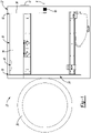
Figure 1 is a side elevation view of an exemplary washer and dryer combination appliance where the washer and dryer combination appliance includes an appliance housing and an appliance door that are shown in broken lines; -
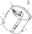
Figure 2 is a front perspective view of an exemplary sub-assembly of the washer and dryer combination appliance illustrated inFigure 1 ; -
Figure 3 is a rear perspective view of an exemplary sub-assembly of the washer and dryer combination appliance illustrated inFigure 1 ; -
Figure 4 is a perspective section view of an exemplary sub-assembly of the washer and dryer combination appliance illustrated inFigure 1 ; -
Figure 5 is an enlarged section view of the exemplary sub-assembly illustrated inFigure 4 where an exemplary dynamic, expandable seal is shown in an extended position; -
Figure 6 is an enlarged section view of the exemplary sub-assembly illustrated inFigure 4 where the exemplary dynamic, expandable seal is shown in a retracted position; -
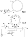
Figure 7 is a schematic diagram of an exemplary dynamic, expandable seal that operates as a close loop system; -
Figure 8 is a schematic diagram of another exemplary dynamic, expandable seal that operates as an open loop system; and -
Figure 9 is a schematic diagram of another exemplary dynamic, expandable seal that is made of a thermally expandable material. - Referring to the Figures, wherein like numerals indicate corresponding parts throughout the several views, a washer and
dryer combination appliance 20 is illustrated. - Example embodiments will now be described more fully with reference to the accompanying drawings. Example embodiments are provided so that this disclosure will be thorough, and will fully convey the scope to those who are skilled in the art. Numerous specific details are set forth such as examples of specific components, devices, and methods, to provide a thorough understanding of embodiments of the present disclosure. It will be apparent to those skilled in the art that specific details need not be employed, that example embodiments may be embodied in many different forms and that neither should be construed to limit the scope of the disclosure. In some example embodiments, well-known processes, well-known device structures, and well-known technologies are not described in detail.
- The terminology used herein is for the purpose of describing particular example embodiments only and is not intended to be limiting. As used herein, the singular forms "a," "an," and "the" may be intended to include the plural forms as well, unless the context clearly indicates otherwise. The terms "comprises," "comprising," "including," and "having," are inclusive and therefore specify the presence of stated features, integers, steps, operations, elements, and/or components, but do not preclude the presence or addition of one or more other features, integers, steps, operations, elements, components, and/or groups thereof. The method steps, processes, and operations described herein are not to be construed as necessarily requiring their performance in the particular order discussed or illustrated, unless specifically identified as an order of performance. It is also to be understood that additional or alternative steps may be employed.
- When an element or layer is referred to as being "on," "engaged to," "connected to," or "coupled to" another element or layer, it may be directly on, engaged, connected or coupled to the other element or layer, or intervening elements or layers may be present. In contrast, when an element is referred to as being "directly on," "directly engaged to," "directly connected to," or "directly coupled to" another element or layer, there may be no intervening elements or layers present. Other words used to describe the relationship between elements should be interpreted in a like fashion (e.g., "between" versus "directly between," "adjacent" versus "directly adjacent," etc.). As used herein, the term "and/or" includes any and all combinations of one or more of the associated listed items.
- Although the terms first, second, third, etc. may be used herein to describe various elements, components, regions, layers and/or sections, these elements, components, regions, layers and/or sections should not be limited by these terms. These terms may be only used to distinguish one element, component, region, layer or section from another region, layer or section. Terms such as "first," "second," and other numerical terms when used herein do not imply a sequence or order unless clearly indicated by the context. Thus, a first element, component, region, layer or section discussed below could be termed a second element, component, region, layer or section without departing from the teachings of the example embodiments.
- For purposes of description herein the terms "up," "down," "above," "below," "upper," "lower," "top," "bottom," "front," "rear," and derivatives thereof shall relate to the assembly as oriented in
Figures 1-9 . However, it is to be understood that the apparatus and assemblies described herein may assume various alternative orientations. - With reference to
Figure 1 , a washer anddryer combination appliance 20 having a front-load configuration is illustrated. The washer anddryer combination appliance 20 includes an appliance housing 22 that is rectangular in shape and that includes afront opening 24. Anappliance door 26 is pivotally connected to the appliance housing 22. Theappliance door 26 swings between an open position and a closed position. In the closed position, theappliance door 26 shuts or closes thefront opening 24 in the appliance housing 22. - With additional reference to
Figures 2-4 , adrum housing 28 having a cylindrical shape is fixedly mounted inside the appliance housing 22. Thedrum housing 28 extends longitudinally between afront housing end 30 and arear housing end 32. Thedrum housing 28 includes ahousing opening 34 at thefront housing end 30, arear housing wall 36 at therear housing end 32, and ahousing sidewall 38 that extends longitudinally between the front and rear housing ends 30, 32. Thefront housing end 30, thehousing sidewall 38, and therear housing wall 36 cooperate to define ahousing cavity 40 inside thedrum housing 28. Therear housing wall 36 has a disc shape and includes an air inlet opening 42 at a twelve o'clock position that is arranged in fluid communication with thehousing cavity 40 and anair inlet duct 44 in the appliance housing 22. Thehousing sidewall 38 includes an air outlet opening 46 that is positioned near thefront housing end 30 at the twelve o'clock position. - A
drum 48 is positioned in thehousing cavity 40 such that thedrum 48 is rotatable with respect to thedrum housing 28 about a longitudinal axis A. Thedrum 48 also has a cylindrical shape and extends longitudinally between afront drum end 50 and arear drum end 52. Thedrum 48 includes adrum opening 54 at thefront drum end 50, arear drum wall 64 at therear drum end 52, and adrum sidewall 56 that extends longitudinally between the front and rear drum ends 50, 52. Thefront drum end 50, thedrum sidewall 56, and therear drum wall 64 cooperate to define alaundry compartment 58 inside thedrum 48. Thefront opening 24 of the appliance housing 22, thehousing opening 34 at thefront housing end 30, and thedrum opening 54 at thefront drum end 50 are substantially aligned with one another and therefore provide access to thelaundry compartment 58 inside thedrum 48 when theappliance door 26 is in the open position. Thus, it should be appreciated that in use, laundry (e.g., clothes, towels, and bedding) is placed inside thelaundry compartment 58 where it is first cleaned during a wash cycle and then dried during a drying cycle. - A
drive shaft 60 that is fixedly coupled to thedrum 48 extends co-axially along the longitudinal axis A and through therear housing wall 36. Thedrive shaft 60 is supported by a bearingpack 62 that is mounted in therear housing wall 36 such that thedrive shaft 60 and thedrum 48 rotate together as a single unit within the appliance housing 22. A motor (not shown) is positioned in the appliance housing 22 and is coupled to thedrive shaft 60. The motor drives rotation of thedrive shaft 60 and thedrum 48 relative to thedrum housing 28 and the appliance housing 22 during operation of the washer anddryer combination appliance 20, such as during washing and tumbling. - With additional reference to
Figures 5 and 6 , therear drum wall 64 has a disc shape and anouter perimeter 66.Perforations 68 extend through therear drum wall 64 and permit air to flow into thelaundry compartment 58 from thehousing cavity 40. Anair gap 70 is provided between therear housing wall 36 and therear drum wall 64. Both a primaryair flow path 72 and a bypassair flow path 74 exist inside thedrum housing 28 due to theair gap 70 between therear housing wall 36 and therear drum wall 64 and the clearances between thehousing sidewall 38 and thedrum sidewall 56. In the primaryair flow path 72, air flows through the air inlet opening 42 in therear housing wall 36 and into theair gap 70, through theperforations 68 in therear drum wall 64 and into thelaundry compartment 58, through thedrum opening 54 at thefront drum end 50, into thehousing cavity 40, and out through the air outlet opening 46 in thehousing sidewall 38. Air flowing through the primaryair flow path 72 therefore helps dry wet laundry in thelaundry compartment 58. In the bypassair flow path 74, air flows through the air inlet opening 42 in therear housing wall 36, into theair gap 70, and then radially outwardly around therear drum wall 64 and into the space between thehousing sidewall 38 and thedrum sidewall 56. From there, the air flows out through the air outlet opening 46 in thehousing sidewall 38 without passing through thelaundry compartment 58. Air flowing through the bypassair flow path 74 does not meaningfully contribute to drying and is therefore unwanted. The washer anddryer combination appliance 20 disclosed herein includes a dynamic,expandable seal 76 to minimize and/or block the bypassair flow path 74 during the drying cycle. - The dynamic,
expandable seal 76, is actuatable between a retracted position and an extended position. In the extended position, the dynamic,expandable seal 76 extends across theair gap 70 to either completely or partially block the bypassair flow path 74. In the illustrated example, the dynamic,expandable seal 76 is positioned adjacent to theouter perimeter 66 of therear drum wall 64 and, in the extended position, creates a sealedregion 78 in theair gap 70 around the air inlet opening 42 in therear housing wall 36. As such, the dynamic,expandable seal 76 directs all or substantially all of the air that enters the sealedregion 78 through theperforations 68 in therear drum wall 64 and into thelaundry compartment 58 when the dynamic,expandable seal 76 is in the extended position. - The
air gap 70 has anominal width 80 that equals a distance between therear housing wall 36 and therear drum wall 64. It should be appreciated that the width of theair gap 70 may vary depending on the location and thedrum 48 may be configured to move longitudinally relative to drumhousing 28 during operation of the washer anddryer combination appliance 20 due to unbalanced loads of laundry in thelaundry compartment 58 or other operating variables. Therefore, it should be understood that thenominal width 80 of theair gap 70, as the term is used herein, refers to the distance between therear housing wall 36 and therear drum wall 64 at the location of the dynamic,expandable seal 76 when thedrum 48 is in its rest position (i.e., naturally biased position) within thedrum housing 28. - The dynamic,
expandable seal 76 may be attached to either therear housing wall 36 or therear drum wall 64 and has an expandedwidth 82 that extends across at least ninety percent (90%) of thenominal width 80 of theair gap 70 when the dynamic,expandable seal 76 is in the extended position. In the illustrated example, the dynamic,expandable seal 76 is attached to (i.e., is mounted to) therear housing wall 36 and is configured to contact theouter perimeter 66 of therear drum wall 64 when the dynamic,expandable seal 76 is in the extended position and thedrum 48 is in its rest position. As such, in the illustrated example, the expandedwidth 82 of the dynamic,expandable seal 76 equals thenominal width 80 of theair gap 70 when the dynamic,expandable seal 76 is in the extended position. However, nothing in this description should be read as requiring the dynamic,expandable seal 76 to remain in contact with therear drum wall 64 in the extended position during all possible movements of thedrum 48 during operation of the washer anddryer combination appliance 20. -
Figure 5 illustrates the dynamic,expandable seal 76 in the extended position whileFigure 6 illustrates the dynamic,expandable seal 76 in the retracted position. The dynamic,expandable seal 76 has aninboard face 84 that contacts therear drum wall 64 when the dynamic,expandable seal 76 is in the extended position (Figure 5 ) and anoutboard face 86 that is fixedly attached to therear housing wall 36. Theinboard face 84 of the dynamic,expandable seal 76 is spaced away from therear drum wall 64 when the dynamic,expandable seal 76 is in the retracted position (Figure 6 ). As such, the dynamic,expandable seal 76 does not rotate with thedrum 48 during operation of the washer anddryer combination appliance 20 and does not introduce (i.e., add) any drag on thedrum 48 in the retracted position. This is important because such drag on thedrum 48 could trigger alarms during the wash cycle, for example. Torque on the motor may be used to determine off-balance loads during the wash cycle. Drag on thedrum 48 increases torque on the motor, which is more problematic during the wash cycle where rotational speeds are higher. For example, during a wash cycle, the motor may spin thedrum 48 at speeds up to 1,000 revolutions per minute (rpm). By contrast, the motor may only spin thedrum 48 at speeds of 50-55 revolutions per minute (rpm) during the drying cycle. In addition, torque on the motor is greater during the wash cycle because the laundry in thelaundry compartment 58 is saturated (i.e., wet) and is therefore heavier than the same load of laundry will be during the drying cycle. - Still referring to
Figures 5 and 6 , theinboard face 84 of the dynamic,expandable seal 76 includes awear surface 88 that has a multi-layer construction and is made of an abrasion resistant material. By way of example and without limitation, the dynamic,expandable seal 76 may include a layer that is made of rubber and thewear surface 88 of the dynamic,expandable seal 76 may include another layer that is made of plastic or felt. It should also be appreciated that the dynamic,expandable seal 76 may alternatively be arranged where theinboard face 84 of the dynamic,expandable seal 76 is fixedly attached to therear drum wall 64 and theoutboard face 86 of the dynamic,expandable seal 76 is spaced away from therear housing wall 36 when the dynamic,expandable seal 76 is in the retracted position. In accordance with this alternative arrangement (not illustrated), the dynamic,expandable seal 76 rotates with thedrum 48 during operation of the washer anddryer combination appliance 20. In this arrangement, theinboard face 84 of the dynamic,expandable seal 76 may include thewear surface 88. -
Figures 7-9 illustrate different configurations and actuation systems for the dynamic,expandable seal 76 illustrated inFigures 1-6 . In each embodiment illustrated inFigures 7-9 , acontroller expandable seal controller expandable seal dryer combination appliance 20 in order to direct/force as much air as possible along the primaryair flow path 72 through thedrum 48 for improved drying and efficiency. By contrast, thecontroller expandable seal dryer combination appliance 20 to prevent the dynamic,expandable seal drum 48, which could result in alarms, faults, and/or damage to the motor. As a result, the dynamic,expandable seals dryer combination appliance 20 without having to re-calibrate, re-program, or re-design the operating parameters of the motor and associated electronics, including pre-existing alarms and fault codes. -
Figure 7 illustrates a dynamic,expandable seal 176 that is configured as a close loop system with apiston 192. In this configuration, the dynamic,expandable seal 176 is tubular and has a ring-like shape. In other words, the dynamic,expandable seal 176 includes abladder 194 and extends in a continuous circle about the longitudinal axis A. Thebladder 194 is arranged in fluid communication with thepiston 192, which is electrically connected to and controlled by thecontroller 190. Both thebladder 194 of the dynamic,expandable seal 176 and a workingchamber 196 of thepiston 192 are filled with a fluid, such as air, water, hydraulic fluid, or oil. Thepiston 192 pushes fluid into thebladder 194 to actuate (i.e., inflate) the dynamic,expandable seal 176 and places the dynamic,expandable seal 176 in the extended position. By contrast, thepiston 192 pulls fluid out of thebladder 194 to actuate (i.e., deflate) the dynamic,expandable seal 176 and places the dynamic,expandable seal 176 in the retracted position. Thus, in this configuration, the dynamic,expandable seal 176 is an inflatable seal. -
Figure 8 illustrates a dynamic,expandable seal 276 that is configured as an open loop system with aninlet valve 298 and/or apump 200 and anoutlet valve 202, all of which are electrically connected to and controlled by thecontroller 290. In this configuration, the dynamic,expandable seal 276 is tubular and extends across amajor arc length 204. It should be appreciated that this term refers to an arc or semi-circle that is greater than 180 degrees, but less than 360 degrees. The dynamic,expandable seal 276 includes afirst end 206 and asecond end 208 that are positioned on opposing sides of abreak 210 in the dynamic,expandable seal 76. Thebreak 210 in the dynamic,expandable seal 276 is aligned with a six o'clock position relative to the longitudinal axis A and permits fluid and debris to drain from the sealedregion 278. Once again, the dynamic,expandable seal 276 includes abladder 294 that is arranged in fluid communication with theinlet valve 298 or thepump 200 at thefirst end 206 and theoutlet valve 202 at thesecond end 208. When thecontroller 290 opens theinlet valve 298 and/or activates thepump 200, fluid is pushed into thebladder 294 to actuate (i.e., inflate) the dynamic,expandable seal 276 and place the dynamic,expandable seal 276 in the extended position. By contrast, when thecontroller 290 opens theoutlet valve 202, fluid flows out of (i.e., leaves) thebladder 294 to actuate (i.e., deflate) the dynamic,expandable seal 276 and place the dynamic,expandable seal 276 in the retracted position. So the dynamic,expandable seal 276 is an inflatable seal in this configuration as well. -
Figure 9 illustrates a dynamic,expandable seal 376 that is configured as a thermal expansion device. For example, the dynamic,expandable seal 376 may be made of a thermally expandable material where an increase in temperature in the thermally expandable material causes the dynamic,expandable seal 376 to expand to the extended position and a decrease in temperature in the thermally expandable material causes the dynamic,expandable seal 376 to retract / contract to the retracted position. Alternatively, the dynamic,expandable seal 376 may include a bladder that is filled with a thermally expandable material, such as a thermally expandable fluid. In either arrangement, the dynamic,expandable seal 376 may include one or more heating coils 312 that are electrically connected to thecontroller 390. When thecontroller 390 activates the heating coils 312, the thermally expandable material expands to actuate the dynamic,expandable seal 376 and places the dynamic,expandable seal 376 in the extended position. By contrast, when thecontroller 390 deactivates the heating coils 312, the thermally expandable material contracts to actuate the dynamic,expandable seal 376 and places the dynamic,expandable seal 376 in the retracted position. - Many modifications and variations of the apparatus and assemblies described in the present disclosure are possible in light of the above teachings and may be practiced otherwise than as specifically described while within the scope of the appended claims. These antecedent recitations should be interpreted to cover any combination in which the inventive novelty exercises its utility.
Claims (15)
- An apparatus for a washer and dryer combination appliance (20), comprising:a drum housing (28) including a front housing end (30) with a housing opening (34) and a rear housing end (32) with a rear housing wall (36);a drum (48) positioned in and rotatable with respect to said drum housing (28), said drum (48) including a front drum end (50) with a drum opening (54), a rear drum end (52) with a rear drum wall (64), and a laundry compartment (58) located inside said drum (48);said rear drum wall (64) having perforations (68) that permit air to flow into said laundry compartment (58);an air gap (70) located between said rear housing wall (36) and said rear drum wall (64); anda dynamic, expandable seal (76), attached to one of said rear housing wall (36) and said rear drum wall (64), that is actuatable between a retracted position and an extended position,wherein said dynamic, expandable seal (76) extends across at least part of said air gap (70) in said extended position to direct airflow through said perforations (68) in said rear drum wall (64).
- The apparatus as set forth in claim 1, wherein said dynamic, expandable seal (76) includes an inboard face (84) that contacts said rear drum wall (64) when said dynamic, expandable seal (76) is in said extended position and an outboard face (86) that contacts said rear housing wall (36) when said dynamic, expandable seal (76) is in said extended position.
- The apparatus as set forth in claim 2, wherein said outboard face (86) of said dynamic, expandable seal (76) is fixedly attached to said rear housing wall (36) and said inboard face (84) of said dynamic, expandable seal (76) is spaced away from said rear drum wall (64) when said dynamic, expandable seal (76) is in said retracted position such that said dynamic, expandable seal (76) does not rotate with said drum (48) during operation of said washer and dryer combination appliance (20).
- The apparatus as set forth in claim 2, wherein said inboard face (84) of said dynamic, expandable seal (76) is fixedly attached to said rear drum wall (64) and said outboard face (86) of said dynamic, expandable seal (76) is spaced away from said rear housing wall (36) when said dynamic, expandable seal (76) is in said retracted position such that said dynamic, expandable seal (76) rotates with said drum (48) during operation of said washer and dryer combination appliance (20).
- The apparatus according to claims 3 or 4, wherein said dynamic, expandable seal (76) includes a wear surface (88) that is made of an abrasion resistant material.
- The apparatus as set forth in claim 5, wherein said wear surface (88) has a multi-layer construction.
- The apparatus according to any one of the preceding claims, further comprising:
a controller (90) configured to actuate said dynamic, expandable seal (76), wherein said controller (90) is programmed to place said dynamic, expandable seal (76) in said extended position during a drying cycle of said washer and dryer combination appliance (20) and place said dynamic, expandable seal (76) in said retracted position during a wash cycle of said washer and dryer combination appliance (20). - The apparatus according to any one of the preceding claims, wherein said rear housing wall (36) has an air inlet opening (42) and wherein said dynamic, expandable seal (76), in said extended position, creates a sealed region (78) around said air inlet opening (42) such that said dynamic, expandable seal (76) directs said air through said perforations (68) in said rear drum wall (64) and into said laundry compartment (58) and blocks said air from flowing radially outwardly and around said drum (48) when said dynamic, expandable seal (76) is in said extended position.
- The apparatus according to any one of the preceding claims, wherein said air gap (70) has a nominal width (80) equaling a distance between said rear housing wall (36) and said rear drum wall (64) and wherein said dynamic, expandable seal (76) has an expanded width (82) that extends across at least ninety percent of said nominal width (80) of said air gap (70) when said dynamic, expandable seal (76) is in said expanded position.
- The apparatus according to any one of the preceding claims, wherein said dynamic, expandable seal (76) is positioned adjacent to an outer perimeter (66) of said rear drum wall (64).
- The apparatus according to any one of the preceding claims, wherein said dynamic, expandable seal (76, 176) is tubular.
- The apparatus according to any one of the preceding claims, wherein said dynamic, expandable seal (276) includes a bladder (294) that is arranged in fluid communication with a pump (200) that is configured to inflate and deflate said bladder (294) with a fluid.
- The apparatus according to any one of claims 1-11, wherein said dynamic, expandable seal (376) is made of a thermally expandable material wherein an increase in temperature in said thermally expandable material causes said dynamic, expandable seal (376) to expand to said extended position and a decrease in temperature in said thermally expandable material causes said dynamic, expandable seal (376) to retract to said retracted position.
- The apparatus according to any one of the preceding claims, wherein said dynamic, expandable seal (76, 176) extends in a continuous circle and has a ring-like shape.
- The apparatus according to any one of claims 1-13, wherein said dynamic, expandable seal (276, 376) extends across a major arc length (204) and includes a first end (206) and a second end (208) positioned on opposing sides of a break (210) in said dynamic, expandable seal (276, 376).
Applications Claiming Priority (1)
| Application Number | Priority Date | Filing Date | Title |
|---|---|---|---|
| US17/240,056 US11821124B2 (en) | 2021-04-26 | 2021-04-26 | Dynamic seal for washer and dryer combination appliance |
Publications (1)
| Publication Number | Publication Date |
|---|---|
| EP4083297A1 true EP4083297A1 (en) | 2022-11-02 |
Family
ID=81306760
Family Applications (1)
| Application Number | Title | Priority Date | Filing Date |
|---|---|---|---|
| EP22167484.9A Withdrawn EP4083297A1 (en) | 2021-04-26 | 2022-04-08 | Dynamic seal for washer and dryer combination appliance |
Country Status (3)
| Country | Link |
|---|---|
| US (1) | US11821124B2 (en) |
| EP (1) | EP4083297A1 (en) |
| CN (1) | CN115323721A (en) |
Cited By (1)
| Publication number | Priority date | Publication date | Assignee | Title |
|---|---|---|---|---|
| IT202400006385A1 (en) * | 2024-03-22 | 2025-09-22 | Antonio Francesco Chiriatti | WASHING MACHINE DRYER WITH A DRUM DEVICE THAT IMPROVES DRYING. |
Families Citing this family (1)
| Publication number | Priority date | Publication date | Assignee | Title |
|---|---|---|---|---|
| US11821124B2 (en) * | 2021-04-26 | 2023-11-21 | Whirlpool Corporation | Dynamic seal for washer and dryer combination appliance |
Citations (5)
| Publication number | Priority date | Publication date | Assignee | Title |
|---|---|---|---|---|
| JP4785775B2 (en) * | 2006-08-08 | 2011-10-05 | 三菱電機株式会社 | Washing machine |
| WO2014181493A1 (en) * | 2013-05-07 | 2014-11-13 | パナソニックIpマネジメント株式会社 | Washing and drying machine |
| WO2016050295A1 (en) * | 2014-10-01 | 2016-04-07 | Arcelik Anonim Sirketi | Laundry drying machine having a structurally improved leak-proofing system |
| US20160101303A1 (en) * | 2011-11-22 | 2016-04-14 | Owens Corning Intellectual Capital, Llc | Nonwoven material and dryer with nonwoven material |
| EP3919665A1 (en) * | 2020-06-03 | 2021-12-08 | Haier Deutschland GmbH | Dryer for drying laundry and method of operating a dryer |
Family Cites Families (16)
| Publication number | Priority date | Publication date | Assignee | Title |
|---|---|---|---|---|
| US3875686A (en) * | 1974-01-28 | 1975-04-08 | Schlegel Mfg Co | Seal for clothes dryer |
| JP4541023B2 (en) | 2004-04-26 | 2010-09-08 | パナソニック株式会社 | Washing and drying machine |
| JP2007117277A (en) * | 2005-10-26 | 2007-05-17 | Sanyo Electric Co Ltd | Washing/dewatering/drying machine |
| WO2007148746A1 (en) | 2006-06-23 | 2007-12-27 | Mitsubishi Electric Corporation | Washing machine |
| DE102007002181B3 (en) * | 2007-01-15 | 2008-08-21 | BSH Bosch und Siemens Hausgeräte GmbH | Condensation dryer with a heat pump |
| JP2008220817A (en) * | 2007-03-15 | 2008-09-25 | Sanyo Electric Co Ltd | Washing and drying machine |
| CN101343826B (en) * | 2008-01-23 | 2010-08-11 | 松下家电研究开发(杭州)有限公司 | Washing machine with drying device |
| US8572862B2 (en) * | 2010-10-25 | 2013-11-05 | Battelle Memorial Institute | Open-loop heat-recovery dryer |
| EP2573252B1 (en) * | 2011-09-26 | 2014-05-07 | Electrolux Home Products Corporation N.V. | Laundry treatment apparatus with heat pump |
| ITMI20130845A1 (en) * | 2013-05-24 | 2014-11-25 | Eni Spa | EMERGENCY VALVE ASSEMBLY FOR EXTRACTIVE WELLS, WELL EQUIPPED WITH THIS VALVE AND PROCEDURE TO MANAGE WITH THIS VALVE AN EXTRACTIVE WELL IN EMERGENCY CONDITIONS |
| KR101588137B1 (en) * | 2014-10-24 | 2016-01-22 | 엘지전자 주식회사 | Drain pump assembly and dryer for clothes having the same |
| CN105986429B (en) * | 2015-02-04 | 2019-11-05 | 青岛海尔洗衣机有限公司 | A kind of drainage control mechanism and washing machine of washing machine inner tub |
| JP2018046887A (en) * | 2016-09-20 | 2018-03-29 | パナソニックIpマネジメント株式会社 | Drum-type washing machine |
| US10662574B2 (en) * | 2017-02-27 | 2020-05-26 | Whirlpool Corporation | Self cleaning heater exchanger plate |
| US10765974B2 (en) * | 2019-01-25 | 2020-09-08 | Haier Us Appliance Solutions, Inc. | Lint collection assembly for a dryer appliance |
| US11821124B2 (en) * | 2021-04-26 | 2023-11-21 | Whirlpool Corporation | Dynamic seal for washer and dryer combination appliance |
-
2021
- 2021-04-26 US US17/240,056 patent/US11821124B2/en active Active
-
2022
- 2022-04-08 EP EP22167484.9A patent/EP4083297A1/en not_active Withdrawn
- 2022-04-26 CN CN202210445020.4A patent/CN115323721A/en active Pending
Patent Citations (5)
| Publication number | Priority date | Publication date | Assignee | Title |
|---|---|---|---|---|
| JP4785775B2 (en) * | 2006-08-08 | 2011-10-05 | 三菱電機株式会社 | Washing machine |
| US20160101303A1 (en) * | 2011-11-22 | 2016-04-14 | Owens Corning Intellectual Capital, Llc | Nonwoven material and dryer with nonwoven material |
| WO2014181493A1 (en) * | 2013-05-07 | 2014-11-13 | パナソニックIpマネジメント株式会社 | Washing and drying machine |
| WO2016050295A1 (en) * | 2014-10-01 | 2016-04-07 | Arcelik Anonim Sirketi | Laundry drying machine having a structurally improved leak-proofing system |
| EP3919665A1 (en) * | 2020-06-03 | 2021-12-08 | Haier Deutschland GmbH | Dryer for drying laundry and method of operating a dryer |
Cited By (1)
| Publication number | Priority date | Publication date | Assignee | Title |
|---|---|---|---|---|
| IT202400006385A1 (en) * | 2024-03-22 | 2025-09-22 | Antonio Francesco Chiriatti | WASHING MACHINE DRYER WITH A DRUM DEVICE THAT IMPROVES DRYING. |
Also Published As
| Publication number | Publication date |
|---|---|
| US20220341074A1 (en) | 2022-10-27 |
| US11821124B2 (en) | 2023-11-21 |
| CN115323721A (en) | 2022-11-11 |
Similar Documents
| Publication | Publication Date | Title |
|---|---|---|
| JP5827070B2 (en) | Drum washing machine | |
| JP4635081B2 (en) | Laundry dryer and dryer | |
| US11821124B2 (en) | Dynamic seal for washer and dryer combination appliance | |
| JPH02305593A (en) | Full automatic washing machine and dryer | |
| JP6212701B2 (en) | Washing and drying machine | |
| CN101187119A (en) | Drum Washer Dryer | |
| JP4020820B2 (en) | Washing and drying machine | |
| JP2003311067A (en) | Washing and drying machine | |
| JP4541023B2 (en) | Washing and drying machine | |
| JP2011200365A (en) | Washing and drying machine | |
| US20050138973A1 (en) | Washing machine with drying function | |
| JP5556578B2 (en) | Drum type washer / dryer | |
| JP3539382B2 (en) | Washing and drying machine | |
| CN100526541C (en) | Drum washing machine and drum washing and drying machine | |
| JP5146472B2 (en) | Washing and drying machine | |
| WO2006059440A1 (en) | Washer-dryer | |
| JP4038227B2 (en) | Drum washing machine | |
| JPH10263265A (en) | Drum type washing machine | |
| JP4745141B2 (en) | Washing and drying machine | |
| KR100733298B1 (en) | Drying Washer | |
| JP7015996B2 (en) | washing machine | |
| JP3473574B2 (en) | Washing and drying machine | |
| JP3991757B2 (en) | Dry washing machine | |
| JP7106506B2 (en) | washing machine | |
| JP3894845B2 (en) | Drum washing machine |
Legal Events
| Date | Code | Title | Description |
|---|---|---|---|
| PUAI | Public reference made under article 153(3) epc to a published international application that has entered the european phase |
Free format text: ORIGINAL CODE: 0009012 |
|
| STAA | Information on the status of an ep patent application or granted ep patent |
Free format text: STATUS: THE APPLICATION HAS BEEN PUBLISHED |
|
| AK | Designated contracting states |
Kind code of ref document: A1 Designated state(s): AL AT BE BG CH CY CZ DE DK EE ES FI FR GB GR HR HU IE IS IT LI LT LU LV MC MK MT NL NO PL PT RO RS SE SI SK SM TR |
|
| RAP3 | Party data changed (applicant data changed or rights of an application transferred) |
Owner name: WHIRLPOOL CORPORATION |
|
| STAA | Information on the status of an ep patent application or granted ep patent |
Free format text: STATUS: REQUEST FOR EXAMINATION WAS MADE |
|
| 17P | Request for examination filed |
Effective date: 20230426 |
|
| RBV | Designated contracting states (corrected) |
Designated state(s): AL AT BE BG CH CY CZ DE DK EE ES FI FR GB GR HR HU IE IS IT LI LT LU LV MC MK MT NL NO PL PT RO RS SE SI SK SM TR |
|
| GRAP | Despatch of communication of intention to grant a patent |
Free format text: ORIGINAL CODE: EPIDOSNIGR1 |
|
| STAA | Information on the status of an ep patent application or granted ep patent |
Free format text: STATUS: GRANT OF PATENT IS INTENDED |
|
| INTG | Intention to grant announced |
Effective date: 20241028 |
|
| STAA | Information on the status of an ep patent application or granted ep patent |
Free format text: STATUS: THE APPLICATION IS DEEMED TO BE WITHDRAWN |
|
| 18D | Application deemed to be withdrawn |
Effective date: 20250301 |