EP4082858B1 - Verfahren und vorrichtung zur aggregation/repräsentation eines umgebungsmodells für ein fahrerassistenzsystem eines fahrzeugs - Google Patents
Verfahren und vorrichtung zur aggregation/repräsentation eines umgebungsmodells für ein fahrerassistenzsystem eines fahrzeugs Download PDFInfo
- Publication number
- EP4082858B1 EP4082858B1 EP21170962.1A EP21170962A EP4082858B1 EP 4082858 B1 EP4082858 B1 EP 4082858B1 EP 21170962 A EP21170962 A EP 21170962A EP 4082858 B1 EP4082858 B1 EP 4082858B1
- Authority
- EP
- European Patent Office
- Prior art keywords
- vehicle
- reference point
- trajectory
- coordinate system
- environment
- Prior art date
- Legal status (The legal status is an assumption and is not a legal conclusion. Google has not performed a legal analysis and makes no representation as to the accuracy of the status listed.)
- Active
Links
Images


Classifications
-
- B—PERFORMING OPERATIONS; TRANSPORTING
- B60—VEHICLES IN GENERAL
- B60W—CONJOINT CONTROL OF VEHICLE SUB-UNITS OF DIFFERENT TYPE OR DIFFERENT FUNCTION; CONTROL SYSTEMS SPECIALLY ADAPTED FOR HYBRID VEHICLES; ROAD VEHICLE DRIVE CONTROL SYSTEMS FOR PURPOSES NOT RELATED TO THE CONTROL OF A PARTICULAR SUB-UNIT
- B60W40/00—Estimation or calculation of non-directly measurable driving parameters for road vehicle drive control systems not related to the control of a particular sub unit, e.g. by using mathematical models
- B60W40/02—Estimation or calculation of non-directly measurable driving parameters for road vehicle drive control systems not related to the control of a particular sub unit, e.g. by using mathematical models related to ambient conditions
-
- B—PERFORMING OPERATIONS; TRANSPORTING
- B60—VEHICLES IN GENERAL
- B60W—CONJOINT CONTROL OF VEHICLE SUB-UNITS OF DIFFERENT TYPE OR DIFFERENT FUNCTION; CONTROL SYSTEMS SPECIALLY ADAPTED FOR HYBRID VEHICLES; ROAD VEHICLE DRIVE CONTROL SYSTEMS FOR PURPOSES NOT RELATED TO THE CONTROL OF A PARTICULAR SUB-UNIT
- B60W30/00—Purposes of road vehicle drive control systems not related to the control of a particular sub-unit, e.g. of systems using conjoint control of vehicle sub-units
- B60W30/08—Active safety systems predicting or avoiding probable or impending collision or attempting to minimise its consequences
- B60W30/095—Predicting travel path or likelihood of collision
-
- B—PERFORMING OPERATIONS; TRANSPORTING
- B60—VEHICLES IN GENERAL
- B60W—CONJOINT CONTROL OF VEHICLE SUB-UNITS OF DIFFERENT TYPE OR DIFFERENT FUNCTION; CONTROL SYSTEMS SPECIALLY ADAPTED FOR HYBRID VEHICLES; ROAD VEHICLE DRIVE CONTROL SYSTEMS FOR PURPOSES NOT RELATED TO THE CONTROL OF A PARTICULAR SUB-UNIT
- B60W40/00—Estimation or calculation of non-directly measurable driving parameters for road vehicle drive control systems not related to the control of a particular sub unit, e.g. by using mathematical models
- B60W40/10—Estimation or calculation of non-directly measurable driving parameters for road vehicle drive control systems not related to the control of a particular sub unit, e.g. by using mathematical models related to vehicle motion
-
- B—PERFORMING OPERATIONS; TRANSPORTING
- B60—VEHICLES IN GENERAL
- B60W—CONJOINT CONTROL OF VEHICLE SUB-UNITS OF DIFFERENT TYPE OR DIFFERENT FUNCTION; CONTROL SYSTEMS SPECIALLY ADAPTED FOR HYBRID VEHICLES; ROAD VEHICLE DRIVE CONTROL SYSTEMS FOR PURPOSES NOT RELATED TO THE CONTROL OF A PARTICULAR SUB-UNIT
- B60W50/00—Details of control systems for road vehicle drive control not related to the control of a particular sub-unit, e.g. process diagnostic or vehicle driver interfaces
- B60W50/08—Interaction between the driver and the control system
- B60W50/14—Means for informing the driver, warning the driver or prompting a driver intervention
-
- B—PERFORMING OPERATIONS; TRANSPORTING
- B60—VEHICLES IN GENERAL
- B60W—CONJOINT CONTROL OF VEHICLE SUB-UNITS OF DIFFERENT TYPE OR DIFFERENT FUNCTION; CONTROL SYSTEMS SPECIALLY ADAPTED FOR HYBRID VEHICLES; ROAD VEHICLE DRIVE CONTROL SYSTEMS FOR PURPOSES NOT RELATED TO THE CONTROL OF A PARTICULAR SUB-UNIT
- B60W60/00—Drive control systems specially adapted for autonomous road vehicles
- B60W60/001—Planning or execution of driving tasks
- B60W60/0027—Planning or execution of driving tasks using trajectory prediction for other traffic participants
-
- B—PERFORMING OPERATIONS; TRANSPORTING
- B60—VEHICLES IN GENERAL
- B60W—CONJOINT CONTROL OF VEHICLE SUB-UNITS OF DIFFERENT TYPE OR DIFFERENT FUNCTION; CONTROL SYSTEMS SPECIALLY ADAPTED FOR HYBRID VEHICLES; ROAD VEHICLE DRIVE CONTROL SYSTEMS FOR PURPOSES NOT RELATED TO THE CONTROL OF A PARTICULAR SUB-UNIT
- B60W50/00—Details of control systems for road vehicle drive control not related to the control of a particular sub-unit, e.g. process diagnostic or vehicle driver interfaces
- B60W50/08—Interaction between the driver and the control system
- B60W50/14—Means for informing the driver, warning the driver or prompting a driver intervention
- B60W2050/146—Display means
-
- B—PERFORMING OPERATIONS; TRANSPORTING
- B60—VEHICLES IN GENERAL
- B60W—CONJOINT CONTROL OF VEHICLE SUB-UNITS OF DIFFERENT TYPE OR DIFFERENT FUNCTION; CONTROL SYSTEMS SPECIALLY ADAPTED FOR HYBRID VEHICLES; ROAD VEHICLE DRIVE CONTROL SYSTEMS FOR PURPOSES NOT RELATED TO THE CONTROL OF A PARTICULAR SUB-UNIT
- B60W2554/00—Input parameters relating to objects
- B60W2554/80—Spatial relation or speed relative to objects
Definitions
- the present invention relates to a method of parametrizing an environment model for a driver assistance system of a vehicle, to an apparatus for parametrizing an environment model for a driver assistance system of a vehicle and to a vehicle comprising said apparatus.
- driver assistant systems such as ACC (Adaptive Cruise Control), AEBS (Advanced Emergency Braking System) and others
- ACC Adaptive Cruise Control
- AEBS Advanced Emergency Braking System
- the driver as well as the environment with a certain variance define the future state of the ego vehicle.
- those systems consider one or more hypotheses of the predicted vehicle state for a certain prediction time period.
- CN112550287 A discloses a driving risk assessment method for a structured road comprising the steps: carrying out the parametric modeling of a reference road center line based on discrete road point information and obtaining a front road model; based on the road model, positioning an obstacle under a Fraent-Serret coordinate system through a vector orthogonal method and reducing the dimension of an actual road traffic scene into a two-dimensional linear road traffic scene; in combination with the road model, the obstacle information and the traffic driving condition, establishing a driving risk quantitative evaluation model reflecting vehicle-road integration, and calculating comprehensive driving risk potential energy to evaluate the driving risk situation.
- road parametric modelling and obstacle coordinate conversion are carried out, an evaluated complex road environment is converted into a straightway environment, algorithm modification work caused by road shape difference is omitted and the robustness and applicability of the algorithm to complex traffic working conditions are enhanced.
- US 10,671,075 B1 discloses a system configured to determine a reference trajectory for an autonomous vehicle to traverse an environment, determine first and second frames associated with the reference trajectory, the second frame associated with a tangent vector of a second point on the reference trajectory, determine a candidate trajectory of the autonomous vehicle, the candidate trajectory including a segment having an origin and a curvature value associated with the position of the autonomous vehicle and intersecting at an intersection point with a reference line that is substantially perpendicular to the tangent vector associated with the second point, the intersection point based at least in part on the curvature value.
- This object is achieved by a method of parametrizing an environment model for a driver assistance system of a vehicle, by an apparatus for parametrizing an environment model for a driver assistance system of a vehicle and by a vehicle comprising said apparatus according to the main claims.
- a reduction of the complexity of an environment model for driver assistant systems can be achieved.
- this can be achieved by transforming a vehicle's driving situation into a coordinate system that is tangential in the most relevant area of the ego vehicle lateral trajectory. Consequently, the ego vehicle trajectory can be simplified into a straight movement in the most relevant area.
- the ego vehicle trajectory is used to determine possible changes relating to surrounding objects, such as possible collisions, changes in distances and others by means of calculations.
- these calculations may be numerical calculations with reduced complexity which take less computational effort and are less error-prone than conventional solutions. Since such systems can be considered as safety critical, they are also more comprehensible.
- a method of parametrizing an environment model for a driver assistance system of a vehicle comprises the steps of:
- the vehicle may be a motor vehicle, such as a passenger car, utility vehicle or commercial vehicle, for example a truck, bus or the like.
- Parametrizing the environment model may comprise aggregating and/or representing the environment model.
- the environment model may represent an environment of the vehicle, including the predicted trajectory of the vehicle, objects in the environment, object trajectories and additionally or alternatively other environment information, for example one or more hypotheses of the predicted vehicle state for a certain prediction time period.
- a hypothesis of the future vehicle state for the predicted time period which may also be referred to as the predicted trajectory or ego vehicle trajectory, may be estimated using different sources, such as sensor information within the vehicle or ego vehicle, driver monitoring information and additionally or alternatively observed environmental information.
- the predicted trajectory or ego vehicle trajectory may be represented in different ways, such as geometrical driving corridors, sets of states, analytical representations such as polynomial functions, probabilistic representations and others.
- the reference point being defined in relation to the detected object may be understood as the reference point being defined within a predetermined maximum or minimum distance from the object or so as to meet another relative requirement with respect to the object.
- the vehicle coordinate system may be defined by a longitudinal axis of the vehicle and a lateral axis of the vehicle.
- the first coordinate axis may correspond to the longitudinal axis, whereas a second coordinate axis of the vehicle coordinate system may correspond to the lateral axis.
- the parametrization data may exclude a lateral part of the trajectory.
- an intersection point between a simplified object movement path and the trajectory may be ascertained so as to define the reference point.
- the nearest point between a simplified object movement path and the trajectory may be ascertained so as to define the reference point.
- a distance between the object and the vehicle along the first coordinate axis of the vehicle coordinate system may be used as the distance between the vehicle and the reference point along the first coordinate axis of the vehicle coordinate system to define a first position value of the reference point, and a second position value of the reference point relative to a second coordinate axis of the vehicle coordinate system may be ascertained on the basis of the first position value.
- the method may also comprise a step of acquiring sensor data from an interface to an environment sensor of the vehicle, wherein the sensor data represents the environment of the vehicle. Additionally or alternatively the method may also comprise a step of processing the sensor data to detect the object. According to an embodiment, the method may further comprise a step of providing the parametrization data to be output to an interface to the driver assistance system.
- An apparatus for parametrizing an environment model for a driver assistance system of a vehicle comprises:
- the apparatus may be configured to execute an embodiment of the aforementioned method or steps thereof.
- the approach presented here further provides an apparatus configured to perform, control or implement the steps of an embodiment of the aforementioned method in corresponding devices or units.
- the apparatus may be configured to read input signals and to determine and provide output signals using the input signals.
- an input signal may represent a sensor signal readable via an input interface of the apparatus.
- An output signal may represent a control signal or a data signal which can be provided at an output interface of the apparatus.
- the apparatus may be configured to determine the output signals using a processing rule implemented in hardware or in software.
- the apparatus may comprise a logic circuit, an integrated circuit or a software module and may, for example, be realized as a discrete component or be included in a discrete component.
- a vehicle comprises an embodiment of the aforementioned apparatus and the driver assistance system, wherein the apparatus and the driver assistance system are communicatively connected to each other.
- the vehicle may be a motor vehicle, such as a passenger car, utility vehicle or commercial vehicle, for example a truck, bus or the like.
- What is also advantageous is a computer program product having program code which may be stored on a machine-readable carrier, such as semiconductor memory, hard disk or optical memory, and is used for performing the method one of the previously described embodiments, when the program product is executed on a computer or an apparatus.
- a machine-readable carrier such as semiconductor memory, hard disk or optical memory
- Fig. 1 shows a schematic illustration of a vehicle 100 comprising an embodiment of an apparatus 110 for parametrizing an environment model 108 for a driver assistance system 106 of the vehicle 100.
- the vehicle 100 is configured as an autonomous vehicle or a semi-autonomous vehicle, for example.
- the vehicle 100 is a motor vehicle, such as a passenger car, utility vehicle or commercial vehicle, for example a truck, bus or the like.
- Fig. 1 shows a detected object OBJ, which is illustrated so as to represent a person here by way of example only. Furthermore, a trajectory or predicted trajectory T of the vehicle 100 is illustrated in the environment. The trajectory T here is illustrated as a curved line.
- the vehicle 100 also comprises the driver assistance system 106, including the environment model 108.
- the vehicle 100 comprises a plurality of driver assistance systems 106.
- the apparatus 110 and the driver assistance system 106 are communicatively connected to each other.
- the apparatus 110 is configured to parametrize the environment model 108 for the driver assistance system 106 of the vehicle 100.
- the apparatus 110 is configured to execute a method of parametrizing the environment model 108 for the driver assistance system 106 of the vehicle 100, such as a method as described with reference to Fig. 3 .
- the apparatus 110 comprises a defining unit 112, a determining unit and a transforming unit 116.
- the defining unit 112 of the apparatus 110 is configured to define a reference point R on the predicted trajectory T of the vehicle 100.
- the defining unit 112 is configured to define the reference point R in relation to the detected object OBJ in the environment of the vehicle 100.
- in relation to may mean within a predetermined range or pursuant to another geographical or geometric criterion, for example.
- the defining unit 112 also is configured to produce definition data 113 representing the defined reference point R.
- the determining unit 114 of the apparatus 110 is configured to determine an angle ⁇ x between a tangent tan to the trajectory T in the reference point R and a first coordinate axis x of a vehicle coordinate system K.
- the determining unit 114 is also configured to determine a relative distance between the object OBJ and the reference point R with reference to the vehicle coordinate system K, in order to obtain object-related information 115.
- the vehicle coordinate system K comprises the first coordinate axis x and a second coordinate axis y.
- the first coordinate axis x here corresponds to a longitudinal axis of the vehicle 100.
- the second coordinate axis y corresponds to a lateral axis of the vehicle 100.
- the transforming unit 116 of the apparatus 100 is configured to transform the object-related information 115 according to the determined angle ⁇ x to a new coordinate system with its first coordinate axis tangential to the trajectory T in the reference point R, in order to obtain parametrization data 117 for parametrizing the environment model 108.
- the parametrization data 117 represents the trajectory T as a straight movement with respect to the object OBJ.
- the apparatus 110 is configured to provide the parametrization data 117 to be output to an interface or output interface 119 of the apparatus 110 to the driver assistance system 106.
- the apparatus 110 is also configured to acquire sensor data 100 for from an interface or input interface 111 of the apparatus 110 to an environment sensor 102 of the vehicle 100.
- the sensor data 104 represents the environment of the vehicle 100, more specifically the environment in a form as sensed by the environment sensor 102.
- the sensor data 104 also represent the object OBJ if present in the environment.
- the apparatus 110 is also configured to process the sensor data 104 to detect the object OBJ.
- the defining unit 112 is configured to use a distance between the object OBJ and the vehicle 100 along the first coordinate axis x of the vehicle coordinate system K as a distance dx between the vehicle 100 and the reference point R along the first coordinate axis x of the vehicle coordinate system K to define a first position value of the reference point R. Furthermore, the defining unit 112 here is configured to ascertain a second position value of the reference point R relative to the second coordinate axis y of the vehicle coordinate system K on the basis of said first position value.
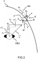
- Fig. 2 shows a schematic illustration of the environment of the vehicle from Fig. 1 at a later parameterization stage.
- Fig. 2 shows the new coordinate system K* with its axes x* and y*, with its first coordinate axis x* aligned with the tangent tan, and a simplified object movement or simplified object movement path v with a first set of components v x and v y pursuant to the vehicle coordinate system K and a second set of components pursuant to the new coordinate system K*.
- the defining unit of the apparatus is configured to ascertain an intersection point between the simplified object movement path v and the trajectory T so as to define the reference point R. Additionally or alternatively, the defining unit of the apparatus is configured to ascertain the nearest point between the simplified object movement path v and the trajectory T so as to define the reference point R.
- the following steps may be executed by the apparatus, for example:
- reference point on the predicted trajectory T in order to estimate the angle ⁇ x to the trajectory T.
- one of the following strategies is used: Use the x distance of the object OBJ as x value of the trajectory T and calculate the y value based on x. Calculate the intersection point between a simplified object movement v with the trajectory T. Calculate the nearest point between a simplified object movement v with the trajectory T.
- the lateral part of the trajectory T can be neglected. This reduces the complexity for the decision making.
- Fig. 3 shows a flowchart of an embodiment of a method 300 of parametrizing an environment model for a driver assistance system of a vehicle.
- the method 300 is executable by the apparatus as described with reference to Fig. 1 or a similar apparatus.
- the method 300 comprises a step 330 of defining, a step 340 of determining and a step 350 of transforming.
- a reference point is defined on a predicted trajectory of the vehicle.
- the reference point is defined in relation to a detected object in an environment of the vehicle.
- an angle between a tangent to the trajectory in the reference point and a first coordinate axis of a vehicle coordinate system and a relative distance between the object and the reference point with reference to the vehicle coordinate system are determined, in order to obtain object-related information.
- the object-related information is transformed according to the determined angle to a new coordinate system with its first coordinate axis tangential to the trajectory in the reference point, in order to obtain parametrization data for parametrizing the environment model.
- the parametrization data represents the trajectory as a straight movement with respect to the object.
- the method 300 further comprises a step 310 of acquiring and/or a step 320 of processing.
- step 310 of acquiring sensor data from an interface to an environment sensor of the vehicle is acquired.
- the sensor data represents the environment of the vehicle.
- the sensor data may also represent the object if present in the environment.
- the method 300 also comprises a step 360 of providing.
- the step 360 of providing the parametrization data is provided to be output to an interface to the driver assistance system.
Landscapes
- Engineering & Computer Science (AREA)
- Automation & Control Theory (AREA)
- Transportation (AREA)
- Mechanical Engineering (AREA)
- Human Computer Interaction (AREA)
- Physics & Mathematics (AREA)
- Mathematical Physics (AREA)
- Traffic Control Systems (AREA)
Claims (10)
- Verfahren (300) zum Parametrisieren eines Umgebungsmodells (108) für ein Fahrerassistenzsystem (106) eines Fahrzeugs (100), wobei das Verfahren(300) die folgenden Schritte umfasst:Definieren (330) eines Referenzpunkts (R) auf einer vorhergesagten Fahrstrecke (T) des Fahrzeugs (100), wobei der Referenzpunkt (R)in Bezug auf ein erkanntes Objekt (OBJ) in einer Umgebung des Fahrzeugs (100) definiert wird;Ermitteln (340) eines Winkels (αx) zwischen einer Tangente (tan) an der Fahrstrecke (T) an dem Referenzpunkt (R) und einer ersten Koordinatenachse (x) eines Fahrzeugkoordinatensystems (K) und eines relativen Abstands zwischen dem Objekt (OBJ) und dem Referenzpunkt (R) in Bezug auf das Fahrzeugkoordinatensystem (K), um objektbezogene Informationen (115) zu erhalten; undTransformieren (350) der objektbezogenen Informationen (115) gemäß dem ermittelten Winkel (αx) in ein neues Koordinatensystem (K*), wobei seine erste Koordinatenachse (x*) an dem Referenzpunkt (R) tangential zu der Fahrstrecke (T) liegt, um Parametrisierungsdaten (117) für eine Parametrisierung des Umgebungsmodells (108) zu erhalten, wobei die Parametrisierungsdaten (117) die Fahrstrecke (T) als eine gerade Bewegung in Bezug auf das Objekt (OBJ) repräsentieren.
- Verfahren (300) nach Anspruch 1, wobei der Schritt des Definierens (330) einen Schnittpunkt zwischen einem vereinfachten Objektbewegungspfad (
v ) und der Fahrstrecke (T) bestimmt, um den Referenzpunkt (R) zu definieren. - Verfahren (300) nach einem der vorhergehenden Ansprüche, wobei in dem Schritt des Definierens (330) der nächste Punkt zwischen einem vereinfachten Objektbewegungspfad ( v ) und der Fahrstrecke (T) bestimmt wird, um den Referenzpunkt (R) zu definieren.
- Verfahren (300) nach einem der vorhergehenden Ansprüche, wobei in dem Schritt des Definierens (330) ein Abstand zwischen dem Objekt (OBJ) und dem Fahrzeug (100) entlang der ersten Koordinatenachse (x) des Fahrzeugkoordinatensystems (K) als ein Abstand (dx) zwischen dem Fahrzeug (100) und dem Referenzpunkt (R) entlang der ersten Koordinatenachse (x) des Fahrzeugkoordinatensystems (K) verwendet wird, um einen ersten Positionswert des Referenzpunkts (R) zu definieren, und wobei ein zweiter Positionswert des Referenzpunkts (R) relativ zu einer zweiten Koordinatenachse (y) des Fahrzeugkoordinatensystems (K) auf der Grundlage des ersten Positionswerts bestimmt wird.
- Verfahren (300) nach einem der vorhergehenden Ansprüche, das einen Schritt eines Erfassens (310) von Sensordaten (104) von einer Schnittstelle (111) zu einem Umgebungssensor (102) des Fahrzeugs (100) umfasst, wobei die Sensordaten (104) die Umgebung des Fahrzeugs (100) repräsentieren, und/oder einen Schritt eines Verarbeitens (320) der Sensordaten (104) umfasst, um das Objekt (OBJ) zu erkennen.
- Verfahren (300) nach einem der vorhergehenden Ansprüche, das einen Schritt eines Bereitstellens (360) der Parametrisierungsdaten (117) umfasst, die an eine Schnittstelle (119) zu dem Fahrerassistenzsystem (106) ausgegeben werden müssen.
- Einrichtung (110) zum Parametrisieren eines Umgebungsmodells (108) für ein Fahrerassistenzsystem (106) eines Fahrzeugs (100), wobei die Einrichtung (110) umfasst:eine Definitionseinheit (112) zum Definieren eines Referenzpunkts (R) auf einer vorhergesagten Fahrstrecke (T) des Fahrzeugs (100), wobei der Referenzpunkt (R)in Bezug auf ein erkanntes Objekt (OBJ) in einer Umgebung des Fahrzeugs (100) definiert wird;eine Ermittlungseinheit (114) zum Ermitteln eines Winkels (αx) zwischen einer Tangente (tan) an der Fahrstrecke (T) an dem Referenzpunkt (R) und einer ersten Koordinatenachse (x) eines Fahrzeugkoordinatensystems (K) und eines relativen Abstands zwischen dem Objekt (OBJ) und dem Referenzpunkt (R) in Bezug auf das Fahrzeugkoordinatensystem (K), um objektbezogene Informationen (115) zu erhalten; undeine Transformationseinheit (116) zum Transformieren der objektbezogenen Informationen (115) gemäß dem ermittelten Winkel (αx) in ein neues Koordinatensystem (K*), wobei seine erste Koordinatenachse (x*) an dem Referenzpunkt (R) tangential zu der Fahrstrecke (T) liegt, um Parametrisierungsdaten (117) für eine Parametrisierung des Umgebungsmodells (108) zu erhalten, wobei die Parametrisierungsdaten (117) des Umgebungsmodells (108) die Fahrstrecke (T) als eine gerade Bewegung in Bezug auf das Objekt (OBJ) repräsentieren.
- Fahrzeug (100), wobei das Fahrzeug (100) eine Einrichtung (110) nach Anspruch 7 und ein Fahrerassistenzsystem (106) umfasst, wobei die Einrichtung (110) und das Fahrerassistenzsystem (106) kommunikativ miteinander verbunden sind.
- Computerprogramm, das konfiguriert ist zum Durchführen, Steuern oder Ausführen der Schritte (330, 340, 350; 310, 320, 360) des Verfahrens (300) nach einem der Ansprüche 1 bis 6, wenn das Verfahren (300) in einer entsprechend konfigurierten Einrichtung (110) ausgeführt wird.
- Maschinenlesbarer Datenträger, der das Computerprogramm nach Anspruch 9 umfasst.
Priority Applications (4)
| Application Number | Priority Date | Filing Date | Title |
|---|---|---|---|
| EP21170962.1A EP4082858B1 (de) | 2021-04-28 | 2021-04-28 | Verfahren und vorrichtung zur aggregation/repräsentation eines umgebungsmodells für ein fahrerassistenzsystem eines fahrzeugs |
| US18/552,769 US12503106B2 (en) | 2021-04-28 | 2022-04-11 | Method and apparatus for aggregating/representing an environment model for a driver assistance system of a vehicle |
| CN202280031673.6A CN117222564A (zh) | 2021-04-28 | 2022-04-11 | 汇总/表示用于车辆驾驶员辅助系统法的环境模型的方法和设备 |
| PCT/EP2022/059594 WO2022228875A1 (en) | 2021-04-28 | 2022-04-11 | Method and apparatus for aggregating/representing an environment model for a driver assistance system of a vehicle |
Applications Claiming Priority (1)
| Application Number | Priority Date | Filing Date | Title |
|---|---|---|---|
| EP21170962.1A EP4082858B1 (de) | 2021-04-28 | 2021-04-28 | Verfahren und vorrichtung zur aggregation/repräsentation eines umgebungsmodells für ein fahrerassistenzsystem eines fahrzeugs |
Publications (2)
| Publication Number | Publication Date |
|---|---|
| EP4082858A1 EP4082858A1 (de) | 2022-11-02 |
| EP4082858B1 true EP4082858B1 (de) | 2023-11-01 |
Family
ID=75746142
Family Applications (1)
| Application Number | Title | Priority Date | Filing Date |
|---|---|---|---|
| EP21170962.1A Active EP4082858B1 (de) | 2021-04-28 | 2021-04-28 | Verfahren und vorrichtung zur aggregation/repräsentation eines umgebungsmodells für ein fahrerassistenzsystem eines fahrzeugs |
Country Status (4)
| Country | Link |
|---|---|
| US (1) | US12503106B2 (de) |
| EP (1) | EP4082858B1 (de) |
| CN (1) | CN117222564A (de) |
| WO (1) | WO2022228875A1 (de) |
Family Cites Families (10)
| Publication number | Priority date | Publication date | Assignee | Title |
|---|---|---|---|---|
| DE102010002105A1 (de) * | 2010-02-18 | 2011-08-18 | Robert Bosch GmbH, 70469 | Verfahren zur Unterstützung eines Fahrers eines Fahrzeugs bei einem Fahrmanöver |
| JP6772944B2 (ja) * | 2017-04-19 | 2020-10-21 | トヨタ自動車株式会社 | 自動運転システム |
| US10671075B1 (en) | 2017-12-15 | 2020-06-02 | Zoox, Inc. | Trajectory generation using curvature segments |
| DE102018210510A1 (de) * | 2018-06-27 | 2020-01-02 | Bayerische Motoren Werke Aktiengesellschaft | Verfahren zur Ermittlung einer aktualisierten Trajektorie für ein Fahrzeug |
| JP6628843B1 (ja) * | 2018-09-05 | 2020-01-15 | 三菱電機株式会社 | 障害物回避装置および障害物回避経路生成装置 |
| US11753006B2 (en) * | 2020-06-08 | 2023-09-12 | Robert Bosch Gmbh | Representing objects in a surrounding environment of a vehicle using a frenet coordinate system |
| US11577733B2 (en) * | 2020-09-30 | 2023-02-14 | GM Global Technology Operations LLC | Efficient road coordinates transformations library |
| CN112572472B (zh) * | 2020-12-08 | 2021-12-14 | 重庆大学 | 一种基于Frenet坐标系的自动驾驶碰撞预测方法 |
| CN112550287B (zh) * | 2020-12-16 | 2022-08-26 | 重庆大学 | 一种面向结构化道路的驾驶风险评估方法 |
| WO2022199855A1 (en) * | 2021-03-26 | 2022-09-29 | Embotech Ag | Method and system for controlling autonomous or semi-autonomous vehicle |
-
2021
- 2021-04-28 EP EP21170962.1A patent/EP4082858B1/de active Active
-
2022
- 2022-04-11 US US18/552,769 patent/US12503106B2/en active Active
- 2022-04-11 CN CN202280031673.6A patent/CN117222564A/zh active Pending
- 2022-04-11 WO PCT/EP2022/059594 patent/WO2022228875A1/en not_active Ceased
Also Published As
| Publication number | Publication date |
|---|---|
| WO2022228875A1 (en) | 2022-11-03 |
| US12503106B2 (en) | 2025-12-23 |
| CN117222564A (zh) | 2023-12-12 |
| EP4082858A1 (de) | 2022-11-02 |
| US20240166203A1 (en) | 2024-05-23 |
Similar Documents
| Publication | Publication Date | Title |
|---|---|---|
| US12515650B2 (en) | Control system and control method for sampling based planning of possible trajectories for motor vehicles | |
| CN111830979B (zh) | 一种轨迹优化方法和装置 | |
| Alonso et al. | Lane-change decision aid system based on motion-driven vehicle tracking | |
| Jiménez et al. | An improved method to calculate the time-to-collision of two vehicles | |
| JP4254844B2 (ja) | 走行制御計画評価装置 | |
| US8233663B2 (en) | Method for object formation | |
| CN113715814A (zh) | 碰撞检测方法、装置、电子设备、介质及自动驾驶车辆 | |
| Do et al. | Lane change–intention inference and trajectory prediction of surrounding vehicles on highways | |
| CN113928324B (zh) | 用于预测目标车辆在车辆的环境中的轨迹的方法和系统 | |
| KR20200133122A (ko) | 차량 충돌 방지 장치 및 방법 | |
| CN116609777A (zh) | 用于对象跟踪的多扫描传感器融合 | |
| CN116777984B (zh) | 用于校准自主交通载具中摄像头的外部参数的系统 | |
| EP4336445A2 (de) | Mehrobjektverfolgungssystem und vorrichtung zur optimierung seiner bewegungsbahn und optimierungsverfahren | |
| Park et al. | Robust lane-change recognition based on an adaptive hidden Markov model using measurement uncertainty | |
| Jo et al. | Track fusion and behavioral reasoning for moving vehicles based on curvilinear coordinates of roadway geometries | |
| EP4082858B1 (de) | Verfahren und vorrichtung zur aggregation/repräsentation eines umgebungsmodells für ein fahrerassistenzsystem eines fahrzeugs | |
| CN112652006A (zh) | 感测车辆周围环境中的物体的方法,数据处理设备,计算机程序产品和计算机可读数据介质 | |
| CN113867365B (zh) | 无人驾驶车辆变加速度的确定方法、装置和相关设备 | |
| Ghahroudi et al. | Multisensor data fusion strategies for advanced driver assistance systems | |
| Yamada et al. | Bayesian network-based probabilistic constraints for safe autonomous driving in occlusion environments | |
| CN119911284B (zh) | 车辆感兴趣目标置信度确定方法、装置及智能驾驶车辆 | |
| CN111176285A (zh) | 一种行进路径规划的方法及装置、车辆、可读存储介质 | |
| US20230367003A1 (en) | Method and System for Tracking Extended Objects | |
| US20230046396A1 (en) | Occlusion Constraints for Resolving Tracks from Multiple Types of Sensors | |
| KR102702342B1 (ko) | 자율주행차량의 라이다 포인트 클라우드 데이터 선별 장치 및 방법 |
Legal Events
| Date | Code | Title | Description |
|---|---|---|---|
| PUAI | Public reference made under article 153(3) epc to a published international application that has entered the european phase |
Free format text: ORIGINAL CODE: 0009012 |
|
| STAA | Information on the status of an ep patent application or granted ep patent |
Free format text: STATUS: THE APPLICATION HAS BEEN PUBLISHED |
|
| AK | Designated contracting states |
Kind code of ref document: A1 Designated state(s): AL AT BE BG CH CY CZ DE DK EE ES FI FR GB GR HR HU IE IS IT LI LT LU LV MC MK MT NL NO PL PT RO RS SE SI SK SM TR |
|
| STAA | Information on the status of an ep patent application or granted ep patent |
Free format text: STATUS: REQUEST FOR EXAMINATION WAS MADE |
|
| 17P | Request for examination filed |
Effective date: 20230502 |
|
| RBV | Designated contracting states (corrected) |
Designated state(s): AL AT BE BG CH CY CZ DE DK EE ES FI FR GB GR HR HU IE IS IT LI LT LU LV MC MK MT NL NO PL PT RO RS SE SI SK SM TR |
|
| GRAP | Despatch of communication of intention to grant a patent |
Free format text: ORIGINAL CODE: EPIDOSNIGR1 |
|
| STAA | Information on the status of an ep patent application or granted ep patent |
Free format text: STATUS: GRANT OF PATENT IS INTENDED |
|
| INTG | Intention to grant announced |
Effective date: 20230616 |
|
| GRAS | Grant fee paid |
Free format text: ORIGINAL CODE: EPIDOSNIGR3 |
|
| GRAA | (expected) grant |
Free format text: ORIGINAL CODE: 0009210 |
|
| STAA | Information on the status of an ep patent application or granted ep patent |
Free format text: STATUS: THE PATENT HAS BEEN GRANTED |
|
| AK | Designated contracting states |
Kind code of ref document: B1 Designated state(s): AL AT BE BG CH CY CZ DE DK EE ES FI FR GB GR HR HU IE IS IT LI LT LU LV MC MK MT NL NO PL PT RO RS SE SI SK SM TR |
|
| REG | Reference to a national code |
Ref country code: GB Ref legal event code: FG4D |
|
| REG | Reference to a national code |
Ref country code: CH Ref legal event code: EP |
|
| REG | Reference to a national code |
Ref country code: IE Ref legal event code: FG4D |
|
| REG | Reference to a national code |
Ref country code: DE Ref legal event code: R096 Ref document number: 602021006331 Country of ref document: DE |
|
| RAP4 | Party data changed (patent owner data changed or rights of a patent transferred) |
Owner name: KNORR-BREMSE SYSTEME FUER NUTZFAHRZEUGE GMBH |
|
| REG | Reference to a national code |
Ref country code: LT Ref legal event code: MG9D |
|
| REG | Reference to a national code |
Ref country code: NL Ref legal event code: MP Effective date: 20231101 |
|
| P01 | Opt-out of the competence of the unified patent court (upc) registered |
Effective date: 20240202 |
|
| PG25 | Lapsed in a contracting state [announced via postgrant information from national office to epo] |
Ref country code: GR Free format text: LAPSE BECAUSE OF FAILURE TO SUBMIT A TRANSLATION OF THE DESCRIPTION OR TO PAY THE FEE WITHIN THE PRESCRIBED TIME-LIMIT Effective date: 20240202 |
|
| PG25 | Lapsed in a contracting state [announced via postgrant information from national office to epo] |
Ref country code: IS Free format text: LAPSE BECAUSE OF FAILURE TO SUBMIT A TRANSLATION OF THE DESCRIPTION OR TO PAY THE FEE WITHIN THE PRESCRIBED TIME-LIMIT Effective date: 20240301 |
|
| PG25 | Lapsed in a contracting state [announced via postgrant information from national office to epo] |
Ref country code: LT Free format text: LAPSE BECAUSE OF FAILURE TO SUBMIT A TRANSLATION OF THE DESCRIPTION OR TO PAY THE FEE WITHIN THE PRESCRIBED TIME-LIMIT Effective date: 20231101 |
|
| REG | Reference to a national code |
Ref country code: AT Ref legal event code: MK05 Ref document number: 1626901 Country of ref document: AT Kind code of ref document: T Effective date: 20231101 |
|
| PG25 | Lapsed in a contracting state [announced via postgrant information from national office to epo] |
Ref country code: NL Free format text: LAPSE BECAUSE OF FAILURE TO SUBMIT A TRANSLATION OF THE DESCRIPTION OR TO PAY THE FEE WITHIN THE PRESCRIBED TIME-LIMIT Effective date: 20231101 |
|
| PG25 | Lapsed in a contracting state [announced via postgrant information from national office to epo] |
Ref country code: AT Free format text: LAPSE BECAUSE OF FAILURE TO SUBMIT A TRANSLATION OF THE DESCRIPTION OR TO PAY THE FEE WITHIN THE PRESCRIBED TIME-LIMIT Effective date: 20231101 |
|
| PG25 | Lapsed in a contracting state [announced via postgrant information from national office to epo] |
Ref country code: ES Free format text: LAPSE BECAUSE OF FAILURE TO SUBMIT A TRANSLATION OF THE DESCRIPTION OR TO PAY THE FEE WITHIN THE PRESCRIBED TIME-LIMIT Effective date: 20231101 |
|
| PG25 | Lapsed in a contracting state [announced via postgrant information from national office to epo] |
Ref country code: NL Free format text: LAPSE BECAUSE OF FAILURE TO SUBMIT A TRANSLATION OF THE DESCRIPTION OR TO PAY THE FEE WITHIN THE PRESCRIBED TIME-LIMIT Effective date: 20231101 Ref country code: LT Free format text: LAPSE BECAUSE OF FAILURE TO SUBMIT A TRANSLATION OF THE DESCRIPTION OR TO PAY THE FEE WITHIN THE PRESCRIBED TIME-LIMIT Effective date: 20231101 Ref country code: IS Free format text: LAPSE BECAUSE OF FAILURE TO SUBMIT A TRANSLATION OF THE DESCRIPTION OR TO PAY THE FEE WITHIN THE PRESCRIBED TIME-LIMIT Effective date: 20240301 Ref country code: GR Free format text: LAPSE BECAUSE OF FAILURE TO SUBMIT A TRANSLATION OF THE DESCRIPTION OR TO PAY THE FEE WITHIN THE PRESCRIBED TIME-LIMIT Effective date: 20240202 Ref country code: ES Free format text: LAPSE BECAUSE OF FAILURE TO SUBMIT A TRANSLATION OF THE DESCRIPTION OR TO PAY THE FEE WITHIN THE PRESCRIBED TIME-LIMIT Effective date: 20231101 Ref country code: BG Free format text: LAPSE BECAUSE OF FAILURE TO SUBMIT A TRANSLATION OF THE DESCRIPTION OR TO PAY THE FEE WITHIN THE PRESCRIBED TIME-LIMIT Effective date: 20240201 Ref country code: AT Free format text: LAPSE BECAUSE OF FAILURE TO SUBMIT A TRANSLATION OF THE DESCRIPTION OR TO PAY THE FEE WITHIN THE PRESCRIBED TIME-LIMIT Effective date: 20231101 Ref country code: PT Free format text: LAPSE BECAUSE OF FAILURE TO SUBMIT A TRANSLATION OF THE DESCRIPTION OR TO PAY THE FEE WITHIN THE PRESCRIBED TIME-LIMIT Effective date: 20240301 |
|
| PG25 | Lapsed in a contracting state [announced via postgrant information from national office to epo] |
Ref country code: SE Free format text: LAPSE BECAUSE OF FAILURE TO SUBMIT A TRANSLATION OF THE DESCRIPTION OR TO PAY THE FEE WITHIN THE PRESCRIBED TIME-LIMIT Effective date: 20231101 Ref country code: RS Free format text: LAPSE BECAUSE OF FAILURE TO SUBMIT A TRANSLATION OF THE DESCRIPTION OR TO PAY THE FEE WITHIN THE PRESCRIBED TIME-LIMIT Effective date: 20231101 Ref country code: PL Free format text: LAPSE BECAUSE OF FAILURE TO SUBMIT A TRANSLATION OF THE DESCRIPTION OR TO PAY THE FEE WITHIN THE PRESCRIBED TIME-LIMIT Effective date: 20231101 Ref country code: NO Free format text: LAPSE BECAUSE OF FAILURE TO SUBMIT A TRANSLATION OF THE DESCRIPTION OR TO PAY THE FEE WITHIN THE PRESCRIBED TIME-LIMIT Effective date: 20240201 Ref country code: LV Free format text: LAPSE BECAUSE OF FAILURE TO SUBMIT A TRANSLATION OF THE DESCRIPTION OR TO PAY THE FEE WITHIN THE PRESCRIBED TIME-LIMIT Effective date: 20231101 Ref country code: HR Free format text: LAPSE BECAUSE OF FAILURE TO SUBMIT A TRANSLATION OF THE DESCRIPTION OR TO PAY THE FEE WITHIN THE PRESCRIBED TIME-LIMIT Effective date: 20231101 |
|
| PG25 | Lapsed in a contracting state [announced via postgrant information from national office to epo] |
Ref country code: DK Free format text: LAPSE BECAUSE OF FAILURE TO SUBMIT A TRANSLATION OF THE DESCRIPTION OR TO PAY THE FEE WITHIN THE PRESCRIBED TIME-LIMIT Effective date: 20231101 |
|
| PG25 | Lapsed in a contracting state [announced via postgrant information from national office to epo] |
Ref country code: CZ Free format text: LAPSE BECAUSE OF FAILURE TO SUBMIT A TRANSLATION OF THE DESCRIPTION OR TO PAY THE FEE WITHIN THE PRESCRIBED TIME-LIMIT Effective date: 20231101 |
|
| PG25 | Lapsed in a contracting state [announced via postgrant information from national office to epo] |
Ref country code: SK Free format text: LAPSE BECAUSE OF FAILURE TO SUBMIT A TRANSLATION OF THE DESCRIPTION OR TO PAY THE FEE WITHIN THE PRESCRIBED TIME-LIMIT Effective date: 20231101 |
|
| PG25 | Lapsed in a contracting state [announced via postgrant information from national office to epo] |
Ref country code: SM Free format text: LAPSE BECAUSE OF FAILURE TO SUBMIT A TRANSLATION OF THE DESCRIPTION OR TO PAY THE FEE WITHIN THE PRESCRIBED TIME-LIMIT Effective date: 20231101 Ref country code: SK Free format text: LAPSE BECAUSE OF FAILURE TO SUBMIT A TRANSLATION OF THE DESCRIPTION OR TO PAY THE FEE WITHIN THE PRESCRIBED TIME-LIMIT Effective date: 20231101 Ref country code: IT Free format text: LAPSE BECAUSE OF FAILURE TO SUBMIT A TRANSLATION OF THE DESCRIPTION OR TO PAY THE FEE WITHIN THE PRESCRIBED TIME-LIMIT Effective date: 20231101 Ref country code: EE Free format text: LAPSE BECAUSE OF FAILURE TO SUBMIT A TRANSLATION OF THE DESCRIPTION OR TO PAY THE FEE WITHIN THE PRESCRIBED TIME-LIMIT Effective date: 20231101 Ref country code: DK Free format text: LAPSE BECAUSE OF FAILURE TO SUBMIT A TRANSLATION OF THE DESCRIPTION OR TO PAY THE FEE WITHIN THE PRESCRIBED TIME-LIMIT Effective date: 20231101 Ref country code: CZ Free format text: LAPSE BECAUSE OF FAILURE TO SUBMIT A TRANSLATION OF THE DESCRIPTION OR TO PAY THE FEE WITHIN THE PRESCRIBED TIME-LIMIT Effective date: 20231101 |
|
| REG | Reference to a national code |
Ref country code: DE Ref legal event code: R097 Ref document number: 602021006331 Country of ref document: DE |
|
| PLBE | No opposition filed within time limit |
Free format text: ORIGINAL CODE: 0009261 |
|
| STAA | Information on the status of an ep patent application or granted ep patent |
Free format text: STATUS: NO OPPOSITION FILED WITHIN TIME LIMIT |
|
| 26N | No opposition filed |
Effective date: 20240802 |
|
| PG25 | Lapsed in a contracting state [announced via postgrant information from national office to epo] |
Ref country code: SI Free format text: LAPSE BECAUSE OF FAILURE TO SUBMIT A TRANSLATION OF THE DESCRIPTION OR TO PAY THE FEE WITHIN THE PRESCRIBED TIME-LIMIT Effective date: 20231101 |
|
| PG25 | Lapsed in a contracting state [announced via postgrant information from national office to epo] |
Ref country code: SI Free format text: LAPSE BECAUSE OF FAILURE TO SUBMIT A TRANSLATION OF THE DESCRIPTION OR TO PAY THE FEE WITHIN THE PRESCRIBED TIME-LIMIT Effective date: 20231101 |
|
| PG25 | Lapsed in a contracting state [announced via postgrant information from national office to epo] |
Ref country code: MC Free format text: LAPSE BECAUSE OF FAILURE TO SUBMIT A TRANSLATION OF THE DESCRIPTION OR TO PAY THE FEE WITHIN THE PRESCRIBED TIME-LIMIT Effective date: 20231101 |
|
| PG25 | Lapsed in a contracting state [announced via postgrant information from national office to epo] |
Ref country code: MC Free format text: LAPSE BECAUSE OF FAILURE TO SUBMIT A TRANSLATION OF THE DESCRIPTION OR TO PAY THE FEE WITHIN THE PRESCRIBED TIME-LIMIT Effective date: 20231101 |
|
| REG | Reference to a national code |
Ref country code: CH Ref legal event code: PL |
|
| PG25 | Lapsed in a contracting state [announced via postgrant information from national office to epo] |
Ref country code: LU Free format text: LAPSE BECAUSE OF NON-PAYMENT OF DUE FEES Effective date: 20240428 |
|
| REG | Reference to a national code |
Ref country code: BE Ref legal event code: MM Effective date: 20240430 |
|
| PG25 | Lapsed in a contracting state [announced via postgrant information from national office to epo] |
Ref country code: LU Free format text: LAPSE BECAUSE OF NON-PAYMENT OF DUE FEES Effective date: 20240428 |
|
| PG25 | Lapsed in a contracting state [announced via postgrant information from national office to epo] |
Ref country code: BE Free format text: LAPSE BECAUSE OF NON-PAYMENT OF DUE FEES Effective date: 20240430 |
|
| PG25 | Lapsed in a contracting state [announced via postgrant information from national office to epo] |
Ref country code: FR Free format text: LAPSE BECAUSE OF NON-PAYMENT OF DUE FEES Effective date: 20240430 |
|
| PG25 | Lapsed in a contracting state [announced via postgrant information from national office to epo] |
Ref country code: FR Free format text: LAPSE BECAUSE OF NON-PAYMENT OF DUE FEES Effective date: 20240430 Ref country code: BE Free format text: LAPSE BECAUSE OF NON-PAYMENT OF DUE FEES Effective date: 20240430 Ref country code: CH Free format text: LAPSE BECAUSE OF NON-PAYMENT OF DUE FEES Effective date: 20240430 |
|
| PG25 | Lapsed in a contracting state [announced via postgrant information from national office to epo] |
Ref country code: IE Free format text: LAPSE BECAUSE OF NON-PAYMENT OF DUE FEES Effective date: 20240428 |
|
| PGFP | Annual fee paid to national office [announced via postgrant information from national office to epo] |
Ref country code: DE Payment date: 20250428 Year of fee payment: 5 |
|
| PG25 | Lapsed in a contracting state [announced via postgrant information from national office to epo] |
Ref country code: CY Free format text: LAPSE BECAUSE OF FAILURE TO SUBMIT A TRANSLATION OF THE DESCRIPTION OR TO PAY THE FEE WITHIN THE PRESCRIBED TIME-LIMIT; INVALID AB INITIO Effective date: 20210428 |
|
| PG25 | Lapsed in a contracting state [announced via postgrant information from national office to epo] |
Ref country code: RO Free format text: LAPSE BECAUSE OF FAILURE TO SUBMIT A TRANSLATION OF THE DESCRIPTION OR TO PAY THE FEE WITHIN THE PRESCRIBED TIME-LIMIT Effective date: 20231101 |
|
| PG25 | Lapsed in a contracting state [announced via postgrant information from national office to epo] |
Ref country code: HU Free format text: LAPSE BECAUSE OF FAILURE TO SUBMIT A TRANSLATION OF THE DESCRIPTION OR TO PAY THE FEE WITHIN THE PRESCRIBED TIME-LIMIT; INVALID AB INITIO Effective date: 20210428 |
|
| PG25 | Lapsed in a contracting state [announced via postgrant information from national office to epo] |
Ref country code: FI Free format text: LAPSE BECAUSE OF FAILURE TO SUBMIT A TRANSLATION OF THE DESCRIPTION OR TO PAY THE FEE WITHIN THE PRESCRIBED TIME-LIMIT Effective date: 20231101 |
|
| GBPC | Gb: european patent ceased through non-payment of renewal fee |
Effective date: 20250428 |
|
| PG25 | Lapsed in a contracting state [announced via postgrant information from national office to epo] |
Ref country code: GB Free format text: LAPSE BECAUSE OF NON-PAYMENT OF DUE FEES Effective date: 20250428 |