EP4082727A1 - End effector exchange device - Google Patents
End effector exchange device Download PDFInfo
- Publication number
- EP4082727A1 EP4082727A1 EP22168070.5A EP22168070A EP4082727A1 EP 4082727 A1 EP4082727 A1 EP 4082727A1 EP 22168070 A EP22168070 A EP 22168070A EP 4082727 A1 EP4082727 A1 EP 4082727A1
- Authority
- EP
- European Patent Office
- Prior art keywords
- adapter
- end effector
- ball
- exchange device
- engagement groove
- Prior art date
- Legal status (The legal status is an assumption and is not a legal conclusion. Google has not performed a legal analysis and makes no representation as to the accuracy of the status listed.)
- Granted
Links
Images








Classifications
-
- B—PERFORMING OPERATIONS; TRANSPORTING
- B25—HAND TOOLS; PORTABLE POWER-DRIVEN TOOLS; MANIPULATORS
- B25J—MANIPULATORS; CHAMBERS PROVIDED WITH MANIPULATION DEVICES
- B25J15/00—Gripping heads and other end effectors
- B25J15/04—Gripping heads and other end effectors with provision for the remote detachment or exchange of the head or parts thereof
- B25J15/0408—Connections means
- B25J15/0416—Connections means having balls
-
- B—PERFORMING OPERATIONS; TRANSPORTING
- B25—HAND TOOLS; PORTABLE POWER-DRIVEN TOOLS; MANIPULATORS
- B25J—MANIPULATORS; CHAMBERS PROVIDED WITH MANIPULATION DEVICES
- B25J15/00—Gripping heads and other end effectors
-
- B—PERFORMING OPERATIONS; TRANSPORTING
- B25—HAND TOOLS; PORTABLE POWER-DRIVEN TOOLS; MANIPULATORS
- B25J—MANIPULATORS; CHAMBERS PROVIDED WITH MANIPULATION DEVICES
- B25J15/00—Gripping heads and other end effectors
- B25J15/04—Gripping heads and other end effectors with provision for the remote detachment or exchange of the head or parts thereof
- B25J15/0408—Connections means
- B25J15/0425—Connections means having cams
-
- B—PERFORMING OPERATIONS; TRANSPORTING
- B25—HAND TOOLS; PORTABLE POWER-DRIVEN TOOLS; MANIPULATORS
- B25J—MANIPULATORS; CHAMBERS PROVIDED WITH MANIPULATION DEVICES
- B25J18/00—Arms
Definitions
- the present invention relates to an end effector exchange device for manually exchanging members (hereinafter referred to as "end effectors”) such as tools, jigs, chucks, and grippers attached to a robot arm, a transport device, or the like (hereinafter referred to as “robot arm or the like").
- end effectors such as tools, jigs, chucks, and grippers attached to a robot arm, a transport device, or the like (hereinafter referred to as "robot arm or the like").
- WO 2019/114895 A1 describes a connector in which a first portion connected to a robot and a second portion connected to a gripper are connected by a separable hinge, and a push button for releasing engagement between the first portion and the second portion is provided.
- the present invention has the object of solving the aforementioned problem.
- An end effector exchange device comprises: a first adapter; and a second adapter, one of the first adapter or the second adapter being attached to a robot arm or a transport device, and an end effector being attached to another one of the first adapter or the second adapter.
- a slide portion of the first adapter is fitted into a slot of the second adapter.
- a ball is disposed between a cam member supported by the slide portion and an opening edge portion constituting the slot. The ball is configured to advance toward or retreat from an engagement groove of the opening edge portion by movement of the cam member.
- the first adapter and the second adapter can be separated from each other by sliding the first adapter and the second adapter relative to each other after operating the release button.
- the first adapter and the second adapter cannot be separated from each other only by pressing the release button. Therefore, the adapter to which the end effector is attached is not unexpectedly detached, and the safety of the operator is improved.
- the end effector exchange device is configured such that the first adapter and the second adapter can be separated from each other by operating the release button and also sliding the first adapter and the second adapter relative to each other. Therefore, the adapter to which the end effector is attached is not unexpectedly detached, and the safety of the operator is improved.
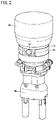
- the end effector exchange device 10 includes a first adapter 12 and a second adapter 34 having the same disk shape in plan view. As shown in FIG. 2 , the end effector exchange device 10 is used, for example, in a form in which the second adapter 34 to which a desired end effector 48 is attached is connected to the first adapter 12 attached to a robot arm 46.
- the first adapter 12 includes a diskshaped main body portion 14, and a slide portion 18 protruding downward from the main body portion 14.
- the slide portion 18 having a T-shaped cross section extends in a direction along the diameter of the main body portion 14.
- a guide rod 20 is disposed inside the slide portion 18.
- One end portion and the other end portion of the guide rod 20 are respectively disposed in a first guide groove 18a and a second guide groove 18b inside the slide portion 18.
- the guide rod 20 is supported so as to be movable in the longitudinal direction of the slide portion 18 (X direction).
- a cam member 22 is connected to the center of the guide rod 20 by first screws 26a.
- a release button 24 is connected to an end portion of the guide rod 20 by a second screw 26b.
- the first adapter 12 includes a concave surface 12a formed by cutting out a part of the outer periphery of the first adapter 12 in a direction orthogonal to the longitudinal direction of the slide portion 18. The release button 24 is exposed to the outside from the concave surface 12a.
- An end portion of the cam member 22 rises upward and constitutes a spring receiving portion 22c extending into the main body portion 14.
- a coil spring 28 is disposed between a spring receiver 30 arranged inside the main body portion 14 and the spring receiving portion 22c of the cam member 22.
- the cam member 22, the guide rod 20, and the release button 24, which are integrally connected to each other, receive the biasing force of the coil spring 28. As a result, the release button 24 is biased in a direction in which the release button 24 protrudes outward from the concave surface 12a.
- Both side surfaces of the cam member 22 are each provided with a cam portion 22a, and a ball receiving groove 22b positioned closer to the release button 24 than the cam portion 22a is.
- the cam portion 22a includes an inclined part 22a1 inclined at an angle ⁇ with respect to the moving direction of the guide rod 20 (X direction), and a parallel part 22a2 parallel to the moving direction of the guide rod 20.
- the parallel part 22a2 is positioned between the inclined part 22a1 and the ball receiving groove 22b (see FIG. 9 ).
- the slide portion 18 includes a pair of ball grooves 18c at positions adjacent to the cam member 22.
- a ball (steel ball) 32 is disposed in each ball groove 18c.
- the upper portion of the main body portion 14 includes a circular fitting portion 14a.
- a circular cover member 16 covering above the guide rod 20, the cam member 22, and the coil spring 28 is fitted to the fitting portion 14a.
- the fitting portion 14a serves as a positioning member when the first adapter 12 is attached to the robot arm 46.
- Reference symbol 14b denotes bolt insertion holes for attaching the first adapter 12 to the robot arm 46.
- the second adapter 34 includes an upper plate portion 36 having an opening 36a, and a lower plate portion 38 having a circular hole 38a.
- a U-shaped opening edge portion 36b of the upper plate portion 36 is connected to the lower plate portion 38 via a vertical wall portion 40.
- the opening edge portion 36b, the vertical wall portion 40, and the lower plate portion 38 constitute a T-shaped slot 42.
- the slide portion 18 of the first adapter 12 is fitted into the slot 42 of the second adapter 34, whereby the second adapter 34 is supported so as to be slidable in the horizontal direction with respect to the first adapter 12.
- an upper surface of the upper plate portion 36 of the second adapter 34 is parallel to a lower surface of the main body portion 14 of the first adapter 12.
- the upper surface and the lower surface face each other with a slight gap therebetween, or are in contact with each other.
- Reference symbol 34a denotes bolt insertion holes for attaching the end effector 48 to the second adapter 34.
- the central axis of the second adapter 34 coincides with the central axis of the first adapter 12, and the side surface of the second adapter 34 is flush with the side surface of the first adapter 12 (see FIG. 2 ).
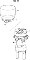
- the second adapter 34 separates from the first adapter 12 (see FIG. 13 ).
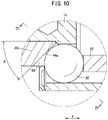
- the ball 32 disposed in the ball groove 18c of the slide portion 18 of the first adapter 12 is positioned between the cam member 22 disposed on the slide portion 18 and the opening edge portion 36b of the upper plate portion 36 of the second adapter 34.
- the opening edge portion 36b is provided with an engagement groove 44 having a wall surface against which the ball 32 can abut.
- a line (valley line 44a) connecting the deepest points of the engagement groove 44 is farther from the opening 36a as it goes downward.
- the valley line 44a is inclined by an angle ⁇ with respect to the upper surface of the upper plate portion 36 when viewed from the direction along the moving direction of the cam member 22.
- the valley line 44a of the engagement groove 44 is inclined by the angle ⁇ with respect to the advancing/retreating direction of the ball 32 (Y direction).
- FIG. 11 shows the outline of the engagement groove 44 when cut along a plane including the center of the ball 32 and perpendicular to the valley line 44a in a state where the ball 32 abuts against the wall surface of the engagement groove 44.
- This outline is a symmetrical combination of two arcs 44b and 44c having larger radii than the radius of the ball 32.
- the wall surface shape of the engagement groove 44 is formed by joining together two identical cylindrical surfaces each cut out with a central angle ⁇ smaller than 90 degrees, the two cylindrical surfaces being joined on their generating lines so that the joining line thereof becomes the valley line 44a of the engagement groove 44.
- the ball 32 abuts against the wall surface of the engagement groove 44 formed of the two cylindrical surfaces, at two points, namely, a point P1 and a point P2.
- the point denoted by reference symbol O1 is the center of a circle forming the arc 44b
- the point denoted by reference symbol O2 is the center of a circle forming the arc 44c.
- the cam member 22 receives the biasing force of the coil spring 28 and presses the ball 32 by the inclined part 22a1 thereof.
- the ball 32 protrudes from the ball groove 18c of the slide portion 18 and abuts against the wall surface of the engagement groove 44. Therefore, in the engagement groove 44, the second adapter 34 is engaged with the slide portion 18 of the first adapter 12 via the ball 32, and the second adapter 34 cannot be slid with respect to the first adapter 12.
- the ball 32 abuts against the wall surface of the engagement groove 44 that is inclined by the angle ⁇ with respect to the advancing/retreating direction of the ball 32. Therefore, a force that brings the upper surface of the second adapter 34 into close contact with the lower surface of the main body portion 14 of the first adapter 12 acts, and the second adapter 34 is supported by the first adapter 12 without rattling.
- the ball 32 abuts against the wall surface of the engagement groove 44 formed of the cylindrical surfaces, at two points, namely, the point P1 and the point P2.
- the surface pressure can be reduced, and rattling does not occur even when a large external force is applied to the second adapter 34.
- the inclined part 22a1 of the cam member 22 is connected to the ball receiving groove 22b via the parallel part 22a2. Therefore, even when an external force in a direction of sliding the second adapter 34 is applied to the second adapter in a state where the release button 24 is not pressed, the ball 32 stays in the parallel part 22a2 and does not move to the ball receiving groove 22b. Therefore, the second adapter 34 cannot be slid unless the release button 24 is operated.
- the guide rod 20 and the cam member 22 connected integrally with the release button 24 move against the biasing force of the coil spring 28. This allows the ball 32 to retreat from the engagement groove 44 toward the ball receiving groove 22b. Then, when the operator applies a force to the second adapter 34 in a direction in which the slide portion 18 of the first adapter 12 is pulled out from the slot 42 of the second adapter 34, the ball 32 drops into the ball receiving groove 22b and retreats to a position where the ball 32 does not protrude from the slide portion 18 (see FIG. 12 ). Therefore, the operator can separate the second adapter 34 from the first adapter 12 by sliding the second adapter 34 (see FIG. 13 ).
- the following procedure may be performed, for example.
- the operator fits the slide portion 18 of the first adapter 12 into the slot 42 of the second adapter 34 while supporting the second adapter 34 with both hands. Then, the operator slides the second adapter 34 relative to the first adapter 12 until the opening edge portion 36b at the entrance of the slot 42 abuts against the ball 32 protruding from the slide portion 18. In this state, since the slide portion 18 is fitted into the slot 42 over a predetermined length, the second adapter 34 does not fall even if the operator releases the hands from the second adapter 34.
- the operator slides the second adapter 34 with the other hand until the slide portion 18 of the first adapter 12 is inserted deep into the slot 42 of the second adapter 34. Then, when the operator takes the hand off the release button 24, the ball 32 abuts against the wall surface of the engagement groove 44 by the biasing force of the coil spring 28, and the end effector exchange device 10 returns to the initial state.
- the first adapter 12 and the second adapter 34 can be separated from each other by operating the release button 24 and also sliding the first adapter 12 and the second adapter 34 relative to each other. Therefore, the second adapter 34 to which the end effector 48 is attached is not unexpectedly detached and dropped, and the safety of the operator is improved.
- the description is made for a case in which the end effector exchange device 10 is used by attaching the first adapter 12 to the robot arm 46 and attaching the end effector 48 to the second adapter 34.
- the end effector exchange device 10 may be used by attaching the second adapter 34 to the robot arm 46 and attaching the end effector 48 to the first adapter 12.
- an end effector exchange device 50 according to a second embodiment of the present invention will be described with reference to FIGS. 14 to 16 .
- the second embodiment is different from the first embodiment in the shape of the engagement groove.
- the same components as those of the end effector exchange device 10 described above are denoted by the same reference numerals, and detailed description thereof will be omitted.
- the ball 32 disposed in the ball groove 18c of the slide portion 18 of the first adapter 12 is positioned between the cam member 22 supported by the slide portion 18 and the opening edge portion 36b of the upper plate portion 36 of the second adapter 34.
- the opening edge portion 36b includes an engagement groove 52 having a wall surface against which the ball 32 can abut.
- a valley line 52a of the engagement groove 52 is inclined by an angle ⁇ with respect to the advancing/retreating direction of the ball 32 (Y direction) so as to be farther from the opening 36a as it goes downward.
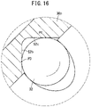
- FIG. 16 shows the outline of the engagement groove 52 when cut along a plane including the center of the ball 32 and perpendicular to the valley line 52a in a state where the ball 32 abuts against the wall surface of the engagement groove 52.
- the outline has a V-shape including two straight portions 52b and 52c.
- the wall surface shape of the engagement groove 52 is formed by causing two flat surfaces to intersect each other at an angle of approximately 90 degrees, and rounding the intersection portion thereof.
- the valley line 52a of the engagement groove 52 is a line passing through the deepest portion in the rounded part.
- the ball 32 abuts against the wall surface of the engagement groove 52 including the two flat surfaces, at two points, namely, a point P3 and a point P4.
- two flat surfaces constituting the wall surface shape of the engagement groove 52 intersect at an angle of approximately 90 degrees, but the two flat surfaces may intersect at an angle greater than 90 degrees or may intersect at an angle less than 90 degrees.
- the cam member 22 When the release button 24 is not operated, the cam member 22 receives the biasing force of the coil spring 28 and presses the ball 32 by the inclined part 22a1 thereof, and the ball 32 abuts against the wall surface of the engagement groove 52. Therefore, the engagement groove 52 of the second adapter 34 engages with the slide portion 18 of the first adapter 12 via the ball 32, and the second adapter 34 cannot be slid with respect to the first adapter 12.
- the cam member 22 moves against the biasing force of the coil spring 28, and the ball 32 can retreat from the engagement groove 52 toward the ball receiving groove 22b. Then, when the operator applies a force in a predetermined direction to the second adapter 34, the ball 32 retreats from the slide portion 18 to a position where the ball 32 does not protrude.
- the operator can separate the second adapter 34 from the first adapter 12 by sliding the second adapter 34. Therefore, the second adapter 34 to which the end effector 48 is attached is not unexpectedly detached and dropped, and the safety of the operator is improved.
- the ball 32 abuts against the wall surface of the engagement groove 52 that is inclined by the angle ⁇ with respect to the advancing/retreating direction of the ball 32. Therefore, a force that brings the upper surface of the second adapter 34 into close contact with the lower surface of the main body portion 14 of the first adapter 12 acts, and the second adapter 34 is supported by the first adapter 12 without rattling.
- the ball 32 abuts against the wall surface of the engagement groove 52 including two flat surfaces, at two points, namely, the point P3 and the point P4, rattling does not occur even when a large external force is applied to the second adapter 34.
- the wall surface shape of the engagement groove 52 is a combination of two flat surfaces, the processing of the engagement groove 52 is easy.
Landscapes
- Engineering & Computer Science (AREA)
- Robotics (AREA)
- Mechanical Engineering (AREA)
- Manipulator (AREA)
Abstract
Description
- The present invention relates to an end effector exchange device for manually exchanging members (hereinafter referred to as "end effectors") such as tools, jigs, chucks, and grippers attached to a robot arm, a transport device, or the like (hereinafter referred to as "robot arm or the like").
- Conventionally, there has been known a technique of detachably attaching end effectors to a tip of a robot arm so that various end effectors can be attached to the tip of the robot arm in accordance with work performed by an industrial robot.
- For example,
WO 2019/114895 A1 describes a connector in which a first portion connected to a robot and a second portion connected to a gripper are connected by a separable hinge, and a push button for releasing engagement between the first portion and the second portion is provided. - In such a device for exchanging an end effector, when the end effector is manually removed from a robot arm or the like, the end effector may be unexpectedly detached. In particular, when the weight of the end effector is large, it is necessary to consider the safety of an operator.
- The present invention has the object of solving the aforementioned problem.
- An end effector exchange device according to the present invention comprises: a first adapter; and a second adapter, one of the first adapter or the second adapter being attached to a robot arm or a transport device, and an end effector being attached to another one of the first adapter or the second adapter. A slide portion of the first adapter is fitted into a slot of the second adapter. A ball is disposed between a cam member supported by the slide portion and an opening edge portion constituting the slot. The ball is configured to advance toward or retreat from an engagement groove of the opening edge portion by movement of the cam member. By operating a release button connected integrally with the cam member and also sliding the first adapter and the second adapter relative to each other, the ball retreats, and the first adapter and the second adapter are separated from each other.
- According to the above-described end effector exchange device, the first adapter and the second adapter can be separated from each other by sliding the first adapter and the second adapter relative to each other after operating the release button. The first adapter and the second adapter cannot be separated from each other only by pressing the release button. Therefore, the adapter to which the end effector is attached is not unexpectedly detached, and the safety of the operator is improved.
- The end effector exchange device according to the present invention is configured such that the first adapter and the second adapter can be separated from each other by operating the release button and also sliding the first adapter and the second adapter relative to each other. Therefore, the adapter to which the end effector is attached is not unexpectedly detached, and the safety of the operator is improved.
- The above and other objects, features, and advantages of the present invention will become more apparent from the following description when taken in conjunction with the accompanying drawings, in which a preferred embodiment of the present invention is shown by way of illustrative example.
-
-
FIG. 1 is an external view of an end effector exchange device according to a first embodiment of the present invention; -
FIG. 2 is a view showing an example of use of the end effector exchange device ofFIG. 1 ; -
FIG. 3 is an external view of a first adapter of the end effector exchange device ofFIG. 1 ; -
FIG. 4 is an external view of a second adapter of the end effector exchange device ofFIG. 1 ; -
FIG. 5 is a plan view of the end effector exchange device ofFIG. 1 ; -
FIG. 6 is a cross-sectional view taken along line I-I ofFIG. 5 ; -
FIG. 7 is a cross-sectional view taken along line II-II ofFIG. 5 ; -
FIG. 8 is a cross-sectional view taken along line III-III ofFIG. 7 ; -
FIG. 9 is an enlarged view of a portion A ofFIG. 8 ; -
FIG. 10 is an enlarged view of a portion B ofFIG. 7 ; -
FIG. 11 is a cross-sectional view taken along line IV-IV ofFIG. 10 ; -
FIG. 12 is a view corresponding toFIG. 8 when a release button is operated; -
FIG. 13 is a view showing a state in which the second adapter is separated from the first adapter in the example of use ofFIG. 2 ; -
FIG. 14 is a view corresponding toFIG. 8 for describing an end effector exchange device according to a second embodiment of the present invention; -
FIG. 15 is a view corresponding toFIG. 10 for describing an engagement groove of the end effector exchange device ofFIG. 14 ; and -
FIG. 16 is a cross-sectional view taken along line V-V ofFIG. 15 . - In the following description, when terms in relation to upper and lower directions are used, for the sake of convenience, such terms refer to the directions shown in the drawings, however, the actual arrangement of the respective constituent members or the like is not limited thereby.
- An end
effector exchange device 10 according to a first embodiment of the present invention will be described with reference toFIGS. 1 to 13 . As shown inFIG. 1 , the endeffector exchange device 10 includes afirst adapter 12 and asecond adapter 34 having the same disk shape in plan view. As shown inFIG. 2 , the endeffector exchange device 10 is used, for example, in a form in which thesecond adapter 34 to which a desiredend effector 48 is attached is connected to thefirst adapter 12 attached to arobot arm 46. - As shown in
FIG. 3 , thefirst adapter 12 includes a diskshapedmain body portion 14, and aslide portion 18 protruding downward from themain body portion 14. Theslide portion 18 having a T-shaped cross section extends in a direction along the diameter of themain body portion 14. As shown inFIGS. 6 and8 , aguide rod 20 is disposed inside theslide portion 18. One end portion and the other end portion of theguide rod 20 are respectively disposed in afirst guide groove 18a and asecond guide groove 18b inside theslide portion 18. Thus, theguide rod 20 is supported so as to be movable in the longitudinal direction of the slide portion 18 (X direction). - A
cam member 22 is connected to the center of theguide rod 20 byfirst screws 26a. Arelease button 24 is connected to an end portion of theguide rod 20 by asecond screw 26b. Thefirst adapter 12 includes aconcave surface 12a formed by cutting out a part of the outer periphery of thefirst adapter 12 in a direction orthogonal to the longitudinal direction of theslide portion 18. Therelease button 24 is exposed to the outside from theconcave surface 12a. - An end portion of the
cam member 22 rises upward and constitutes aspring receiving portion 22c extending into themain body portion 14. Acoil spring 28 is disposed between aspring receiver 30 arranged inside themain body portion 14 and thespring receiving portion 22c of thecam member 22. Thecam member 22, theguide rod 20, and therelease button 24, which are integrally connected to each other, receive the biasing force of thecoil spring 28. As a result, therelease button 24 is biased in a direction in which therelease button 24 protrudes outward from theconcave surface 12a. - Both side surfaces of the
cam member 22 are each provided with acam portion 22a, and aball receiving groove 22b positioned closer to therelease button 24 than thecam portion 22a is. Thecam portion 22a includes an inclined part 22a1 inclined at an angle α with respect to the moving direction of the guide rod 20 (X direction), and a parallel part 22a2 parallel to the moving direction of theguide rod 20. The parallel part 22a2 is positioned between the inclined part 22a1 and theball receiving groove 22b (seeFIG. 9 ). Theslide portion 18 includes a pair ofball grooves 18c at positions adjacent to thecam member 22. A ball (steel ball) 32 is disposed in eachball groove 18c. - The upper portion of the
main body portion 14 includes acircular fitting portion 14a. Acircular cover member 16 covering above theguide rod 20, thecam member 22, and thecoil spring 28 is fitted to thefitting portion 14a. Thefitting portion 14a serves as a positioning member when thefirst adapter 12 is attached to therobot arm 46.Reference symbol 14b denotes bolt insertion holes for attaching thefirst adapter 12 to therobot arm 46. - As shown in
FIG. 4 , thesecond adapter 34 includes anupper plate portion 36 having anopening 36a, and alower plate portion 38 having acircular hole 38a. A U-shapedopening edge portion 36b of theupper plate portion 36 is connected to thelower plate portion 38 via avertical wall portion 40. The openingedge portion 36b, thevertical wall portion 40, and thelower plate portion 38 constitute a T-shapedslot 42. - The
slide portion 18 of thefirst adapter 12 is fitted into theslot 42 of thesecond adapter 34, whereby thesecond adapter 34 is supported so as to be slidable in the horizontal direction with respect to thefirst adapter 12. At this time, an upper surface of theupper plate portion 36 of thesecond adapter 34 is parallel to a lower surface of themain body portion 14 of thefirst adapter 12. The upper surface and the lower surface face each other with a slight gap therebetween, or are in contact with each other.Reference symbol 34a denotes bolt insertion holes for attaching theend effector 48 to thesecond adapter 34. - When the
slide portion 18 of thefirst adapter 12 is inserted deep into theslot 42 of thesecond adapter 34, the central axis of thesecond adapter 34 coincides with the central axis of thefirst adapter 12, and the side surface of thesecond adapter 34 is flush with the side surface of the first adapter 12 (seeFIG. 2 ). When theslide portion 18 is completely disengaged from theslot 42, thesecond adapter 34 separates from the first adapter 12 (seeFIG. 13 ). - As shown in
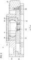
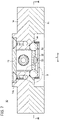
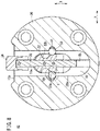
FIG. 8 , theball 32 disposed in theball groove 18c of theslide portion 18 of thefirst adapter 12 is positioned between thecam member 22 disposed on theslide portion 18 and theopening edge portion 36b of theupper plate portion 36 of thesecond adapter 34. The openingedge portion 36b is provided with anengagement groove 44 having a wall surface against which theball 32 can abut. When theslide portion 18 of thefirst adapter 12 is inserted deep into theslot 42 of thesecond adapter 34, theball 32 faces theengagement groove 44. - As shown in
FIGS. 7 and10 , a line (valley line 44a) connecting the deepest points of theengagement groove 44 is farther from theopening 36a as it goes downward. Thevalley line 44a is inclined by an angle β with respect to the upper surface of theupper plate portion 36 when viewed from the direction along the moving direction of thecam member 22. In other words, thevalley line 44a of theengagement groove 44 is inclined by the angle β with respect to the advancing/retreating direction of the ball 32 (Y direction). -
FIG. 11 shows the outline of theengagement groove 44 when cut along a plane including the center of theball 32 and perpendicular to thevalley line 44a in a state where theball 32 abuts against the wall surface of theengagement groove 44. This outline is a symmetrical combination of twoarcs ball 32. - Specifically, the wall surface shape of the
engagement groove 44 is formed by joining together two identical cylindrical surfaces each cut out with a central angle θ smaller than 90 degrees, the two cylindrical surfaces being joined on their generating lines so that the joining line thereof becomes thevalley line 44a of theengagement groove 44. Theball 32 abuts against the wall surface of theengagement groove 44 formed of the two cylindrical surfaces, at two points, namely, a point P1 and a point P2. The point denoted by reference symbol O1 is the center of a circle forming thearc 44b, and the point denoted by reference symbol O2 is the center of a circle forming thearc 44c. - The end
effector exchange device 10 according to the present embodiment is configured as described above, and the operation thereof will be described below. A state, in which theslide portion 18 of thefirst adapter 12 is inserted deep into theslot 42 of thesecond adapter 34 and therelease button 24 protrudes from theconcave surface 12a of thefirst adapter 12, is defined as an initial state (seeFIG. 8 ). - In the initial state, the
cam member 22 receives the biasing force of thecoil spring 28 and presses theball 32 by the inclined part 22a1 thereof. Theball 32 protrudes from theball groove 18c of theslide portion 18 and abuts against the wall surface of theengagement groove 44. Therefore, in theengagement groove 44, thesecond adapter 34 is engaged with theslide portion 18 of thefirst adapter 12 via theball 32, and thesecond adapter 34 cannot be slid with respect to thefirst adapter 12. - In this case, the
ball 32 abuts against the wall surface of theengagement groove 44 that is inclined by the angle β with respect to the advancing/retreating direction of theball 32. Therefore, a force that brings the upper surface of thesecond adapter 34 into close contact with the lower surface of themain body portion 14 of thefirst adapter 12 acts, and thesecond adapter 34 is supported by thefirst adapter 12 without rattling. In addition, theball 32 abuts against the wall surface of theengagement groove 44 formed of the cylindrical surfaces, at two points, namely, the point P1 and the point P2. For this reason, compared to a case where theball 32 abuts against the wall surface of theengagement groove 44 formed of a flat surface, the surface pressure can be reduced, and rattling does not occur even when a large external force is applied to thesecond adapter 34. - Further, the inclined part 22a1 of the
cam member 22 is connected to theball receiving groove 22b via the parallel part 22a2. Therefore, even when an external force in a direction of sliding thesecond adapter 34 is applied to the second adapter in a state where therelease button 24 is not pressed, theball 32 stays in the parallel part 22a2 and does not move to theball receiving groove 22b. Therefore, thesecond adapter 34 cannot be slid unless therelease button 24 is operated. - When an operator presses the
release button 24, theguide rod 20 and thecam member 22 connected integrally with therelease button 24 move against the biasing force of thecoil spring 28. This allows theball 32 to retreat from theengagement groove 44 toward theball receiving groove 22b. Then, when the operator applies a force to thesecond adapter 34 in a direction in which theslide portion 18 of thefirst adapter 12 is pulled out from theslot 42 of thesecond adapter 34, theball 32 drops into theball receiving groove 22b and retreats to a position where theball 32 does not protrude from the slide portion 18 (seeFIG. 12 ). Therefore, the operator can separate thesecond adapter 34 from thefirst adapter 12 by sliding the second adapter 34 (seeFIG. 13 ). - In order to connect the
second adapter 34 to thefirst adapter 12 after exchanging theend effector 48 attached to the separatedsecond adapter 34 with another end effector, the following procedure may be performed, for example. - First, the operator fits the
slide portion 18 of thefirst adapter 12 into theslot 42 of thesecond adapter 34 while supporting thesecond adapter 34 with both hands. Then, the operator slides thesecond adapter 34 relative to thefirst adapter 12 until the openingedge portion 36b at the entrance of theslot 42 abuts against theball 32 protruding from theslide portion 18. In this state, since theslide portion 18 is fitted into theslot 42 over a predetermined length, thesecond adapter 34 does not fall even if the operator releases the hands from thesecond adapter 34. - Next, while pressing the
release button 24 with one hand, the operator slides thesecond adapter 34 with the other hand until theslide portion 18 of thefirst adapter 12 is inserted deep into theslot 42 of thesecond adapter 34. Then, when the operator takes the hand off therelease button 24, theball 32 abuts against the wall surface of theengagement groove 44 by the biasing force of thecoil spring 28, and the endeffector exchange device 10 returns to the initial state. - According to the end
effector exchange device 10 of the present embodiment, thefirst adapter 12 and thesecond adapter 34 can be separated from each other by operating therelease button 24 and also sliding thefirst adapter 12 and thesecond adapter 34 relative to each other. Therefore, thesecond adapter 34 to which theend effector 48 is attached is not unexpectedly detached and dropped, and the safety of the operator is improved. - In the present embodiment, the description is made for a case in which the end
effector exchange device 10 is used by attaching thefirst adapter 12 to therobot arm 46 and attaching theend effector 48 to thesecond adapter 34. However, the endeffector exchange device 10 may be used by attaching thesecond adapter 34 to therobot arm 46 and attaching theend effector 48 to thefirst adapter 12. - Next, an end
effector exchange device 50 according to a second embodiment of the present invention will be described with reference toFIGS. 14 to 16 . The second embodiment is different from the first embodiment in the shape of the engagement groove. The same components as those of the endeffector exchange device 10 described above are denoted by the same reference numerals, and detailed description thereof will be omitted. - As shown in
FIG. 14 , theball 32 disposed in theball groove 18c of theslide portion 18 of thefirst adapter 12 is positioned between thecam member 22 supported by theslide portion 18 and theopening edge portion 36b of theupper plate portion 36 of thesecond adapter 34. The openingedge portion 36b includes anengagement groove 52 having a wall surface against which theball 32 can abut. As shown inFIG. 15 , avalley line 52a of theengagement groove 52 is inclined by an angle β with respect to the advancing/retreating direction of the ball 32 (Y direction) so as to be farther from theopening 36a as it goes downward. -
FIG. 16 shows the outline of theengagement groove 52 when cut along a plane including the center of theball 32 and perpendicular to thevalley line 52a in a state where theball 32 abuts against the wall surface of theengagement groove 52. The outline has a V-shape including twostraight portions engagement groove 52 is formed by causing two flat surfaces to intersect each other at an angle of approximately 90 degrees, and rounding the intersection portion thereof. Thevalley line 52a of theengagement groove 52 is a line passing through the deepest portion in the rounded part. Theball 32 abuts against the wall surface of theengagement groove 52 including the two flat surfaces, at two points, namely, a point P3 and a point P4. In the present embodiment, two flat surfaces constituting the wall surface shape of theengagement groove 52 intersect at an angle of approximately 90 degrees, but the two flat surfaces may intersect at an angle greater than 90 degrees or may intersect at an angle less than 90 degrees. - When the
release button 24 is not operated, thecam member 22 receives the biasing force of thecoil spring 28 and presses theball 32 by the inclined part 22a1 thereof, and theball 32 abuts against the wall surface of theengagement groove 52. Therefore, theengagement groove 52 of thesecond adapter 34 engages with theslide portion 18 of thefirst adapter 12 via theball 32, and thesecond adapter 34 cannot be slid with respect to thefirst adapter 12. - On the other hand, when the operator presses the
release button 24, thecam member 22 moves against the biasing force of thecoil spring 28, and theball 32 can retreat from theengagement groove 52 toward theball receiving groove 22b. Then, when the operator applies a force in a predetermined direction to thesecond adapter 34, theball 32 retreats from theslide portion 18 to a position where theball 32 does not protrude. The operator can separate thesecond adapter 34 from thefirst adapter 12 by sliding thesecond adapter 34. Therefore, thesecond adapter 34 to which theend effector 48 is attached is not unexpectedly detached and dropped, and the safety of the operator is improved. - The
ball 32 abuts against the wall surface of theengagement groove 52 that is inclined by the angle β with respect to the advancing/retreating direction of theball 32. Therefore, a force that brings the upper surface of thesecond adapter 34 into close contact with the lower surface of themain body portion 14 of thefirst adapter 12 acts, and thesecond adapter 34 is supported by thefirst adapter 12 without rattling. In addition, since theball 32 abuts against the wall surface of theengagement groove 52 including two flat surfaces, at two points, namely, the point P3 and the point P4, rattling does not occur even when a large external force is applied to thesecond adapter 34. Further, since the wall surface shape of theengagement groove 52 is a combination of two flat surfaces, the processing of theengagement groove 52 is easy.
Claims (7)
- An end effector exchange device (10, 50) comprising:a first adapter (12); anda second adapter (34),one of the first adapter or the second adapter being attached to a robot arm (46) or a transport device, and an end effector (48) being attached to another one of the first adapter or the second adapter, whereina slide portion (18) of the first adapter is fitted into a slot (42) of the second adapter,a ball (32) is disposed between a cam member (22) supported by the slide portion and an opening edge portion (36b) constituting the slot,the ball is configured to advance toward or retreat from an engagement groove (44, 52) of the opening edge portion by movement of the cam member, andby operating a release button (24) connected integrally with the cam member and also sliding the first adapter and the second adapter relative to each other, the ball retreats, and the first adapter and the second adapter are separated from each other.
- The end effector exchange device according to claim 1, wherein
the slide portion having a T-shaped cross section is fitted into the slot having a T shape. - The end effector exchange device according to claim 1, wherein
the cam member is connected to a guide rod (20) supported movably in a longitudinal direction of the slide portion. - The end effector exchange device according to claim 3, whereinthe cam member includes a cam portion (22a) and a ball receiving groove (22b),the cam portion is formed of an inclined part (22a1) inclined with respect to a moving direction of the guide rod, and a parallel part (22a2) parallel to the moving direction of the guide rod, andthe parallel part is positioned between the inclined part and the ball receiving groove.
- The end effector exchange device according to claim 1, wherein
a shape of a wall surface of the engagement groove is formed by joining together two cylindrical surfaces each cut out with a predetermined central angle, the two cylindrical surfaces being joined on generating lines thereof so that a joint line on which the generating lines are joined becomes a valley line of the engagement groove. - The end effector exchange device according to claim 1, wherein
a shape of a wall surface of the engagement groove is formed by causing two flat surfaces to intersect each other and rounding an intersection portion of the two flat surfaces. - The end effector exchange device according to claim 5 or 6, wherein
the valley line of the engagement groove is inclined with respect to an advancing or retreating direction of the ball.
Applications Claiming Priority (1)
| Application Number | Priority Date | Filing Date | Title |
|---|---|---|---|
| JP2021072709A JP7608959B2 (en) | 2021-04-22 | 2021-04-22 | End effector exchange device |
Publications (2)
| Publication Number | Publication Date |
|---|---|
| EP4082727A1 true EP4082727A1 (en) | 2022-11-02 |
| EP4082727B1 EP4082727B1 (en) | 2024-01-24 |
Family
ID=81308047
Family Applications (1)
| Application Number | Title | Priority Date | Filing Date |
|---|---|---|---|
| EP22168070.5A Active EP4082727B1 (en) | 2021-04-22 | 2022-04-13 | End effector exchange device |
Country Status (5)
| Country | Link |
|---|---|
| US (1) | US11679513B2 (en) |
| EP (1) | EP4082727B1 (en) |
| JP (1) | JP7608959B2 (en) |
| KR (1) | KR20220145774A (en) |
| CN (1) | CN115229822B (en) |
Families Citing this family (3)
| Publication number | Priority date | Publication date | Assignee | Title |
|---|---|---|---|---|
| US12043456B2 (en) * | 2021-08-17 | 2024-07-23 | United Parcel Service Of America, Inc. | Latching mechanisms, storage receptacles with latching mechanisms, and methods of manufacturing and using the same |
| US12234849B2 (en) * | 2021-10-08 | 2025-02-25 | Hanwit Precision Industries Ltd. | Pressable locating device and driving mechanism |
| CN116277125B (en) * | 2023-02-14 | 2026-01-02 | 上海微创医疗机器人(集团)股份有限公司 | Inter-segment connection device for robotic arms and surgical robotic arms and surgical robots incorporating it. |
Citations (6)
| Publication number | Priority date | Publication date | Assignee | Title |
|---|---|---|---|---|
| US20070235949A1 (en) * | 2006-03-14 | 2007-10-11 | Ati Industrial Automation | Robotic tool changer |
| US10047908B1 (en) * | 2017-06-20 | 2018-08-14 | Ati Industrial Automation, Inc. | Deformable pin locking mechanism for robotic tool changer |
| US20180257221A1 (en) * | 2015-08-24 | 2018-09-13 | Calvin Toothaker | Quick-release mechanism for tool adapter plate and robots incorporating the same |
| US10105855B2 (en) * | 2015-02-16 | 2018-10-23 | Norgren Automation Solutions, Llc | Quick disconnect apparatus for modular tooling |
| US10166685B2 (en) * | 2015-02-27 | 2019-01-01 | Kosmek Ltd. | Output device and output system |
| WO2019114895A1 (en) | 2017-12-14 | 2019-06-20 | Onrobot A/S | Easy collaborative tool changer |
Family Cites Families (27)
| Publication number | Priority date | Publication date | Assignee | Title |
|---|---|---|---|---|
| SU872184A1 (en) * | 1979-11-26 | 1981-10-15 | Производственное Объединение "Станкостроительный Завод" Им.Серго Орджоникидзе | Device for automatic change of tools |
| JP3381502B2 (en) * | 1996-02-13 | 2003-03-04 | 日産自動車株式会社 | Gun arm replacement structure and method for spot welding gun |
| JPH09272091A (en) * | 1996-04-09 | 1997-10-21 | Olympus Optical Co Ltd | Robot hand automatic changer |
| JP4131764B2 (en) * | 1998-09-01 | 2008-08-13 | 東芝エレベータ株式会社 | Elevator equipment |
| JP2002200585A (en) * | 2000-12-28 | 2002-07-16 | Fuji Mach Mfg Co Ltd | Device for holding electrical component |
| JP2009136942A (en) * | 2007-12-04 | 2009-06-25 | B L Auto Tec Kk | Fall prevention device of robot arm coupling device |
| KR101114626B1 (en) * | 2008-04-08 | 2012-03-14 | 가부시키가이샤 고베 세이코쇼 | Tool replacing device |
| JP5378758B2 (en) * | 2008-10-29 | 2013-12-25 | 株式会社ナベヤ | Fastening device |
| JP5369638B2 (en) * | 2008-11-21 | 2013-12-18 | 株式会社Ihi | Robot equipment |
| US10661449B2 (en) * | 2014-08-20 | 2020-05-26 | Ati Industrial Automation, Inc. | Safe robotic tool changer |
| JP6405190B2 (en) * | 2014-10-10 | 2018-10-17 | 株式会社コスメック | Output device |
| US9981391B2 (en) * | 2015-02-16 | 2018-05-29 | Norgren Automation Solutions, Llc | Quick disconnect apparatus for modular tooling |
| ITUB20155846A1 (en) * | 2015-11-24 | 2017-05-24 | Gimatic S R L | TOOL CHANGE DEVICE |
| JP6918535B2 (en) * | 2017-03-22 | 2021-08-11 | キヤノン株式会社 | Robot devices, replacement tools, robot arms, manufacturing methods for articles using robot devices, control methods for robot devices, control programs and recording media |
| KR102339489B1 (en) * | 2017-04-07 | 2021-12-17 | 리씽크 로보틱스 게엠베하 | Quick release mechanism for tool adapter plate and robot comprising same |
| US10335957B2 (en) * | 2017-04-25 | 2019-07-02 | Ati Industrial Automation, Inc. | Magnetically activated tool changer |
| US20190255713A1 (en) * | 2018-02-22 | 2019-08-22 | Delkor Systems, Inc. | Robotic End-of-Arm Manual Tool Changer |
| DE102019203475A1 (en) * | 2018-03-22 | 2019-09-26 | GIMATIC S.r.l. | Dovetail tool changer for industrial manipulators |
| CN109015760B (en) * | 2018-09-29 | 2023-08-29 | 华侨大学 | Quick change device for mechanical arm |
| US11565403B2 (en) * | 2018-10-09 | 2023-01-31 | Canon Kabushiki Kaisha | Attaching mechanism, robot apparatus, and attaching method |
| JP7127836B2 (en) * | 2019-02-13 | 2022-08-30 | 株式会社コスメック | tool changer |
| DE102019125915A1 (en) * | 2019-09-26 | 2021-04-01 | J. Schmalz Gmbh | Handling system |
| US20210114233A1 (en) * | 2019-10-18 | 2021-04-22 | Delaware Capital Formation, Inc. | Manual Tool Changer With Pneumatic And Electric Utilities |
| CN212601904U (en) * | 2020-06-09 | 2021-02-26 | 上海东普信息科技有限公司 | Mechanical arm clamp connecting device |
| US11850733B2 (en) * | 2020-06-11 | 2023-12-26 | Ati Industrial Automation, Inc. | Robotic tool changer coupling mechanism with increased torsional rigidity and reduced freeplay |
| CN111775173A (en) * | 2020-07-13 | 2020-10-16 | 上海快点机器人科技有限公司 | Locking mechanism |
| US20220297314A1 (en) * | 2021-03-16 | 2022-09-22 | Mark Eugene Ganninger | Mechanical Robot Tool Changer |
-
2021
- 2021-04-22 JP JP2021072709A patent/JP7608959B2/en active Active
-
2022
- 2022-04-12 US US17/658,889 patent/US11679513B2/en active Active
- 2022-04-13 EP EP22168070.5A patent/EP4082727B1/en active Active
- 2022-04-19 KR KR1020220048093A patent/KR20220145774A/en active Pending
- 2022-04-21 CN CN202210423818.9A patent/CN115229822B/en active Active
Patent Citations (6)
| Publication number | Priority date | Publication date | Assignee | Title |
|---|---|---|---|---|
| US20070235949A1 (en) * | 2006-03-14 | 2007-10-11 | Ati Industrial Automation | Robotic tool changer |
| US10105855B2 (en) * | 2015-02-16 | 2018-10-23 | Norgren Automation Solutions, Llc | Quick disconnect apparatus for modular tooling |
| US10166685B2 (en) * | 2015-02-27 | 2019-01-01 | Kosmek Ltd. | Output device and output system |
| US20180257221A1 (en) * | 2015-08-24 | 2018-09-13 | Calvin Toothaker | Quick-release mechanism for tool adapter plate and robots incorporating the same |
| US10047908B1 (en) * | 2017-06-20 | 2018-08-14 | Ati Industrial Automation, Inc. | Deformable pin locking mechanism for robotic tool changer |
| WO2019114895A1 (en) | 2017-12-14 | 2019-06-20 | Onrobot A/S | Easy collaborative tool changer |
Also Published As
| Publication number | Publication date |
|---|---|
| CN115229822A (en) | 2022-10-25 |
| JP2022167131A (en) | 2022-11-04 |
| US20220339797A1 (en) | 2022-10-27 |
| JP7608959B2 (en) | 2025-01-07 |
| EP4082727B1 (en) | 2024-01-24 |
| TW202247967A (en) | 2022-12-16 |
| US11679513B2 (en) | 2023-06-20 |
| KR20220145774A (en) | 2022-10-31 |
| CN115229822B (en) | 2026-03-27 |
Similar Documents
| Publication | Publication Date | Title |
|---|---|---|
| EP4082727B1 (en) | End effector exchange device | |
| US11370104B2 (en) | Connection structure of operation rod | |
| EP4190515A1 (en) | Robotic tool changer system and method for performing tool change with robotic tool changer system | |
| US20130313791A1 (en) | Robotic tool change system | |
| US20220134582A1 (en) | Robotic processing system | |
| US20220234218A1 (en) | Tool changer for a robot and changing system therefor | |
| US10814444B2 (en) | Workpiece clamping device clamping and securing workpiece | |
| US12472645B2 (en) | Robotic tool changer system through magnetic coupling force and all-round mechanical locking | |
| US10910765B2 (en) | Lever-type connector | |
| US20200316692A1 (en) | Chuck device | |
| EP3625001B1 (en) | Workpiece gripping device | |
| EP3625002B1 (en) | Workpiece gripping device | |
| US20220193925A1 (en) | Tool Changing System, Industrial Robot And Method Of Handling Tool By Industrial Robot | |
| EP4000800A1 (en) | Lockable tool clamp | |
| EP4228838A1 (en) | Tool coupling | |
| US10835965B2 (en) | Chuck mechanism | |
| JP4475392B2 (en) | Work holder | |
| JP3222824U (en) | E-type retaining ring installation tool | |
| EP3764193B1 (en) | Handle device and punching machine | |
| KR20250138272A (en) | Coating removal device and blade manufacturing method | |
| JP7130938B2 (en) | Chuck |
Legal Events
| Date | Code | Title | Description |
|---|---|---|---|
| PUAI | Public reference made under article 153(3) epc to a published international application that has entered the european phase |
Free format text: ORIGINAL CODE: 0009012 |
|
| STAA | Information on the status of an ep patent application or granted ep patent |
Free format text: STATUS: THE APPLICATION HAS BEEN PUBLISHED |
|
| AK | Designated contracting states |
Kind code of ref document: A1 Designated state(s): AL AT BE BG CH CY CZ DE DK EE ES FI FR GB GR HR HU IE IS IT LI LT LU LV MC MK MT NL NO PL PT RO RS SE SI SK SM TR |
|
| STAA | Information on the status of an ep patent application or granted ep patent |
Free format text: STATUS: REQUEST FOR EXAMINATION WAS MADE |
|
| 17P | Request for examination filed |
Effective date: 20221227 |
|
| RBV | Designated contracting states (corrected) |
Designated state(s): AL AT BE BG CH CY CZ DE DK EE ES FI FR GB GR HR HU IE IS IT LI LT LU LV MC MK MT NL NO PL PT RO RS SE SI SK SM TR |
|
| GRAP | Despatch of communication of intention to grant a patent |
Free format text: ORIGINAL CODE: EPIDOSNIGR1 |
|
| STAA | Information on the status of an ep patent application or granted ep patent |
Free format text: STATUS: GRANT OF PATENT IS INTENDED |
|
| RIC1 | Information provided on ipc code assigned before grant |
Ipc: B25J 15/04 20060101AFI20230420BHEP |
|
| INTG | Intention to grant announced |
Effective date: 20230512 |
|
| GRAJ | Information related to disapproval of communication of intention to grant by the applicant or resumption of examination proceedings by the epo deleted |
Free format text: ORIGINAL CODE: EPIDOSDIGR1 |
|
| STAA | Information on the status of an ep patent application or granted ep patent |
Free format text: STATUS: REQUEST FOR EXAMINATION WAS MADE |
|
| INTC | Intention to grant announced (deleted) | ||
| GRAS | Grant fee paid |
Free format text: ORIGINAL CODE: EPIDOSNIGR3 |
|
| STAA | Information on the status of an ep patent application or granted ep patent |
Free format text: STATUS: GRANT OF PATENT IS INTENDED |
|
| GRAP | Despatch of communication of intention to grant a patent |
Free format text: ORIGINAL CODE: EPIDOSNIGR1 |
|
| INTG | Intention to grant announced |
Effective date: 20231031 |
|
| GRAA | (expected) grant |
Free format text: ORIGINAL CODE: 0009210 |
|
| STAA | Information on the status of an ep patent application or granted ep patent |
Free format text: STATUS: THE PATENT HAS BEEN GRANTED |
|
| AK | Designated contracting states |
Kind code of ref document: B1 Designated state(s): AL AT BE BG CH CY CZ DE DK EE ES FI FR GB GR HR HU IE IS IT LI LT LU LV MC MK MT NL NO PL PT RO RS SE SI SK SM TR |
|
| REG | Reference to a national code |
Ref country code: GB Ref legal event code: FG4D |
|
| REG | Reference to a national code |
Ref country code: CH Ref legal event code: EP |
|
| REG | Reference to a national code |
Ref country code: DE Ref legal event code: R096 Ref document number: 602022001657 Country of ref document: DE |
|
| REG | Reference to a national code |
Ref country code: IE Ref legal event code: FG4D |
|
| REG | Reference to a national code |
Ref country code: LT Ref legal event code: MG9D |
|
| REG | Reference to a national code |
Ref country code: NL Ref legal event code: MP Effective date: 20240124 |
|
| PG25 | Lapsed in a contracting state [announced via postgrant information from national office to epo] |
Ref country code: NL Free format text: LAPSE BECAUSE OF FAILURE TO SUBMIT A TRANSLATION OF THE DESCRIPTION OR TO PAY THE FEE WITHIN THE PRESCRIBED TIME-LIMIT Effective date: 20240124 |
|
| PG25 | Lapsed in a contracting state [announced via postgrant information from national office to epo] |
Ref country code: NL Free format text: LAPSE BECAUSE OF FAILURE TO SUBMIT A TRANSLATION OF THE DESCRIPTION OR TO PAY THE FEE WITHIN THE PRESCRIBED TIME-LIMIT Effective date: 20240124 |
|
| PG25 | Lapsed in a contracting state [announced via postgrant information from national office to epo] |
Ref country code: IS Free format text: LAPSE BECAUSE OF FAILURE TO SUBMIT A TRANSLATION OF THE DESCRIPTION OR TO PAY THE FEE WITHIN THE PRESCRIBED TIME-LIMIT Effective date: 20240524 |
|
| PG25 | Lapsed in a contracting state [announced via postgrant information from national office to epo] |
Ref country code: LT Free format text: LAPSE BECAUSE OF FAILURE TO SUBMIT A TRANSLATION OF THE DESCRIPTION OR TO PAY THE FEE WITHIN THE PRESCRIBED TIME-LIMIT Effective date: 20240124 |
|
| PG25 | Lapsed in a contracting state [announced via postgrant information from national office to epo] |
Ref country code: GR Free format text: LAPSE BECAUSE OF FAILURE TO SUBMIT A TRANSLATION OF THE DESCRIPTION OR TO PAY THE FEE WITHIN THE PRESCRIBED TIME-LIMIT Effective date: 20240425 |
|
| REG | Reference to a national code |
Ref country code: AT Ref legal event code: MK05 Ref document number: 1651827 Country of ref document: AT Kind code of ref document: T Effective date: 20240124 |
|
| PG25 | Lapsed in a contracting state [announced via postgrant information from national office to epo] |
Ref country code: RS Free format text: LAPSE BECAUSE OF FAILURE TO SUBMIT A TRANSLATION OF THE DESCRIPTION OR TO PAY THE FEE WITHIN THE PRESCRIBED TIME-LIMIT Effective date: 20240424 Ref country code: HR Free format text: LAPSE BECAUSE OF FAILURE TO SUBMIT A TRANSLATION OF THE DESCRIPTION OR TO PAY THE FEE WITHIN THE PRESCRIBED TIME-LIMIT Effective date: 20240124 |
|
| PG25 | Lapsed in a contracting state [announced via postgrant information from national office to epo] |
Ref country code: ES Free format text: LAPSE BECAUSE OF FAILURE TO SUBMIT A TRANSLATION OF THE DESCRIPTION OR TO PAY THE FEE WITHIN THE PRESCRIBED TIME-LIMIT Effective date: 20240124 |
|
| PG25 | Lapsed in a contracting state [announced via postgrant information from national office to epo] |
Ref country code: AT Free format text: LAPSE BECAUSE OF FAILURE TO SUBMIT A TRANSLATION OF THE DESCRIPTION OR TO PAY THE FEE WITHIN THE PRESCRIBED TIME-LIMIT Effective date: 20240124 |
|
| PG25 | Lapsed in a contracting state [announced via postgrant information from national office to epo] |
Ref country code: RS Free format text: LAPSE BECAUSE OF FAILURE TO SUBMIT A TRANSLATION OF THE DESCRIPTION OR TO PAY THE FEE WITHIN THE PRESCRIBED TIME-LIMIT Effective date: 20240424 Ref country code: NO Free format text: LAPSE BECAUSE OF FAILURE TO SUBMIT A TRANSLATION OF THE DESCRIPTION OR TO PAY THE FEE WITHIN THE PRESCRIBED TIME-LIMIT Effective date: 20240424 Ref country code: LT Free format text: LAPSE BECAUSE OF FAILURE TO SUBMIT A TRANSLATION OF THE DESCRIPTION OR TO PAY THE FEE WITHIN THE PRESCRIBED TIME-LIMIT Effective date: 20240124 Ref country code: IS Free format text: LAPSE BECAUSE OF FAILURE TO SUBMIT A TRANSLATION OF THE DESCRIPTION OR TO PAY THE FEE WITHIN THE PRESCRIBED TIME-LIMIT Effective date: 20240524 Ref country code: HR Free format text: LAPSE BECAUSE OF FAILURE TO SUBMIT A TRANSLATION OF THE DESCRIPTION OR TO PAY THE FEE WITHIN THE PRESCRIBED TIME-LIMIT Effective date: 20240124 Ref country code: GR Free format text: LAPSE BECAUSE OF FAILURE TO SUBMIT A TRANSLATION OF THE DESCRIPTION OR TO PAY THE FEE WITHIN THE PRESCRIBED TIME-LIMIT Effective date: 20240425 Ref country code: FI Free format text: LAPSE BECAUSE OF FAILURE TO SUBMIT A TRANSLATION OF THE DESCRIPTION OR TO PAY THE FEE WITHIN THE PRESCRIBED TIME-LIMIT Effective date: 20240124 Ref country code: ES Free format text: LAPSE BECAUSE OF FAILURE TO SUBMIT A TRANSLATION OF THE DESCRIPTION OR TO PAY THE FEE WITHIN THE PRESCRIBED TIME-LIMIT Effective date: 20240124 Ref country code: BG Free format text: LAPSE BECAUSE OF FAILURE TO SUBMIT A TRANSLATION OF THE DESCRIPTION OR TO PAY THE FEE WITHIN THE PRESCRIBED TIME-LIMIT Effective date: 20240124 Ref country code: AT Free format text: LAPSE BECAUSE OF FAILURE TO SUBMIT A TRANSLATION OF THE DESCRIPTION OR TO PAY THE FEE WITHIN THE PRESCRIBED TIME-LIMIT Effective date: 20240124 |
|
| PG25 | Lapsed in a contracting state [announced via postgrant information from national office to epo] |
Ref country code: PL Free format text: LAPSE BECAUSE OF FAILURE TO SUBMIT A TRANSLATION OF THE DESCRIPTION OR TO PAY THE FEE WITHIN THE PRESCRIBED TIME-LIMIT Effective date: 20240124 Ref country code: PT Free format text: LAPSE BECAUSE OF FAILURE TO SUBMIT A TRANSLATION OF THE DESCRIPTION OR TO PAY THE FEE WITHIN THE PRESCRIBED TIME-LIMIT Effective date: 20240524 |
|
| PG25 | Lapsed in a contracting state [announced via postgrant information from national office to epo] |
Ref country code: SE Free format text: LAPSE BECAUSE OF FAILURE TO SUBMIT A TRANSLATION OF THE DESCRIPTION OR TO PAY THE FEE WITHIN THE PRESCRIBED TIME-LIMIT Effective date: 20240124 Ref country code: PT Free format text: LAPSE BECAUSE OF FAILURE TO SUBMIT A TRANSLATION OF THE DESCRIPTION OR TO PAY THE FEE WITHIN THE PRESCRIBED TIME-LIMIT Effective date: 20240524 Ref country code: PL Free format text: LAPSE BECAUSE OF FAILURE TO SUBMIT A TRANSLATION OF THE DESCRIPTION OR TO PAY THE FEE WITHIN THE PRESCRIBED TIME-LIMIT Effective date: 20240124 Ref country code: LV Free format text: LAPSE BECAUSE OF FAILURE TO SUBMIT A TRANSLATION OF THE DESCRIPTION OR TO PAY THE FEE WITHIN THE PRESCRIBED TIME-LIMIT Effective date: 20240124 |
|
| PG25 | Lapsed in a contracting state [announced via postgrant information from national office to epo] |
Ref country code: DK Free format text: LAPSE BECAUSE OF FAILURE TO SUBMIT A TRANSLATION OF THE DESCRIPTION OR TO PAY THE FEE WITHIN THE PRESCRIBED TIME-LIMIT Effective date: 20240124 |
|
| PG25 | Lapsed in a contracting state [announced via postgrant information from national office to epo] |
Ref country code: SM Free format text: LAPSE BECAUSE OF FAILURE TO SUBMIT A TRANSLATION OF THE DESCRIPTION OR TO PAY THE FEE WITHIN THE PRESCRIBED TIME-LIMIT Effective date: 20240124 |
|
| PG25 | Lapsed in a contracting state [announced via postgrant information from national office to epo] |
Ref country code: EE Free format text: LAPSE BECAUSE OF FAILURE TO SUBMIT A TRANSLATION OF THE DESCRIPTION OR TO PAY THE FEE WITHIN THE PRESCRIBED TIME-LIMIT Effective date: 20240124 Ref country code: CZ Free format text: LAPSE BECAUSE OF FAILURE TO SUBMIT A TRANSLATION OF THE DESCRIPTION OR TO PAY THE FEE WITHIN THE PRESCRIBED TIME-LIMIT Effective date: 20240124 |
|
| REG | Reference to a national code |
Ref country code: DE Ref legal event code: R097 Ref document number: 602022001657 Country of ref document: DE |
|
| PG25 | Lapsed in a contracting state [announced via postgrant information from national office to epo] |
Ref country code: SK Free format text: LAPSE BECAUSE OF FAILURE TO SUBMIT A TRANSLATION OF THE DESCRIPTION OR TO PAY THE FEE WITHIN THE PRESCRIBED TIME-LIMIT Effective date: 20240124 |
|
| PG25 | Lapsed in a contracting state [announced via postgrant information from national office to epo] |
Ref country code: SM Free format text: LAPSE BECAUSE OF FAILURE TO SUBMIT A TRANSLATION OF THE DESCRIPTION OR TO PAY THE FEE WITHIN THE PRESCRIBED TIME-LIMIT Effective date: 20240124 Ref country code: SK Free format text: LAPSE BECAUSE OF FAILURE TO SUBMIT A TRANSLATION OF THE DESCRIPTION OR TO PAY THE FEE WITHIN THE PRESCRIBED TIME-LIMIT Effective date: 20240124 Ref country code: EE Free format text: LAPSE BECAUSE OF FAILURE TO SUBMIT A TRANSLATION OF THE DESCRIPTION OR TO PAY THE FEE WITHIN THE PRESCRIBED TIME-LIMIT Effective date: 20240124 Ref country code: DK Free format text: LAPSE BECAUSE OF FAILURE TO SUBMIT A TRANSLATION OF THE DESCRIPTION OR TO PAY THE FEE WITHIN THE PRESCRIBED TIME-LIMIT Effective date: 20240124 Ref country code: CZ Free format text: LAPSE BECAUSE OF FAILURE TO SUBMIT A TRANSLATION OF THE DESCRIPTION OR TO PAY THE FEE WITHIN THE PRESCRIBED TIME-LIMIT Effective date: 20240124 |
|
| PG25 | Lapsed in a contracting state [announced via postgrant information from national office to epo] |
Ref country code: MC Free format text: LAPSE BECAUSE OF FAILURE TO SUBMIT A TRANSLATION OF THE DESCRIPTION OR TO PAY THE FEE WITHIN THE PRESCRIBED TIME-LIMIT Effective date: 20240124 |
|
| PG25 | Lapsed in a contracting state [announced via postgrant information from national office to epo] |
Ref country code: MC Free format text: LAPSE BECAUSE OF FAILURE TO SUBMIT A TRANSLATION OF THE DESCRIPTION OR TO PAY THE FEE WITHIN THE PRESCRIBED TIME-LIMIT Effective date: 20240124 |
|
| PLBE | No opposition filed within time limit |
Free format text: ORIGINAL CODE: 0009261 |
|
| STAA | Information on the status of an ep patent application or granted ep patent |
Free format text: STATUS: NO OPPOSITION FILED WITHIN TIME LIMIT |
|
| PG25 | Lapsed in a contracting state [announced via postgrant information from national office to epo] |
Ref country code: IT Free format text: LAPSE BECAUSE OF FAILURE TO SUBMIT A TRANSLATION OF THE DESCRIPTION OR TO PAY THE FEE WITHIN THE PRESCRIBED TIME-LIMIT Effective date: 20240124 |
|
| PG25 | Lapsed in a contracting state [announced via postgrant information from national office to epo] |
Ref country code: LU Free format text: LAPSE BECAUSE OF NON-PAYMENT OF DUE FEES Effective date: 20240413 |
|
| REG | Reference to a national code |
Ref country code: BE Ref legal event code: MM Effective date: 20240430 |
|
| PG25 | Lapsed in a contracting state [announced via postgrant information from national office to epo] |
Ref country code: LU Free format text: LAPSE BECAUSE OF NON-PAYMENT OF DUE FEES Effective date: 20240413 Ref country code: IT Free format text: LAPSE BECAUSE OF FAILURE TO SUBMIT A TRANSLATION OF THE DESCRIPTION OR TO PAY THE FEE WITHIN THE PRESCRIBED TIME-LIMIT Effective date: 20240124 |
|
| 26N | No opposition filed |
Effective date: 20241025 |
|
| PG25 | Lapsed in a contracting state [announced via postgrant information from national office to epo] |
Ref country code: BE Free format text: LAPSE BECAUSE OF NON-PAYMENT OF DUE FEES Effective date: 20240430 |
|
| PG25 | Lapsed in a contracting state [announced via postgrant information from national office to epo] |
Ref country code: FR Free format text: LAPSE BECAUSE OF NON-PAYMENT OF DUE FEES Effective date: 20240430 |
|
| PG25 | Lapsed in a contracting state [announced via postgrant information from national office to epo] |
Ref country code: FR Free format text: LAPSE BECAUSE OF NON-PAYMENT OF DUE FEES Effective date: 20240430 Ref country code: BE Free format text: LAPSE BECAUSE OF NON-PAYMENT OF DUE FEES Effective date: 20240430 |
|
| PG25 | Lapsed in a contracting state [announced via postgrant information from national office to epo] |
Ref country code: IE Free format text: LAPSE BECAUSE OF NON-PAYMENT OF DUE FEES Effective date: 20240413 |
|
| PG25 | Lapsed in a contracting state [announced via postgrant information from national office to epo] |
Ref country code: SI Free format text: LAPSE BECAUSE OF FAILURE TO SUBMIT A TRANSLATION OF THE DESCRIPTION OR TO PAY THE FEE WITHIN THE PRESCRIBED TIME-LIMIT Effective date: 20240124 |
|
| PGFP | Annual fee paid to national office [announced via postgrant information from national office to epo] |
Ref country code: DE Payment date: 20250422 Year of fee payment: 4 |
|
| PG25 | Lapsed in a contracting state [announced via postgrant information from national office to epo] |
Ref country code: RO Free format text: LAPSE BECAUSE OF FAILURE TO SUBMIT A TRANSLATION OF THE DESCRIPTION OR TO PAY THE FEE WITHIN THE PRESCRIBED TIME-LIMIT Effective date: 20240124 |
|
| PG25 | Lapsed in a contracting state [announced via postgrant information from national office to epo] |
Ref country code: CY Free format text: LAPSE BECAUSE OF FAILURE TO SUBMIT A TRANSLATION OF THE DESCRIPTION OR TO PAY THE FEE WITHIN THE PRESCRIBED TIME-LIMIT; INVALID AB INITIO Effective date: 20220413 |
|
| PG25 | Lapsed in a contracting state [announced via postgrant information from national office to epo] |
Ref country code: HU Free format text: LAPSE BECAUSE OF FAILURE TO SUBMIT A TRANSLATION OF THE DESCRIPTION OR TO PAY THE FEE WITHIN THE PRESCRIBED TIME-LIMIT; INVALID AB INITIO Effective date: 20220413 |
|
| REG | Reference to a national code |
Ref country code: CH Ref legal event code: H13 Free format text: ST27 STATUS EVENT CODE: U-0-0-H10-H13 (AS PROVIDED BY THE NATIONAL OFFICE) Effective date: 20251125 |
|
| PG25 | Lapsed in a contracting state [announced via postgrant information from national office to epo] |
Ref country code: CH Free format text: LAPSE BECAUSE OF NON-PAYMENT OF DUE FEES Effective date: 20250430 |