EP4082667A1 - Electrostatic precipitator - Google Patents
Electrostatic precipitator Download PDFInfo
- Publication number
- EP4082667A1 EP4082667A1 EP21858106.4A EP21858106A EP4082667A1 EP 4082667 A1 EP4082667 A1 EP 4082667A1 EP 21858106 A EP21858106 A EP 21858106A EP 4082667 A1 EP4082667 A1 EP 4082667A1
- Authority
- EP
- European Patent Office
- Prior art keywords
- exhaust gas
- electrostatic precipitator
- temperature
- electrostatic
- charging
- Prior art date
- Legal status (The legal status is an assumption and is not a legal conclusion. Google has not performed a legal analysis and makes no representation as to the accuracy of the status listed.)
- Withdrawn
Links
Images





Classifications
-
- B—PERFORMING OPERATIONS; TRANSPORTING
- B03—SEPARATION OF SOLID MATERIALS USING LIQUIDS OR USING PNEUMATIC TABLES OR JIGS; MAGNETIC OR ELECTROSTATIC SEPARATION OF SOLID MATERIALS FROM SOLID MATERIALS OR FLUIDS; SEPARATION BY HIGH-VOLTAGE ELECTRIC FIELDS
- B03C—MAGNETIC OR ELECTROSTATIC SEPARATION OF SOLID MATERIALS FROM SOLID MATERIALS OR FLUIDS; SEPARATION BY HIGH-VOLTAGE ELECTRIC FIELDS
- B03C3/00—Separating dispersed particles from gases or vapour, e.g. air, by electrostatic effect
- B03C3/02—Plant or installations having external electricity supply
- B03C3/025—Combinations of electrostatic separators, e.g. in parallel or in series, stacked separators or dry-wet separator combinations
-
- B—PERFORMING OPERATIONS; TRANSPORTING
- B03—SEPARATION OF SOLID MATERIALS USING LIQUIDS OR USING PNEUMATIC TABLES OR JIGS; MAGNETIC OR ELECTROSTATIC SEPARATION OF SOLID MATERIALS FROM SOLID MATERIALS OR FLUIDS; SEPARATION BY HIGH-VOLTAGE ELECTRIC FIELDS
- B03C—MAGNETIC OR ELECTROSTATIC SEPARATION OF SOLID MATERIALS FROM SOLID MATERIALS OR FLUIDS; SEPARATION BY HIGH-VOLTAGE ELECTRIC FIELDS
- B03C3/00—Separating dispersed particles from gases or vapour, e.g. air, by electrostatic effect
- B03C3/34—Constructional details or accessories or operation thereof
- B03C3/40—Electrode constructions
- B03C3/41—Ionising-electrodes
-
- B—PERFORMING OPERATIONS; TRANSPORTING
- B03—SEPARATION OF SOLID MATERIALS USING LIQUIDS OR USING PNEUMATIC TABLES OR JIGS; MAGNETIC OR ELECTROSTATIC SEPARATION OF SOLID MATERIALS FROM SOLID MATERIALS OR FLUIDS; SEPARATION BY HIGH-VOLTAGE ELECTRIC FIELDS
- B03C—MAGNETIC OR ELECTROSTATIC SEPARATION OF SOLID MATERIALS FROM SOLID MATERIALS OR FLUIDS; SEPARATION BY HIGH-VOLTAGE ELECTRIC FIELDS
- B03C3/00—Separating dispersed particles from gases or vapour, e.g. air, by electrostatic effect
- B03C3/017—Combinations of electrostatic separation with other processes, not otherwise provided for
-
- B—PERFORMING OPERATIONS; TRANSPORTING
- B03—SEPARATION OF SOLID MATERIALS USING LIQUIDS OR USING PNEUMATIC TABLES OR JIGS; MAGNETIC OR ELECTROSTATIC SEPARATION OF SOLID MATERIALS FROM SOLID MATERIALS OR FLUIDS; SEPARATION BY HIGH-VOLTAGE ELECTRIC FIELDS
- B03C—MAGNETIC OR ELECTROSTATIC SEPARATION OF SOLID MATERIALS FROM SOLID MATERIALS OR FLUIDS; SEPARATION BY HIGH-VOLTAGE ELECTRIC FIELDS
- B03C3/00—Separating dispersed particles from gases or vapour, e.g. air, by electrostatic effect
- B03C3/02—Plant or installations having external electricity supply
- B03C3/04—Plant or installations having external electricity supply dry type
- B03C3/06—Plant or installations having external electricity supply dry type characterised by presence of stationary tube electrodes
-
- B—PERFORMING OPERATIONS; TRANSPORTING
- B03—SEPARATION OF SOLID MATERIALS USING LIQUIDS OR USING PNEUMATIC TABLES OR JIGS; MAGNETIC OR ELECTROSTATIC SEPARATION OF SOLID MATERIALS FROM SOLID MATERIALS OR FLUIDS; SEPARATION BY HIGH-VOLTAGE ELECTRIC FIELDS
- B03C—MAGNETIC OR ELECTROSTATIC SEPARATION OF SOLID MATERIALS FROM SOLID MATERIALS OR FLUIDS; SEPARATION BY HIGH-VOLTAGE ELECTRIC FIELDS
- B03C3/00—Separating dispersed particles from gases or vapour, e.g. air, by electrostatic effect
- B03C3/02—Plant or installations having external electricity supply
- B03C3/04—Plant or installations having external electricity supply dry type
- B03C3/08—Plant or installations having external electricity supply dry type characterised by presence of stationary flat electrodes arranged with their flat surfaces parallel to the gas stream
-
- B—PERFORMING OPERATIONS; TRANSPORTING
- B03—SEPARATION OF SOLID MATERIALS USING LIQUIDS OR USING PNEUMATIC TABLES OR JIGS; MAGNETIC OR ELECTROSTATIC SEPARATION OF SOLID MATERIALS FROM SOLID MATERIALS OR FLUIDS; SEPARATION BY HIGH-VOLTAGE ELECTRIC FIELDS
- B03C—MAGNETIC OR ELECTROSTATIC SEPARATION OF SOLID MATERIALS FROM SOLID MATERIALS OR FLUIDS; SEPARATION BY HIGH-VOLTAGE ELECTRIC FIELDS
- B03C3/00—Separating dispersed particles from gases or vapour, e.g. air, by electrostatic effect
- B03C3/02—Plant or installations having external electricity supply
- B03C3/04—Plant or installations having external electricity supply dry type
- B03C3/12—Plant or installations having external electricity supply dry type characterised by separation of ionising and collecting stations
-
- B—PERFORMING OPERATIONS; TRANSPORTING
- B03—SEPARATION OF SOLID MATERIALS USING LIQUIDS OR USING PNEUMATIC TABLES OR JIGS; MAGNETIC OR ELECTROSTATIC SEPARATION OF SOLID MATERIALS FROM SOLID MATERIALS OR FLUIDS; SEPARATION BY HIGH-VOLTAGE ELECTRIC FIELDS
- B03C—MAGNETIC OR ELECTROSTATIC SEPARATION OF SOLID MATERIALS FROM SOLID MATERIALS OR FLUIDS; SEPARATION BY HIGH-VOLTAGE ELECTRIC FIELDS
- B03C3/00—Separating dispersed particles from gases or vapour, e.g. air, by electrostatic effect
- B03C3/34—Constructional details or accessories or operation thereof
- B03C3/40—Electrode constructions
- B03C3/45—Collecting-electrodes
- B03C3/49—Collecting-electrodes tubular
-
- F—MECHANICAL ENGINEERING; LIGHTING; HEATING; WEAPONS; BLASTING
- F01—MACHINES OR ENGINES IN GENERAL; ENGINE PLANTS IN GENERAL; STEAM ENGINES
- F01N—GAS-FLOW SILENCERS OR EXHAUST APPARATUS FOR MACHINES OR ENGINES IN GENERAL; GAS-FLOW SILENCERS OR EXHAUST APPARATUS FOR INTERNAL-COMBUSTION ENGINES
- F01N13/00—Exhaust or silencing apparatus characterised by constructional features
- F01N13/004—Exhaust or silencing apparatus characterised by constructional features specially adapted for marine propulsion, i.e. for receiving simultaneously engine exhaust gases and engine cooling water
-
- F—MECHANICAL ENGINEERING; LIGHTING; HEATING; WEAPONS; BLASTING
- F01—MACHINES OR ENGINES IN GENERAL; ENGINE PLANTS IN GENERAL; STEAM ENGINES
- F01N—GAS-FLOW SILENCERS OR EXHAUST APPARATUS FOR MACHINES OR ENGINES IN GENERAL; GAS-FLOW SILENCERS OR EXHAUST APPARATUS FOR INTERNAL-COMBUSTION ENGINES
- F01N13/00—Exhaust or silencing apparatus characterised by constructional features
- F01N13/009—Exhaust or silencing apparatus characterised by constructional features having two or more separate purifying devices arranged in series
- F01N13/0093—Exhaust or silencing apparatus characterised by constructional features having two or more separate purifying devices arranged in series the purifying devices are of the same type
-
- F—MECHANICAL ENGINEERING; LIGHTING; HEATING; WEAPONS; BLASTING
- F01—MACHINES OR ENGINES IN GENERAL; ENGINE PLANTS IN GENERAL; STEAM ENGINES
- F01N—GAS-FLOW SILENCERS OR EXHAUST APPARATUS FOR MACHINES OR ENGINES IN GENERAL; GAS-FLOW SILENCERS OR EXHAUST APPARATUS FOR INTERNAL-COMBUSTION ENGINES
- F01N3/00—Exhaust or silencing apparatus having means for purifying, rendering innocuous, or otherwise treating exhaust
- F01N3/01—Exhaust or silencing apparatus having means for purifying, rendering innocuous, or otherwise treating exhaust by means of electric or electrostatic separators
-
- F—MECHANICAL ENGINEERING; LIGHTING; HEATING; WEAPONS; BLASTING
- F01—MACHINES OR ENGINES IN GENERAL; ENGINE PLANTS IN GENERAL; STEAM ENGINES
- F01N—GAS-FLOW SILENCERS OR EXHAUST APPARATUS FOR MACHINES OR ENGINES IN GENERAL; GAS-FLOW SILENCERS OR EXHAUST APPARATUS FOR INTERNAL-COMBUSTION ENGINES
- F01N3/00—Exhaust or silencing apparatus having means for purifying, rendering innocuous, or otherwise treating exhaust
- F01N3/08—Exhaust or silencing apparatus having means for purifying, rendering innocuous, or otherwise treating exhaust for rendering innocuous
- F01N3/0807—Exhaust or silencing apparatus having means for purifying, rendering innocuous, or otherwise treating exhaust for rendering innocuous by using absorbents or adsorbents
- F01N3/0828—Exhaust or silencing apparatus having means for purifying, rendering innocuous, or otherwise treating exhaust for rendering innocuous by using absorbents or adsorbents characterised by the absorbed or adsorbed substances
- F01N3/085—Sulfur or sulfur oxides
-
- F—MECHANICAL ENGINEERING; LIGHTING; HEATING; WEAPONS; BLASTING
- F01—MACHINES OR ENGINES IN GENERAL; ENGINE PLANTS IN GENERAL; STEAM ENGINES
- F01N—GAS-FLOW SILENCERS OR EXHAUST APPARATUS FOR MACHINES OR ENGINES IN GENERAL; GAS-FLOW SILENCERS OR EXHAUST APPARATUS FOR INTERNAL-COMBUSTION ENGINES
- F01N3/00—Exhaust or silencing apparatus having means for purifying, rendering innocuous, or otherwise treating exhaust
- F01N3/08—Exhaust or silencing apparatus having means for purifying, rendering innocuous, or otherwise treating exhaust for rendering innocuous
- F01N3/0892—Electric or magnetic treatment, e.g. dissociation of noxious components
-
- B—PERFORMING OPERATIONS; TRANSPORTING
- B03—SEPARATION OF SOLID MATERIALS USING LIQUIDS OR USING PNEUMATIC TABLES OR JIGS; MAGNETIC OR ELECTROSTATIC SEPARATION OF SOLID MATERIALS FROM SOLID MATERIALS OR FLUIDS; SEPARATION BY HIGH-VOLTAGE ELECTRIC FIELDS
- B03C—MAGNETIC OR ELECTROSTATIC SEPARATION OF SOLID MATERIALS FROM SOLID MATERIALS OR FLUIDS; SEPARATION BY HIGH-VOLTAGE ELECTRIC FIELDS
- B03C2201/00—Details of magnetic or electrostatic separation
- B03C2201/10—Ionising electrode with two or more serrated ends or sides
-
- B—PERFORMING OPERATIONS; TRANSPORTING
- B03—SEPARATION OF SOLID MATERIALS USING LIQUIDS OR USING PNEUMATIC TABLES OR JIGS; MAGNETIC OR ELECTROSTATIC SEPARATION OF SOLID MATERIALS FROM SOLID MATERIALS OR FLUIDS; SEPARATION BY HIGH-VOLTAGE ELECTRIC FIELDS
- B03C—MAGNETIC OR ELECTROSTATIC SEPARATION OF SOLID MATERIALS FROM SOLID MATERIALS OR FLUIDS; SEPARATION BY HIGH-VOLTAGE ELECTRIC FIELDS
- B03C2201/00—Details of magnetic or electrostatic separation
- B03C2201/30—Details of magnetic or electrostatic separation for use in or with vehicles
-
- F—MECHANICAL ENGINEERING; LIGHTING; HEATING; WEAPONS; BLASTING
- F01—MACHINES OR ENGINES IN GENERAL; ENGINE PLANTS IN GENERAL; STEAM ENGINES
- F01N—GAS-FLOW SILENCERS OR EXHAUST APPARATUS FOR MACHINES OR ENGINES IN GENERAL; GAS-FLOW SILENCERS OR EXHAUST APPARATUS FOR INTERNAL-COMBUSTION ENGINES
- F01N2240/00—Combination or association of two or more different exhaust treating devices, or of at least one such device with an auxiliary device, not covered by indexing codes F01N2230/00 or F01N2250/00, one of the devices being
- F01N2240/02—Combination or association of two or more different exhaust treating devices, or of at least one such device with an auxiliary device, not covered by indexing codes F01N2230/00 or F01N2250/00, one of the devices being a heat exchanger
-
- F—MECHANICAL ENGINEERING; LIGHTING; HEATING; WEAPONS; BLASTING
- F01—MACHINES OR ENGINES IN GENERAL; ENGINE PLANTS IN GENERAL; STEAM ENGINES
- F01N—GAS-FLOW SILENCERS OR EXHAUST APPARATUS FOR MACHINES OR ENGINES IN GENERAL; GAS-FLOW SILENCERS OR EXHAUST APPARATUS FOR INTERNAL-COMBUSTION ENGINES
- F01N2240/00—Combination or association of two or more different exhaust treating devices, or of at least one such device with an auxiliary device, not covered by indexing codes F01N2230/00 or F01N2250/00, one of the devices being
- F01N2240/04—Combination or association of two or more different exhaust treating devices, or of at least one such device with an auxiliary device, not covered by indexing codes F01N2230/00 or F01N2250/00, one of the devices being an electric, e.g. electrostatic, device other than a heater
-
- F—MECHANICAL ENGINEERING; LIGHTING; HEATING; WEAPONS; BLASTING
- F01—MACHINES OR ENGINES IN GENERAL; ENGINE PLANTS IN GENERAL; STEAM ENGINES
- F01N—GAS-FLOW SILENCERS OR EXHAUST APPARATUS FOR MACHINES OR ENGINES IN GENERAL; GAS-FLOW SILENCERS OR EXHAUST APPARATUS FOR INTERNAL-COMBUSTION ENGINES
- F01N2590/00—Exhaust or silencing apparatus adapted to particular use, e.g. for military applications, airplanes, submarines
- F01N2590/02—Exhaust or silencing apparatus adapted to particular use, e.g. for military applications, airplanes, submarines for marine vessels or naval applications
Definitions
- the present disclosure relates to an electrostatic precipitator.
- Patent Document 1 Japanese Patent No. 3648679
- an exhaust gas from an engine can include various types of particulate matter to be collected, such as black carbon (BC), a volatile organic compound (VOC), and calcium sulfate.
- BC black carbon
- VOC volatile organic compound
- calcium sulfate calcium sulfate
- a change in a temperature state of the exhaust gas can cause a change in the form. For example, when a temperature of the exhaust gas rises to a certain degree, volatilization of a VOC may become active and the VOC may turn into a vaporized state. For example, when a temperature of the exhaust gas becomes higher, a formation of calcium sulfate due to a combination of calcium contained in an engine oil and a sulfate ion generated from a sulfur component of a fuel may not progress. Therefore, depending on the temperature of the exhaust gas, it may not be possible to properly collect particulate matter to be collected.
- the present disclosure aims at providing a technology capable of more appropriately collecting a particulate matter.
- particulate matter can be collected more appropriately.
- FIGS. 1 to 7 A first embodiment will be described with reference to FIGS. 1 to 7 .
- FIG. 1 is a diagram depicting an example of an exhaust gas purification system 1 including an electrostatic precipitator 200 according to the first embodiment.
- the exhaust gas purification system 1 is loaded in a ship.
- ship means, unless otherwise specified, a ship in which an electrostatic precipitator 200 is loaded.
- the exhaust gas purification system 1 includes a main engine 100, the electrostatic precipitator 200, a scrubber 300, and a pump 400.
- the exhaust gas purification system 1 purifies an exhaust gas emitted from the main engine 100 and discharges an exhaust gas from a chimney of the ship to the outside.
- the main engine 100 (an example of an engine) rotates a propeller to propel the ship.
- the main engine is, for example, a diesel engine capable of using heavy oil C as a fuel.
- the electrostatic precipitator 200 collects particulate matter (PM) contained in the exhaust gas of the main engine 100. Exhaust gas collected by the electrostatic precipitator 200 (particulate matter is removed) is fed to the scrubber 300.
- PM particulate matter
- the scrubber 300 sprays seawater supplied through the pump 400 into the exhaust gas of the main engine 100 passing therethrough to absorb sulfur oxide (SOx) contained in the main engine 100 into the seawater.
- the seawater supplied to the scrubber 300 may be seawater that is constantly pumped out of the sea using an open loop system or seawater that is neutralized and circulated (reused) in a neutralization tank using a closed loop system.
- the exhaust gas from the scrubber 300 from which SOx components have been removed is released into the atmosphere outside the ship through the chimney of the ship. Seawater that absorbs the SOx components of the exhaust gas discharged from the scrubber 300 is discharged into the sea outside the ship using the open loop system or is returned to the neutralization tank using the closed loop system for reuse.
- the pump 400 pumps seawater into the scrubber 300 from the sea or from the neutralization tank.
- the exhaust gas purification system 1 can purify the exhaust gas of the main engine 100 using the electrostatic precipitator 200 and the scrubber 300.
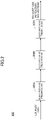
- FIG. 2 is a diagram depicting an example of the electrostatic precipitator 200 according to the first embodiment.
- FIG. 3 is a diagram illustrating an example of a configuration of each of electrostatic precipitators 200A to 200C.
- FIG. 4 is a diagram illustrating an example of the structure of a charging portion 210 (charging electrodes 212 and 214). Specifically, FIG. 4 is a front view of the charging electrodes 212 and 214 viewed along the direction of a flow.
- the electrostatic precipitator 200 includes the electrostatic precipitators 200A to 200C.
- the electrostatic precipitators 200A to 200C may be referred to collectively or individually as “electrostatic precipitator 200X”.
- the electrostatic precipitators 200A to 200C are arranged in series with respect to a flow of an exhaust gas. Specifically, an exhaust gas discharged from the main engine 100 flows into the electrostatic precipitator 200A through an exhaust pipe, the exhaust gas passed through the electrostatic precipitator 200A flows into the electrostatic precipitator 200B, and the exhaust gas passed through the electrostatic precipitator 200B flows into the electrostatic precipitator 200C.
- the exhaust gas passed through the electrostatic precipitator 200C that is, the exhaust gas passed through the electrostatic precipitator 200, is introduced to the scrubber 300 through the exhaust pipe as described above.
- each of the electrostatic precipitators 200A to 200C includes a charging portion 210 and a collection portion 220.
- the electrostatic precipitators 200A to 200C also include a controller 230.
- the single controller 230 may be provided for the electrostatic precipitators 200A to 200C.
- the charging portion 210 includes charging electrodes 212 and 214 and a DC power supply 216.
- the charging electrodes 212 and 214 are arranged opposite to each other, and generate a corona discharge therebetween according to a voltage applied by the DC power supply 216. This allows the particulate matter passing through the charging portion 210 to be electrified (charged).
- the charging electrodes 212 and 214 may be formed of an electrically conductive material such as stainless steel, tungsten, titanium, or carbon material. Hereinafter, the same may apply to the collection electrodes 222 and 224 described later.
- the DC power supply 216 applies a voltage to generate a corona discharge between the charging electrodes 212 and 214.
- the positive electrode of the DC power supply 216 is connected to the charging electrode 214 and grounded, and the negative electrode of the DC power supply 216 is connected to the charging electrode 212.
- a negative voltage is applied between the charging electrodes 212 and 214 such that the charging electrode 214 is set to the reference potential (ground potential) and the charging electrode 212 is set to a negative high potential.
- a corona discharge is generated from the charging electrode 212, and thereby the particulate matter of the exhaust gas passing between the charging electrodes 212 and 214 is negatively charged.
- the negative electrode of the DC power supply 216 may be, on the other hand, connected to the charging electrode 214 and grounded, and the positive electrode of the DC power supply 216 may be connected to the charging electrode 212.
- a positive voltage is applied between the charging electrodes 212 and 214 such that the charging electrode 214 is set to the reference potential and the charging electrode 212 is set to a positive high potential.
- a corona discharge is generated from the charging electrode 212, and thereby the particulate matter of the exhaust gas passing between the charging electrodes 212 and 214 is positively charged.
- the charging electrodes 212 and 214 may be configured as a pair of a discharging electrode and a counter electrode of a cylindrical coaxial system (hereinafter, referred to as a "cylindrical coaxial electrode pair"), for example, as shown in FIGS. 3 and 4 .
- the charging electrode 214 as the counter electrode may have a substantially cylindrical inner peripheral surface extending along the direction of the flow of the exhaust gas
- the charging electrode 212 as the discharge electrode may have an elongated shape so as to extend along the central axis of the inner peripheral surface of the charging electrode 214.
- the term "substantially” is intended, for example, to allow manufacturing errors, and will be used hereinafter in the same sense.
- a distance (gap length) between the charging electrode 214 of the reference potential side and the charging electrode 212 of the high voltage side is substantially uniform at any position. Therefore, it is possible to avoid transition to a spark discharge and form a stable corona discharge.
- the charging electrode 212 and the charging electrode 214 are provided to extend in the direction of the flow of the exhaust gas, so that a pressure loss in the charging portion 210 can be reduced.
- the charging electrode 214 has a plurality of substantially cylindrical inner peripheral surfaces arranged in parallel with respect to the direction of the flow of the exhaust gas, each having a corresponding charging electrode 212 interposed therein, so that cylindrical coaxial electrode pairs are configured.
- the stable corona discharge is realized, and a flow area of the exhaust gas is secured while a dimension in the flow direction of the exhaust gas of the charging portion 210 is maintained, so that the pressure loss can be further reduced and the flow rate of the exhaust gas can be made relatively larger.
- the collection portion 220 is disposed adjacent to the charging portion 210 on the downstream side of the flow of the exhaust gas.
- the collection portion 220 includes the collection electrodes 222 and 224, and a DC power supply 226.
- the collection electrodes 222 and 224 are arranged opposite to each other, and a voltage is applied therebetween by the DC power supply 226 to exert a Coulomb force on the particulate matter in the exhaust gas charged by the charging portion 210 and collect the particulate matter onto the collection electrode 224.
- the DC power supply 226 applies a voltage between the collection electrodes 222 and 224, to generate an electric field between the collection electrodes 222 and 224.
- the DC power supply 226 is provided separately from the DC power supply 216 which applies a voltage to the charging portion 210 (charging electrodes 212 and 214). Specifically, the positive electrode of the DC power supply 226 is connected to the collection electrode 224 and grounded, and the negative electrode of the DC power supply 226 is connected to the collection electrode 222. Thus, a negative voltage is applied between the collection electrodes 222 and 224 such that the collection electrode 224 is set to the reference potential (ground potential) and the collection electrode 222 is set to a negative high potential.
- the positive electrode of the DC power supply 226 may be connected to the collection electrode 224, and the negative electrode of the DC power supply 226 may be connected to the collection electrode 222 and grounded.
- a positive voltage is applied between the collection electrodes 222 and 224 such that the collection electrode 222 is set to the reference potential (ground potential) and the collection electrode 224 is set to a positive high potential. Therefore, when the particulate matter negatively charged in the charging portion 210 enters between the collection electrodes 222 and 224, a Coulomb force drawn into the collection electrode 224 having the positive high potential acts on the particulate matter, and the particulate matter is collected into the collection electrode 224.
- the DC power supply 226 may apply a voltage between the collection electrodes 222 and 224 such that an electric field from the collection electrode 224 to the collection electrode 222 is applied.
- the DC power supply 226 may apply a voltage between the collection electrodes 222 and 224 such that an electric field from the collection electrode 222 to the collection electrode 224 is applied.
- the positive electrode of the DC power supply 226 may be connected to the collection electrode 222, the negative electrode of the DC power supply 226 may be connected to the collection electrode 224, and either of them may be grounded.
- Each of the collection electrodes 222 and 224 may have a shape of a flat plate extending along the direction of the flow of the exhaust gas, for example, as shown in FIG. 3 .
- the controller 230 controls the DC power supplies 216 and 226.
- the controller 230 is implemented as a function of any hardware or any combination of hardware and software.
- the controller 230 is configured mainly by a computer including a memory device such as a CPU (Central Processing Unit), a RAM (Random Access Memory), a non-volatile auxiliary storage device such as a ROM (Read Only Memory), an input/output (I/O) interface device, and the like.
- Various signals used for controlling the DC power supplies 216 and 226 are input to the controller 230.
- a signal corresponding to a measured value of a temperature (exhaust gas temperature) of the exhaust gas flowing into the electrostatic precipitator 200 from a temperature sensor located near the inlet of the exhaust gas of the electrostatic precipitator 200 may be input to the controller 230.
- a signal relating to a load factor (engine load factor) of the main engine 100 may be input to the controller 230 from another controller which controls the main engine 100.
- the controller 230 may be input with a signal corresponding to a measured value of a temperature (engine temperature) of a predetermined portion of the main engine 100 from a temperature sensor installed in the predetermined portion of the main engine 100 (e.g., an exhaust manifold).
- the controller 230 may be input with a signal corresponding to a measured value of a temperature (precipitator temperature) of a predetermined portion of the electrostatic precipitator 200 from a temperature sensor installed in the predetermined portion of the electrostatic precipitator 200 (e.g., a housing of the electrostatic precipitator 200A).
- the controller 230 may be input with a signal corresponding to a measured value of a temperature of an exhaust pipe (exhaust pipe temperature) from a temperature sensor installed in the exhaust pipe between the main engine 100 and the electrostatic precipitator 200.
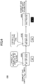
- FIGS. 5 to 7 are diagrams illustrating examples of a control method of the electrostatic precipitator 200. Specifically, FIGS. 5 to 7 illustrate an example, another example, and yet another example of an operating state of the electrostatic precipitator 200, respectively.
- the controller 230 changes the number of electrostatic precipitators 200X in operation among the electrostatic precipitators 200A and 200C according to the temperature state of the exhaust gas flowing into the electrostatic precipitator 200 (i.e., the exhaust gas flowing into the first stage electrostatic precipitator 200A).
- the controller 230 causes the electrostatic precipitator 200A to operate and causes the electrostatic precipitators 200B and 200C not to operate when the temperature Teg of the exhaust gas flowing into the electrostatic precipitator 200 is lower than 100°C. Specifically, the controller 230 controls the DC power supplies 216 and 226 of the electrostatic precipitator 200A to apply a voltage to the charging electrodes 212 and 214 and the collection electrodes 222 and 224 of the electrostatic precipitator 200A. Thus, the electrostatic precipitator 200A can collect particulate matter in the exhaust gas. On the other hand, the controller 230 causes the DC power supplies 216 and 226 of the electrostatic precipitators 200B and 200C to stop operating. Thus, no voltage is applied to the charging electrodes 212 and 214 and the collection electrodes 222 and 224 of the electrostatic precipitators 200B and 200C. The electrostatic precipitators 200B and 200C do not collect particulate matter in the exhaust gas.
- An exhaust gas of the main engine 100 may include, for example, BC, calcium sulfate, and VOC.
- BC calcium sulfate
- VOC is likely to be present in the exhaust gas as a particulate matter without vaporization.
- the temperature Teg of the exhaust gas flowing into the electrostatic precipitator 200 is lower than 100°C, the formation of calcium sulfate by the combination of calcium and sulfate ion contained in the exhaust gas progresses, and calcium sulfate is likely to be contained in the exhaust gas.
- BC is present as a particulate matter regardless of the temperature Teg of the exhaust gas. Therefore, the electrostatic precipitator 200 can cause only the electrostatic precipitators 200A to operate among the electrostatic precipitators 200A to 200C to collect particulate matter containing BC, calcium sulfate, and VOC in the passing exhaust gas.
- the controller 230 causes the electrostatic precipitators 200A and 200B to operate and causes the electrostatic precipitator 200C not to operate when the temperature Teg of the exhaust gas flowing into the electrostatic precipitator 200 is higher than or equal to 100°C and lower than 300°C.
- the controller 230 controls the respective DC power supplies 216 and 226 of the electric precipitators 200A and 200B to apply voltages to the charging electrodes 212 and 214 and the collection electrodes 222 and 224 of the electric precipitators 200A and 200B.
- the electrostatic precipitators 200A and 200B can collect particulate matter in the exhaust gas.
- the controller 230 causes the DC power supplies 216 and 226 of the electrostatic precipitator 200C to stop operating.
- no voltage is applied to the charging electrodes 212 and 214 and the collection electrodes 222 and 224 of the electrostatic precipitator 200C, and the electrostatic precipitator 200C does not collect particulate matter in the exhaust gas.
- the VOC is likely to vaporize and not to be present as a particulate matter.
- the temperature Teg of the exhaust gas flowing into the electrostatic precipitator 200 is lower than 300°C, the formation of calcium sulfate by the combination of calcium and sulfate ion contained in the exhaust gas progresses, and calcium sulfate is likely to be contained in the exhaust gas.
- BC is present as a particulate matter regardless of the temperature Teg of the exhaust gas. Therefore, the electrostatic precipitator 200A can collect particulate matter containing BC and calcium sulfate from the exhaust gas at the temperature of higher than or equal to 100°C and lower than 300°C.
- the electrostatic precipitator 200B can collect particulate matter containing VOC from the exhaust gas whose temperature has become lower than 100°C.
- the electrostatic precipitator 200 can operate only the electrostatic precipitators 200A and 200B among the electrostatic precipitators 200A and 200C to collect particulate matter containing BC, calcium sulfate, and VOC in the passing exhaust gas.
- the controller 230 causes all of the electrostatic precipitators 200A to 200C to operate when the temperature Teg of the exhaust gas flowing into the electrostatic precipitator 200 is higher than or equal to 300°C. Specifically, the controller 230 controls the respective DC power supplies 216 and 226 of the electrostatic precipitators 200A to 200C to apply a voltage to the charging electrodes 212 and 214 and the collection electrodes 222 and 224 of the electrostatic precipitators 200A to 200C.
- the electrostatic precipitators 200A to 200C can collect particulate matter in the exhaust gas.
- the VOC is likely to vaporize and not to be present as a particulate matter.
- the temperature Teg of the exhaust gas flowing into the electrostatic precipitator 200 is higher than or equal to 300°C
- the formation of calcium sulfate by the combination of calcium and sulfate ion contained in the exhaust gas is difficult to progress, and calcium sulfate is unlikely to be contained in the exhaust gas.
- BC is present as a particulate matter regardless of the temperature Teg of the exhaust gas. Therefore, the electrostatic precipitator 200A can collect a particulate matter containing BC from the exhaust gas at a temperature of higher than or equal to 300°C.
- the electrostatic precipitator 200B can collect a particulate matter containing calcium sulfate from the exhaust gas whose temperature has become lower than 300°C.
- the electrostatic precipitator 200C can collect particulate matter containing VOC from the exhaust gas whose temperature has become lower than 100°C.
- the electrostatic precipitator 200 can operate all of the electrostatic precipitators 200A to 200C to collect particulate matter containing BC, calcium sulfate, and VOC in the passing exhaust gas.
- the controller 230 varies the number of electrostatic precipitators in operation among the electrostatic precipitators 200A to 200C in accordance with the temperature Teg of the exhaust gas flowing into the electrostatic precipitator 200.
- the particulate matter to be collected in the exhaust gas can be more appropriately collected, and the energy consumption (power consumption) can be suppressed, thereby achieving energy savings.
- the controller 230 may change the number of electrostatic precipitators 200X in operation of the electrostatic precipitators 200A to 200C based on a measured value of the temperature Teg of the exhaust gas flowing into the electrostatic precipitator 200.
- the controller 230 may estimate the temperature Teg of the exhaust gas flowing into the electrostatic precipitator 200 based on, for example, a temperature (measurement) of an exhaust gas measured by a temperature sensor installed further upstream from an inlet of the electrostatic precipitator 200 and may utilize the estimated value.
- the controller 230 may also estimate the temperature of the exhaust gas from other information as described below.
- controller 230 may change the number of electrostatic precipitators 200X in operation of the electrostatic precipitators 200A to 200C according to the state of the main engine 100 associated with the temperature of the exhaust gas.
- the controller 230 may, for example, change the number of electrostatic precipitators 200X in operation of the electrostatic precipitators 200A to 200C according to the load state (e.g., engine load factor) of the main engine 100. This is because when the load of the main engine 100 is relatively small (low), the temperature of the exhaust gas decreases, and when the load of the main engine 100 is relatively large (high), the temperature of the exhaust gas becomes relatively high.
- the load state e.g., engine load factor
- the controller 230 may cause only the electrostatic precipitator 200A among the electrostatic precipitators 200A to 200C to operate when the load factor of the main engine 100 is lower than a predetermined value LF1.
- the controller 230 may cause only the electrostatic precipitators 200A and 200B among the electrostatic precipitators 200A and 200C to operate when the load factor of the main engine 100 is greater than or equal to the predetermined value LF1 and less than a predetermined value LF2 (>LF1).
- the controller 230 may cause all of the electrostatic precipitators 200A to 200C to operate when the load factor of the main engine 100 is greater than or equal to the predetermined value LF2.
- the predetermined values LF1 and LF2 correspond to the load factor of the main engine 100 when the temperature of the exhaust gas flowing into the electrostatic precipitator 200 is 100°C and 300°C, respectively.
- the load factor information of the main engine 100 may be obtained from the other controller controlling the main engine 100 as described above. Further, data on the operation status of the main engine 100 may be acquired from the other controller by the controller 230, and the controller 230 may calculate the load factor of the main engine 100 from the data on the acquired operation status.
- the controller 230 may, for example, change the number of electrostatic precipitators 200X in operation among the electrostatic precipitators 200A to 200C according to the temperature state of a predetermined portion of the main engine 100. This is because when the temperature of the exhaust gas of the main engine 100 is relatively low, the temperature of the main engine 100 itself is relatively low, and when the temperature of the exhaust gas of the main engine 100 is relatively high, the temperature of the main engine 100 itself is relatively high.
- the controller 230 may cause only the electrostatic precipitator 200A among the electrostatic precipitators 200A to 200C to operate when the temperature of the predetermined portion of the main engine 100 (engine temperature) is lower than a predetermined value ET1.
- the controller 230 may cause only the electrostatic precipitators 200A and 200B among the electrostatic precipitators 200A and 200C to operate when the engine temperature is higher than or equal to the predetermined value ET1 and lower than a predetermined value ET2 (>ET1).
- the controller 230 may cause all of the electrostatic precipitators 200A to 200C to operate when the engine temperature is higher than or equal to the predetermined value ET2.
- the predetermined values ET1 and ET2 correspond to the engine temperatures when the temperature of the exhaust gas flowing into the electrostatic precipitator 200 is 100°C and 300°C, respectively.
- the temperature of the predetermined portion of the main engine 100 is measured by the temperature sensor installed in the main engine 100 as described above, and a signal corresponding to the measured value may be input to the controller 230.
- the controller 230 may estimate the temperature of the exhaust gas flowing into the electrostatic precipitator 200 based on the load factor of the main engine 100, the temperature state of the predetermined portion, or the like. The controller 230 may then change the number of electrostatic precipitators 200X in operation among the electrostatic precipitators 200A to 200C in the same manner as described above according to the estimated value of the temperature of the exhaust gas flowing into the electrostatic precipitator 200.
- the controller 230 may change the number of electrostatic precipitators 200X in operation among the electrostatic precipitators 200A to 200C according to a temperature of a predetermined portion of the exhaust pipe between the main engine 100 and the electrostatic precipitator 200 (exhaust pipe temperature).
- the controller 230 may also change the number of electrostatic precipitators 200X in operation among electrostatic precipitators 200A to 200C according to a temperature of a predetermined portion of the electrostatic precipitator 200 (precipitator temperature). This is because when the temperature of the exhaust gas of the main engine 100 is relatively low, the temperatures of the exhaust pipe and the electrostatic precipitator 200 are relatively low, and when the temperature of the exhaust gas of the main engine 100 is relatively high, the temperatures of the exhaust pipe and the electrostatic precipitator 200 are relatively high.
- the controller 230 may cause only the electrostatic precipitator 200A among the electrostatic precipitators 200A to 200C to operate when the exhaust pipe temperature is lower than a predetermined value XT1.
- the controller 230 may cause only the electrostatic precipitators 200A and 200B among the electrostatic precipitators 200A to 200C to operate when the exhaust pipe temperature is higher than or equal to the predetermined value XT1 and lower than a predetermined value XT2 (>XT1).
- the controller 230 may cause all of the electrostatic precipitators 200A to 200C to operate when the exhaust pipe temperature is higher than or equal to the predetermined value XT2.
- the predetermined values XT1 and XT2 correspond to the exhaust pipe temperatures when the temperature of the exhaust gas flowing into the electrostatic precipitator 200 is 100°C and 300°C, respectively. The same method may be employed when the precipitator is controlled according to the precipitator temperature.
- the controller 230 may estimate the temperature of the exhaust gas flowing into the electrostatic precipitator 200 based on the temperature of the exhaust pipe or the precipitator temperature. The controller 230 may then change the number of electrostatic precipitators 200X in operation among the electrostatic precipitators 200A to 200C in the same manner as described above according to the estimated value of the temperature of the exhaust gas flowing into the electrostatic precipitator 200.
- FIGS. 8 to 10 a second embodiment will be described with reference to FIGS. 8 to 10 .
- parts different from the first embodiment will be mainly described, and the description for the same/corresponding contents as/to the first embodiment may be simplified or omitted.
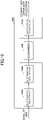
- FIGS. 8 to 10 are diagrams illustrating an example, another example, and yet another example of the electrostatic precipitator 200 according to the second embodiment.
- an economizer 500 is provided in a stage prior to at least one of the electrostatic precipitators 200A to 200C with respect to the flow of the exhaust gas of the main engine 100.
- the economizer 500 (an example of a heat exchanger) is a heat exchanger that absorbs heat.
- the economizer 500 is used, for example, to preheat distilled water used in a boiler mounted on a ship.
- the economizer 500 draws heat from the exhaust gas of the main engine 100 and raises a temperature of the distilled water flowing therein.
- the economizer 500 may be disposed, for example, in the stage prior to the electrostatic precipitator 200A with respect to the flow of the exhaust gas of the main engine 100.
- the temperature of the exhaust gas flowing into each of the electrostatic precipitators 200A to 200C to can be made relatively low. Therefore, the electrostatic precipitator 200, by utilizing the electrostatic precipitators 200A to 200C, can more easily collect the collection target which is not present as a particulate matter at relatively high temperatures (e.g., VOC, or calcium sulfate).
- the economizer 500 may be disposed, for example, on an exhaust path between the electrostatic precipitator 200A and the electrostatic precipitator 200B.
- the temperature of the exhaust gas flowing into each of the electrostatic precipitators 200B and 200C can be made relatively low. Therefore, the electrostatic precipitator 200, by utilizing the electrostatic precipitators 200B and 200C, can more easily collect the collection target which is not present as a particulate matter at relatively high temperatures (for example, VOC, or calcium sulfate).
- the standard of the heat resistance required for the economizer 500 can be made relatively low.
- the standard of the corrosion resistance, the resistance to the passing particulate matter, or the like required for the economizer 500 can be made relatively low. Accordingly, while the collection efficiency for the particulate matter by the electrostatic precipitator 200 is relatively improved, the various resistances required for the economizer 500 can be suppressed relatively low, and the cost increase of the economizer 500 can be suppressed.
- the economizer 500 may be disposed, for example, on an exhaust path between the electrostatic precipitator 200B and the electrostatic precipitator 200C.
- the temperature of the exhaust gas flowing into the electrostatic precipitator 200C can be made relatively low. Therefore, the electrostatic precipitator 200, by utilizing the electrostatic precipitator 200C, can more easily collect the collection target which is not present as a particulate matter at relatively high temperature (e.g., VOC, or calcium sulfate).
- relatively high temperature e.g., VOC, or calcium sulfate.
- the exhaust gas from which particulate matter is collected by the electrostatic precipitator 200B, in addition to the electrostatic precipitator 200A, passes through the economizer 500 the standard of the corrosion resistance, the resistance to the passing particulate matter, or the like required for the economizer 500 can be further reduced. Accordingly, while the collection efficiency for the particulate matter by the electrostatic precipitator 200 is relatively improved, the various resistance required for the economizer 500 can be further suppressed, and the cost increase of the economizer 500 can be further suppressed.
- the electrostatic precipitator 200 of the above-described embodiment may be modified or altered accordingly.
- the collection electrodes 222 and 224 may have any form so long as an electric field capable of collecting the charged particulate matter from the exhaust gas can be applied by a voltage applied from the DC power supply 226.
- the collection electrodes 222 and 224 may be configured as a pair of cylindrical coaxial electrodes, as well as the charging electrodes 212 and 214 of the charging portion 210.
- the collection electrode 224 like the charging electrode 214, has a substantially cylindrical inner peripheral surface extending along the flow of the exhaust gas
- the collection electrode 222 like the charging electrode 212, may have an elongated shape extending on the central axis of the inner peripheral surface of the collection electrode 224.
- the collection electrode 224 has a plurality of substantially cylindrical inner circumferential surfaces arranged in parallel with respect to the direction of the flow of the exhaust gas, in the same manner as the charging electrode 214, and a plurality of pairs of cylindrical coaxial electrodes may be configured in such a way that corresponding collection electrodes 222 are interposed therein, respectively.
- the charging electrodes 212 and 214 and the collection electrodes 222 and 224 may be applied with voltages by the same DC power supply.
- the controller 230 may be provided in each of the electrostatic precipitators 200A to 200C.
- one controller 230 of the three controllers 230 may determine, as a master, the number of electrostatic precipitators 200X to operate, and may cause the electrostatic precipitator 200X (DC power supplies 216 and 226), to be controlled, to operate or stop the operation.
- the remaining controllers 230 may cause the electrostatic precipitators 200X (DC power supplies 216 and 226), to be controlled, to operate or stop the operation, according to the determination result of the one controller 230.
- one of the electrostatic precipitators 200A to 200C may be omitted in the electrostatic precipitator 200. That is, the electrostatic precipitator 200 may include two electrostatic precipitators 200X arranged in series with respect to the flow of the exhaust gas. Also, in the above described embodiments, the electrostatic precipitator 200 may include four or more electrostatic precipitators 200X arranged in series with respect to the flow of the exhaust gas.
- the electrostatic precipitator 200 when causing a part of the electrostatic precipitator 200X among the plurality of electrostatic precipitators 200X to operate, the electrostatic precipitator 200 may select any electrostatic precipitator 200X to operate as long as the condition of the number of electrostatic precipitators 200X in operation is satisfied.
- the controller 230 may cause the electrostatic precipitator 200B or the electrostatic precipitator 200C to operate instead of the electrostatic precipitator 200A.
- the controller 230 may cause the combination of the electrostatic precipitators 200A and 200C or the combination of the electrostatic precipitators 200B and 200C to operate instead of the combination of the electrostatic precipitators 200A and 200B.
- the electrostatic precipitator 200X may be configured to include a charging electrode, a collection electrode facing the charging electrode, and a DC power supply that applies a voltage between the electrodes.
- the electrostatic precipitator 200X applies a voltage between a single charging electrode and a single collection electrode by setting the single collection electrode to a reference potential, and thereby generating a corona discharge from the single charging electrode and charging particulate matter in the exhaust gas.
- the charged particulate matter is collected by the single collection electrode facing the single charging electrode by an action of a Coulomb force, ionic wind, or the like.
- a boundary value on the lower temperature side of the temperature of the exhaust gas for changing the number of electrostatic precipitators 200X to operate may be set within a predetermined range before and after 100°C instead of at 100°C.
- This predetermined range may, for example, exceed or be less than 100°C by 10°C, i.e., in the range of from 90°C to 110°C.
- a boundary value on the higher temperature side of the temperature of the exhaust gas for changing the number of electrostatic precipitators 200X to operate may be set within a predetermined range before and after 300°C instead of at 300°C.
- This predetermined range may, for example, exceed or be less than 300°C by 10°C, i.e., in the range of from 290°C to 310°C.
- a boundary value of the temperature of the exhaust gas for switching in the case of switching to a direction of increasing the number of electrostatic precipitators 200X in operation may be different from a boundary value of the temperature of the exhaust gas for switching in the case of switching to a direction of decreasing the number of electrostatic precipitators 200X in operation.
- the controller 230 may increase the number of electrostatic precipitators 200X in operation when the temperature of the exhaust gas changes from a state of lower than 100°C to a state of higher than or equal to 100°C.
- the controller 230 may decrease the number of electrostatic precipitators 200X in operation when the temperature of the exhaust gas changes from a state of higher than or equal to a predetermined temperature, which is lower than 100°C (for example, 95°C) to a state of lower than the predetermined temperature. Similarly, the controller 230 may increase the number of electrostatic precipitators 200X in operation when the temperature of the exhaust gas changes from a state of lower than 300°C to a state of higher than or equal to 300°C.
- the controller 230 may decrease the number of electrostatic precipitators 200X in operation when the temperature of the exhaust gas changes from a state of higher than or equal to a predetermined temperature, which is lower than 300°C (for example, 295°C) to a state of lower than the predetermined temperature.
- a predetermined temperature which is lower than 300°C (for example, 295°C) to a state of lower than the predetermined temperature.
- the electrostatic precipitator 200 may change the number of electrostatic precipitators 200X in operation among the plurality of electrostatic precipitators 200X according to other conditions in place of the temperature state of the exhaust gas flowing into the electrostatic precipitator 200.
- the electrostatic precipitator 200 may change the number of electrostatic precipitators 200X in operation among the plurality of electrostatic precipitators 200X according to results of analysis of numbers, types, or the like of particulate matter remaining in the exhaust gas after passing through the first stage electrostatic precipitator 200X.
- the electrostatic precipitator 200 when the electrostatic precipitator 200 includes four or more electrostatic precipitators 200X arranged in series with respect to the flow of the exhaust gas, the number of electrostatic precipitators 200X in operation may be changed in four or more stages. Further, in the above-described embodiment or variation thereof, the electrostatic precipitator 200 may change the number of electrostatic precipitators 200X in operation in two steps.
- the exhaust pipe connecting the main engine 100 and the electrostatic precipitator 200 and the exhaust pipe connecting the plurality of electrostatic precipitators 200X included in the electrostatic precipitator 200 may be arranged to pass through a place exposed to the open air (e.g., a deck of a ship).
- the temperature of the exhaust gas passing through the exhaust pipe can be relatively lowered because the exhaust pipe is exposed to the open air. Therefore, the electrostatic precipitator 200 can more easily collect the collection target which is not present as a particulate matter at relatively high temperatures (for example, VOC, or calcium sulfate). Therefore, the electrostatic precipitator 200 facilitates further trapping of a type of trapping object (e.g., VOC, calcium sulfate, etc.) that is not present as a particulate matter at relatively high temperatures.
- a type of trapping object e.g., VOC, calcium sulfate, etc.
- the electrostatic precipitator 200 may collect particulate matter contained in an exhaust gas from an engine disposed at a different location from the ship.
- the electrostatic precipitator 200 may collect particulate matter contained in a gas different from the engine exhaust gas.
- the electrostatic precipitator 200 includes the plurality of electrostatic precipitators 200X (e.g., the electrostatic precipitators 200A to 200C).
- each of the plurality of electrostatic precipitators 200X includes the charging electrodes 212 and 214 and collection electrodes 222 and 224.
- the charging electrodes 212 and 214 generate a corona discharge to charge particulate matter contained in an exhaust gas of the main engine 100.
- the collection electrodes 222 and 224 collect by a Coulomb force the charged particulate matter under the corona discharge.
- the plurality of electrostatic precipitators 200X are arranged in series with respect to the flow of the exhaust gas.
- the electrostatic precipitator 200 can use a downstream electrostatic precipitator 200X. Accordingly, the electrostatic precipitator 200, by using the downstream electrostatic precipitator 200X, can collect the collection target of the type that is not present as a particulate matter at a relatively high temperature. This is because during the process of the exhaust gas flowing downstream the temperature decreases, and the collection target of the type is likely to be present as particulate matter. Accordingly, the electrostatic precipitator 200 can more appropriately collect particulate matter contained in the exhaust gas of the main engine 100.
- each of the plurality of electrostatic precipitators 200X may include a charging portion 210 and a collection portion 220.
- the charging portion 210 may have two charging electrodes 212 and 214, opposite to each other, and the collection portion 220 may be disposed adjacent to the charging portion 210 on the downstream side with respect to the flow of the exhaust gas and may have two collection electrodes 222 and 224, opposite to each other.
- the electrostatic precipitator 200 can separate the function of charging particulate matter in the passing exhaust gas from the function of collecting the charged particulate matter, in the direction of the flow of the exhaust gas, in each of the plurality of electrostatic precipitators 200X. Therefore, the electrostatic precipitator 200 can optimize a size of the portion for each function. Accordingly, the electrostatic precipitator 200 may include the plurality of electrostatic precipitators 200X arranged in series with respect to the flow of the exhaust gas while suppressing an increase in the size of the electrostatic precipitator 200 in the direction of the flow of the exhaust gas.
- all of the plurality of electrostatic precipitators 200X may operate, or a part of the plurality of electrostatic precipitators 200X may operate.
- the electrostatic precipitator 200 can cause only a part of the electrostatic precipitators 200X to operate and stop the operation of the remaining electrostatic precipitator 200X. Therefore, the electrostatic precipitator 200 can suppress the energy consumption (power consumption) while more appropriately collecting particulate matter contained in the exhaust gas of the main engine 100.
- the electrostatic precipitator 200 (controller 230) may vary the number of electrostatic precipitators 200X in operation among the plurality of electrostatic precipitators 200X according to the temperature state of the exhaust gas.
- the electrostatic precipitator 200 can adjust the number of electrostatic precipitators 200X in operation in consideration of the state of the collection target contained in the exhaust gas flowing into the electrostatic precipitator 200 based on the temperature state of the exhaust gas.
- the electrostatic precipitator 200 (controller 230) may vary the number of electrostatic precipitators 200X in operation among the plurality of electrostatic precipitators 200X according to the state of the main engine 100 associated with the temperature state of the exhaust gas.
- the electrostatic precipitator 200 can adjust the number of electrostatic precipitators 200X in operation in consideration of the state of the collection target contained in the exhaust gas flowing into the electrostatic precipitator 200 based on the state of the main engine 100 associated with the temperature state of the exhaust gas.
- the electrostatic precipitator 200 (controller 230) may vary the number of electrostatic precipitators 200X in operation among the plurality of electrostatic precipitators 200X according to the load state of the main engine 100 or the temperature state of the predetermined portion of the main engine 100.
- the electrostatic precipitator 200 can adjust the number of electrostatic precipitators 200X in operation in consideration of the state of the collection target contained in the exhaust gas flowing into the electrostatic precipitator 200 based on the load state of the main engine 100 and the temperature state of the predetermined portion of the main engine 100.
- the electrostatic precipitator 200 may vary the number of electrostatic precipitators 200X in operation among the plurality of electrostatic precipitators 200X according to the temperature state of at least one of an inflow path of the exhaust gas and the predetermined portion of the electrostatic precipitator 200.
- the electrostatic precipitator 200 can adjust the number of electrostatic precipitators 200X in operation in consideration of the state of the collection target contained in the exhaust gas flowing into the electrostatic precipitator 200 based on the temperature state of the inflow path of the exhaust gas (exhaust pipe) and the predetermined portion of the electrostatic precipitator 200.
- the electrostatic precipitator 200 (controller 230) may increase the number of electrostatic precipitators 200X in operation among the plurality of electrostatic precipitators 200X, as the temperature of the exhaust gas becomes relatively higher.
- the electrostatic precipitator 200 can specifically adjust the number of electrostatic precipitators 200X in operation in consideration of the state of the collection target contained in the exhaust gas flowing into the electrostatic precipitator 200.
- the electrostatic precipitator 200 may change the number of electrostatic precipitators 200X in operation among the plurality of electrostatic precipitators 200X when the temperature of the exhaust gas flowing into the electrostatic precipitator 200 becomes a reference temperature on the low temperature side (an example of a first reference temperature) set within a predetermined range before and after 100°C, as a boundary.
- a reference temperature on the low temperature side an example of a first reference temperature
- the electrostatic precipitator 200 can suppress the energy consumption (power consumption) while appropriately collecting VOC, in which the state of being present as gas transits to the state of being present as particulate matter at a temperature of about 100°C as a boundary.
- the electrostatic precipitator 200 may change the number of electrostatic precipitators 200X in operation among the plurality of electrostatic precipitators 200X when the temperature of the exhaust gas flowing into the plurality of electrostatic precipitators 200X becomes a reference temperature on the high temperature side (an example of a second reference temperature) set within a predetermined range before and after 300°C, as a boundary.
- a reference temperature on the high temperature side an example of a second reference temperature
- the electrostatic precipitator 200 can suppress the energy consumption (power consumption) while appropriately collecting calcium sulfate in which the state of combination of calcium and sulfate ion being difficult to progress transmits to the state of combination of calcium and sulfate ion being easy to progress at a temperature of about 300°C as a boundary.
- the economizer 500 for absorbing heat may be disposed in a stage prior to at least one of the plurality of electrostatic precipitators 200X with respect to the flow of the exhaust gas.
- the temperature of the exhaust gas flowing into the electrostatic precipitator 200X located in a stage coming after the economizer 500 among the plurality of electrostatic precipitators 200X can be further reduced. Therefore, the electrostatic precipitator 200 can more appropriately collect particulate matter contained in the exhaust gas of the main engine 100.
- the charging electrode 214 having a reference potential of the two charging electrodes 212 and 214 may have a substantially cylindrical inner peripheral surface extending in the direction of the flow of the gas.
- the charging electrode 212 with the higher potential of the charging electrodes 212 and 214 may be disposed to extend in the direction of the flow of the gas substantially coaxially with the inner peripheral surface of the charging electrode 214.
- the electrostatic precipitator 200 can suppress the pressure loss of the gas passing through the charging portion 210.
- the electrostatic precipitator 200 can avoid the transition to the spark discharge and form a stable corona discharge.
Landscapes
- Engineering & Computer Science (AREA)
- Chemical & Material Sciences (AREA)
- Combustion & Propulsion (AREA)
- Mechanical Engineering (AREA)
- General Engineering & Computer Science (AREA)
- Health & Medical Sciences (AREA)
- Chemical Kinetics & Catalysis (AREA)
- Toxicology (AREA)
- Ocean & Marine Engineering (AREA)
- Electrostatic Separation (AREA)
- Processes For Solid Components From Exhaust (AREA)
Abstract
Description
- The present disclosure relates to an electrostatic precipitator.
- For example, an electrostatic precipitator that charges particulate matter (PM) contained in a gas by corona discharge and collects the charged particulate matter by a Coulomb force or the like has been known (see Patent Document 1).
- Patent Document 1:
Japanese Patent No. 3648679 - Incidentally, an exhaust gas from an engine can include various types of particulate matter to be collected, such as black carbon (BC), a volatile organic compound (VOC), and calcium sulfate.
- However, depending on a type of particulate matter, a change in a temperature state of the exhaust gas can cause a change in the form. For example, when a temperature of the exhaust gas rises to a certain degree, volatilization of a VOC may become active and the VOC may turn into a vaporized state. For example, when a temperature of the exhaust gas becomes higher, a formation of calcium sulfate due to a combination of calcium contained in an engine oil and a sulfate ion generated from a sulfur component of a fuel may not progress. Therefore, depending on the temperature of the exhaust gas, it may not be possible to properly collect particulate matter to be collected.
- Therefore, in view of the above-described problem, the present disclosure aims at providing a technology capable of more appropriately collecting a particulate matter.
- In order to accomplish the above-described purpose, according to an aspect of the present disclosure,
- an electrostatic precipitator including
- a plurality of precipitation portions, each including
- a charging electrode configured to charge a particulate matter contained in an exhaust gas from an engine by generating a corona discharge; and
- a collection electrode configured to collect by a Coulomb force the particulate matter charged by the corona discharge,
- the precipitation portions being arranged in series with respect to a flow of the exhaust gas, is provided.
- In accordance with the above-described embodiments, particulate matter can be collected more appropriately.
-
- [
Figure 1] FIG. 1 is a diagram depicting an example of an exhaust gas purification system including an electrostatic precipitator. - [
Figure 2] FIG. 2 is a diagram depicting an example of an electrostatic precipitator according to a first embodiment. - [
Figure 3] FIG. 3 is a diagram depicting an example of a configuration of the electrostatic precipitator. - [
Figure 4] FIG. 4 is a diagram depicting an example of a structure of a charging electrode. - [
Figure 5] FIG. 5 is a diagram illustrating a control method of the electrostatic precipitator. - [
Figure 6] FIG. 6 is a diagram illustrating a control method of the electrostatic precipitator. - [
Figure 7] FIG. 7 is a diagram illustrating a control method of the electrostatic precipitator. - [
Figure 8] FIG. 8 is a diagram depicting an example of an electrostatic precipitator according to a second embodiment. - [
Figure 9] FIG. 9 is a diagram depicting another example of the electrostatic precipitator according to the second embodiment. - [
Figure 10] FIG. 10 is a diagram depicting yet another example of the electrostatic precipitator according to the second embodiment. - Hereinafter, embodiments will be described with reference to the drawings.
- A first embodiment will be described with reference to
FIGS. 1 to 7 . -
FIG. 1 is a diagram depicting an example of an exhaustgas purification system 1 including anelectrostatic precipitator 200 according to the first embodiment. - The exhaust
gas purification system 1 is loaded in a ship. Hereinafter, "ship" means, unless otherwise specified, a ship in which anelectrostatic precipitator 200 is loaded. - As shown in
FIG. 1 , the exhaustgas purification system 1 includes amain engine 100, theelectrostatic precipitator 200, ascrubber 300, and apump 400. The exhaustgas purification system 1 purifies an exhaust gas emitted from themain engine 100 and discharges an exhaust gas from a chimney of the ship to the outside. - The main engine 100 (an example of an engine) rotates a propeller to propel the ship. The main engine is, for example, a diesel engine capable of using heavy oil C as a fuel.
- The
electrostatic precipitator 200 collects particulate matter (PM) contained in the exhaust gas of themain engine 100. Exhaust gas collected by the electrostatic precipitator 200 (particulate matter is removed) is fed to thescrubber 300. - The
scrubber 300 sprays seawater supplied through thepump 400 into the exhaust gas of themain engine 100 passing therethrough to absorb sulfur oxide (SOx) contained in themain engine 100 into the seawater. The seawater supplied to thescrubber 300 may be seawater that is constantly pumped out of the sea using an open loop system or seawater that is neutralized and circulated (reused) in a neutralization tank using a closed loop system. The exhaust gas from thescrubber 300 from which SOx components have been removed is released into the atmosphere outside the ship through the chimney of the ship. Seawater that absorbs the SOx components of the exhaust gas discharged from thescrubber 300 is discharged into the sea outside the ship using the open loop system or is returned to the neutralization tank using the closed loop system for reuse. - The
pump 400 pumps seawater into thescrubber 300 from the sea or from the neutralization tank. - Thus, the exhaust
gas purification system 1 can purify the exhaust gas of themain engine 100 using theelectrostatic precipitator 200 and thescrubber 300. -
FIG. 2 is a diagram depicting an example of theelectrostatic precipitator 200 according to the first embodiment.FIG. 3 is a diagram illustrating an example of a configuration of each ofelectrostatic precipitators 200A to 200C.FIG. 4 is a diagram illustrating an example of the structure of a charging portion 210 (charging electrodes 212 and 214). Specifically,FIG. 4 is a front view of thecharging electrodes - As shown in
FIG. 2 , theelectrostatic precipitator 200 includes theelectrostatic precipitators 200A to 200C. Hereinafter, theelectrostatic precipitators 200A to 200C may be referred to collectively or individually as "electrostatic precipitator 200X". - The
electrostatic precipitators 200A to 200C (an example of a plurality of precipitation portions) are arranged in series with respect to a flow of an exhaust gas. Specifically, an exhaust gas discharged from themain engine 100 flows into theelectrostatic precipitator 200A through an exhaust pipe, the exhaust gas passed through theelectrostatic precipitator 200A flows into theelectrostatic precipitator 200B, and the exhaust gas passed through theelectrostatic precipitator 200B flows into theelectrostatic precipitator 200C. The exhaust gas passed through theelectrostatic precipitator 200C, that is, the exhaust gas passed through theelectrostatic precipitator 200, is introduced to thescrubber 300 through the exhaust pipe as described above. - As shown in
FIG. 3 , each of theelectrostatic precipitators 200A to 200C includes acharging portion 210 and acollection portion 220. Theelectrostatic precipitators 200A to 200C also include acontroller 230. Thesingle controller 230 may be provided for theelectrostatic precipitators 200A to 200C. - The charging
portion 210 includes chargingelectrodes DC power supply 216. - The charging
electrodes DC power supply 216. This allows the particulate matter passing through the chargingportion 210 to be electrified (charged). The chargingelectrodes collection electrodes - The
DC power supply 216 applies a voltage to generate a corona discharge between the chargingelectrodes DC power supply 216 is connected to the chargingelectrode 214 and grounded, and the negative electrode of theDC power supply 216 is connected to the chargingelectrode 212. Thus, a negative voltage is applied between the chargingelectrodes electrode 214 is set to the reference potential (ground potential) and the chargingelectrode 212 is set to a negative high potential. Then, a corona discharge is generated from the chargingelectrode 212, and thereby the particulate matter of the exhaust gas passing between the chargingelectrodes - The negative electrode of the
DC power supply 216 may be, on the other hand, connected to the chargingelectrode 214 and grounded, and the positive electrode of theDC power supply 216 may be connected to the chargingelectrode 212. In this case, a positive voltage is applied between the chargingelectrodes electrode 214 is set to the reference potential and the chargingelectrode 212 is set to a positive high potential. Then, a corona discharge is generated from the chargingelectrode 212, and thereby the particulate matter of the exhaust gas passing between the chargingelectrodes - The charging
electrodes FIGS. 3 and4 . Specifically, the chargingelectrode 214 as the counter electrode may have a substantially cylindrical inner peripheral surface extending along the direction of the flow of the exhaust gas, and the chargingelectrode 212 as the discharge electrode may have an elongated shape so as to extend along the central axis of the inner peripheral surface of the chargingelectrode 214. The term "substantially" is intended, for example, to allow manufacturing errors, and will be used hereinafter in the same sense. Thus, a distance (gap length) between the chargingelectrode 214 of the reference potential side and the chargingelectrode 212 of the high voltage side is substantially uniform at any position. Therefore, it is possible to avoid transition to a spark discharge and form a stable corona discharge. The chargingelectrode 212 and the charging electrode 214 (inner peripheral surface) are provided to extend in the direction of the flow of the exhaust gas, so that a pressure loss in the chargingportion 210 can be reduced. - Also, as shown in
FIG. 4 , the chargingelectrode 214 has a plurality of substantially cylindrical inner peripheral surfaces arranged in parallel with respect to the direction of the flow of the exhaust gas, each having acorresponding charging electrode 212 interposed therein, so that cylindrical coaxial electrode pairs are configured. Thus, the stable corona discharge is realized, and a flow area of the exhaust gas is secured while a dimension in the flow direction of the exhaust gas of the chargingportion 210 is maintained, so that the pressure loss can be further reduced and the flow rate of the exhaust gas can be made relatively larger. - The
collection portion 220 is disposed adjacent to the chargingportion 210 on the downstream side of the flow of the exhaust gas. Thecollection portion 220 includes thecollection electrodes DC power supply 226. - The
collection electrodes DC power supply 226 to exert a Coulomb force on the particulate matter in the exhaust gas charged by the chargingportion 210 and collect the particulate matter onto thecollection electrode 224. - The
DC power supply 226 applies a voltage between thecollection electrodes collection electrodes DC power supply 226 is provided separately from theDC power supply 216 which applies a voltage to the charging portion 210 (chargingelectrodes 212 and 214). Specifically, the positive electrode of theDC power supply 226 is connected to thecollection electrode 224 and grounded, and the negative electrode of theDC power supply 226 is connected to thecollection electrode 222. Thus, a negative voltage is applied between thecollection electrodes collection electrode 224 is set to the reference potential (ground potential) and thecollection electrode 222 is set to a negative high potential. Therefore, when the particulate matter negatively charged in the chargingportion 210 enters between thecollection electrodes collection electrode 224 having the reference potential acts on the particulate matter, and the particulate matter is collected into thecollection electrode 224. - The positive electrode of the
DC power supply 226 may be connected to thecollection electrode 224, and the negative electrode of theDC power supply 226 may be connected to thecollection electrode 222 and grounded. Thus, a positive voltage is applied between thecollection electrodes collection electrode 222 is set to the reference potential (ground potential) and thecollection electrode 224 is set to a positive high potential. Therefore, when the particulate matter negatively charged in the chargingportion 210 enters between thecollection electrodes collection electrode 224 having the positive high potential acts on the particulate matter, and the particulate matter is collected into thecollection electrode 224. That is, when the particulate matter is negatively charged by the chargingportion 210, theDC power supply 226 may apply a voltage between thecollection electrodes collection electrode 224 to thecollection electrode 222 is applied. As described above, if the particulate matter is positively charged by the chargingportion 210, theDC power supply 226 may apply a voltage between thecollection electrodes collection electrode 222 to thecollection electrode 224 is applied. Thus, when the particulate matter positively charged in the chargingportion 210 enters between thecollection electrodes collection electrode 224. Specifically, if the particulate matter is positively charged by the chargingportion 210, the positive electrode of theDC power supply 226 may be connected to thecollection electrode 222, the negative electrode of theDC power supply 226 may be connected to thecollection electrode 224, and either of them may be grounded. - Each of the
collection electrodes FIG. 3 . - The
controller 230 controls theDC power supplies controller 230 is implemented as a function of any hardware or any combination of hardware and software. For example, thecontroller 230 is configured mainly by a computer including a memory device such as a CPU (Central Processing Unit), a RAM (Random Access Memory), a non-volatile auxiliary storage device such as a ROM (Read Only Memory), an input/output (I/O) interface device, and the like. - Various signals used for controlling the
DC power supplies controller 230. For example, a signal corresponding to a measured value of a temperature (exhaust gas temperature) of the exhaust gas flowing into theelectrostatic precipitator 200 from a temperature sensor located near the inlet of the exhaust gas of theelectrostatic precipitator 200 may be input to thecontroller 230. For example, a signal relating to a load factor (engine load factor) of themain engine 100 may be input to thecontroller 230 from another controller which controls themain engine 100. For example, thecontroller 230 may be input with a signal corresponding to a measured value of a temperature (engine temperature) of a predetermined portion of themain engine 100 from a temperature sensor installed in the predetermined portion of the main engine 100 (e.g., an exhaust manifold). For example, thecontroller 230 may be input with a signal corresponding to a measured value of a temperature (precipitator temperature) of a predetermined portion of theelectrostatic precipitator 200 from a temperature sensor installed in the predetermined portion of the electrostatic precipitator 200 (e.g., a housing of theelectrostatic precipitator 200A). For example, thecontroller 230 may be input with a signal corresponding to a measured value of a temperature of an exhaust pipe (exhaust pipe temperature) from a temperature sensor installed in the exhaust pipe between themain engine 100 and theelectrostatic precipitator 200. -
FIGS. 5 to 7 are diagrams illustrating examples of a control method of theelectrostatic precipitator 200. Specifically,FIGS. 5 to 7 illustrate an example, another example, and yet another example of an operating state of theelectrostatic precipitator 200, respectively. - The
controller 230 changes the number of electrostatic precipitators 200X in operation among theelectrostatic precipitators electrostatic precipitator 200A). - As shown in
FIG. 5 , thecontroller 230 causes theelectrostatic precipitator 200A to operate and causes theelectrostatic precipitators electrostatic precipitator 200 is lower than 100°C. Specifically, thecontroller 230 controls theDC power supplies electrostatic precipitator 200A to apply a voltage to the chargingelectrodes collection electrodes electrostatic precipitator 200A. Thus, theelectrostatic precipitator 200A can collect particulate matter in the exhaust gas. On the other hand, thecontroller 230 causes theDC power supplies electrostatic precipitators electrodes collection electrodes electrostatic precipitators electrostatic precipitators - An exhaust gas of the
main engine 100 may include, for example, BC, calcium sulfate, and VOC. When the temperature Teg of the exhaust gas flowing into the electrostatic precipitator 200 (i.e., the first stageelectrostatic precipitator 200A) is lower than 100°C, VOC is likely to be present in the exhaust gas as a particulate matter without vaporization. In addition, when the temperature Teg of the exhaust gas flowing into theelectrostatic precipitator 200 is lower than 100°C, the formation of calcium sulfate by the combination of calcium and sulfate ion contained in the exhaust gas progresses, and calcium sulfate is likely to be contained in the exhaust gas. In addition, BC is present as a particulate matter regardless of the temperature Teg of the exhaust gas. Therefore, theelectrostatic precipitator 200 can cause only theelectrostatic precipitators 200A to operate among theelectrostatic precipitators 200A to 200C to collect particulate matter containing BC, calcium sulfate, and VOC in the passing exhaust gas. - As shown in
FIG. 6 , thecontroller 230 causes theelectrostatic precipitators electrostatic precipitator 200C not to operate when the temperature Teg of the exhaust gas flowing into theelectrostatic precipitator 200 is higher than or equal to 100°C and lower than 300°C. Specifically, thecontroller 230 controls the respectiveDC power supplies electric precipitators electrodes collection electrodes electric precipitators electrostatic precipitators controller 230 causes theDC power supplies electrostatic precipitator 200C to stop operating. Thus, no voltage is applied to the chargingelectrodes collection electrodes electrostatic precipitator 200C, and theelectrostatic precipitator 200C does not collect particulate matter in the exhaust gas. - When the temperature Teg of the exhaust gas flowing into the electrostatic precipitator 200 (i.e., the first stage
electrostatic precipitator 200A) is higher than or equal to 100°C, the VOC is likely to vaporize and not to be present as a particulate matter. On the other hand, when the temperature Teg of the exhaust gas flowing into theelectrostatic precipitator 200 is lower than 300°C, the formation of calcium sulfate by the combination of calcium and sulfate ion contained in the exhaust gas progresses, and calcium sulfate is likely to be contained in the exhaust gas. In addition, BC is present as a particulate matter regardless of the temperature Teg of the exhaust gas. Therefore, theelectrostatic precipitator 200A can collect particulate matter containing BC and calcium sulfate from the exhaust gas at the temperature of higher than or equal to 100°C and lower than 300°C. - In addition, by appropriately adjusting the length of the exhaust pipe between the
electrostatic precipitators electrostatic precipitator 200B can be lowered to a state lower than 100°C. Accordingly, theelectrostatic precipitator 200B can collect particulate matter containing VOC from the exhaust gas whose temperature has become lower than 100°C. Thus, theelectrostatic precipitator 200 can operate only theelectrostatic precipitators electrostatic precipitators - Further, as shown in
FIG. 7 , thecontroller 230 causes all of theelectrostatic precipitators 200A to 200C to operate when the temperature Teg of the exhaust gas flowing into theelectrostatic precipitator 200 is higher than or equal to 300°C. Specifically, thecontroller 230 controls the respectiveDC power supplies electrostatic precipitators 200A to 200C to apply a voltage to the chargingelectrodes collection electrodes electrostatic precipitators 200A to 200C. Thus, theelectrostatic precipitators 200A to 200C can collect particulate matter in the exhaust gas. - When the temperature Teg of the exhaust gas flowing into the electrostatic precipitator 200 (i.e., the first stage
electrostatic precipitator 200A) is higher than or equal to 300°C, the VOC is likely to vaporize and not to be present as a particulate matter. In addition, when the temperature Teg of the exhaust gas flowing into theelectrostatic precipitator 200 is higher than or equal to 300°C, the formation of calcium sulfate by the combination of calcium and sulfate ion contained in the exhaust gas is difficult to progress, and calcium sulfate is unlikely to be contained in the exhaust gas. On the other hand, BC is present as a particulate matter regardless of the temperature Teg of the exhaust gas. Therefore, theelectrostatic precipitator 200A can collect a particulate matter containing BC from the exhaust gas at a temperature of higher than or equal to 300°C. - In addition, by appropriately adjusting the length of the exhaust pipe between the
electrostatic precipitators electrostatic precipitator 200B can be lowered to a state of lower than 300°C. Therefore, theelectrostatic precipitator 200B can collect a particulate matter containing calcium sulfate from the exhaust gas whose temperature has become lower than 300°C. - In addition, by appropriately adjusting the length of the exhaust pipe between the
electrostatic precipitators electrostatic precipitator 200C can be lowered to a state of lower than 100°C. Accordingly, theelectrostatic precipitator 200C can collect particulate matter containing VOC from the exhaust gas whose temperature has become lower than 100°C. Thus, theelectrostatic precipitator 200 can operate all of theelectrostatic precipitators 200A to 200C to collect particulate matter containing BC, calcium sulfate, and VOC in the passing exhaust gas. - In this manner, the
controller 230 varies the number of electrostatic precipitators in operation among theelectrostatic precipitators 200A to 200C in accordance with the temperature Teg of the exhaust gas flowing into theelectrostatic precipitator 200. Thus, the particulate matter to be collected in the exhaust gas can be more appropriately collected, and the energy consumption (power consumption) can be suppressed, thereby achieving energy savings. - For example, the
controller 230 may change the number of electrostatic precipitators 200X in operation of theelectrostatic precipitators 200A to 200C based on a measured value of the temperature Teg of the exhaust gas flowing into theelectrostatic precipitator 200. Thecontroller 230 may estimate the temperature Teg of the exhaust gas flowing into theelectrostatic precipitator 200 based on, for example, a temperature (measurement) of an exhaust gas measured by a temperature sensor installed further upstream from an inlet of theelectrostatic precipitator 200 and may utilize the estimated value. Thecontroller 230 may also estimate the temperature of the exhaust gas from other information as described below. - For example, the
controller 230 may change the number of electrostatic precipitators 200X in operation of theelectrostatic precipitators 200A to 200C according to the state of themain engine 100 associated with the temperature of the exhaust gas. - The
controller 230 may, for example, change the number of electrostatic precipitators 200X in operation of theelectrostatic precipitators 200A to 200C according to the load state (e.g., engine load factor) of themain engine 100. This is because when the load of themain engine 100 is relatively small (low), the temperature of the exhaust gas decreases, and when the load of themain engine 100 is relatively large (high), the temperature of the exhaust gas becomes relatively high. - Specifically, the
controller 230 may cause only theelectrostatic precipitator 200A among theelectrostatic precipitators 200A to 200C to operate when the load factor of themain engine 100 is lower than a predetermined value LF1. Thecontroller 230 may cause only theelectrostatic precipitators electrostatic precipitators main engine 100 is greater than or equal to the predetermined value LF1 and less than a predetermined value LF2 (>LF1). Thecontroller 230 may cause all of theelectrostatic precipitators 200A to 200C to operate when the load factor of themain engine 100 is greater than or equal to the predetermined value LF2. The predetermined values LF1 and LF2 correspond to the load factor of themain engine 100 when the temperature of the exhaust gas flowing into theelectrostatic precipitator 200 is 100°C and 300°C, respectively. - The load factor information of the
main engine 100 may be obtained from the other controller controlling themain engine 100 as described above. Further, data on the operation status of themain engine 100 may be acquired from the other controller by thecontroller 230, and thecontroller 230 may calculate the load factor of themain engine 100 from the data on the acquired operation status. - The
controller 230 may, for example, change the number of electrostatic precipitators 200X in operation among theelectrostatic precipitators 200A to 200C according to the temperature state of a predetermined portion of themain engine 100. This is because when the temperature of the exhaust gas of themain engine 100 is relatively low, the temperature of themain engine 100 itself is relatively low, and when the temperature of the exhaust gas of themain engine 100 is relatively high, the temperature of themain engine 100 itself is relatively high. - Specifically, the
controller 230 may cause only theelectrostatic precipitator 200A among theelectrostatic precipitators 200A to 200C to operate when the temperature of the predetermined portion of the main engine 100 (engine temperature) is lower than a predetermined value ET1. Thecontroller 230 may cause only theelectrostatic precipitators electrostatic precipitators controller 230 may cause all of theelectrostatic precipitators 200A to 200C to operate when the engine temperature is higher than or equal to the predetermined value ET2. The predetermined values ET1 and ET2 correspond to the engine temperatures when the temperature of the exhaust gas flowing into theelectrostatic precipitator 200 is 100°C and 300°C, respectively. - The temperature of the predetermined portion of the
main engine 100 is measured by the temperature sensor installed in themain engine 100 as described above, and a signal corresponding to the measured value may be input to thecontroller 230. - The
controller 230 may estimate the temperature of the exhaust gas flowing into theelectrostatic precipitator 200 based on the load factor of themain engine 100, the temperature state of the predetermined portion, or the like. Thecontroller 230 may then change the number of electrostatic precipitators 200X in operation among theelectrostatic precipitators 200A to 200C in the same manner as described above according to the estimated value of the temperature of the exhaust gas flowing into theelectrostatic precipitator 200. - For example, the
controller 230 may change the number of electrostatic precipitators 200X in operation among theelectrostatic precipitators 200A to 200C according to a temperature of a predetermined portion of the exhaust pipe between themain engine 100 and the electrostatic precipitator 200 (exhaust pipe temperature). Thecontroller 230 may also change the number of electrostatic precipitators 200X in operation amongelectrostatic precipitators 200A to 200C according to a temperature of a predetermined portion of the electrostatic precipitator 200 (precipitator temperature). This is because when the temperature of the exhaust gas of themain engine 100 is relatively low, the temperatures of the exhaust pipe and theelectrostatic precipitator 200 are relatively low, and when the temperature of the exhaust gas of themain engine 100 is relatively high, the temperatures of the exhaust pipe and theelectrostatic precipitator 200 are relatively high. - Specifically, the
controller 230 may cause only theelectrostatic precipitator 200A among theelectrostatic precipitators 200A to 200C to operate when the exhaust pipe temperature is lower than a predetermined value XT1. Thecontroller 230 may cause only theelectrostatic precipitators electrostatic precipitators 200A to 200C to operate when the exhaust pipe temperature is higher than or equal to the predetermined value XT1 and lower than a predetermined value XT2 (>XT1). Thecontroller 230 may cause all of theelectrostatic precipitators 200A to 200C to operate when the exhaust pipe temperature is higher than or equal to the predetermined value XT2. The predetermined values XT1 and XT2 correspond to the exhaust pipe temperatures when the temperature of the exhaust gas flowing into theelectrostatic precipitator 200 is 100°C and 300°C, respectively. The same method may be employed when the precipitator is controlled according to the precipitator temperature. - The
controller 230 may estimate the temperature of the exhaust gas flowing into theelectrostatic precipitator 200 based on the temperature of the exhaust pipe or the precipitator temperature. Thecontroller 230 may then change the number of electrostatic precipitators 200X in operation among theelectrostatic precipitators 200A to 200C in the same manner as described above according to the estimated value of the temperature of the exhaust gas flowing into theelectrostatic precipitator 200. - Next, a second embodiment will be described with reference to
FIGS. 8 to 10 . Hereinafter, parts different from the first embodiment will be mainly described, and the description for the same/corresponding contents as/to the first embodiment may be simplified or omitted. -
FIGS. 8 to 10 are diagrams illustrating an example, another example, and yet another example of theelectrostatic precipitator 200 according to the second embodiment. - As shown in
FIGS. 8 to 10 , in theelectrostatic precipitator 200 according to the second embodiment, aneconomizer 500 is provided in a stage prior to at least one of theelectrostatic precipitators 200A to 200C with respect to the flow of the exhaust gas of themain engine 100. - The economizer 500 (an example of a heat exchanger) is a heat exchanger that absorbs heat. The
economizer 500 is used, for example, to preheat distilled water used in a boiler mounted on a ship. Theeconomizer 500 draws heat from the exhaust gas of themain engine 100 and raises a temperature of the distilled water flowing therein. - As shown in
FIG. 8 , theeconomizer 500 may be disposed, for example, in the stage prior to theelectrostatic precipitator 200A with respect to the flow of the exhaust gas of themain engine 100. Thus, the temperature of the exhaust gas flowing into each of theelectrostatic precipitators 200A to 200C to can be made relatively low. Therefore, theelectrostatic precipitator 200, by utilizing theelectrostatic precipitators 200A to 200C, can more easily collect the collection target which is not present as a particulate matter at relatively high temperatures (e.g., VOC, or calcium sulfate). - As shown in
FIG. 9 , theeconomizer 500 may be disposed, for example, on an exhaust path between theelectrostatic precipitator 200A and theelectrostatic precipitator 200B. Thus, the temperature of the exhaust gas flowing into each of theelectrostatic precipitators electrostatic precipitator 200, by utilizing theelectrostatic precipitators electrostatic precipitator 200A, and the temperature of the exhaust gas passing through theeconomizer 500 becomes relatively low, the standard of the heat resistance required for theeconomizer 500 can be made relatively low. In addition, since the exhaust gas in which a certain amount of particulate matter is collected by theelectrostatic precipitator 200A passes through theeconomizer 500, the standard of the corrosion resistance, the resistance to the passing particulate matter, or the like required for theeconomizer 500 can be made relatively low. Accordingly, while the collection efficiency for the particulate matter by theelectrostatic precipitator 200 is relatively improved, the various resistances required for theeconomizer 500 can be suppressed relatively low, and the cost increase of theeconomizer 500 can be suppressed. - As shown in
FIG. 10 , theeconomizer 500 may be disposed, for example, on an exhaust path between theelectrostatic precipitator 200B and theelectrostatic precipitator 200C. Thus, the temperature of the exhaust gas flowing into theelectrostatic precipitator 200C can be made relatively low. Therefore, theelectrostatic precipitator 200, by utilizing theelectrostatic precipitator 200C, can more easily collect the collection target which is not present as a particulate matter at relatively high temperature (e.g., VOC, or calcium sulfate). Further, since the temperature of the exhaust gas decreases in the process of passing through theelectrostatic precipitators economizer 500 becomes relatively low, the standard of the heat resistance required for theeconomizer 500 can be further reduced. Because the exhaust gas from which particulate matter is collected by theelectrostatic precipitator 200B, in addition to theelectrostatic precipitator 200A, passes through theeconomizer 500, the standard of the corrosion resistance, the resistance to the passing particulate matter, or the like required for theeconomizer 500 can be further reduced. Accordingly, while the collection efficiency for the particulate matter by theelectrostatic precipitator 200 is relatively improved, the various resistance required for theeconomizer 500 can be further suppressed, and the cost increase of theeconomizer 500 can be further suppressed. - Next, other embodiments will be described.
- The
electrostatic precipitator 200 of the above-described embodiment (the first embodiment and the second embodiment) may be modified or altered accordingly. - For example, in the embodiments described above, the
collection electrodes DC power supply 226. For example, thecollection electrodes electrodes portion 210. In this case, thecollection electrode 224, like the chargingelectrode 214, has a substantially cylindrical inner peripheral surface extending along the flow of the exhaust gas, and thecollection electrode 222, like the chargingelectrode 212, may have an elongated shape extending on the central axis of the inner peripheral surface of thecollection electrode 224. In this case, thecollection electrode 224 has a plurality of substantially cylindrical inner circumferential surfaces arranged in parallel with respect to the direction of the flow of the exhaust gas, in the same manner as the chargingelectrode 214, and a plurality of pairs of cylindrical coaxial electrodes may be configured in such a way that correspondingcollection electrodes 222 are interposed therein, respectively. - For example, in the above-described embodiments or variations thereof, the charging
electrodes collection electrodes - For example, in the above-described embodiment or variation thereof, the
controller 230 may be provided in each of theelectrostatic precipitators 200A to 200C. In this case, for example, onecontroller 230 of the threecontrollers 230 may determine, as a master, the number of electrostatic precipitators 200X to operate, and may cause the electrostatic precipitator 200X (DC power supplies 216 and 226), to be controlled, to operate or stop the operation. The remainingcontrollers 230 may cause the electrostatic precipitators 200X (DC power supplies 216 and 226), to be controlled, to operate or stop the operation, according to the determination result of the onecontroller 230. - For example, in the above described embodiment or variation thereof, one of the
electrostatic precipitators 200A to 200C may be omitted in theelectrostatic precipitator 200. That is, theelectrostatic precipitator 200 may include two electrostatic precipitators 200X arranged in series with respect to the flow of the exhaust gas. Also, in the above described embodiments, theelectrostatic precipitator 200 may include four or more electrostatic precipitators 200X arranged in series with respect to the flow of the exhaust gas. - For example, in the above-described embodiment or variation thereof, when causing a part of the electrostatic precipitator 200X among the plurality of electrostatic precipitators 200X to operate, the
electrostatic precipitator 200 may select any electrostatic precipitator 200X to operate as long as the condition of the number of electrostatic precipitators 200X in operation is satisfied. For example, in the case ofFIG. 5 described above, thecontroller 230 may cause theelectrostatic precipitator 200B or theelectrostatic precipitator 200C to operate instead of theelectrostatic precipitator 200A. Also, in the case ofFIG. 6 described above, thecontroller 230 may cause the combination of theelectrostatic precipitators electrostatic precipitators electrostatic precipitators - For example, in the above-described embodiment or variation thereof, the electrostatic precipitator 200X may be configured to include a charging electrode, a collection electrode facing the charging electrode, and a DC power supply that applies a voltage between the electrodes. In this case, the electrostatic precipitator 200X applies a voltage between a single charging electrode and a single collection electrode by setting the single collection electrode to a reference potential, and thereby generating a corona discharge from the single charging electrode and charging particulate matter in the exhaust gas. The charged particulate matter is collected by the single collection electrode facing the single charging electrode by an action of a Coulomb force, ionic wind, or the like.
- For example, in the above-described embodiment or variation thereof, a boundary value on the lower temperature side of the temperature of the exhaust gas for changing the number of electrostatic precipitators 200X to operate may be set within a predetermined range before and after 100°C instead of at 100°C. This predetermined range may, for example, exceed or be less than 100°C by 10°C, i.e., in the range of from 90°C to 110°C. Similarly, in the above-described embodiment or variation thereof, a boundary value on the higher temperature side of the temperature of the exhaust gas for changing the number of electrostatic precipitators 200X to operate may be set within a predetermined range before and after 300°C instead of at 300°C. This predetermined range may, for example, exceed or be less than 300°C by 10°C, i.e., in the range of from 290°C to 310°C.
- In the above-described embodiment or variation thereof, for example, a boundary value of the temperature of the exhaust gas for switching in the case of switching to a direction of increasing the number of electrostatic precipitators 200X in operation may be different from a boundary value of the temperature of the exhaust gas for switching in the case of switching to a direction of decreasing the number of electrostatic precipitators 200X in operation. For example, the
controller 230 may increase the number of electrostatic precipitators 200X in operation when the temperature of the exhaust gas changes from a state of lower than 100°C to a state of higher than or equal to 100°C. On the other hand, thecontroller 230 may decrease the number of electrostatic precipitators 200X in operation when the temperature of the exhaust gas changes from a state of higher than or equal to a predetermined temperature, which is lower than 100°C (for example, 95°C) to a state of lower than the predetermined temperature. Similarly, thecontroller 230 may increase the number of electrostatic precipitators 200X in operation when the temperature of the exhaust gas changes from a state of lower than 300°C to a state of higher than or equal to 300°C. On the other hand, thecontroller 230 may decrease the number of electrostatic precipitators 200X in operation when the temperature of the exhaust gas changes from a state of higher than or equal to a predetermined temperature, which is lower than 300°C (for example, 295°C) to a state of lower than the predetermined temperature. Thus, it is possible to suppress an occurrence of a state in which the number of electrostatic precipitators 200X in operation is changed at a relatively high frequency. - For example, in the above-described embodiment or variation thereof, the
electrostatic precipitator 200 may change the number of electrostatic precipitators 200X in operation among the plurality of electrostatic precipitators 200X according to other conditions in place of the temperature state of the exhaust gas flowing into theelectrostatic precipitator 200. For example, theelectrostatic precipitator 200 may change the number of electrostatic precipitators 200X in operation among the plurality of electrostatic precipitators 200X according to results of analysis of numbers, types, or the like of particulate matter remaining in the exhaust gas after passing through the first stage electrostatic precipitator 200X. - For example, in the above-described embodiment or variation thereof, when the
electrostatic precipitator 200 includes four or more electrostatic precipitators 200X arranged in series with respect to the flow of the exhaust gas, the number of electrostatic precipitators 200X in operation may be changed in four or more stages. Further, in the above-described embodiment or variation thereof, theelectrostatic precipitator 200 may change the number of electrostatic precipitators 200X in operation in two steps. - The exhaust pipe connecting the
main engine 100 and theelectrostatic precipitator 200 and the exhaust pipe connecting the plurality of electrostatic precipitators 200X included in theelectrostatic precipitator 200 may be arranged to pass through a place exposed to the open air (e.g., a deck of a ship). As a result, the temperature of the exhaust gas passing through the exhaust pipe can be relatively lowered because the exhaust pipe is exposed to the open air. Therefore, theelectrostatic precipitator 200 can more easily collect the collection target which is not present as a particulate matter at relatively high temperatures (for example, VOC, or calcium sulfate). Therefore, theelectrostatic precipitator 200 facilitates further trapping of a type of trapping object (e.g., VOC, calcium sulfate, etc.) that is not present as a particulate matter at relatively high temperatures. - For example, in the above-described embodiment or variation thereof, the
electrostatic precipitator 200 may collect particulate matter contained in an exhaust gas from an engine disposed at a different location from the ship. - For example, in the above-described embodiment or variation thereof, the
electrostatic precipitator 200 may collect particulate matter contained in a gas different from the engine exhaust gas. - Next, an operation of the
electrostatic precipitator 200 according to the present embodiment will be summarized. - In the present embodiment, the
electrostatic precipitator 200 includes the plurality of electrostatic precipitators 200X (e.g., theelectrostatic precipitators 200A to 200C). Specifically, each of the plurality of electrostatic precipitators 200X includes the chargingelectrodes collection electrodes electrodes main engine 100. Thecollection electrodes - Accordingly, for example, even when a temperature of the exhaust gas flowing into the first stage electrostatic precipitator 200X is relatively high and the exhaust gas contains a collection target of a type that is not present as a particulate matter, the
electrostatic precipitator 200 can use a downstream electrostatic precipitator 200X. Accordingly, theelectrostatic precipitator 200, by using the downstream electrostatic precipitator 200X, can collect the collection target of the type that is not present as a particulate matter at a relatively high temperature. This is because during the process of the exhaust gas flowing downstream the temperature decreases, and the collection target of the type is likely to be present as particulate matter. Accordingly, theelectrostatic precipitator 200 can more appropriately collect particulate matter contained in the exhaust gas of themain engine 100. - In the present embodiment, each of the plurality of electrostatic precipitators 200X may include a charging
portion 210 and acollection portion 220. Specifically, the chargingportion 210 may have two chargingelectrodes collection portion 220 may be disposed adjacent to the chargingportion 210 on the downstream side with respect to the flow of the exhaust gas and may have twocollection electrodes - Thus, the
electrostatic precipitator 200 can separate the function of charging particulate matter in the passing exhaust gas from the function of collecting the charged particulate matter, in the direction of the flow of the exhaust gas, in each of the plurality of electrostatic precipitators 200X. Therefore, theelectrostatic precipitator 200 can optimize a size of the portion for each function. Accordingly, theelectrostatic precipitator 200 may include the plurality of electrostatic precipitators 200X arranged in series with respect to the flow of the exhaust gas while suppressing an increase in the size of theelectrostatic precipitator 200 in the direction of the flow of the exhaust gas. - In the present embodiment, all of the plurality of electrostatic precipitators 200X may operate, or a part of the plurality of electrostatic precipitators 200X may operate.
- Thus, for example, under the condition where the particulate matter can be collected only by a part of the plurality of electrostatic precipitators 200X, the
electrostatic precipitator 200 can cause only a part of the electrostatic precipitators 200X to operate and stop the operation of the remaining electrostatic precipitator 200X. Therefore, theelectrostatic precipitator 200 can suppress the energy consumption (power consumption) while more appropriately collecting particulate matter contained in the exhaust gas of themain engine 100. - In the present embodiment, the electrostatic precipitator 200 (controller 230) may vary the number of electrostatic precipitators 200X in operation among the plurality of electrostatic precipitators 200X according to the temperature state of the exhaust gas.
- Accordingly, the
electrostatic precipitator 200 can adjust the number of electrostatic precipitators 200X in operation in consideration of the state of the collection target contained in the exhaust gas flowing into theelectrostatic precipitator 200 based on the temperature state of the exhaust gas. - In the present embodiment, the electrostatic precipitator 200 (controller 230) may vary the number of electrostatic precipitators 200X in operation among the plurality of electrostatic precipitators 200X according to the state of the
main engine 100 associated with the temperature state of the exhaust gas. - Accordingly, the
electrostatic precipitator 200 can adjust the number of electrostatic precipitators 200X in operation in consideration of the state of the collection target contained in the exhaust gas flowing into theelectrostatic precipitator 200 based on the state of themain engine 100 associated with the temperature state of the exhaust gas. - In the present embodiment, the electrostatic precipitator 200 (controller 230) may vary the number of electrostatic precipitators 200X in operation among the plurality of electrostatic precipitators 200X according to the load state of the
main engine 100 or the temperature state of the predetermined portion of themain engine 100. - Accordingly, the
electrostatic precipitator 200 can adjust the number of electrostatic precipitators 200X in operation in consideration of the state of the collection target contained in the exhaust gas flowing into theelectrostatic precipitator 200 based on the load state of themain engine 100 and the temperature state of the predetermined portion of themain engine 100. - In the present embodiment, the
electrostatic precipitator 200 may vary the number of electrostatic precipitators 200X in operation among the plurality of electrostatic precipitators 200X according to the temperature state of at least one of an inflow path of the exhaust gas and the predetermined portion of theelectrostatic precipitator 200. - Accordingly, the
electrostatic precipitator 200 can adjust the number of electrostatic precipitators 200X in operation in consideration of the state of the collection target contained in the exhaust gas flowing into theelectrostatic precipitator 200 based on the temperature state of the inflow path of the exhaust gas (exhaust pipe) and the predetermined portion of theelectrostatic precipitator 200. - In the present embodiment, the electrostatic precipitator 200 (controller 230) may increase the number of electrostatic precipitators 200X in operation among the plurality of electrostatic precipitators 200X, as the temperature of the exhaust gas becomes relatively higher.
- Accordingly, the
electrostatic precipitator 200 can specifically adjust the number of electrostatic precipitators 200X in operation in consideration of the state of the collection target contained in the exhaust gas flowing into theelectrostatic precipitator 200. - In the present embodiment, the
electrostatic precipitator 200 may change the number of electrostatic precipitators 200X in operation among the plurality of electrostatic precipitators 200X when the temperature of the exhaust gas flowing into theelectrostatic precipitator 200 becomes a reference temperature on the low temperature side (an example of a first reference temperature) set within a predetermined range before and after 100°C, as a boundary. - Accordingly, the
electrostatic precipitator 200 can suppress the energy consumption (power consumption) while appropriately collecting VOC, in which the state of being present as gas transits to the state of being present as particulate matter at a temperature of about 100°C as a boundary. - In the present embodiment, the
electrostatic precipitator 200 may change the number of electrostatic precipitators 200X in operation among the plurality of electrostatic precipitators 200X when the temperature of the exhaust gas flowing into the plurality of electrostatic precipitators 200X becomes a reference temperature on the high temperature side (an example of a second reference temperature) set within a predetermined range before and after 300°C, as a boundary. - Accordingly, the
electrostatic precipitator 200 can suppress the energy consumption (power consumption) while appropriately collecting calcium sulfate in which the state of combination of calcium and sulfate ion being difficult to progress transmits to the state of combination of calcium and sulfate ion being easy to progress at a temperature of about 300°C as a boundary. - Further, according to the present exemplary embodiment, the
economizer 500 for absorbing heat may be disposed in a stage prior to at least one of the plurality of electrostatic precipitators 200X with respect to the flow of the exhaust gas. - Thus, the temperature of the exhaust gas flowing into the electrostatic precipitator 200X located in a stage coming after the
economizer 500 among the plurality of electrostatic precipitators 200X can be further reduced. Therefore, theelectrostatic precipitator 200 can more appropriately collect particulate matter contained in the exhaust gas of themain engine 100. - Also, in the present embodiment, the charging
electrode 214 having a reference potential of the two chargingelectrodes electrode 212 with the higher potential of the chargingelectrodes electrode 214. - Thus, the
electrostatic precipitator 200 can suppress the pressure loss of the gas passing through the chargingportion 210. In addition, since the distances (gap lengths) to the chargingelectrode 214 on the reference potential side are substantially uniform at any position of the chargingelectrode 214 on the high voltage side, theelectrostatic precipitator 200 can avoid the transition to the spark discharge and form a stable corona discharge. - As described above, the embodiments have been described in detail, disclosure of the present invention is not limited to the above-described specific embodiments, and various modifications and variations are possible within the scope of the appended claims.
- Finally, the present application claims priority under
Japanese Patent Application No. 2020-139593, filed August 20, 2020 -
- 1
- Exhaust gas purification system
- 100
- Main engine (Engine)
- 200
- Electrostatic precipitator
- 200A, 200B, 200C
- Electrostatic precipitator (precipitation portion)
- 210
- Charging portion
- 212,214
- Charging electrode
- 216
- DC power supply
- 220
- Collection portion
- 222 and 224
- Collection electrode
- 226
- DC power supply
- 230
- Controller
- 300
- Scrubber
- 400
- Pump
- 500
- Economizer (heat exchanger)
Claims (12)
- An electrostatic precipitator comprising:a plurality of precipitation portions, each includinga charging electrode configured to charge a particulate matter contained in an exhaust gas of an engine by generating a corona discharge; anda collection electrode configured to collect by a Coulomb force the particulate matter charged by the corona discharge,wherein the precipitation portions are arranged in series with respect to a flow of the exhaust gas.
- The electrostatic precipitator according to claim 1, wherein
each of the plurality of precipitation portions includes:a charging portion including the two charging electrodes opposite to each other; anda collection portion disposed adjacent to the charging portion on a downstream side with respect to the flow of the exhaust gas, and including the two collection electrodes opposite to each other. - The electrostatic precipitator according to claim 1 or 2, whereinall of the plurality of precipitation portions are in operation, oronly a part of the plurality of precipitation portions is in operation.
- The electrostatic precipitator according to claim 3, wherein
a number of the precipitation portions in operation among the plurality of precipitation portions is changed according to a temperature state of the exhaust gas. - The electrostatic precipitator according to claim 4, wherein
the number of the precipitation portions in operation among the plurality of precipitation portions is changed according to a state of the engine associated with the temperature state of the exhaust gas. - The electrostatic precipitator according to claim 5, wherein
the number of the precipitation portions in operation among the plurality of precipitation portions is changed according to a load state of the engine or a temperature state of a predetermined portion of the engine. - The electrostatic precipitator according to claim 4, wherein
the number of the precipitation portions in operation among the plurality of precipitation portions is changed according to a temperature state of at least one of an inflow path of the exhaust gas and a predetermined portion of the electrostatic precipitator. - The electrostatic precipitator according to any one of claims 4 to 7, wherein
the number of the precipitation portions in operation among the plurality of precipitation portions is increased, as a temperature of the exhaust gas becomes relatively higher. - The electrostatic precipitator according to claim 8, wherein
the number of the precipitation portions in operation among the plurality of precipitation portions is changed when the temperature of the exhaust gas flowing into the electrostatic precipitator becomes a first reference temperature set to exceed or be less than 100°C by a predetermined range, as a boundary. - The electrostatic precipitator according to claim 8 or 9, wherein
the number of the precipitation portions in operation among the plurality of precipitation portions is changed when the temperature of the exhaust gas flowing into the plurality of precipitation portions becomes a second reference temperature set to exceed or be less than 300°C by a predetermined range, as a boundary. - The electrostatic precipitator according to any one of claims 1 to 10, wherein
a heat exchanger that absorbs heat is disposed in a stage prior to at least one of the plurality of precipitation portions with respect to the flow of the exhaust gas. - The electrostatic precipitator according to claim 2, whereinthe charging electrode having a reference potential of the two charging electrodes has a substantially cylindrical inner peripheral surface extending along a direction of the flow of the exhaust gas, andthe charging electrode having a higher potential of the two charging electrodes is disposed to extend in the direction of the flow of the exhaust gas substantially coaxially with the inner peripheral surface.
Applications Claiming Priority (2)
| Application Number | Priority Date | Filing Date | Title |
|---|---|---|---|
| JP2020139593A JP7494644B2 (en) | 2020-08-20 | 2020-08-20 | Electrostatic Precipitator |
| PCT/JP2021/027352 WO2022038957A1 (en) | 2020-08-20 | 2021-07-21 | Electrostatic precipitator |
Publications (2)
| Publication Number | Publication Date |
|---|---|
| EP4082667A1 true EP4082667A1 (en) | 2022-11-02 |
| EP4082667A4 EP4082667A4 (en) | 2023-08-30 |
Family
ID=80350357
Family Applications (1)
| Application Number | Title | Priority Date | Filing Date |
|---|---|---|---|
| EP21858106.4A Withdrawn EP4082667A4 (en) | 2020-08-20 | 2021-07-21 | ELECTROSTATIC SEPARATOR |
Country Status (5)
| Country | Link |
|---|---|
| EP (1) | EP4082667A4 (en) |
| JP (1) | JP7494644B2 (en) |
| KR (1) | KR20220114654A (en) |
| CN (1) | CN115003900A (en) |
| WO (1) | WO2022038957A1 (en) |
Family Cites Families (15)
| Publication number | Priority date | Publication date | Assignee | Title |
|---|---|---|---|---|
| US4218225A (en) * | 1974-05-20 | 1980-08-19 | Apparatebau Rothemuhle Brandt & Kritzler | Electrostatic precipitators |
| JPS588794A (en) | 1981-07-10 | 1983-01-18 | Asahi Chem Ind Co Ltd | Mixed fuel |
| JPS648679A (en) | 1987-06-30 | 1989-01-12 | Kyocera Corp | Photovoltaic device |
| JP2698804B2 (en) * | 1995-10-24 | 1998-01-19 | 株式会社オーデン | Diesel engine exhaust particulate collection device by electrical control |
| JPH11156241A (en) * | 1997-11-28 | 1999-06-15 | Ngk Insulators Ltd | Electrostatic precipitator |
| JP3648679B2 (en) * | 2000-02-23 | 2005-05-18 | 三菱電機株式会社 | Electric dust collector |
| BE1016015A5 (en) * | 2004-05-11 | 2006-01-10 | Mann Naturenergie Gmbh & Co Kg | Installation of treatment of exhaust gases for combustion engines and method for cleaning exhaust gases. |
| US7261765B2 (en) * | 2004-12-29 | 2007-08-28 | Anzai, Setsu | Electrostatic precipitator |
| JP4578301B2 (en) | 2005-03-30 | 2010-11-10 | 中国電力株式会社 | Thermal power plant operation method |
| WO2008062554A1 (en) | 2006-11-20 | 2008-05-29 | Kabushiki Kaisha Toshiba | Gas purifying device, gas purifying system and gas purifying method |
| PL2354651T3 (en) * | 2010-01-18 | 2014-11-28 | General Electric Technology Gmbh | System for combined flue heat recovery and dust precipitation improvement as retrofit solution for existing coal-fired power stations |
| CN101936202A (en) * | 2010-08-20 | 2011-01-05 | 陶显芳 | Electronic purification device for automobile exhaust |
| CN104912634B (en) * | 2015-05-06 | 2016-08-24 | 东南大学 | South Pole generating cabin flue gas ash removal and bootstrap system |
| JP6954144B2 (en) * | 2018-01-18 | 2021-10-27 | トヨタ自動車株式会社 | Electrostatic precipitator |
| JP7387222B2 (en) | 2019-02-28 | 2023-11-28 | ダイハツ工業株式会社 | transmission |
-
2020
- 2020-08-20 JP JP2020139593A patent/JP7494644B2/en active Active
-
2021
- 2021-07-21 WO PCT/JP2021/027352 patent/WO2022038957A1/en not_active Ceased
- 2021-07-21 KR KR1020227025854A patent/KR20220114654A/en not_active Ceased
- 2021-07-21 EP EP21858106.4A patent/EP4082667A4/en not_active Withdrawn
- 2021-07-21 CN CN202180011239.7A patent/CN115003900A/en active Pending
Also Published As
| Publication number | Publication date |
|---|---|
| JP2022035346A (en) | 2022-03-04 |
| JP7494644B2 (en) | 2024-06-04 |
| CN115003900A (en) | 2022-09-02 |
| WO2022038957A1 (en) | 2022-02-24 |
| EP4082667A4 (en) | 2023-08-30 |
| KR20220114654A (en) | 2022-08-17 |
Similar Documents
| Publication | Publication Date | Title |
|---|---|---|
| AU687298B2 (en) | Electrostatic precipitator for collection of multiple pollutants | |
| EP2868880B1 (en) | Exhaust gas treatment device for marine diesel engine using fuel of lower quality than heavy oil | |
| JP6153704B2 (en) | Wet electrostatic precipitator and dust removal method | |
| Wang et al. | Improving the removal of particles via electrostatic precipitator by optimizing the corona wire arrangement | |
| WO2008062554A1 (en) | Gas purifying device, gas purifying system and gas purifying method | |
| CN101542080A (en) | Gas purification device, gas purification system, and gas purification method | |
| JPWO2013179381A1 (en) | Particulate matter treatment equipment | |
| EP2868384A1 (en) | Wet electric dust-collecting device and exhaust gas treatment method | |
| US20160144380A1 (en) | Composite dust collector | |
| Pan et al. | Removal characteristics of sulfuric acid aerosols in the wet electrostatic precipitator system | |
| Yuan et al. | Corona discharge characteristics in electrostatic precipitator under high temperature | |
| WO2012124089A1 (en) | Particulate-matter processing device | |
| JP2011125814A (en) | Exhaust gas treatment method | |
| JP7494644B2 (en) | Electrostatic Precipitator | |
| Misaka et al. | Recent application and running cost of moving electrode type electrostatic precipitator | |
| WO2012124088A1 (en) | Particulate-matter processing device | |
| EP4082668A1 (en) | Electric dust collector | |
| Nosyrev et al. | Using Bipolar Corona Discharge for Electrostatic Purification of Gases | |
| KR102270176B1 (en) | Flue-gas desulfurization(fgd) including electrostatic ultrafine particles eliminator for high speed fluid | |
| JP5655652B2 (en) | Particulate matter treatment equipment | |
| CN116710209A (en) | Energy-saving two-way electrostatic precipitator by adjusting supply voltage based on dust concentration | |
| EP2687692B1 (en) | Particulate-matter processing apparatus | |
| JP2012193699A (en) | Particulate-matter processing device | |
| JPH0326351A (en) | Equipment and method for electrostatic flocculation | |
| Miyake et al. | Development of electrostatic precipitator for road tunnel |
Legal Events
| Date | Code | Title | Description |
|---|---|---|---|
| STAA | Information on the status of an ep patent application or granted ep patent |
Free format text: STATUS: THE INTERNATIONAL PUBLICATION HAS BEEN MADE |
|
| PUAI | Public reference made under article 153(3) epc to a published international application that has entered the european phase |
Free format text: ORIGINAL CODE: 0009012 |
|
| STAA | Information on the status of an ep patent application or granted ep patent |
Free format text: STATUS: REQUEST FOR EXAMINATION WAS MADE |
|
| 17P | Request for examination filed |
Effective date: 20220727 |
|
| AK | Designated contracting states |
Kind code of ref document: A1 Designated state(s): AL AT BE BG CH CY CZ DE DK EE ES FI FR GB GR HR HU IE IS IT LI LT LU LV MC MK MT NL NO PL PT RO RS SE SI SK SM TR |
|
| A4 | Supplementary search report drawn up and despatched |
Effective date: 20230727 |
|
| RIC1 | Information provided on ipc code assigned before grant |
Ipc: F01N 3/01 20060101ALI20230721BHEP Ipc: B03C 3/41 20060101ALI20230721BHEP Ipc: B03C 3/40 20060101ALI20230721BHEP Ipc: B03C 3/34 20060101AFI20230721BHEP |
|
| DAV | Request for validation of the european patent (deleted) | ||
| DAX | Request for extension of the european patent (deleted) | ||
| 18D | Application deemed to be withdrawn |
Effective date: 20240227 |