EP4082508A1 - Electric wheeled walking aid - Google Patents
Electric wheeled walking aid Download PDFInfo
- Publication number
- EP4082508A1 EP4082508A1 EP20905070.7A EP20905070A EP4082508A1 EP 4082508 A1 EP4082508 A1 EP 4082508A1 EP 20905070 A EP20905070 A EP 20905070A EP 4082508 A1 EP4082508 A1 EP 4082508A1
- Authority
- EP
- European Patent Office
- Prior art keywords
- electric
- walking aid
- wheeled walking
- electric storage
- control device
- Prior art date
- Legal status (The legal status is an assumption and is not a legal conclusion. Google has not performed a legal analysis and makes no representation as to the accuracy of the status listed.)
- Pending
Links
- 230000001172 regenerating effect Effects 0.000 claims abstract description 47
- 230000007246 mechanism Effects 0.000 claims abstract description 22
- 238000010248 power generation Methods 0.000 claims abstract description 15
- 230000007423 decrease Effects 0.000 claims description 5
- 230000001133 acceleration Effects 0.000 description 19
- CNQCVBJFEGMYDW-UHFFFAOYSA-N lawrencium atom Chemical compound [Lr] CNQCVBJFEGMYDW-UHFFFAOYSA-N 0.000 description 14
- 230000009471 action Effects 0.000 description 6
- 239000000463 material Substances 0.000 description 6
- 238000001514 detection method Methods 0.000 description 5
- 230000008859 change Effects 0.000 description 4
- 230000006870 function Effects 0.000 description 3
- 238000000034 method Methods 0.000 description 3
- 239000011347 resin Substances 0.000 description 3
- 229920005989 resin Polymers 0.000 description 3
- 239000003990 capacitor Substances 0.000 description 2
- 230000006866 deterioration Effects 0.000 description 2
- 230000005611 electricity Effects 0.000 description 2
- 239000004744 fabric Substances 0.000 description 2
- 230000005669 field effect Effects 0.000 description 2
- 210000000245 forearm Anatomy 0.000 description 2
- 230000001965 increasing effect Effects 0.000 description 2
- 238000012545 processing Methods 0.000 description 2
- 244000025254 Cannabis sativa Species 0.000 description 1
- HBBGRARXTFLTSG-UHFFFAOYSA-N Lithium ion Chemical compound [Li+] HBBGRARXTFLTSG-UHFFFAOYSA-N 0.000 description 1
- 230000004913 activation Effects 0.000 description 1
- 238000013459 approach Methods 0.000 description 1
- 239000002131 composite material Substances 0.000 description 1
- 238000013461 design Methods 0.000 description 1
- 230000002708 enhancing effect Effects 0.000 description 1
- 238000002474 experimental method Methods 0.000 description 1
- 238000009499 grossing Methods 0.000 description 1
- 230000006872 improvement Effects 0.000 description 1
- 229910001416 lithium ion Inorganic materials 0.000 description 1
- 230000008569 process Effects 0.000 description 1
- 230000010349 pulsation Effects 0.000 description 1
- 230000008929 regeneration Effects 0.000 description 1
- 238000011069 regeneration method Methods 0.000 description 1
- 230000003252 repetitive effect Effects 0.000 description 1
Images


Classifications
-
- A—HUMAN NECESSITIES
- A61—MEDICAL OR VETERINARY SCIENCE; HYGIENE
- A61H—PHYSICAL THERAPY APPARATUS, e.g. DEVICES FOR LOCATING OR STIMULATING REFLEX POINTS IN THE BODY; ARTIFICIAL RESPIRATION; MASSAGE; BATHING DEVICES FOR SPECIAL THERAPEUTIC OR HYGIENIC PURPOSES OR SPECIFIC PARTS OF THE BODY
- A61H3/00—Appliances for aiding patients or disabled persons to walk about
- A61H3/04—Wheeled walking aids for disabled persons
-
- B—PERFORMING OPERATIONS; TRANSPORTING
- B60—VEHICLES IN GENERAL
- B60L—PROPULSION OF ELECTRICALLY-PROPELLED VEHICLES; SUPPLYING ELECTRIC POWER FOR AUXILIARY EQUIPMENT OF ELECTRICALLY-PROPELLED VEHICLES; ELECTRODYNAMIC BRAKE SYSTEMS FOR VEHICLES IN GENERAL; MAGNETIC SUSPENSION OR LEVITATION FOR VEHICLES; MONITORING OPERATING VARIABLES OF ELECTRICALLY-PROPELLED VEHICLES; ELECTRIC SAFETY DEVICES FOR ELECTRICALLY-PROPELLED VEHICLES
- B60L58/00—Methods or circuit arrangements for monitoring or controlling batteries or fuel cells, specially adapted for electric vehicles
- B60L58/10—Methods or circuit arrangements for monitoring or controlling batteries or fuel cells, specially adapted for electric vehicles for monitoring or controlling batteries
- B60L58/18—Methods or circuit arrangements for monitoring or controlling batteries or fuel cells, specially adapted for electric vehicles for monitoring or controlling batteries of two or more battery modules
- B60L58/21—Methods or circuit arrangements for monitoring or controlling batteries or fuel cells, specially adapted for electric vehicles for monitoring or controlling batteries of two or more battery modules having the same nominal voltage
-
- B—PERFORMING OPERATIONS; TRANSPORTING
- B60—VEHICLES IN GENERAL
- B60L—PROPULSION OF ELECTRICALLY-PROPELLED VEHICLES; SUPPLYING ELECTRIC POWER FOR AUXILIARY EQUIPMENT OF ELECTRICALLY-PROPELLED VEHICLES; ELECTRODYNAMIC BRAKE SYSTEMS FOR VEHICLES IN GENERAL; MAGNETIC SUSPENSION OR LEVITATION FOR VEHICLES; MONITORING OPERATING VARIABLES OF ELECTRICALLY-PROPELLED VEHICLES; ELECTRIC SAFETY DEVICES FOR ELECTRICALLY-PROPELLED VEHICLES
- B60L7/00—Electrodynamic brake systems for vehicles in general
- B60L7/10—Dynamic electric regenerative braking
- B60L7/18—Controlling the braking effect
-
- B—PERFORMING OPERATIONS; TRANSPORTING
- B60—VEHICLES IN GENERAL
- B60L—PROPULSION OF ELECTRICALLY-PROPELLED VEHICLES; SUPPLYING ELECTRIC POWER FOR AUXILIARY EQUIPMENT OF ELECTRICALLY-PROPELLED VEHICLES; ELECTRODYNAMIC BRAKE SYSTEMS FOR VEHICLES IN GENERAL; MAGNETIC SUSPENSION OR LEVITATION FOR VEHICLES; MONITORING OPERATING VARIABLES OF ELECTRICALLY-PROPELLED VEHICLES; ELECTRIC SAFETY DEVICES FOR ELECTRICALLY-PROPELLED VEHICLES
- B60L7/00—Electrodynamic brake systems for vehicles in general
- B60L7/24—Electrodynamic brake systems for vehicles in general with additional mechanical or electromagnetic braking
- B60L7/26—Controlling the braking effect
-
- A—HUMAN NECESSITIES
- A61—MEDICAL OR VETERINARY SCIENCE; HYGIENE
- A61H—PHYSICAL THERAPY APPARATUS, e.g. DEVICES FOR LOCATING OR STIMULATING REFLEX POINTS IN THE BODY; ARTIFICIAL RESPIRATION; MASSAGE; BATHING DEVICES FOR SPECIAL THERAPEUTIC OR HYGIENIC PURPOSES OR SPECIFIC PARTS OF THE BODY
- A61H3/00—Appliances for aiding patients or disabled persons to walk about
- A61H3/04—Wheeled walking aids for disabled persons
- A61H2003/043—Wheeled walking aids for disabled persons with a drive mechanism
-
- A—HUMAN NECESSITIES
- A61—MEDICAL OR VETERINARY SCIENCE; HYGIENE
- A61H—PHYSICAL THERAPY APPARATUS, e.g. DEVICES FOR LOCATING OR STIMULATING REFLEX POINTS IN THE BODY; ARTIFICIAL RESPIRATION; MASSAGE; BATHING DEVICES FOR SPECIAL THERAPEUTIC OR HYGIENIC PURPOSES OR SPECIFIC PARTS OF THE BODY
- A61H3/00—Appliances for aiding patients or disabled persons to walk about
- A61H3/04—Wheeled walking aids for disabled persons
- A61H2003/046—Wheeled walking aids for disabled persons with braking means
-
- A—HUMAN NECESSITIES
- A61—MEDICAL OR VETERINARY SCIENCE; HYGIENE
- A61H—PHYSICAL THERAPY APPARATUS, e.g. DEVICES FOR LOCATING OR STIMULATING REFLEX POINTS IN THE BODY; ARTIFICIAL RESPIRATION; MASSAGE; BATHING DEVICES FOR SPECIAL THERAPEUTIC OR HYGIENIC PURPOSES OR SPECIFIC PARTS OF THE BODY
- A61H2201/00—Characteristics of apparatus not provided for in the preceding codes
- A61H2201/01—Constructive details
- A61H2201/0161—Size reducing arrangements when not in use, for stowing or transport
-
- A—HUMAN NECESSITIES
- A61—MEDICAL OR VETERINARY SCIENCE; HYGIENE
- A61H—PHYSICAL THERAPY APPARATUS, e.g. DEVICES FOR LOCATING OR STIMULATING REFLEX POINTS IN THE BODY; ARTIFICIAL RESPIRATION; MASSAGE; BATHING DEVICES FOR SPECIAL THERAPEUTIC OR HYGIENIC PURPOSES OR SPECIFIC PARTS OF THE BODY
- A61H2201/00—Characteristics of apparatus not provided for in the preceding codes
- A61H2201/12—Driving means
- A61H2201/1207—Driving means with electric or magnetic drive
-
- A—HUMAN NECESSITIES
- A61—MEDICAL OR VETERINARY SCIENCE; HYGIENE
- A61H—PHYSICAL THERAPY APPARATUS, e.g. DEVICES FOR LOCATING OR STIMULATING REFLEX POINTS IN THE BODY; ARTIFICIAL RESPIRATION; MASSAGE; BATHING DEVICES FOR SPECIAL THERAPEUTIC OR HYGIENIC PURPOSES OR SPECIFIC PARTS OF THE BODY
- A61H2201/00—Characteristics of apparatus not provided for in the preceding codes
- A61H2201/16—Physical interface with patient
- A61H2201/1602—Physical interface with patient kind of interface, e.g. head rest, knee support or lumbar support
- A61H2201/1628—Pelvis
- A61H2201/1633—Seat
-
- A—HUMAN NECESSITIES
- A61—MEDICAL OR VETERINARY SCIENCE; HYGIENE
- A61H—PHYSICAL THERAPY APPARATUS, e.g. DEVICES FOR LOCATING OR STIMULATING REFLEX POINTS IN THE BODY; ARTIFICIAL RESPIRATION; MASSAGE; BATHING DEVICES FOR SPECIAL THERAPEUTIC OR HYGIENIC PURPOSES OR SPECIFIC PARTS OF THE BODY
- A61H2201/00—Characteristics of apparatus not provided for in the preceding codes
- A61H2201/16—Physical interface with patient
- A61H2201/1602—Physical interface with patient kind of interface, e.g. head rest, knee support or lumbar support
- A61H2201/1635—Hand or arm, e.g. handle
-
- A—HUMAN NECESSITIES
- A61—MEDICAL OR VETERINARY SCIENCE; HYGIENE
- A61H—PHYSICAL THERAPY APPARATUS, e.g. DEVICES FOR LOCATING OR STIMULATING REFLEX POINTS IN THE BODY; ARTIFICIAL RESPIRATION; MASSAGE; BATHING DEVICES FOR SPECIAL THERAPEUTIC OR HYGIENIC PURPOSES OR SPECIFIC PARTS OF THE BODY
- A61H2201/00—Characteristics of apparatus not provided for in the preceding codes
- A61H2201/50—Control means thereof
- A61H2201/5058—Sensors or detectors
- A61H2201/5069—Angle sensors
-
- A—HUMAN NECESSITIES
- A61—MEDICAL OR VETERINARY SCIENCE; HYGIENE
- A61H—PHYSICAL THERAPY APPARATUS, e.g. DEVICES FOR LOCATING OR STIMULATING REFLEX POINTS IN THE BODY; ARTIFICIAL RESPIRATION; MASSAGE; BATHING DEVICES FOR SPECIAL THERAPEUTIC OR HYGIENIC PURPOSES OR SPECIFIC PARTS OF THE BODY
- A61H2201/00—Characteristics of apparatus not provided for in the preceding codes
- A61H2201/50—Control means thereof
- A61H2201/5058—Sensors or detectors
- A61H2201/5079—Velocity sensors
-
- A—HUMAN NECESSITIES
- A61—MEDICAL OR VETERINARY SCIENCE; HYGIENE
- A61H—PHYSICAL THERAPY APPARATUS, e.g. DEVICES FOR LOCATING OR STIMULATING REFLEX POINTS IN THE BODY; ARTIFICIAL RESPIRATION; MASSAGE; BATHING DEVICES FOR SPECIAL THERAPEUTIC OR HYGIENIC PURPOSES OR SPECIFIC PARTS OF THE BODY
- A61H2201/00—Characteristics of apparatus not provided for in the preceding codes
- A61H2201/50—Control means thereof
- A61H2201/5058—Sensors or detectors
- A61H2201/5084—Acceleration sensors
-
- B—PERFORMING OPERATIONS; TRANSPORTING
- B60—VEHICLES IN GENERAL
- B60L—PROPULSION OF ELECTRICALLY-PROPELLED VEHICLES; SUPPLYING ELECTRIC POWER FOR AUXILIARY EQUIPMENT OF ELECTRICALLY-PROPELLED VEHICLES; ELECTRODYNAMIC BRAKE SYSTEMS FOR VEHICLES IN GENERAL; MAGNETIC SUSPENSION OR LEVITATION FOR VEHICLES; MONITORING OPERATING VARIABLES OF ELECTRICALLY-PROPELLED VEHICLES; ELECTRIC SAFETY DEVICES FOR ELECTRICALLY-PROPELLED VEHICLES
- B60L2200/00—Type of vehicles
- B60L2200/24—Personal mobility vehicles
-
- B—PERFORMING OPERATIONS; TRANSPORTING
- B60—VEHICLES IN GENERAL
- B60L—PROPULSION OF ELECTRICALLY-PROPELLED VEHICLES; SUPPLYING ELECTRIC POWER FOR AUXILIARY EQUIPMENT OF ELECTRICALLY-PROPELLED VEHICLES; ELECTRODYNAMIC BRAKE SYSTEMS FOR VEHICLES IN GENERAL; MAGNETIC SUSPENSION OR LEVITATION FOR VEHICLES; MONITORING OPERATING VARIABLES OF ELECTRICALLY-PROPELLED VEHICLES; ELECTRIC SAFETY DEVICES FOR ELECTRICALLY-PROPELLED VEHICLES
- B60L2240/00—Control parameters of input or output; Target parameters
- B60L2240/10—Vehicle control parameters
- B60L2240/12—Speed
-
- B—PERFORMING OPERATIONS; TRANSPORTING
- B60—VEHICLES IN GENERAL
- B60L—PROPULSION OF ELECTRICALLY-PROPELLED VEHICLES; SUPPLYING ELECTRIC POWER FOR AUXILIARY EQUIPMENT OF ELECTRICALLY-PROPELLED VEHICLES; ELECTRODYNAMIC BRAKE SYSTEMS FOR VEHICLES IN GENERAL; MAGNETIC SUSPENSION OR LEVITATION FOR VEHICLES; MONITORING OPERATING VARIABLES OF ELECTRICALLY-PROPELLED VEHICLES; ELECTRIC SAFETY DEVICES FOR ELECTRICALLY-PROPELLED VEHICLES
- B60L2240/00—Control parameters of input or output; Target parameters
- B60L2240/10—Vehicle control parameters
- B60L2240/14—Acceleration
- B60L2240/16—Acceleration longitudinal
-
- B—PERFORMING OPERATIONS; TRANSPORTING
- B60—VEHICLES IN GENERAL
- B60L—PROPULSION OF ELECTRICALLY-PROPELLED VEHICLES; SUPPLYING ELECTRIC POWER FOR AUXILIARY EQUIPMENT OF ELECTRICALLY-PROPELLED VEHICLES; ELECTRODYNAMIC BRAKE SYSTEMS FOR VEHICLES IN GENERAL; MAGNETIC SUSPENSION OR LEVITATION FOR VEHICLES; MONITORING OPERATING VARIABLES OF ELECTRICALLY-PROPELLED VEHICLES; ELECTRIC SAFETY DEVICES FOR ELECTRICALLY-PROPELLED VEHICLES
- B60L2240/00—Control parameters of input or output; Target parameters
- B60L2240/10—Vehicle control parameters
- B60L2240/14—Acceleration
- B60L2240/18—Acceleration lateral
-
- B—PERFORMING OPERATIONS; TRANSPORTING
- B60—VEHICLES IN GENERAL
- B60L—PROPULSION OF ELECTRICALLY-PROPELLED VEHICLES; SUPPLYING ELECTRIC POWER FOR AUXILIARY EQUIPMENT OF ELECTRICALLY-PROPELLED VEHICLES; ELECTRODYNAMIC BRAKE SYSTEMS FOR VEHICLES IN GENERAL; MAGNETIC SUSPENSION OR LEVITATION FOR VEHICLES; MONITORING OPERATING VARIABLES OF ELECTRICALLY-PROPELLED VEHICLES; ELECTRIC SAFETY DEVICES FOR ELECTRICALLY-PROPELLED VEHICLES
- B60L2240/00—Control parameters of input or output; Target parameters
- B60L2240/10—Vehicle control parameters
- B60L2240/14—Acceleration
- B60L2240/20—Acceleration angular
-
- B—PERFORMING OPERATIONS; TRANSPORTING
- B60—VEHICLES IN GENERAL
- B60L—PROPULSION OF ELECTRICALLY-PROPELLED VEHICLES; SUPPLYING ELECTRIC POWER FOR AUXILIARY EQUIPMENT OF ELECTRICALLY-PROPELLED VEHICLES; ELECTRODYNAMIC BRAKE SYSTEMS FOR VEHICLES IN GENERAL; MAGNETIC SUSPENSION OR LEVITATION FOR VEHICLES; MONITORING OPERATING VARIABLES OF ELECTRICALLY-PROPELLED VEHICLES; ELECTRIC SAFETY DEVICES FOR ELECTRICALLY-PROPELLED VEHICLES
- B60L2240/00—Control parameters of input or output; Target parameters
- B60L2240/40—Drive Train control parameters
- B60L2240/46—Drive Train control parameters related to wheels
- B60L2240/461—Speed
-
- B—PERFORMING OPERATIONS; TRANSPORTING
- B60—VEHICLES IN GENERAL
- B60L—PROPULSION OF ELECTRICALLY-PROPELLED VEHICLES; SUPPLYING ELECTRIC POWER FOR AUXILIARY EQUIPMENT OF ELECTRICALLY-PROPELLED VEHICLES; ELECTRODYNAMIC BRAKE SYSTEMS FOR VEHICLES IN GENERAL; MAGNETIC SUSPENSION OR LEVITATION FOR VEHICLES; MONITORING OPERATING VARIABLES OF ELECTRICALLY-PROPELLED VEHICLES; ELECTRIC SAFETY DEVICES FOR ELECTRICALLY-PROPELLED VEHICLES
- B60L2240/00—Control parameters of input or output; Target parameters
- B60L2240/40—Drive Train control parameters
- B60L2240/54—Drive Train control parameters related to batteries
- B60L2240/547—Voltage
-
- B—PERFORMING OPERATIONS; TRANSPORTING
- B60—VEHICLES IN GENERAL
- B60L—PROPULSION OF ELECTRICALLY-PROPELLED VEHICLES; SUPPLYING ELECTRIC POWER FOR AUXILIARY EQUIPMENT OF ELECTRICALLY-PROPELLED VEHICLES; ELECTRODYNAMIC BRAKE SYSTEMS FOR VEHICLES IN GENERAL; MAGNETIC SUSPENSION OR LEVITATION FOR VEHICLES; MONITORING OPERATING VARIABLES OF ELECTRICALLY-PROPELLED VEHICLES; ELECTRIC SAFETY DEVICES FOR ELECTRICALLY-PROPELLED VEHICLES
- B60L2240/00—Control parameters of input or output; Target parameters
- B60L2240/60—Navigation input
- B60L2240/64—Road conditions
- B60L2240/642—Slope of road
-
- B—PERFORMING OPERATIONS; TRANSPORTING
- B60—VEHICLES IN GENERAL
- B60L—PROPULSION OF ELECTRICALLY-PROPELLED VEHICLES; SUPPLYING ELECTRIC POWER FOR AUXILIARY EQUIPMENT OF ELECTRICALLY-PROPELLED VEHICLES; ELECTRODYNAMIC BRAKE SYSTEMS FOR VEHICLES IN GENERAL; MAGNETIC SUSPENSION OR LEVITATION FOR VEHICLES; MONITORING OPERATING VARIABLES OF ELECTRICALLY-PROPELLED VEHICLES; ELECTRIC SAFETY DEVICES FOR ELECTRICALLY-PROPELLED VEHICLES
- B60L2250/00—Driver interactions
- B60L2250/24—Driver interactions by lever actuation
Abstract
Description
- The present invention relates to electric wheeled walking aids.
- In the related art, for assisting the walking of elderly people and people with weak leg strength, electric wheeled walking aids are known (see, for example,
Patent Literatures 1 to 3). An electric wheeled walking aid is used together with a pedestrian (user) at the time of walking. Some electric wheeled walking aids use a torque brake of a motor to keep the aid and the user from being too far apart. - [Patent Literature 1]
Japanese Patent Application Publication NO. 2009-183407 - [Patent Literature 2]
Japanese Patent Application Publication NO. H8-280763 - [Patent Literature 3]
Japanese Patent Application Publication NO. H11-267162 - In conventional electric wheeled walking aids, for example, the power of the battery may be exhausted during use due to the charging of the battery being forgotten, and proper operation may not be possible. Therefore, the improvement of this problem is desired.
- One embodiment of the present invention relates to an electric wheeled walking aid including: wheels provided on the body of the electric wheeled walking aid; a power generation mechanism configured to generate regenerative electric power in accordance with the rotation of the wheels; and a control device configured to control a brake that applies braking force to the wheels using the regenerative electric power generated by the power generation mechanism.
-
-
FIG. 1 is a perspective view of an electric wheeled walking aid according to an embodiment; -
FIG. 2 is a lateral view of the electric wheeled walking aid; -
FIG. 3 shows the circuit configuration of the electric wheeled walking aid; -
FIG. 4A shows a high resistance traveling state;FIG. 4B shows an uphill traveling state;FIG. 4C shows a one-side slope traveling state; andFIG. 4D shows an extremely low speed traveling state; -
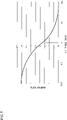
FIG. 5 shows the relationship between a braking force and a traveling velocity; -
FIG. 6A shows the relationship between a brake ratio and a duty ratio according to the first embodiment; andFIG. 6B shows the relationship between a brake ratio and a duty ratio according to the second embodiment; -
FIG. 7 illustrates the relationship between the ratio of power supply connection resistance to the resistance of a motor generator and the ratio of the amount of increase in an electric current to the amount of increase in a regenerative voltage; -
FIG. 8 shows a circuit configuration of an electric wheeled walking aid according to the third embodiment; -
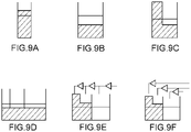
FIG. 9 shows how to store electricity in an electric storage device; -
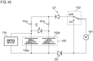
FIG. 10 shows another example of the circuit configuration of the electric wheeled walking aid according to the third embodiment; -
FIG. 11 shows a circuit configuration of an electric wheeled walking aid according to the fourth embodiment; -
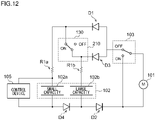
FIG. 12 shows a circuit configuration of an electric wheeled walking aid according to the fifth embodiment; and -
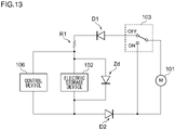
FIG. 13 shows a circuit configuration of an electric wheeled walking aid according to the sixth embodiment. - Hereinafter, an electric wheeled walking aid according to the present embodiment will be described with reference to the drawings. In the following explanation, the same reference numerals are assigned to the same configurations, and repetitive explanations will be omitted.
- In the following embodiment, as the electric wheeled walking aid, for example, a wheeled walking aid that assists the elderly in walking will be illustrated. However, as the electric wheeled walking aid, at least any wheeled walking aid vehicle whose brake is controlled by electric power can be adopted. The wheeled walking aid vehicle is driven by rotating the wheels using force input or applied by actions such as pushing by the user to the vehicle as a main driving source. Examples of such a wheeled walking aid vehicle include a wheelchair, a walker for an aged person, a stroller, and a trolley for transporting a load in addition to a wheeled walking aid.
- In the present specification, the term "brake" refers to a mechanical brake that causes a friction element such as a brake shoe to come into contact with a wheel or axle by the user's intentional operation to reduce the rotational velocity of the wheel and an electric brake that reduces the rotational velocity of the wheel by recovering the kinetic energy generated by the rotation of the wheel by electric control regardless of the user's intentional operation. The electric brake also includes a brake that rotationally drives the motor in a direction opposite to the normal driving direction to reduce the rotational speed of the wheel. Further, in the present specification, the term "electric wheeled walking aid" means a wheeled walking aid equipped with at least an electric brake. Therefore, even if an electric brake is the only element controlled by electricity in the entire wheeled walking aid, the wheeled walking aid is included as an electric wheeled walking aid.
- In the present specification, the "forward direction" means the forward direction in the normal use state of a wheeled walking aid. The "pitch angle" means an angle around an axis (pitch axis) extending in the wheeled walking aid width direction. The "roll angle" means an angle around an axis (roll axis) extending in the front-rear direction of the wheeled walking aid. The "yaw angle" means an angle around an axis (yaw axis) extending in the vertical direction of the wheeled walking aid. The "road surface inclination angle" means the inclination angle of the surface on which the wheeled walking aid is traveling. The inclination angle of the road surface is estimated to be the same as the inclination angle of the wheeled walking aid and is indicated by the angle around the pitch axis or the roll axis or by the combination of the angles around the pitch axis and the roll axis.
- As shown in
FIGS. 1 and2 , awheeled walking aid 100 includes amain body frame 11 of the body of the wheeled walking aid, a pair offront wheels 12 and a pair ofrear wheels 13 provided on themain body frame 11 of the body of the wheeled walking aid, and a support pad (body support part) 14 provided on themain body frame 11. Thewheeled walking aid 100 assists the walking of an elderly person or a person with weak leg strength. When using thewheeled walking aid 100, while putting his/her forearm or elbow on thesupport pad 14 and applying the weight (load) to thesupport pad 14, the user applies force to thewheeled walking aid 100 by pushing ahandlebar 15 while grasping thehandlebar 15 and abrake lever 16 so as to perform a walking motion. Therefore, thehandlebar 15 serves as a receiver configured to receive force from the user, and thewheeled walking aid 100 moves by the force received by the receiver. - The
main body frame 11 includes a pair ofsupport frames 21 that are inclined by a predetermined angle from a direction perpendicular to the placement surface of thewheeled walking aid 100. Thesupport frames 21 are formed using pipe-shaped members as an example. A pair oflower frames 51 are horizontally arranged on the lower end side of thesupport frames 21. A pair offront wheels 12 are attached to the front end side of thelower frames 51. A pair oflink mechanisms 55 are provided on the rear end side of thelower frames 51. - A pair of
upper frames 54 are provided above the pair oflower frames 51. One end side of a pair of rear wheel frames 57 is rotatably connected to the rear end side of theupper frames 54 via ashaft 56. A pair ofrear wheels 13 are provided on the other end side of therear wheel frame 57, respectively. - A pair of
handles 24 are provided at the respective upper ends of the pair of support frames 21. The pair ofhandles 24 are provided substantially in a horizontal manner with respect to the placement surface of thewheeled walking aid 100. The pair ofhandles 24 are formed using pipe-shaped members as an example. Each of the pair ofhandles 24 is provided with a grip 23 (seeFIG. 2 ) held by the user to stabilize the posture when the user is sitting. Further, on the front side of the pair ofhandles 24, a pipe-shapedhandlebar 15 integrated with thehandles 24 is formed. One end of thehandlebar 15 is connected to one of the pair ofhandles 24, and the other end of thehandlebar 15 is connected to theother handle 24. Thehandlebar 15 may be formed of a member different from thehandles 24. - A pair of mechanically contactable brake shoes 25 (omitted in
FIG. 1 , seeFIG. 2 ) are provided on the outer circumference of the pair ofrear wheels 13. Thebrake shoes 25 are connected to one end of a brake wire (not shown) arranged in themain body frame 11. The other end of the wire is connected to a wire connection mechanism of a pair ofbrake units 61 provided on respective sides of thehandlebar 15. Although the wire is stored in themain body frame 11, the wire may be formed such that the wire is visible to the user in appearance by arranging the wire outside the main body frame. - A
brake lever 16 is arranged in the lower front direction of thehandlebar 15 so as to face thehandlebar 15. The respective ends of thebrake lever 16 are connected to the pair ofbrake units 61. The respective ends of thebrake lever 16 are attached to thebrake units 61 via a biasing means such as a coil spring. By pulling thebrake lever 16 toward the user (in the direction of an arrow RA inFIG. 2 ), the user can apply a mechanical brake through wire action. In other words, thebrake shoes 25 are controlled by operating thebrake lever 16. - At the time of use, the user pulls the
brake lever 16 toward the user (in a direction closer to the handlebar 15) to a brake operating position. The action of the wire connected to thebrake lever 16 causes thebrake shoes 25 to move and press the outer circumference of therear wheels 13. When the user releases thebrake lever 16, thebrake lever 16 returns to the original position (normal position). Along with this, thebrake shoes 25 are also separated from therear wheels 13, and the mechanical brake is released. Further, thebrake lever 16 can be lowered in the opposite direction (lower side) of the arrow RA. By lowering thebrake lever 16 to a parking position, a state in which therear wheels 13 are being pressed by thebrake shoes 25 via the wire action is maintained. - The
support pad 14, which is a body support part, is mounted on the pair ofhandles 24. In the present embodiment, the user's forearms, elbows, or both of these are supported. - The shape of the
support pad 14 is a horseshoe shape, a U-shaped straight line shape, or the like. Thesupport pad 14 is formed by placing a cushion material such as a sponge or a rubber material on a plate material such as a wooden plate or a resin plate and covering these materials with an arbitrary covering material made of resin or cloth. Alternatively, thesupport pad 14 may be composed of only a plate material. - A pair of
arm members 26 are fixed, each at one end, to the respective lateral sides of the lower surface of thesupport pad 14. Thearm members 26 are rotatably attached, each at the other end, to the outside of the pair ofhandlebars 15, respectively. When the user pushes (strikes) thesupport pad 14 upward, thesupport pad 14 rotates in the direction of an arrow RB inFIG. 2 and is fixed at a predetermined position (retracting position) (see a virtual line inFIG. 2 ). A space for accommodating the upper body of the user is secured above aseat 37. In this state, the user can sit on theseat 37 with thesupport pad 14 on the back side while holding the pair ofgrips 23 with both hands. By holding thegrips 23, the user can stabilize his/her posture when the user is sitting. In this way, thesupport pad 14 prevents the user from sitting on theseat 37 of the wheeled walking aid at a position obtained before being pushed up (normal position) and allows the user to sit on theseat 37 of the wheeled walking aid at a position obtained after being pushed up (retracting position). - The configuration in which the user manually pushes up the
support pad 14 is shown here. However, as another example, a lock mechanism (not shown) may be provided, and thesupport pad 14 may be automatically pushed up by releasing the fixation by the lock mechanism. Alternatively, an electric mechanism (motor or the like) for rotating thearm members 26 may be provided, and thesupport pad 14 may be pushed up by operating the electric mechanism through the activation of the switch. - A storage 27 (see
FIG. 2 ) made of resin or cloth is provided so as to be suspended between the pair ofupper frames 54. Thestorage 27 has a bag shape with an upper part that is open and stores baggage. Theseat 37 for seating also functions as a lid of thestorage 27. - Behind the
storage 27, alever 28 extending downward from the pair ofupper frames 54 is provided. Thelever 28 is arranged at a position where the user can step on thelever 28 with his/her legs. When the user lowers thelever 28, thelink mechanisms 55 are folded such that the pair of rear wheel frames 57 and the pair ofrear wheels 13 approach the pair offront wheels 12, and the entirewheeled walking aid 100 is folded. - The
wheeled walking aid 100 according toFIG. 3 includes amotor generator 101, anelectric storage device 102, a switching element (hereinafter, SW element for PWM control) 103 for PWM control, asensor unit 104, and acontrol device 105. These items are housed in one housing and are integrally provided with arear wheel 13 to be controlled. In this case, a housing that houses these items may be attached to each of the pair ofrear wheels 13. - The
motor generator 101 is connected to the axle of therear wheel 13 and functions as an electric brake configured to suppress the rotational velocity of therear wheel 13. Themotor generator 101 recovers the kinetic energy generated by the rotation of therear wheel 13 and stores the kinetic energy in theelectric storage device 102. Therefore, themotor generator 101 functions as a regenerative brake or power generation brake. A servo motor, a stepping motor, a motor, a DC motor, etc., can be used as themotor generator 101. Themotor generator 101 may be connected to thefront wheel 12 or to both thefront wheel 12 and therear wheel 13. Themotor generator 101 according to the present embodiment is an example of a power generation mechanism. - The
electric storage device 102 is electrically connected to themotor generator 101 and is charged by receiving the supply of regenerative electric power generated by themotor generator 101. The regenerative electric power is generated when the user is actively moving the electric wheeled walking aid. Theelectric storage device 102 is electrically connected to thecontrol device 105 and supplies electric power to thecontrol device 105. The electric power for driving each piece of hardware is supplied from theelectric storage device 102. A battery such as a capacitor or a secondary battery such as a lithium-ion battery is used as theelectric storage device 102. Theelectric storage device 102 can be charged only with regenerative electric power or with an external power source in addition to regenerative electric power. - The
SW element 103 for PWM control is a field-effect transistor (FET) and switches the state a circuit between a short circuit and an open circuit for themotor generator 101. TheSW element 103 for PWM control is connected to a first terminal 101A and a second terminal 101B of themotor generator 101. TheSW element 103 for PWM control is controlled by thecontrol device 105. More details will follow. - The
sensor unit 104 includes one or a plurality of sensors and transmits a detection result from each sensor to thecontrol device 105. Thesensor unit 104 includes anangular velocity sensor 111 configured to detect the angular velocity of the vehicle around the pitch, roll, and yaw axes, anacceleration sensor 113 configured to detect the acceleration of the wheeled walking aid around the pitch, roll, and yaw axes, avelocity sensor 115 configured to detect the rotational velocity and rotational direction of the rear wheels, and anangle sensor 117 configured to detect the pitch angle, roll angle, and yaw angle of thewheeled walking aid 100. As theangular velocity sensor 111 and theacceleration sensor 113, a 6-axis inertial sensor in which these two sensors are combined may be used. For example, if there is no need to detect the angular velocity and acceleration around the yaw axis, a 4-axis inertial sensor capable of detecting the angular velocity and acceleration around at least the pitch and roll axes may be used. A Hall element may be used as thevelocity sensor 115, or the velocity may be calculated from back electromotive force of themotor generator 101. A magnetic field sensor may also be used instead of the acceleration sensor. The detection results from these sensors are transmitted to thecontrol device 105 as signals by a wired or wireless method. - The
sensor unit 104 may also include an inclination sensor configured to detect an inclination angle with respect to the pitch axis or the horizontal plane around the pitch axis. If it is not necessary to detect the roll angle, a sensor capable of detecting the angular velocity around the pitch axis and the acceleration in the direction of the roll axis may be used. In order to detect a pitch angle or rotation around the roll axis, only the acceleration needs to be able to be detected, and the angular velocity is not always necessary. The history or change over time of a detected value from theacceleration sensor 113 may be used to detect the inclination angle or the presence of inclination with respect to the horizontal plane, and in this case, the inclination sensor is not necessary. The detected value from theacceleration sensor 113 may be integrated to detect the velocity, and in this case, thevelocity sensor 115 is unnecessary. Also, the acceleration in the front-rear direction may be calculated by differentiating the detected value from thevelocity sensor 115 without providing theacceleration sensor 113 for detecting the acceleration in the front-rear direction. In this way, the acquisition of the velocity and the acceleration can be achieved by using either one of theacceleration sensor 113 and thevelocity sensor 115. - The
control device 105 controls a brake configured to apply braking force to the rear wheels by controlling themotor generator 101 using the regenerative electric power. Thecontrol device 105 is operated by the regenerative electric power generated in themotor generator 101 by the running of thewheeled walking aid 100. Thecontrol device 105 is connected in parallel with theelectric storage device 102. Thecontrol device 105 is formed by hardware such as a processor configured to performs arithmetic processing such as a micro processing unit (MPU), a memory configured to store information and instructions, and a temporary memory used for arithmetic operations performed by the processor. Thecontrol device 105 controls the braking force of the brake by themotor generator 101 by using the detection result obtained from each sensor. For example, thecontrol device 105 calculates the magnitude of the braking force and performs the PWM control on theSW element 103 for PWM control in order to generate the braking force, thereby controlling the braking force. - The
control device 105 includes a travelingstate estimation unit 121 and abrake control unit 123. The travelingstate estimation unit 121 estimates the traveling state of thewheeled walking aid 100. Examples of the traveling state to be estimated are shown inFIGS. 4A to 4D . As shown inFIG. 4A , the travelingstate estimation unit 121 estimates whether or not thewheeled walking aid 100 is in a state of traveling on a road (e.g., grass, gravel road, etc.) where the traveling resistance is higher than a predetermined resistance threshold (hereinafter referred to as "high resistance traveling state") based on the detection result of the acceleration in the vertical direction during the traveling from theangular velocity sensor 111. As shown inFIGS. 4B and 4C , the travelingstate estimation unit 121 estimates whether or not thewheeled walking aid 100 is in a state of traveling on an uphill street or a one-side sloped street (hereinafter referred to as "uphill traveling state" and "on-side slope traveling state", respectively) based on the detection result from theangle sensor 117. As shown inFIG. 4C , the "one-side sloped street" refers to a street that slopes in the left-right direction of the wheeled walking aid. As shown inFIG. 4D , the travelingstate estimation unit 121 estimates whether or not thewheeled walking aid 100 is in a state of traveling with a traveling velocity of a predetermined lower limit velocity (e.g., seeFIG. 5 ) or below (hereinafter referred to as "extremely low speed traveling state"). The travelingstate estimation unit 121 may capture an image of a traveling road surface and analyze the captured image so as to estimate the traveling state. - Furthermore, the
wheeled walking aid 100 ofFIG. 3 includes a power supply connection resistor R1 and first and second diodes D1 and D2. - The power supply connection resistor R1 is connected in series with the
motor generator 101 and theelectric storage device 102. In the present embodiment, the power supply connection resistor R1 is arranged between the off-side terminal of theSW element 103 for PWM control and theelectric storage device 102. The resistance value of the power supply connection resistor R1 affects the electric current supplied to themotor generator 101. For example, when the resistance value of the power supply connection resistor R1 is relatively large, a relatively small electric current flows to themotor generator 101, and when the resistance value of the power supply connection resistor R1 is relatively small, a relatively large electric current flows to themotor generator 101. Therefore, the braking force of themotor generator 101 can be adjusted by adjusting the resistance value of the power supply connection resistor R1. In the present embodiment, a resistance smaller than that of themotor generator 101 is used for the power supply connection resistor R1. For example, for a resistance of themotor generator 101 of 0.32 [Ω], the resistance of the power supply connection resistor R1 is 0.1 [Ω]. The power supply connection resistor R1 may be arranged between theelectric storage device 102 and the second terminal 101B of themotor generator 101. - The first and second diodes D1 and D2 pass an electric current in a direction from the first terminal 101A to the second terminal 101B of the
motor generator 101. The first diode D1 is arranged between the off-side terminal of theSW element 103 for PWM control and the power supply connection resistor R1. The second diode D2 is arranged between theelectric storage device 102 and the second terminal 101B of themotor generator 101. Regarding the first and second diodes D1 and D2, only one of the diodes may be used. - A control process performed by the
control device 105 will be explained in the following. The operation mainly performed by thecontrol device 105 is realized by the processor referring to instructions and information stored in the memory and executing arithmetic operations on the temporary memory. - [Brake control] As described above, the
brake control unit 123 controls the braking force of the regenerative brake applied by themotor generator 101 by PWM control of theSW element 103 for PWM control. In the PWM control, the on and off of theSW element 103 for PWM control is controlled by thebrake control unit 123. - The
brake control unit 123 outputs a control signal for controlling the on and off of theSW element 103 for PWM control to theSW element 103 for PWM control. This control signal defines the duty ratio of theSW element 103 for PWM control. The duty ratio is the percentage of the ON time of theSW element 103 for PWM control in a pulse cycle. - When the
wheeled walking aid 100 travels, themotor generator 101 rotates according to the rotation of the wheels (rear wheels 13) and generates back electromotive force in themotor generator 101. When theSW element 103 for PWM control is off, themotor generator 101 is connected to theelectric storage device 102, and theelectric storage device 102 is charged by electromotive force (regenerative electric power) generated in themotor generator 101. On the other hand, when theSW element 103 for PWM control is on, themotor generator 101 is short-circuited. When themotor generator 101 is short-circuited, an electric current proportional to the electromotive force and inversely proportional to the resistance of themotor generator 101 flows through themotor generator 101, and a braking torque proportional to the electric current is thus generated. Therefore, the larger the duty ratio, the larger the electric current supplied to themotor generator 101, thus increasing the braking torque. Since the braking torque is an average of braking torques weighted by respective duty ratios in the on state and in the off state, the breaking torque increases as the duty ratio increases. - As shown in
FIG. 5 , when the traveling velocity of thewheeled walking aid 100 is larger than a predetermined upper limit velocity, thebrake control unit 123 activates a first regenerative brake to suppress the traveling velocity such that the traveling velocity becomes a predetermined traveling velocity. This allows for traveling at a constant velocity. In this case, thebrake control unit 123 acquires the detected value from thevelocity sensor 115 and monitors the detected value. When the first regenerative brake is activated, for example, themotor generator 101 generates a braking force so as to suppress the rotational velocity of therear wheels 13. This suppresses the velocity of thewheeled walking aid 100, enhancing safety. - When the traveling velocity of the
wheeled walking aid 100 is the predetermined upper limit velocity or less, thebrake control unit 123 activates a second regenerative brake, which has a smaller braking force than that of the first regenerative brake. Thereby, a regenerative brake is always activated, and theelectric storage device 102 is always charged. Therefore, insufficient charging of theelectric storage device 102 is easily solved. In the second regenerative brake, it is preferable to maintain a weak constant braking force that can be ignored by the user. - The
brake control unit 123 determines the duty ratio at predetermined time intervals so as to output a predetermined braking torque according to the traveling velocity. However, even when the duty ratio is determined, the voltage supplied to themotor generator 101 fluctuates according to the traveling velocity, the voltage of theelectric storage device 102, and the like, and the braking force is thus caused to fluctuate. Therefore, in the present embodiment, the duty ratio for the PWM control is set based on the traveling velocity and the voltage of theelectric storage device 102. This allows the pulsation of the braking force to be reduced and thus allows discomfort during use to be reduced. - For example, the
brake control unit 123 reduces the duty ratio if the amount of decrease in the voltage of theelectric storage device 102 per a predetermined time becomes larger than a first threshold when the traveling velocity is within a predetermined velocity range. Thereby, the fluctuation of the braking force due to a decrease in the voltage of theelectric storage device 102 is suppressed. - Further, the
brake control unit 123 increases the duty ratio if the amount of increase in the voltage of theelectric storage device 102 per a predetermined time becomes larger than a second threshold when the traveling velocity is within the predetermined velocity range. Thereby, the fluctuation of the braking force due to an increase in the voltage of theelectric storage device 102 is suppressed. - The first and second thresholds are determined as appropriate according to the design, and the optimum values thereof are determined through experiment or the like.
- The
brake control unit 123 obtains a duty ratio p by the following method. First, thebrake control unit 123 determines a target braking torque T according to the traveling velocity based on a numerical value table of braking torques for traveling velocities prepared in advance. - The braking torque T is expressed by the following equation (1), as shown in the relationship between the duty ratio p and the braking torque T in
FIG. 6A .
- In Equation (1), A and B represent values larger than 0. A increases as a torque constant of the
motor generator 101 and the voltage across the terminals of theelectric storage device 102 increase, and A decreases as the impedance of themotor generator 101 increases. Further, B increases as the torque constant of themotor generator 101 and the voltage across the terminals of theelectric storage device 102 increase, and B decreases as the traveling velocity and the impedance of themotor generator 101 increase. - When Equation (1) is rearranged with respect to the duty ratio p, the duty ratio p is expressed by the following Equation (2).

- Based on Equation (2), the
brake control unit 123 can obtain the duty ratio p required to produce a specific braking torque T. - As shown in
FIG. 6A , the braking torque T is zero or less when the value of the duty ratio is a certain value (referred to as "torque generation duty ratio") or less. However, due to the action of the first and second diodes D1 and D2, the braking torque T does not actually become negative. When the torque generation duty ratio is exceeded, the braking torque T increases in a linear manner. Therefore, the duty ratio p needs to be larger than the torque generation duty ratio in order for the braking force to act. The torque generation duty ratio is obtained from p = B / A by substituting zero for T in Equation (2). - If the duty ratio is lowered too much, the braking force may become too small to provide sufficient regenerative electric power, and the
control device 105 may not be able to operate. Therefore, in the present embodiment, the lower limit of the duty ratio is set such that a regenerative voltage larger than a voltage at which thecontrol device 105 operates can be generated. This allows the control to be maintained regardless of the power storage amount of theelectric storage device 102. - The
brake control unit 123 may reduce the braking force of the second regenerative brake based on the estimation result from the travelingstate estimation unit 121. For example, by reducing the braking force of the second regenerative brake according to an estimation result indicating that the traveling state corresponds to at least one of the high resistance traveling state, the uphill traveling state, the one-side slope traveling state, and the extremely low speed traveling state shown inFIGS. 4A to 4D , thebrake control unit 123 may prevent the second regenerative brake from becoming activated. By reducing the braking force of the second regenerative brake in the high resistance traveling state and the uphill traveling state, the deterioration of driving performance is suppressed. By reducing the braking force of the second regenerative brake in the one-side slope traveling state, snaking toward the down-slope direction is suppressed, and the deterioration of traveling stability is suppressed. By reducing the braking force of the second regenerative brake in the extremely low speed traveling state, the overall power consumption of thewheeled walking aid 100 is suppressed from becoming larger than the amount of regenerative electric power obtained by the second regenerative brake. - According to the present embodiment, since the brakes are controlled by regenerative electric power, a failure of the
wheeled walking aid 100 in proper operation during use is suppressed. Further, it is no longer necessary to, for example, connect thewheeled walking aid 100 to an external power source to charge the battery. - In the present embodiment, the first regenerative brake is activated such that the traveling velocity is constant in a given case. However, this is non-limiting, and a mechanical brake may be activated such that the traveling velocity is constant.
- In the present embodiment, PWM control is performed based on the above Equations (1) to (5). However, this is non-limiting, and the PWM control may be performed based on a numerical value table for duty ratios for the current traveling velocity. In this numerical value table, for example, a duty ratio for achieving the braking force such as those shown in
FIG. 5 is set for each traveling velocity. - The braking force may be adjusted based on the inclination angle of the ground measured using a 6-axis inertial sensor or the like. A Hall element may be provided in the
motor generator 101, and the braking force may be adjusted based on the traveling velocity and the acceleration measured using the Hall element. The back electromotive force generated by themotor generator 101 may be measured using a voltage sensor or the like, and the braking force may be adjusted based on the traveling velocity and the acceleration measured using the measured back electromotive force. - In the figures and explanations of the second embodiment, the same or equivalent constituting elements and members as those in the first embodiment shall be denoted by the same reference numerals. Explanations that are the same as those in the first embodiment are appropriately omitted, and an explanation will be given focusing on features that are different from those of the first embodiment.
- In the first embodiment, as shown in
FIG. 6A , the braking torque is almost zero when the duty ratio is the torque generation duty ratio or less and rapidly increases when the duty ratio exceeds the torque generation duty ratio. Since the torque generation duty ratio depends on the traveling velocity and the voltage of theelectric storage device 102, the calculation of the duty ratio is relatively complex. Also, there is a concern that if the traveling velocity and the voltage of theelectric storage device 102 change even a little bit, the braking force would change with the change in the torque generation duty ratio, causing some loss of smoothness in traveling. - The resistance of the power supply connection resistor R1 according to the present embodiment is larger than the resistance of the
motor generator 101. For example, for a resistance of themotor generator 101 of 0.32 [Ω], the resistance of the power supply connection resistor R1 is 10 [Ω]. As a result, fluctuation in the torque generation duty ratio due to fluctuation in the voltage of theelectric storage device 102 or in the traveling resistance is negligibly small. -
FIG. 6B shows the relationship between the duty ratio and braking torque in the present embodiment. As shown inFIG. 6B , the torque generation duty ratio in the present embodiment is close to zero. Further, the braking torque increases linearly with respect to the duty ratio. - Since the torque generation duty ratio is close to zero and is thus negligible, if B/A in Equation (2) is set to zero, the
brake control unit 123 according to the present embodiment sets the duty ratio based on the following Equation (3).
- Using
FIG. 7 , an explanation will be given regarding the amount of increase in an electric current flowing through themotor generator 101 when the regenerative electric power fluctuates due to fluctuation in the traveling velocity based on the resistance of the power supply connection resistor R1 and the resistance of themotor generator 101. The smaller this amount of increase is, the higher the robustness of the braking force with respect to the fluctuation in the traveling velocity is. InFIG. 7 , the horizontal axis shows the ratio of the resistance of the power supply connection resistor R1 to the resistance of the motor generator 101 (resistance ratio), and the vertical axis shows the ratio of the amount of increase (increase ratio) in an electric current flowing through themotor generator 101 to the amount of increase in the regenerative voltage (increase ratio). InFIG. 7 , the duty ratio p is adjusted such that an electric current of 0.1 [A] flows through themotor generator 101 under a condition that the regenerative voltage is 2.5 [V], the voltage of theelectric storage device 102 is 5 [V], the voltage across the terminals (voltage drop) due to the first diode D1 is 0.6 [V], and the resistance ofmotor generator 101 is 0.32 [Ω]. - In the first embodiment, the resistance ratio is 0.3125 since the resistance of the power supply connection resistor R1 is 0.1 [Ω] and the resistance of the
motor generator 101 is 0.32 [Ω]. Therefore, as shown inFIG. 7 , the increase ratio in the first embodiment is around 3 to 3.5. On the other hand, the resistance ratio in the present embodiment is about 31.25. Therefore, as shown inFIG. 7 , the increase ratio in the present embodiment is around 0.1 to 0.3. Therefore, in the present embodiment, the robustness of the braking force with respect to the fluctuation in the traveling velocity is higher than that in the first embodiment. - According to the present embodiment, the braking force is less likely to be affected by the fluctuation in the torque generation duty ratio, and the duty ratio can be calculated with a relatively small calculation load. As a result, the fluctuation in the braking force is suppressed. Therefore, the smoothness in traveling is further increased.
- In the figures and explanations of the third embodiment, the same or equivalent constituting elements and members as those in the first embodiment shall be denoted by the same reference numerals. Explanations that are the same as those in the first embodiment are appropriately omitted, and an explanation will be given focusing on features that are different from those of the first embodiment. In
FIG. 8 below, thesensor unit 104 is omitted for the sake of simplification. In the same way, thesensor unit 104 is omitted inFIGS. 10 to 13 described later. - As shown in
FIG. 8 , anelectric storage device 102 in the present embodiment includes a firstelectric storage unit 102a and a secondelectric storage unit 102b having a larger capacity than the firstelectric storage unit 102a. The firstelectric storage unit 102a and the secondelectric storage unit 102b are connected in parallel. A first power supply connection resistor R1a is connected to the firstelectric storage unit 102a, and a second power supply connection resistor R1b is connected to the secondelectric storage unit 102b. The resistance of the second power supply connection resistor R1b is larger than that of the first power supply connection resistor R1a. The firstelectric storage unit 102a and the secondelectric storage unit 102b according to the present embodiment are capacitors. - As shown in
FIG. 9A , since the capacity of the firstelectric storage unit 102a is relatively small, when regenerative electric power is supplied, the voltage of the firstelectric storage unit 102a quickly rises to the operating voltage of thecontrol device 105. However, the power storage amount is small. Further, the braking torque tends to fluctuate when the traveling velocity fluctuates. - On the other hand, as shown in
FIG. 9B , since the capacity of the secondelectric storage unit 102b is relatively large, the power storage amount is large. However, even when regenerative electric power is supplied, it takes time until the voltage of the secondelectric storage unit 102b rises to the operating voltage of thecontrol device 105 so as to cause thecontrol device 105 to operate. - In the present embodiment, the first
electric storage unit 102a and the secondelectric storage unit 102b configured to have different capacities are connected in parallel. As shown inFIG. 9C , when regenerative electric power is supplied, although both the firstelectric storage unit 102a and the secondelectric storage unit 102b are charged, the voltage of the firstelectric storage unit 102a having a relatively small capacity reaches the operating voltage of the control device first. As a result, the operating voltage of thecontrol device 105 is obtained early. In addition, since the secondelectric storage unit 102b having a relatively large capacity is charged even after the voltage of the firstelectric storage unit 102a reaches the operating voltage of thecontrol device 105, a sufficient power storage amount can be obtained. - As might be expected, the
electric storage device 102 may include three or more electric storage units that are connected in parallel and each have a different capacity. As shown inFIG. 10 , a diode D' may be arranged between the terminal located between the firstelectric storage unit 102a and the first power supply connection resistor R1a and the terminal located between the secondelectric storage unit 102b and the second power supply connection resistor R1b. - In the figures and explanations of the fourth embodiment, the same or equivalent constituting elements and members as those in the third embodiment shall be denoted by the same reference numerals. Explanations that are the same as those in the third embodiment are appropriately omitted, and an explanation will be given focusing on features that are different from those of the third embodiment.
- As shown in
FIG. 11 , awheeled walking aid 100 according to the present embodiment includes third and fourth diodes D3 and D4 connected to a firstelectric storage unit 102a and a secondelectric storage unit 102b, respectively. In the present embodiment, the first and third diodes D1 and D3 are connected in series, and the second and fourth diodes D2 and D4 are connected in series. The first through fourth diodes D1-D4 pass an electric current in a direction from the first terminal 101A to the second terminal 101B of themotor generator 101. - When the electromotive force from the regeneration runs out, there are cases when an electric current flows back from the first
electric storage unit 102a to the secondelectric storage unit 102b and the power storage amount is smoothed between the firstelectric storage unit 102a and the secondelectric storage unit 102b as shown inFIG. 9D . In this case, it takes time for the voltage of theelectric storage device 102 to reach the operating voltage of thecontrol device 105. - According to this configuration, since the first and third diodes D1 and D3 are connected in series, the backflow of an electric current from the first
electric storage unit 102a to the secondelectric storage unit 102b is suppressed. As a result, as shown inFIG. 9E , the smoothing of the power storage amount between the firstelectric storage unit 102a and the secondelectric storage unit 102b is suppressed. - In the figures and explanations of the fifth embodiment, the same or equivalent constituting elements and members as those in the fourth embodiment shall be denoted by the same reference numerals. Explanations that are the same as those in the fourth embodiment are appropriately omitted, and an explanation will be given focusing on features that are different from those of the fourth embodiment.
- As shown in
FIG. 12 , in the present embodiment, the first and third diodes D1 and D3 are connected in parallel. Further, between the cathode side terminals of the first and third diodes D1 and D3, anSW element 130 for electric storage control is electrically connected. As theSW element 130 for electric storage control, a field effect transistor (FET) is used. - When the first and third diodes D1 and D3 are connected in series, a voltage drop due to the first and third diodes D1 and D3 is large.
- In contrast, according to the present embodiment, the voltage drop due to the first and third diodes D1 and D3 is suppressed.
- An explanation will be given regarding the control of the
SW element 130 for electric storage control. When thecontrol device 105 is not started, theSW element 130 for electric storage control is in an off state. In the off state, the first diode D1, the first power supply connection resistor R1a, and the firstelectric storage unit 102a are connected in parallel to the second diode D2, the second power supply connection resistor R1b, and the secondelectric storage unit 102b. When thewheeled walking aid 100 travels generating regenerative electric power, an electric current flows to the firstelectric storage unit 102a from themotor generator 101 via the first diode D1 and to the secondelectric storage unit 102b from themotor generator 101 via the third diode D3, separately. The voltage in the firstelectric storage unit 102a then reaches the operating voltage of thecontrol device 105 first, and thecontrol device 105 operates. Meanwhile, the backflow of the electric current from the firstelectric storage unit 102a to the secondelectric storage unit 102b is suppressed by the first and third diodes D1 and D3. - However, when the
SW element 130 for electric storage control is in the off state, while the firstelectric storage unit 102a supplies voltage to thecontrol device 105, the secondelectric storage unit 102b cannot supply voltage to thecontrol device 105 due to the action of the third diode D3. Therefore, in the off state, the power storage amount of theelectric storage device 102, which has a relatively small capacity, is substantially equal to the power storage amount of the firstelectric storage unit 102a, and only a small amount of power storage can be obtained. - In order to avoid this, after finishing operation, the
control device 105 switches on theSW element 130 for electric storage control. Thereby, the first and second diodes D1 and D2 do not become connected in parallel, and the first power supply connection resistor R1a and the firstelectric storage unit 102a become connected in parallel to the second power supply connection resistor R1b and the secondelectric storage unit 102b. As a result, the composite voltage of the firstelectric storage unit 102a and the secondelectric storage unit 102b is supplied to thecontrol device 105. Therefore, in an on state, since the power storage amount of the electric storage device is the sum of the power storage amount of the firstelectric storage unit 102a and the power storage amount of the secondelectric storage unit 102b, a large power storage amount can be obtained. - In the figures and explanations of the sixth embodiment, the same or equivalent constituting elements and members as those in the first embodiment shall be denoted by the same reference numerals. Explanations that are the same as those in the first embodiment are appropriately omitted, and an explanation will be given focusing on features that are different from those of the first embodiment.
- As shown in
FIG. 13 , awheeled walking aid 100 according to the present embodiment includes a Zener diode Zd connected in parallel to theelectric storage device 102. According to the present configuration, when the power storage amount of theelectric storage device 102 increases sufficiently such that it is difficult for an electric current to flow through theelectric storage device 102, the electric current is bypassed via the Zener diode Zd. Therefore, since the loss of an electric current flow to themotor generator 101 is suppressed, the loss of a braking force is suppressed, and theelectric storage device 102 is prevented from failing due to voltage in excess of the withstand voltage. - The present invention relates to electric wheeled walking aids.
-
main body frame 11,front wheel 12, rear wheel - 13,
support pad 14,handlebar 15,brake lever 16,support frame 21,grip 23, handle 24,brake shoe 25,arm member 26,storage 27,lever 28,seat 37,lower frame 51,upper frame 54,link mechanism 55,shaft 56,rear wheel frame 57,brake unit 61, wheeled walking aid - 100,
motor generator 101, first terminal 101A, second terminal 101B,electric storage device 102, firstelectric storage unit 102a, second electric storage unit - 102b, SW element for
PWM control 103, sensor unit - 104,
control device 105, power supply connection resistor R1,angular velocity sensor 111,acceleration sensor 113,velocity sensor 115,angle sensor 117, travelingstate estimation unit 121, brake control unit - 123, SW element for
electric storage control 130
Claims (15)
- An electric wheeled walking aid comprising:wheels provided on a body of the electric wheeled walking aid;a power generation mechanism configured to generate regenerative electric power in accordance with the rotation of the wheels; anda control device configured to control a brake that applies braking force to the wheels using the regenerative electric power generated by the power generation mechanism.
- The electric wheeled walking aid according to claim 1, wherein the regenerative electric power is generated when a user is actively moving the electric wheeled walking aid.
- The electric wheeled walking aid according to claim 1 or 2, wherein the control device always activates a regenerative brake applied by the power generation mechanism.
- The electric wheeled walking aid according to any one of claims 1 through 3, wherein the control device includes a traveling state estimation unit configured to estimate the traveling state of the electric wheeled walking aid, wherein the control device activates a regenerative brake applied by the power generation mechanism based on an estimation result from the traveling state estimation unit.
- The electric wheeled walking aid according to claim 4, wherein the control device reduces the braking force of the regenerative brake according to an estimation result from the traveling state estimation unit indicating that the traveling state corresponds to at least one of a high resistance traveling state, an uphill traveling state, a one-side slope traveling state, and an extremely low speed traveling state.
- The electric wheeled walking aid according to any one of claims 1 through 4, comprising an electric storage device configured to store the regenerative electric power.
- The electric wheeled walking aid according to claim 6, comprising:a switching element configured to be able to can adjust voltage to be supplied to the power generation mechanism by PWM control; anda power supply connection resistor electrically connected in series between the power generation mechanism and the electric storage device and whose resistance is larger than the resistance of the power generation mechanism, whereinthe control device sets the duty ratio of the PWM control based on the traveling velocity of the electric wheeled walking aid.
- The electric wheeled walking aid according to claim 7, comprising a Zener diode connected in parallel to the electric storage device.
- The electric wheeled walking aid according to claim 6, comprising:a switching element unit configured to be able to adjust voltage supplied to the power generation mechanism by PWM control, whereinthe control device sets the duty ratio of the PWM control based on the traveling velocity of the electric wheeled walking aid and the voltage of the electric storage device.
- The electric wheeled walking aid according to claim 9, wherein the control device reduces the duty ratio if the amount of decrease in the voltage of the electric storage device becomes larger than a first threshold when the traveling velocity is within a predetermined velocity range.
- The electric wheeled walking aid according to claim 9 or 10, wherein the lower limit of the duty ratio is set such that a regenerative voltage larger than a voltage at which the control device operates can be generated in the power generation mechanism.
- The electric wheeled walking aid according to any one of claims 9 through 11, wherein the control device increases the duty ratio if the amount of increase in the voltage of the electric storage device becomes larger than a second threshold when the traveling velocity is within a predetermined velocity range.
- The electric wheeled walking aid according to claim 6, wherein the electric storage device includes a plurality of electric storage units of different capacities that are connected in parallel.
- The electric wheeled walking aid according to claim 13, comprising a plurality of diodes connected respectively to the plurality of electric storage units such that a backflow of an electric current from the electric storage units is suppressed.
- The electric wheeled walking aid according to claim 14, wherein the plurality of diodes are connected in parallel.
Applications Claiming Priority (2)
| Application Number | Priority Date | Filing Date | Title |
|---|---|---|---|
| JP2019235314 | 2019-12-25 | ||
| PCT/JP2020/047867 WO2021132216A1 (en) | 2019-12-25 | 2020-12-22 | Electric wheeled walking aid |
Publications (2)
| Publication Number | Publication Date |
|---|---|
| EP4082508A1 true EP4082508A1 (en) | 2022-11-02 |
| EP4082508A4 EP4082508A4 (en) | 2024-01-24 |
Family
ID=76574139
Family Applications (1)
| Application Number | Title | Priority Date | Filing Date |
|---|---|---|---|
| EP20905070.7A Pending EP4082508A4 (en) | 2019-12-25 | 2020-12-22 | Electric wheeled walking aid |
Country Status (4)
| Country | Link |
|---|---|
| EP (1) | EP4082508A4 (en) |
| JP (1) | JP7220810B2 (en) |
| CN (1) | CN114867444A (en) |
| WO (1) | WO2021132216A1 (en) |
Family Cites Families (12)
| Publication number | Priority date | Publication date | Assignee | Title |
|---|---|---|---|---|
| JPH08280763A (en) | 1995-04-10 | 1996-10-29 | Isao Ueda | Motor-driven type four-wheel handcart as cane |
| JPH11267162A (en) | 1998-03-19 | 1999-10-05 | Eiji Matsuura | Walk assisting cart |
| JP2001104418A (en) * | 1999-10-04 | 2001-04-17 | Nabco Ltd | Braking device for walking cart |
| JP2002166456A (en) * | 2000-12-04 | 2002-06-11 | Tokimec Inc | Horizontal molding machine |
| JP2004216997A (en) * | 2003-01-10 | 2004-08-05 | Nissan Motor Co Ltd | Brake control device of vehicle |
| JP2009183407A (en) | 2008-02-05 | 2009-08-20 | Toyota Motor Corp | Walking aid device |
| JP5268479B2 (en) * | 2008-07-31 | 2013-08-21 | パナソニック株式会社 | Electric assist bicycle |
| JP5704285B2 (en) * | 2012-09-18 | 2015-04-22 | 株式会社村田製作所 | Wheelbarrow |
| WO2014188726A1 (en) * | 2013-05-22 | 2014-11-27 | ナブテスコ株式会社 | Electric walking assistance device, program for controlling electric walking assistance device, and method of controlling electric walking assistance device |
| JP6308611B2 (en) * | 2013-08-06 | 2018-04-11 | 学校法人 東洋大学 | Auxiliary walking vehicle with kick detection |
| KR101929535B1 (en) * | 2016-11-24 | 2018-12-14 | 조선대학교산학협력단 | motor dirving apparatus of electric silver car |
| CN109199802B (en) * | 2017-06-29 | 2021-04-06 | 沈阳新松机器人自动化股份有限公司 | Auxiliary walking vehicle and control method thereof |
-
2020
- 2020-12-22 WO PCT/JP2020/047867 patent/WO2021132216A1/en active Application Filing
- 2020-12-22 EP EP20905070.7A patent/EP4082508A4/en active Pending
- 2020-12-22 CN CN202080090233.9A patent/CN114867444A/en active Pending
- 2020-12-22 JP JP2021567477A patent/JP7220810B2/en active Active
Also Published As
| Publication number | Publication date |
|---|---|
| CN114867444A (en) | 2022-08-05 |
| WO2021132216A1 (en) | 2021-07-01 |
| JPWO2021132216A1 (en) | 2021-07-01 |
| EP4082508A4 (en) | 2024-01-24 |
| JP7220810B2 (en) | 2023-02-10 |
Similar Documents
| Publication | Publication Date | Title |
|---|---|---|
| US8881852B2 (en) | Pushable frame with generators that convert kinetic energy into electric energy | |
| US20150066325A1 (en) | Mobile object | |
| CN105078672B (en) | A kind of self-balancing electric wheel chair | |
| EP1886913B1 (en) | Electrically assisted bicycle | |
| CN210872841U (en) | Old and weak patient is with hand formula of intelligence walking aid car | |
| EP3360769B1 (en) | Electric bicycle and method of controlling the same | |
| EP3153147A1 (en) | Electric vehicle and control method thereof | |
| JP3054234B2 (en) | Bicycle with electric motor | |
| WO2023272773A1 (en) | Power-assisted control method and apparatus for smart walking aid, smart walking aid, and controller | |
| CN109199802B (en) | Auxiliary walking vehicle and control method thereof | |
| CN110037865B (en) | Novel electric nursing wheelchair and control method thereof | |
| JP6794099B2 (en) | Power-assisted vehicles, control methods, and programs | |
| EP4082508A1 (en) | Electric wheeled walking aid | |
| EP3308761B1 (en) | Electric vehicle and method of breaking the same | |
| EP4082507A1 (en) | Electrically controlled vehicle | |
| JP2015040015A (en) | Bicycle with electric motor | |
| Hou et al. | Design and implementation of a novel power assisted drivetrain for a wheelchair | |
| KR101515086B1 (en) | Walking supporter using electric power | |
| EP4082509A1 (en) | Electric braking mechanism-equipped vehicle, wheel unit, and control program for wheel unit | |
| KR100902252B1 (en) | Apparatus for break of walking support machine | |
| JP7479146B2 (en) | Electrically Controlled Vehicles | |
| JP4636662B2 (en) | Electric wheelchair | |
| KR101929535B1 (en) | motor dirving apparatus of electric silver car | |
| JP3214709U (en) | Assist bicycle | |
| WO2015198617A1 (en) | Walking assistance device |
Legal Events
| Date | Code | Title | Description |
|---|---|---|---|
| STAA | Information on the status of an ep patent application or granted ep patent |
Free format text: STATUS: THE INTERNATIONAL PUBLICATION HAS BEEN MADE |
|
| PUAI | Public reference made under article 153(3) epc to a published international application that has entered the european phase |
Free format text: ORIGINAL CODE: 0009012 |
|
| STAA | Information on the status of an ep patent application or granted ep patent |
Free format text: STATUS: REQUEST FOR EXAMINATION WAS MADE |
|
| 17P | Request for examination filed |
Effective date: 20220722 |
|
| AK | Designated contracting states |
Kind code of ref document: A1 Designated state(s): AL AT BE BG CH CY CZ DE DK EE ES FI FR GB GR HR HU IE IS IT LI LT LU LV MC MK MT NL NO PL PT RO RS SE SI SK SM TR |
|
| DAV | Request for validation of the european patent (deleted) | ||
| DAX | Request for extension of the european patent (deleted) | ||
| P01 | Opt-out of the competence of the unified patent court (upc) registered |
Effective date: 20230523 |
|
| A4 | Supplementary search report drawn up and despatched |
Effective date: 20240103 |
|
| RIC1 | Information provided on ipc code assigned before grant |
Ipc: B60L 15/20 20060101ALI20231220BHEP Ipc: B60L 7/10 20060101ALI20231220BHEP Ipc: A61G 5/10 20060101ALI20231220BHEP Ipc: A61G 5/04 20130101ALI20231220BHEP Ipc: A61H 3/04 20060101AFI20231220BHEP |