EP4082449B1 - Asymmetrischer externer träger zur stabilisierung eines venentransplantats zur verwendung in einem koronararterienbypasstransplantat (cabg) - Google Patents
Asymmetrischer externer träger zur stabilisierung eines venentransplantats zur verwendung in einem koronararterienbypasstransplantat (cabg) Download PDFInfo
- Publication number
- EP4082449B1 EP4082449B1 EP22168977.1A EP22168977A EP4082449B1 EP 4082449 B1 EP4082449 B1 EP 4082449B1 EP 22168977 A EP22168977 A EP 22168977A EP 4082449 B1 EP4082449 B1 EP 4082449B1
- Authority
- EP
- European Patent Office
- Prior art keywords
- dep
- wire
- loop
- pair
- distal end
- Prior art date
- Legal status (The legal status is an assumption and is not a legal conclusion. Google has not performed a legal analysis and makes no representation as to the accuracy of the status listed.)
- Active
Links
Images





Classifications
-
- A—HUMAN NECESSITIES
- A61—MEDICAL OR VETERINARY SCIENCE; HYGIENE
- A61F—FILTERS IMPLANTABLE INTO BLOOD VESSELS; PROSTHESES; DEVICES PROVIDING PATENCY TO, OR PREVENTING COLLAPSING OF, TUBULAR STRUCTURES OF THE BODY, e.g. STENTS; ORTHOPAEDIC, NURSING OR CONTRACEPTIVE DEVICES; FOMENTATION; TREATMENT OR PROTECTION OF EYES OR EARS; BANDAGES, DRESSINGS OR ABSORBENT PADS; FIRST-AID KITS
- A61F2/00—Filters implantable into blood vessels; Prostheses, i.e. artificial substitutes or replacements for parts of the body; Appliances for connecting them with the body; Devices providing patency to, or preventing collapsing of, tubular structures of the body, e.g. stents
- A61F2/82—Devices providing patency to, or preventing collapsing of, tubular structures of the body, e.g. stents
- A61F2/86—Stents in a form characterised by the wire-like elements; Stents in the form characterised by a net-like or mesh-like structure
-
- A—HUMAN NECESSITIES
- A61—MEDICAL OR VETERINARY SCIENCE; HYGIENE
- A61F—FILTERS IMPLANTABLE INTO BLOOD VESSELS; PROSTHESES; DEVICES PROVIDING PATENCY TO, OR PREVENTING COLLAPSING OF, TUBULAR STRUCTURES OF THE BODY, e.g. STENTS; ORTHOPAEDIC, NURSING OR CONTRACEPTIVE DEVICES; FOMENTATION; TREATMENT OR PROTECTION OF EYES OR EARS; BANDAGES, DRESSINGS OR ABSORBENT PADS; FIRST-AID KITS
- A61F2/00—Filters implantable into blood vessels; Prostheses, i.e. artificial substitutes or replacements for parts of the body; Appliances for connecting them with the body; Devices providing patency to, or preventing collapsing of, tubular structures of the body, e.g. stents
- A61F2/02—Prostheses implantable into the body
- A61F2/04—Hollow or tubular parts of organs, e.g. bladders, tracheae, bronchi or bile ducts
- A61F2/06—Blood vessels
- A61F2/064—Blood vessels with special features to facilitate anastomotic coupling
-
- A—HUMAN NECESSITIES
- A61—MEDICAL OR VETERINARY SCIENCE; HYGIENE
- A61F—FILTERS IMPLANTABLE INTO BLOOD VESSELS; PROSTHESES; DEVICES PROVIDING PATENCY TO, OR PREVENTING COLLAPSING OF, TUBULAR STRUCTURES OF THE BODY, e.g. STENTS; ORTHOPAEDIC, NURSING OR CONTRACEPTIVE DEVICES; FOMENTATION; TREATMENT OR PROTECTION OF EYES OR EARS; BANDAGES, DRESSINGS OR ABSORBENT PADS; FIRST-AID KITS
- A61F2/00—Filters implantable into blood vessels; Prostheses, i.e. artificial substitutes or replacements for parts of the body; Appliances for connecting them with the body; Devices providing patency to, or preventing collapsing of, tubular structures of the body, e.g. stents
- A61F2/82—Devices providing patency to, or preventing collapsing of, tubular structures of the body, e.g. stents
- A61F2/86—Stents in a form characterised by the wire-like elements; Stents in the form characterised by a net-like or mesh-like structure
- A61F2/90—Stents in a form characterised by the wire-like elements; Stents in the form characterised by a net-like or mesh-like structure characterised by a net-like or mesh-like structure
-
- A—HUMAN NECESSITIES
- A61—MEDICAL OR VETERINARY SCIENCE; HYGIENE
- A61F—FILTERS IMPLANTABLE INTO BLOOD VESSELS; PROSTHESES; DEVICES PROVIDING PATENCY TO, OR PREVENTING COLLAPSING OF, TUBULAR STRUCTURES OF THE BODY, e.g. STENTS; ORTHOPAEDIC, NURSING OR CONTRACEPTIVE DEVICES; FOMENTATION; TREATMENT OR PROTECTION OF EYES OR EARS; BANDAGES, DRESSINGS OR ABSORBENT PADS; FIRST-AID KITS
- A61F2/00—Filters implantable into blood vessels; Prostheses, i.e. artificial substitutes or replacements for parts of the body; Appliances for connecting them with the body; Devices providing patency to, or preventing collapsing of, tubular structures of the body, e.g. stents
- A61F2/02—Prostheses implantable into the body
- A61F2/04—Hollow or tubular parts of organs, e.g. bladders, tracheae, bronchi or bile ducts
- A61F2/06—Blood vessels
- A61F2/07—Stent-grafts
-
- A—HUMAN NECESSITIES
- A61—MEDICAL OR VETERINARY SCIENCE; HYGIENE
- A61B—DIAGNOSIS; SURGERY; IDENTIFICATION
- A61B17/00—Surgical instruments, devices or methods
- A61B2017/00831—Material properties
- A61B2017/00862—Material properties elastic or resilient
-
- A—HUMAN NECESSITIES
- A61—MEDICAL OR VETERINARY SCIENCE; HYGIENE
- A61B—DIAGNOSIS; SURGERY; IDENTIFICATION
- A61B17/00—Surgical instruments, devices or methods
- A61B17/11—Surgical instruments, devices or methods for performing anastomosis; Buttons for anastomosis
- A61B2017/1107—Surgical instruments, devices or methods for performing anastomosis; Buttons for anastomosis for blood vessels
-
- A—HUMAN NECESSITIES
- A61—MEDICAL OR VETERINARY SCIENCE; HYGIENE
- A61B—DIAGNOSIS; SURGERY; IDENTIFICATION
- A61B17/00—Surgical instruments, devices or methods
- A61B17/11—Surgical instruments, devices or methods for performing anastomosis; Buttons for anastomosis
- A61B2017/1132—End-to-end connections
-
- A—HUMAN NECESSITIES
- A61—MEDICAL OR VETERINARY SCIENCE; HYGIENE
- A61F—FILTERS IMPLANTABLE INTO BLOOD VESSELS; PROSTHESES; DEVICES PROVIDING PATENCY TO, OR PREVENTING COLLAPSING OF, TUBULAR STRUCTURES OF THE BODY, e.g. STENTS; ORTHOPAEDIC, NURSING OR CONTRACEPTIVE DEVICES; FOMENTATION; TREATMENT OR PROTECTION OF EYES OR EARS; BANDAGES, DRESSINGS OR ABSORBENT PADS; FIRST-AID KITS
- A61F2/00—Filters implantable into blood vessels; Prostheses, i.e. artificial substitutes or replacements for parts of the body; Appliances for connecting them with the body; Devices providing patency to, or preventing collapsing of, tubular structures of the body, e.g. stents
- A61F2/02—Prostheses implantable into the body
- A61F2/04—Hollow or tubular parts of organs, e.g. bladders, tracheae, bronchi or bile ducts
- A61F2/06—Blood vessels
- A61F2/07—Stent-grafts
- A61F2002/075—Stent-grafts the stent being loosely attached to the graft material, e.g. by stitching
-
- A—HUMAN NECESSITIES
- A61—MEDICAL OR VETERINARY SCIENCE; HYGIENE
- A61F—FILTERS IMPLANTABLE INTO BLOOD VESSELS; PROSTHESES; DEVICES PROVIDING PATENCY TO, OR PREVENTING COLLAPSING OF, TUBULAR STRUCTURES OF THE BODY, e.g. STENTS; ORTHOPAEDIC, NURSING OR CONTRACEPTIVE DEVICES; FOMENTATION; TREATMENT OR PROTECTION OF EYES OR EARS; BANDAGES, DRESSINGS OR ABSORBENT PADS; FIRST-AID KITS
- A61F2/00—Filters implantable into blood vessels; Prostheses, i.e. artificial substitutes or replacements for parts of the body; Appliances for connecting them with the body; Devices providing patency to, or preventing collapsing of, tubular structures of the body, e.g. stents
- A61F2/82—Devices providing patency to, or preventing collapsing of, tubular structures of the body, e.g. stents
- A61F2/848—Devices providing patency to, or preventing collapsing of, tubular structures of the body, e.g. stents having means for fixation to the vessel wall, e.g. barbs
- A61F2002/8483—Barbs
-
- A—HUMAN NECESSITIES
- A61—MEDICAL OR VETERINARY SCIENCE; HYGIENE
- A61F—FILTERS IMPLANTABLE INTO BLOOD VESSELS; PROSTHESES; DEVICES PROVIDING PATENCY TO, OR PREVENTING COLLAPSING OF, TUBULAR STRUCTURES OF THE BODY, e.g. STENTS; ORTHOPAEDIC, NURSING OR CONTRACEPTIVE DEVICES; FOMENTATION; TREATMENT OR PROTECTION OF EYES OR EARS; BANDAGES, DRESSINGS OR ABSORBENT PADS; FIRST-AID KITS
- A61F2220/00—Fixations or connections for prostheses classified in groups A61F2/00 - A61F2/26 or A61F2/82 or A61F9/00 or A61F11/00 or subgroups thereof
- A61F2220/0025—Connections or couplings between prosthetic parts, e.g. between modular parts; Connecting elements
- A61F2220/005—Connections or couplings between prosthetic parts, e.g. between modular parts; Connecting elements using adhesives
-
- A—HUMAN NECESSITIES
- A61—MEDICAL OR VETERINARY SCIENCE; HYGIENE
- A61F—FILTERS IMPLANTABLE INTO BLOOD VESSELS; PROSTHESES; DEVICES PROVIDING PATENCY TO, OR PREVENTING COLLAPSING OF, TUBULAR STRUCTURES OF THE BODY, e.g. STENTS; ORTHOPAEDIC, NURSING OR CONTRACEPTIVE DEVICES; FOMENTATION; TREATMENT OR PROTECTION OF EYES OR EARS; BANDAGES, DRESSINGS OR ABSORBENT PADS; FIRST-AID KITS
- A61F2220/00—Fixations or connections for prostheses classified in groups A61F2/00 - A61F2/26 or A61F2/82 or A61F9/00 or A61F11/00 or subgroups thereof
- A61F2220/0025—Connections or couplings between prosthetic parts, e.g. between modular parts; Connecting elements
- A61F2220/0058—Connections or couplings between prosthetic parts, e.g. between modular parts; Connecting elements soldered or brazed or welded
-
- A—HUMAN NECESSITIES
- A61—MEDICAL OR VETERINARY SCIENCE; HYGIENE
- A61F—FILTERS IMPLANTABLE INTO BLOOD VESSELS; PROSTHESES; DEVICES PROVIDING PATENCY TO, OR PREVENTING COLLAPSING OF, TUBULAR STRUCTURES OF THE BODY, e.g. STENTS; ORTHOPAEDIC, NURSING OR CONTRACEPTIVE DEVICES; FOMENTATION; TREATMENT OR PROTECTION OF EYES OR EARS; BANDAGES, DRESSINGS OR ABSORBENT PADS; FIRST-AID KITS
- A61F2220/00—Fixations or connections for prostheses classified in groups A61F2/00 - A61F2/26 or A61F2/82 or A61F9/00 or A61F11/00 or subgroups thereof
- A61F2220/0025—Connections or couplings between prosthetic parts, e.g. between modular parts; Connecting elements
- A61F2220/0075—Connections or couplings between prosthetic parts, e.g. between modular parts; Connecting elements sutured, ligatured or stitched, retained or tied with a rope, string, thread, wire or cable
-
- A—HUMAN NECESSITIES
- A61—MEDICAL OR VETERINARY SCIENCE; HYGIENE
- A61F—FILTERS IMPLANTABLE INTO BLOOD VESSELS; PROSTHESES; DEVICES PROVIDING PATENCY TO, OR PREVENTING COLLAPSING OF, TUBULAR STRUCTURES OF THE BODY, e.g. STENTS; ORTHOPAEDIC, NURSING OR CONTRACEPTIVE DEVICES; FOMENTATION; TREATMENT OR PROTECTION OF EYES OR EARS; BANDAGES, DRESSINGS OR ABSORBENT PADS; FIRST-AID KITS
- A61F2250/00—Special features of prostheses classified in groups A61F2/00 - A61F2/26 or A61F2/82 or A61F9/00 or A61F11/00 or subgroups thereof
- A61F2250/0014—Special features of prostheses classified in groups A61F2/00 - A61F2/26 or A61F2/82 or A61F9/00 or A61F11/00 or subgroups thereof having different values of a given property or geometrical feature, e.g. mechanical property or material property, at different locations within the same prosthesis
- A61F2250/0018—Special features of prostheses classified in groups A61F2/00 - A61F2/26 or A61F2/82 or A61F9/00 or A61F11/00 or subgroups thereof having different values of a given property or geometrical feature, e.g. mechanical property or material property, at different locations within the same prosthesis differing in elasticity, stiffness or compressibility
Definitions
- the present invention relates to vascular implants that externally cover vein grafts used in coronary arterial bypass graft (CABG) procedures, and more particularly, to an asymmetric external support for stabilizing a vein graft used in a coronary arterial bypass graft (CABG) procedure, and applications thereof.
- CABG coronary arterial bypass graft
- SVGs autologous saphenous vein grafts
- CABG coronary arterial bypass graft
- IVUS intravascular ultrasound
- OCT optical coherence tomography
- the present invention is defined by claim 1 and it relates to vascular implants that externally cover vein grafts used in coronary arterial bypass graft (CABG) procedures, and more particularly, to an asymmetric external support for stabilizing a vein graft used in a coronary arterial bypass graft (CABG) procedure, and applications thereof.
- exemplary applications of the herein disclosed asymmetric external support are in methods for externally supporting and stabilizing a vein graft used in a coronary arterial bypass graft (CABG) procedure.
- an asymmetric external support for stabilizing a vein graft used in a coronary arterial bypass graft procedure
- the asymmetric external support comprising: a tubular wire mesh longitudinally extending proximally and distally with wire mesh proximal, middle, and distal portions, and, wire mesh proximal and distal ends, the wire mesh is configured with non-paired elastic wires and paired plastically deformable wires; the non-paired elastic wires longitudinally extend along full longitudinal length of the wire mesh, whereby proximal and distal ends of the elastic wires coincide with the wire mesh proximal and distal ends, respectively; the wire mesh proximal portion has the proximal ends of all the paired plastically deformable wires being non-connected and open; the wire mesh distal portion has the paired plastically deformable wires configured with inter-looped distal end portions, whereby each pair of the plastically deformable wires has a first wire with
- the asymmetric external support (herein, for brevity, also referred to as 'the support') for stabilizing a vein graft used in a coronary arterial bypass graft (CABG) procedure, is in the form of a tubular wire braid or mesh (herein, for brevity, also referred to as 'the wire mesh') longitudinally extending proximally and distally along the full longitudinal length of the support.
- the support (wire mesh) has a proximal portion, a middle portion, a distal portion, a proximal end, and a distal end.
- the support (wire mesh) has an outer radius, and has an outer circumferential periphery that spans along, and parallel to, the full longitudinal length of the support (wire mesh).
- Such outer circumferential periphery corresponds to the (virtual or effective) circular (tubular) surface that surrounds (encircles, encompasses, bounds) the support (wire mesh) along, and parallel to, its full longitudinal length.
- the support (wire mesh) is configured with non-paired elastic wires and paired plastically deformable wires.
- the exemplary asymmetric external support has an exemplary total number of 42 wires (or filaments), including an exemplary total number of 38 non-paired elastic wires (filaments), and an exemplary total number of 4 paired plastically deformable wires (filaments) corresponding to two pairs of two plastically deformable wires (filaments).
- the non-paired elastic wires longitudinally extend along the full longitudinal length of the support (wire mesh), whereby the proximal ends of the elastic wires coincide with the support (wire mesh) proximal end, and the distal ends of the elastic wires coincide with the support (wire mesh) distal end.
- the non-paired elastic wires circumferentially outwardly facing external surfaces (spanning along, and parallel to, the full longitudinal length of the support (wire mesh) coincide with, and 'physically' define, the support (wire mesh) outer circumferential periphery.
- the support (wire mesh) proximal portion is configured with all the paired plastically deformable wires having proximal ends that are non-connected ( i.e. , not connected to, or looped (inter-looped) with, any other wire of the support (wire mesh)) and are open.
- the support (wire mesh) proximal portion is configured with all the paired plastically deformable wires having proximal ends that are coincident with the support (wire mesh) proximal end.
- the support (wire mesh) proximal portion is configured with not all (e.g., only one of, or even none of) the paired plastically deformable wires having proximal ends that are coincident with the support (wire mesh) proximal end.
- all of the paired plastically deformable wires have proximal end portions that do not cross over or under each other, whereby, in each pair of the plastically deformable wires, the proximal end portion of the first wire does not cross over or under the proximal end portion of the second wire.
- all of the paired plastically deformable wires have proximal end portions that cross over or under each other, whereby, in each pair of the plastically deformable wires, the proximal end portion of the first wire crosses over or under the proximal end portion of the second wire.
- the asymmetric external support was developed in a 'customizable' manner, according to different particular scenarios, conditions, and parameters of different CABG procedures, and based on actual empirical (clinical) data and information obtained from performing CABG procedures using external supports on arterial vein grafts.
- Such customization was implemented in order to produce different possible embodiments / configurations of the support (wire mesh) distal portion wherein the paired plastically deformable wires are configured with pairs of inter-looped distal end portions (i.e. , in each pair of the plastically deformable wires, a first wire has a distal end portion configured as a first loop, that is inter-looped with a second loop of a second wire distal end portion.
- the plastically deformable wires distal end portions (loops) exhibit different degrees of mobility (i.e., from relatively high mobility to relatively low mobility), or full immobility (i.e., being fixed). Since the support (wire mesh) distal portion consists of the non-paired elastic wires closely braided or meshed (intertwined, interwoven) with, and physically contacting, the paired plastically deformable wires, therefore, particular structural / mechanical configurations, along with mobility, or immobility, of the paired plastically deformable wires inter-looped distal end portions (loops) can, and are expected to, affect the structural / mechanical performance of immediately adjacent, and neighboring, non-paired elastic wires in the support (wire mesh) distal portion.
- Customization of different possible embodiments / configurations of the asymmetric external support, in general, and of the support (wire mesh) distal portion, in particular, can translate into having support ⁇ structural / mechanical' features exhibit different (favorable) performance characteristics during initial application and implantation (via an operator) of the support, and during the lifetime (in a patient) of the support. That, in turn, can translate into further improving SVG patency and safe use, as well as operator ( e . g ., surgeon) handling and manipulating characteristics, of the support for externally stenting an arterial vein graft used in a human CABG procedure.
- the paired plastically deformable wires are configured with inter-looped distal end portions (loops), whereby each pair of the plastically deformable wires has a first wire distal end portion formed as a first wire closed loop [1st loop] that is looped (i.e., inter-looped) with a second wire distal end portion formed as a second wire closed loop [2nd loop].
- each pair of the plastically deformable wires has a first wire whose distal end portion forms a first wire closed loop [1st loop] with a first wire loop end back-folded upon the first wire (so as to close the 1st loop), and has a second wire whose distal end portion forms a second wire closed loop [2nd loop] with a second wire loop end looped (inter-looped) through the first wire closed loop and back-folded upon the second wire (so as to close the 2nd loop).
- the 'back-fold' of each wire loop end upon its respective wire can have different particular configurations.
- the 'back-fold' of the wire loop end upon the wire is configured, whereby the ultimate end or tip (i.e. , the utmost, farthest, or most distant part) of the wire loop end is aligned (so as to be co-axial / co-linear), and makes physical contact, with a particular segment or point along the remaining part of its respective wire.
- the 'back-fold' of the wire loop end upon the wire is configured, whereby the ultimate end or tip (i.e., the utmost, farthest, or most distant part) of the wire loop end crosses over or under, and onto its respective wire, in an ⁇ x-like' transverse manner, so as to slightly extend past the wire, with a particular segment of that extended wire making physical contact with a particular segment or point along the remaining part of its respective wire.
- the two individual loops i.e., the two individual looped distal end portions that are inter-looped with each other
- the two individual loops are configured so as to be (longitudinally or/and radially) slidably movable relative to each other.
- the loop (inter-looped distal end portion) of the first wire and the loop (inter-looped distal end portion) of the second wire are (longitudinally or/and radially) slidably movable relative to each other.
- the first wire distal end portion (formed as the first wire closed loop [1st loop]) and the second wire distal end portion (formed as the second wire closed loop [2nd loop]), that are inter-looped with each other are configured so as to be (longitudinally or/and radially) slidably movable relative to each other.
- Such exemplary embodiments of the inter-looped distal end portions (loops) being slidably movable relative to each other require that, not both, but, at least one, of the two individual loops (i.e., at least one of the two individual looped distal end portions that are inter-looped with each other) in each pair of the plastically deformable wires is configured with a sufficiently large loop size that facilitates the (radial or/and longitudinal) slidable mobility of the two loops relative to each other.
- not one, but, both of the two individual loops in each pair of the plastically deformable wires are configured with a sufficiently large loop size that facilitates the slidable mobility of the two loops relative to each other.
- the two individual loops i.e., the two individual looped distal end portions that are inter-looped with each other
- the two individual loops are configured so as not to be slidably movable ( i.e. , they are immobile, or fixed in place) relative to each other.
- the loop (inter-looped distal end portion) of the first wire and the loop (inter-looped distal end portion) of the second wire are not (longitudinally or/and radially) slidably movable relative to each other, rather, the loops of the first and second wires are immobile, or fixed, relative to each other.
- the first wire distal end portion (formed as the first wire closed loop [1st loop]) and the second wire distal end portion (formed as the second wire closed loop [2nd loop]), that are inter-looped with each other, are configured so as not to be slidably movable (i.e., they are immobile, or fixed in place) relative to each other.
- the loop size may be quantifiable and measurable, for example, in terms of the inner [circular or elliptical loop-shape] area of, and encompassed by, a single loop, which is then used for (custom) designing, and subsequently forming, the inter-looped distal end portions (loops) of the paired plastically deformable wires in the support (wire mesh) distal portion.
- having the ability to control the loop size translates into having the ability to control the degree or extent of mobility, or immobility, provided to the paired plastically deformable wires inter-looped distal end portions (loops) in the support (wire mesh) distal portion.
- This facilitates the asymmetric external support structural / mechanical features to exhibit different (favorable) 'customized' performance characteristics during initial application and implantation (via an operator) of the support, and during the lifetime (in a patient) of the support.
- Exemplary embodiments of the herein disclosed asymmetric external support include securing (reinforcing) closure of the loops (loop closures). Such exemplary embodiments are based on using a loop closure securing (reinforcing) procedure, in particular, (i) a loop closure adhering procedure, or (ii) a loop closure heat treatment ( e . g ., welding, or soldering) procedure.
- a loop closure securing (reinforcing) procedure in particular, (i) a loop closure adhering procedure, or (ii) a loop closure heat treatment (e . g ., welding, or soldering) procedure.
- each inter-looped distal end portion (loop) has a loop closure ( i.e.
- each loop closure (the closure [closed part] of each loop of the two (inter-looped) loops in each inter-looped distal end portion) is individually secured or reinforced (via above (i) or (ii)), specifically at the particular location or point which the wire loop end is back-folded upon, and makes physical contact with, its respective wire.
- each inter-looped distal end portion has a loop closure (i.e. , the closure [closed part] of the loop) that may be individually secured or reinforced, via a loop closure adhering procedure, with adhesive material (e . g ., medical grade glue or other adhesive type material) that is applied to the particular location or point at which the wire loop end is back-folded upon, and makes physical contact with, its respective wire.
- adhesive material e . g ., medical grade glue or other adhesive type material
- each inter-looped distal end portion has a loop closure (i.e. , the closure [closed part] of the loop) that may be individually secured or reinforced, via a loop closure heat treatment procedure, with welding or soldering applied to the particular location or point at which the wire loop end is back-folded upon, and makes physical contact with, its respective wire.
- a loop closure i.e. , the closure [closed part] of the loop
- the loop closure securing (reinforcing) procedure can be performed in order to produce different possible embodiments / configurations of the individually secured (reinforced) loop closures, such that in each pair of the plastically deformable wires, and in the inter-looped distal end portions thereof, the two closed loops with their two respective individually secured (reinforced) loop closures, can exhibit different degrees of relative mobility, or full immobility (i.e., being fixed), as described hereinabove.
- the asymmetric external support was designed, and constructed, wherein the support (wire mesh) distal portion is configured with the paired plastically deformable wires longitudinally extending along less than the full longitudinal length of the support (wire mesh), whereby the apexes ( i.e. , the midpoints of the arched parts) of all the looped distal end portions (loops) are proximally longitudinally offset from, and not coincident with, the support (wire mesh) distal end.
- the support (wire mesh) proximal portion is configured with all the paired plastically deformable wires having proximal ends that are coincident with the support (wire mesh) proximal end.
- the support (wire mesh) proximal portion is configured with not all (e.g., only one of, or even none of) the paired plastically deformable wires having proximal ends that are coincident with the support (wire mesh) proximal end.
- the proximal longitudinal offset of the apex (midpoint of the arched part) of each looped (inter-looped) distal end portion (loop) of each plastically deformable wire from the (ultimate) distal end of the support (wire mesh) has a magnitude in a range of between 0.2 mm and 1.5 mm.
- the asymmetric external support was designed, and constructed, wherein the support (wire mesh) distal portion has all the paired plastically deformable wires configured such that the first and second wire closed loops of the inter-looped distal end portions radially extend beyond the outer radius of the support (wire mesh).
- the apexes (midpoints of the arched parts) of all the looped (inter-looped) distal end portions (loops) are outwardly radially offset from, and not coincident with, the outer circumferential periphery of the support (wire mesh).
- the support (wire mesh) distal portion such radial extension beyond the outer radius of the support (wire mesh), and outwardly radial offset from, and non-coincidence with, the support (wire mesh) outer circumferential periphery, corresponds to the plastically deformable wires inter-looped distal end portions (loops) projecting (protruding, jutting, extending, sticking) out or outwardly from the outer radius of the support (wire mesh), whereby the apexes (midpoints of the arched parts) of all the looped distal end portions (loops) project (protrude, jut, extend, stick) out or outwardly from the outer circumferential periphery of the support (wire mesh).
- the outward radial offset of the apex (midpoint of the arched part) of each looped distal end portion of each plastically deformable wire out or outwardly from the outer circumferential periphery of the support (wire mesh), has a magnitude in a range of between 0.2 mm and 1.5 mm.
- the structural (geometrical and mechanical) features, properties, and characteristics of the non-paired elastic wires are spatially, longitudinally and radially symmetric and uniform
- the structural (geometrical and mechanical) features, properties, and characteristics of the paired plastically deformable wires are spatially, longitudinally and radially symmetric and uniform.
- the asymmetric external support is spatially, 'longitudinally and radially' asymmetric (i.e., lacks symmetry) with respect to the opposing proximal and distal portions, and the respective opposing proximal and distal ends therein.
- particular structural (geometrical and mechanical) features, properties, and characteristics are spatially, 'longitudinally and radially asymmetric' with respect to the opposing proximal and distal portions, and the respective opposing proximal and distal ends therein.
- the support (wire mesh) distal portion exhibits, and is characterized by, particular structural (geometrical and mechanical) features, properties, and characteristics that are asymmetric relative to, and substantially different from, the particular structural (geometrical and mechanical) features, properties, and characteristics exhibited by, and characterizing, the support (wire mesh) proximal portion, including the proximal end therein.
- a first asymmetric feature is that in the support (wire mesh) distal portion, all paired plastically deformable wires are configured with looped distal end portions having closed ends, and in the support (wire mesh) proximal portion, all paired plastically deformable wires are configured with non-looped, non-connected proximal end portions having open ends.
- the support (wire mesh) distal portion is configured with looped pairs of plastically deformable wires having closed ends
- the support (wire mesh) proximal portion is configured with non-looped, non-connected pairs of plastically deformable wires having open ends.
- a second asymmetric feature is that the paired plastically deformable wires longitudinally extend along less than the full longitudinal length of the support (wire mesh), whereby the apexes (midpoints of the arched parts) of all the looped distal end portions are proximally longitudinally offset from, and not coincident with, the (ultimate) distal end of the support (wire mesh).
- the proximal ends of all the paired plastically deformable wires are coincident with the (ultimate) proximal end of the support (wire mesh).
- the support (wire mesh) distal end is not coincident with the longitudinally offset apexes of all the looped distal end portions of the paired plastically deformable wires
- the support (wire mesh) proximal end is coincident with the proximal ends of all the paired plastically deformable wires.
- a third asymmetric feature is that in the support (wire mesh) distal portion, all the paired plastically deformable wires are configured with the looped distal end portions (loops) radially extending beyond the outer radius of the support (wire mesh), whereby the apexes (midpoints of the arched parts) of all the looped distal end portions (loops) are outwardly radially offset from, and not coincident with, the outer circumferential periphery of the support (wire mesh).
- the outer circumferential periphery of the support (wire mesh) distal portion is not coincident with the radially offset apexes of all the looped distal end portions of the paired plastically deformable wires
- the outer circumferential periphery of the support (wire mesh) proximal portion is coincident with the proximal ends of all the paired plastically deformable wires.
- the asymmetric external support in a coronary arterial bypass graft (CABG) procedure, is externally applicable upon, to cover, a vein graft in a manner such that the support (wire mesh) distal portion (with distal end therein) is positionable at a coronary artery anastomosis site, and the support (wire mesh) proximal portion (with proximal end therein) is positionable at an other anastomosis site.
- CABG coronary arterial bypass graft
- Positioning of the support (wire mesh) distal portion (with the support (wire mesh) distal end therein) at the coronary artery anastomosis site facilitates exploitation of the above described asymmetric features of the asymmetric external support. Namely, according to such particular directional positioning, following the vein graft distal end being anastomized directly to the coronary artery, the apexes of all the looped distal end portions (loops), and therefore, the distal-most parts, of all the paired plastically deformable wires in the support (wire mesh) distal portion will be proximally longitudinally located away (by more than the loops apexes proximal longitudinal offset) from, and not coincident with, the coronary artery anastomosis site.
- exemplary other anastomosis sites are: (1) the aorta (more than 90 % of time); (2) another venous graft (e.g., an SVG) anastomized directly to the aorta; (3) an arterial graft ( e.g. , a radial artery graft) anastomized to a coronary artery and to the aorta; and (4) an internal mammary artery.
- CABG coronary arterial bypass graft
- the present invention is defined by claim 1 and it relates to an asymmetric external support for stabilizing a vein graft used in a coronary arterial bypass graft (CABG) procedure, and applications thereof.
- asymmetric external support for stabilizing a vein graft used in a coronary arterial bypass graft (CABG) procedure, and applications thereof.
- Exemplary applications of the herein disclosed asymmetric external support are in methods for externally supporting and stabilizing a vein graft used in a coronary arterial bypass graft (CABG) procedure.
- Plastically deforming the external support relative to the longitudinal axis is effected by (an operator, such as a surgeon) plastically stretching or compressing the external support along the longitudinal axis or/and by plastically bending the external support in a direction transverse to the longitudinal axis, with no, or minimal, (elastic) springback of the external support, such that the external support substantially maintains its new (plastically deformed) shape relative to the longitudinal axis.
- the tubular wire mesh attains its unique property of plastic deformability by including in its mesh structure at least one plastically deformable wire (or fiber), typically, a plurality of plastically deformable wires (fibers), extending along its longitudinal axis, while the remaining wires (fibers) of the tubular wire mesh are elastically deformable.
- the tubular wire mesh may be constructed with one or more of the plastically deformable wires having an end portion that is blunted, for example, via heat treatment ( e . g ., welding, soldering), so as to reduce possibility of the wire mesh end portion injuring (via pricking or piercing) heart or/and vascular tissue.
- heat treatment e . g ., welding, soldering
- the tubular wire mesh is constructed with the end portions of two or more plastically deformable wires being looped together and attached ( e . g ., via welding, soldering) to the wire mesh, particularly, at the (ultimate) very end or edge of the external support.
- an external support herein, referred to as an asymmetric external support
- the herein disclosed asymmetric external support is designed, and constructed, in a 'customizable' manner, according to different possible embodiments / configurations of the support that translates into facilitating support 'structural' features to exhibit different (favorable) performance characteristics during initial application and implantation (via an operator) of the support, and during the lifetime (in a patient) of the support. That, in turn, translates into further improving SVG patency and safe use, as well as operator ( e . g ., surgeon) handling and manipulating characteristics, of the support for externally stenting an arterial vein graft used in a human CABG procedure.
- operator e . g ., surgeon
- proximal may refer to the location, position, or direction of the stated or illustrated object/s, component/s, element/s, or structural feature/s of the herein disclosed asymmetric external support that is/are ⁇ nearer or closer to' (or towards) the operator or user (e.g., a surgeon) of the asymmetric external support.
- distal may refer to the location, position, or direction of the stated or illustrated object/s, component/s, element/s, or structural feature/s of the herein disclosed asymmetric external support that is/are ⁇ farther' (or away) from the ( e . g ., surgeon) operator or user of the asymmetric external support.
- proximal and distal correspond to the right and left sides, respectively, thereof.
- distal instead of “proximal”
- proximal instead of “distal”
- proximal and distal refers to the physical extension (spanning) of the stated or illustrated object, component, element, or structural feature along a longitudinal axis (e.g., a central longitudinal axis) that extends in (and along) the proximal direction and in (and along) the distal direction.
- longitudinal axis e.g., a central longitudinal axis
- asymmetric external support includes, or, alternatively, consists essentially of, or, alternatively, consists of, the following illustratively described components, and structural / functional features thereof.
- elastic wires refers to wires (or filaments) which exhibit, and are characterizable by, the property, condition, and phenomenon of elasticity. Such wires are elastically deformable, whereby after being (elastically) deformed, the wires return to their original shape and size. Such elastic wires will deform when forces are applied on them, and return to their initial shape and size when the forces are removed.
- plastically deformable wires refers to wires (or filaments) which exhibit, and are characterizable by, the property, condition, and phenomenon of plasticity. Such wires are plastically deformable, whereby after being (plastically) deformed, the wires do not return to their original shape and size. Such plastically deformable wires will permanently (non-reversibly or irreversibly) deform when forces applied on them are removed.
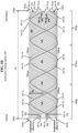
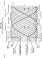
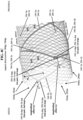
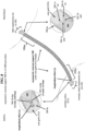
- FIGs. 1A , 1B , and 1C are schematic top, side, and perspective views, respectively, of an exemplary embodiment of the asymmetric external support [indicated as, and referred to by, reference number 100], in the form of a tubular wire braid or mesh, for stabilizing a vein graft used in a coronary arterial bypass graft (CABG) procedure.
- FIGs. 100 are schematic top, side, and perspective views, respectively, of an exemplary embodiment of the asymmetric external support [indicated as, and referred to by, reference number 100], in the form of a tubular wire braid or mesh, for stabilizing a vein graft used in a coronary arterial bypass graft (CABG) procedure.
- CABG coronary arterial bypass graft
- FIGs. 1A , 1B , and 1C show the paired plastically deformable wires ( longitudinally and radially offset ) inter-looped distal end portions (loops), and the paired plastically deformable wires proximal non-connected open ends, with the plastically deformable wires proximal end portions not crossing over or under each other.
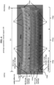
- FIGs. 2A , 2B , and 2C are schematic top, side, and perspective views, respectively, of another exemplary embodiment of the asymmetric external support [indicated as, and referred to by, reference number 200], in the form of a tubular wire braid or mesh, for stabilizing a vein graft used in a coronary arterial bypass graft (CABG) procedure.
- FIGS. 2A , 2B , and 2C show the paired plastically deformable wires ( longitudinally and radially offset ) inter-looped distal end portions (loops), and the paired plastically deformable wires proximal non-connected open ends, with the plastically deformable wires proximal end portions crossing over or under each other.
- Exemplary asymmetric external support 200 shown in FIGs. 2A , 2B , and 2C has all the same structural features, characteristics, and properties as exemplary asymmetric external support 100 shown in FIGs. 1A , 1B , and 1C , except for the particular configuration of the paired plastically deformable wires proximal end portions. Namely, as shown in FIGs. 1A , 1B , and 1C , exemplary external support 100 proximal portion is configured with all of the plastically deformable wires proximal end portions not crossing over or under each other, whereas, as shown in FIGs. 2A , 2B , and 2C , exemplary external support 200 proximal portion is configured with all of the plastically deformable wires proximal end portions crossing over or under each other.
- FIG. 3A is a schematic close-up side view of an exemplary embodiment of the proximal portion of the asymmetric external support (100 of FIGs. 1A , 1B , 1C ), highlighting the paired plastically deformable wires proximal non-connected open ends (coincident with the asymmetric external support proximal end), with the plastically deformable wires proximal end portions not crossing over or under each other.
- FIG. 3B is a schematic close-up side view of an exemplary embodiment of the proximal portion of the asymmetric external support (200 of FIGs.
- FIGs. 4A , 4B , and 4C are schematic close-up top, side, and perspective views, respectively, of an exemplary embodiment of the distal portion of the asymmetric external support (100 of FIGs. 1A , 1B , 1C ; 200 of FIGs.
- FIG. 5 is a schematic close-up side view of an exemplary embodiment of the middle portion of the asymmetric external support (100 of FIGs. 1A , 1B , 1C ; 200 of FIGs. 2A , 2B , 2C ), highlighting the spatially, longitudinally and radially symmetric and uniform tubular wire mesh configuration of non-paired elastic wires and paired plastically deformable wires.
- the exemplary asymmetric external supports (herein, for brevity, also referred to as the supports) 100 shown in FIGs. 1A , 1B , 1C ; and 200 shown in FIGs. 2A , 2B , 2C , are in the forms of tubular wire braids or meshes (herein, also referred to as wire meshes 100 and 200, respectively) longitudinally extending proximally and distally along the full longitudinal length (L) of the support.
- the support (wire mesh) (100; 200) has a proximal portion (100pp; 200pp), a middle portion (100mp; 200mp), a distal portion (100dp; 200dp), a proximal end (100pe; 200pe), and a distal end (100de; 200de).
- the support (wire mesh) (100; 200) has an outer radius (R o ), and has an outer circumferential periphery (or boundary) (100ocp; 200ocp) that spans along, and parallel to, the full longitudinal length (L) of the support (wire mesh) (100; 200).
- the outer circumferential periphery (100ocp; 200ocp) corresponds to the (virtual or effective) circular (tubular) surface that surrounds (encircles, encompasses, bounds) the support (wire mesh) (100; 200) along, and parallel to, its full longitudinal length (L).
- the outer circumferential periphery (100ocp; 200ocp) is formed by the (virtual or effective) circumferential lines ( i.e.
- the support (wire mesh) (100; 200) is configured with non-paired elastic wires (102; 202) and paired plastically deformable wires (104; 204).
- each support (wire mesh) (100; 200) has an exemplary total number of 42 wires (or filaments), including an exemplary total number of 38 non-paired elastic wires (filaments) (102; 202), and an exemplary total number of 4 paired plastically deformable wires (filaments) (104; 204) corresponding to two pairs of two plastically deformable wires (filaments).
- the first pair of plastically deformable wires is indicated as, and referenced by, reference number 104-1, which includes a first pair, first plastically deformable wire 104-1a, and a first pair, second plastically deformable wire 104-1b.
- the second pair of plastically deformable wires is indicated as, and referenced by, reference number 104-2, which includes a second pair, first plastically deformable wire 104-2a and a second pair, second plastically deformable wire 104-2b.
- the first pair of plastically deformable wires is indicated as, and referenced by, reference number 204-1, which includes a first pair, first plastically deformable wire 204-1a, and a first pair, second plastically deformable wire 204-1b.
- the second pair of plastically deformable wires is indicated as, and referenced by, reference number 204-2, which includes a second pair, first plastically deformable wire 204-2a and a second pair, second plastically deformable wire 204-2b.
- the non-paired elastic wires (102; 202) longitudinally extend along the full longitudinal length (L) of the support (wire mesh) (100; 200), whereby the proximal ends (102pe; 202pe) of the elastic wires (102, 202) coincide with the support (wire mesh) proximal end (100pe; 200pe), and the distal ends (102de; 202de) of the elastic wires (102; 202) coincide with the support (wire mesh) distal end (100de; 200de).
- the non-paired elastic wires (102; 202) circumferentially outwardly facing external surfaces coincide with, and 'physically' define, the support (wire mesh) outer circumferential periphery (100ocp; 200ocp).
- the support (wire mesh) proximal portion (100pp; 200pp) is configured with all the paired plastically deformable wires (104; 204) having proximal ends (104-1a pe, 104-1b pe, 104-2a pe, 104-2b pe; 204-1a pe, 204-1b pe, 204-2a pe, 204-2b pe) that are non-connected ( i . e ., not connected to, or looped (inter-looped) with, any other wire of the support (wire mesh)) and are open.
- the support (wire mesh) proximal portion (100pp; 200pp) is configured with all the paired plastically deformable wires (104; 204) having proximal ends (104-1a pe, 104-1b pe, 104-2a pe, 104-2b pe; 204-1a pe, 204-1b pe, 204-2a pe, 204-2b pe) that are coincident with the support (wire mesh) proximal end (100pe; 200pe).
- the support (wire mesh) proximal portion (100pp; 200pp) is configured with not all (e.g., only one of, or even none of) the paired plastically deformable wires (104; 204) having proximal ends that are coincident with the support (wire mesh) proximal end (100pe; 200pe).
- all of the paired plastically deformable wires (104) have proximal end portions (1 04-1a pep, 104-1b pep, 104-2a pep, 104-2b pep) that do not cross over or under each other, whereby, in each pair (104-1, 104-2) of the plastically deformable wires (104), the proximal end portion of the first wire does not cross over or under the proximal end portion of the second wire.
- first wire (104-1a) does not cross over or under the proximal end portion (104-1b pep) of the first pair, second wire (104-1b).
- second wire (104-2b) does not cross over or under the proximal end portion (104-2b pep) of the second pair, second wire (104-2b).
- all of the paired plastically deformable wires (204) have proximal end portions (204-1a pep, 204-1b pep, 204-2a pep, 204-2b pep) that cross over or under each other, whereby, in each pair (204-1, 204-2) of the plastically deformable wires (204), the proximal end portion of the first wire crosses over or under the proximal end portion of the second wire.
- first wire (204-1a) crosses over or under the proximal end portion (204-1b pep) of the first pair, second wire (204-1b).
- second wire (204-1b) crosses over or under the proximal end portion (204-2b pep) of the second pair, second wire (204-2b).
- asymmetric external support (100; 200) was developed in a 'customizable' manner, according to different particular scenarios, conditions, and parameters of different CABG procedures, and based on actual empirical (clinical) data and information obtained from performing CABG procedures using external supports on arterial vein grafts.
- Such customization was implemented in order to produce different possible embodiments / configurations of the support (wire mesh) distal portion (100dp; 200dp) wherein the paired plastically deformable wires (104; 204) are configured with pairs of inter-looped distal end portions (i.e. , in each pair of the plastically deformable wires, a first wire has a distal end portion configured as a first loop, that is inter-looped with a second loop of a second wire distal end portion.
- the plastically deformable wires distal end portions (loops) exhibit different degrees of mobility (i.e., from relatively high mobility to relatively low mobility), or full immobility (i.e., being fixed). Since the support (wire mesh) distal portion (100dp; 200dp) consists of the non-paired elastic wires (102; 202) closely braided or meshed (intertwined, interwoven) with, and physically contacting, the paired plastically deformable wires (104; 204), therefore, particular structural / mechanical configurations, along with mobility, or immobility, of the paired plastically deformable wires inter-looped distal end portions (loops) can, and are expected to, affect the structural / mechanical performance of immediately adjacent, and neighboring, non-paired elastic wires (102; 202) in the support (wire mesh) distal portion (100dp; 200dp).
- Customization of different possible embodiments / configurations of the asymmetric external support (100; 200), in general, and of the support (wire mesh) distal portion (100dp; 200dp), in particular, can translate into having support 'structural / mechanical' features exhibit different (favorable) performance characteristics during initial application and implantation (via an operator) of the support, and during the lifetime (in a patient) of the support. That, in turn, can translate into further improving SVG patency and safe use, as well as operator ( e . g ., surgeon) handling and manipulating characteristics, of the support for externally stenting an arterial vein graft used in a human CABG procedure.
- the paired plastically deformable wires (104; 204) are configured with inter-looped distal end portions (loops), whereby each pair (104-1, 104-2; 204-1, 204-2) of the plastically deformable wires (104; 204) has a first wire distal end portion formed as a first wire closed loop [1st loop] that is looped (i.e., inter-looped) with a second wire distal end portion formed as a second wire closed loop [2nd loop].
- each pair of the plastically deformable wires has a first wire whose distal end portion forms a first wire closed loop [1st loop] with a first wire loop end back-folded upon the first wire (so as to close the 1st loop), and has a second wire whose distal end portion forms a second wire closed loop [2nd loop] with a second wire loop end looped (inter-looped) through the first wire closed loop and back-folded upon the second wire (so as to close the 2nd loop).
- the first pair, first wire (104-1a; 204-1a) is configured with an inter-looped distal end portion (104-1a dep [1st pair, 1st loop]; 204-1a [1st pair, 1st loop]), and the first pair, second wire (104-1b; 204-1b) is configured with an inter-looped distal end portion (104-1b dep [1st pair, 2nd loop]; 204-1b dep [1st pair, 2nd loop]).
- the first pair, first wire distal end portion (104-1a dep; 204-1a dep) forms a first pair, first wire closed loop [1st pair, 1st loop], with the end (tip) of the first pair, first wire closed loop [1st pair, 1st loop] back-folded upon the first pair, first wire (104-1a; 204-1a) (so as to close the first pair, first wire closed loop [1st pair, 1st loop]).
- the first pair, second wire distal end portion (104-1b dep; 204-1b dep) forms a first pair, second wire closed loop [1st pair, 2nd loop], with the end (tip) of the first pair, second wire closed loop [1st pair, 2nd loop] looped (inter-looped) through the first pair, first wire closed loop [1st pair, 1st loop] and back-folded upon the first pair, second wire (104-1b; 204-1b) (so as to close the first pair, second wire closed loop [1st pair, 2nd loop]).
- the second pair, first wire (104-2a; 204-2a) is configured with an inter-looped distal end portion (104-2a dep [2nd pair, 1st loop]; 204-2a dep [2nd pair, 1st loop]), and the second pair, second wire (104-2b; 204-2b) is configured with an inter-looped distal end portion (104-2b dep [2nd pair, 2nd loop]; 204-2b dep [2nd pair, 2nd loop]).
- the second pair, first wire distal end portion (104-2a dep; 204-2a dep) forms a second pair, first wire closed loop [2nd pair, 1st loop], with the end (tip) of the second pair, first wire closed loop [2nd pair, 1st loop] back-folded upon the second pair, first wire (104-2a; 204-2a) (so as to close the 2nd pair, first wire closed loop [2nd pair, 1st loop]).
- the second pair, second wire distal end portion (104-2b dep; 204-2b dep) forms a second pair, second wire closed loop [2nd pair, 2nd loop], with the end (tip) of the second pair, second wire loop end [2nd pair, 2nd loop] looped (inter-looped) through the second pair, first wire closed loop [2nd pair, 1st loop] and back-folded upon the second pair, second wire (104-2b; 204-2b) (so as to close the 2nd pair, second wire closed loop [2nd pair, 2nd loop]).
- the 'back-fold' of each wire loop end upon its respective wire can have different particular configurations.
- the 'back-fold' of the wire loop end upon the wire is configured, whereby the ultimate end or tip (i.e. , the utmost, farthest, or most distant part) of the wire loop end is aligned (so as to be co-axial / co-linear), and makes physical contact, with a particular segment or point along the remaining part of its respective wire.
- the 'back-fold' of the wire loop end upon the wire is configured, whereby the ultimate end or tip (i.e., the utmost, farthest, or most distant part) of the wire loop end crosses over or under, and onto its respective wire, in an ⁇ x-like' transverse manner, so as to slightly extend past the wire (e.g., by a relatively small distance of 0.2 mm - 2 mm), with a particular segment of that extended wire making physical contact with a particular segment or point along the remaining part of its respective wire.
- the ultimate end or tip i.e., the utmost, farthest, or most distant part
- the wire loop end crosses over or under, and onto its respective wire, in an ⁇ x-like' transverse manner, so as to slightly extend past the wire (e.g., by a relatively small distance of 0.2 mm - 2 mm), with a particular segment of that extended wire making physical contact with a particular segment or point along the remaining part of its respective wire.
- the two individual loops i.e., the two individual looped distal end portions that are inter-looped with each other
- the two individual loops are configured so as to be (longitudinally or/and radially) slidably movable relative to each other.
- the loop (inter-looped distal end portion) of the first wire and the loop (inter-looped distal end portion) of the second wire are (longitudinally or/and radially) slidably movable relative to each other.
- each pair (104-1, 104-2; 204-1, 204-2) of the plastically deformable wires (104; 204), the first wire distal end portion (formed as the first wire closed loop [1st loop]) and the second wire distal end portion (formed as the second wire closed loop [2nd loop]), that are inter-looped with each other, are configured so as to be (longitudinally or/and radially) slidably movable relative to each other.
- the first pair (104-1; 204-1) of plastically deformable wires (104; 204) the first pair, first wire looped distal end portion (104-1a dep [1st pair, 1st loop]; 204-1a [1st pair, 1st loop]) and the first pair, second wire looped distal end portion (104-1b dep [1st pair, 2nd loop]; 204-1b dep [1st pair, 2nd loop]), that are inter-looped with each other, are configured so as to be (longitudinally or/and radially) slidably movable relative to each other.
- the second pair (104-2; 204-2) of plastically deformable wires (104; 204) the second pair, first wire looped distal end portion (104-2a dep [2nd pair, 1st loop]; 204-2a dep [2nd pair, 1st loop]) and the second pair, second wire looped distal end portion (104-2b dep [2nd pair, 2nd loop]; 204-2b dep [2nd pair, 2nd loop]), that are inter-looped with each other, are configured so as to be (longitudinally or/and radially) slidably movable relative to each other.
- Such exemplary embodiments of the inter-looped distal end portions (loops) being slidably movable relative to each other require that, not both, but, at least one, of the two individual loops (i.e., at least one of the two individual looped distal end portions that are inter-looped with each other) in each pair (104-1, 104-2; 204-1, 204-2) of the plastically deformable wires (104; 204) is configured with a sufficiently large loop size that facilitates the (radial or/and longitudinal) slidable mobility of the two loops relative to each other.
- both of the two individual loops in each pair (104-1, 104-2; 204-1, 204-2) of the plastically deformable wires (104; 204) are configured with a sufficiently large loop size that facilitates the slidable mobility of the two loops relative to each other.
- the two individual loops i.e., the two individual looped distal end portions that are inter-looped with each other
- the two individual loops are configured so as not to be slidably movable ( i.e. , they are immobile, or fixed in place) relative to each other.
- the loop (inter-looped distal end portion) of the first wire and the loop (inter-looped distal end portion) of the second wire are not (longitudinally or/and radially) slidably movable relative to each other, rather, the loops of the first and second wires are immobile, or fixed, relative to each other.
- each pair (104-1, 104-2; 204-1, 204-2) of the plastically deformable wires (104; 204), the first wire distal end portion (formed as the first wire closed loop [1st loop]) and the second wire distal end portion (formed as the second wire closed loop [2nd loop]), that are inter-looped with each other, are configured so as not to be slidably movable ( i.e. , they are immobile, or fixed in place) relative to each other.
- the first pair (104-1; 204-1) of plastically deformable wires (104; 204) the first pair, first wire looped distal end portion (104-1a dep [1st pair, 1st loop]; 204-1a [1st pair, 1st loop]) and the first pair, second wire looped distal end portion (104-1b dep [1st pair, 2nd loop]; 204-1b dep [1st pair, 2nd loop]), that are inter-looped with each other, are configured so as not to be slidably movable (i.e., they are immobile, or fixed in place) relative to each other.
- the second pair (104-2; 204-2) of plastically deformable wires (104; 204) the second pair, first wire looped distal end portion (104-2a dep [2nd pair, 1st loop]; 204-2a dep [2nd pair, 1st loop]) and the second pair, second wire looped distal end portion (104-2b dep [2nd pair, 2nd loop]; 204-2b dep [2nd pair, 2nd loop]), that are inter-looped with each other, are configured so as not to be slidably movable (i.e., they are immobile, or fixed in place) relative to each other.
- Such exemplary embodiments of the inter-looped distal end portions (loops) not being slidably movable (i.e., being immobile, fixed in place) relative to each other require that, not both, but, at least one, of the two individual loops ( i.e. , at least one of the two individual looped distal end portions that are inter-looped with each other) in each pair (104-1, 104-2; 204-1, 204-2) of the plastically deformable wires (104; 204) is configured with a sufficiently small loop size that fully prevents (radial or longitudinal) slidable mobility of the two loops relative to each other.
- both of the two individual loops in each pair (104-1, 104-2; 204-1, 204-2) of the plastically deformable wires (104; 204) are configured with a sufficiently small loop size that fully prevents slidable mobility of the two loops relative to each other.
- the loop size may be quantifiable and measurable, for example, in terms of the inner [circular or elliptical loop-shape] area of, and encompassed by, a single loop, which is then used for (custom) designing, and subsequently forming, the inter-looped distal end portions (loops) of the paired plastically deformable wires (104; 204) in the support (wire mesh) distal portion (100dp; 200dp).
- having the ability to control the loop size translates into having the ability to control the degree or extent of mobility, or immobility, provided to the paired plastically deformable wires inter-looped distal end portions (loops) in the support (wire mesh) distal portion (100dp; 200dp).
- This facilitates the asymmetric external support (100; 200) structural / mechanical features to exhibit different (favorable) 'customized' performance characteristics during initial application and implantation (via an operator) of the support, and during the lifetime (in a patient) of the support.
- each pair of the plastically deformable wires has a first wire whose distal end portion forms a first wire closed loop [1st loop] with a first wire loop end back-folded upon the first wire (so as to close the 1st loop), and has a second wire whose distal end portion forms a second wire closed loop [2nd loop] with a second wire loop end looped (inter-looped) through the first wire closed loop and back-folded upon the second wire (so as to close the 2nd loop).
- each wire despite each closed loop having its end back-folded upon the wire (so as to close the loop), the possibility exists that its closed loop may loosen, become unlooped, and open up, during initial application and implantation of the support by an operator of the CABG procedure, or/and during the lifetime of the support in a patient, which, could lead to the support (wire mesh) distal portion (100dp; 200dp), with wires of the open loop(s), injuring (via plastically deformable wires pricking or piercing) heart or/and vascular tissue.
- Such exemplary embodiments are based on using a loop closure securing (reinforcing) procedure, in particular, (i) a loop closure adhering procedure, or (ii) a loop closure heat treatment ( e . g ., a laser welding, or a laser soldering) procedure.
- each inter-looped distal end portion (loop) has a loop closure (i.e., the closure [closed part] of the loop) that is individually secured or reinforced, via use of a loop closure securing (reinforcing) procedure, in particular, above listed (i) or (ii).
- each loop closure (the closure [closed part] of each loop of the two (inter-looped) loops in each inter-looped distal end portion) is individually secured or reinforced (via above (i) or (ii)), specifically at the particular location or point which the wire loop end is back-folded upon, and makes physical contact with, its respective wire.
- each inter-looped distal end portion (loop) has a loop closure (i.e., the closure [closed part] of the loop) that may be individually secured or reinforced, via a loop closure adhering procedure, with adhesive material (e . g ., medical grade glue or other adhesive type material) that is applied to the particular location or point at which the wire loop end is back-folded upon, and makes physical contact with, its respective wire.
- adhesive material e . g ., medical grade glue or other adhesive type material
- the first pair, first wire (104-1a; 204-1a) has an inter-looped distal end portion (104-1a dep [1st pair, 1st loop]; 204-1a [1st pair, 1st loop]) with a loop closure that may be individually secured or reinforced, via a loop closure adhesive procedure, with adhesive material that is applied to the particular location or point at which the wire loop end is back-folded upon, and makes physical contact with, the first pair, first wire (104-1a; 204-1a).
- each inter-looped distal end portion (loop) has a loop closure (i.e., the closure [closed part] of the loop) that may be individually secured or reinforced, via a loop closure heat treatment procedure, with welding or soldering applied to the particular location or point at which the wire loop end is back-folded upon, and makes physical contact with, its respective wire.
- a loop closure i.e., the closure [closed part] of the loop
- the first pair, first wire (104-1a; 204-1a) has an inter-looped distal end portion (104-1a dep [1st pair, 1st loop]; 204-1a [1st pair, 1st loop]) with a loop closure that may be individually secured or reinforced, via a loop closure heat treatment procedure, with welding or soldering applied to the particular location or point at which the wire loop end is back-folded upon, and makes physical contact with, the first pair, first wire (104-1a; 204-1a).
- the loop closure securing (reinforcing) procedure can be performed in order to produce different possible embodiments / configurations of the individually secured (reinforced) loop closures, such that in each pair (104-1, 104-2; 204-1, 204-2) of the plastically deformable wires (104; 204), and in the inter-looped distal end portions thereof, the two closed loops with their two respective individually secured (reinforced) loop closures, can exhibit different degrees of relative mobility, or full immobility ( i.e. , being fixed), as described hereinabove.
- the two loop closures can be individually subjected to the loop closure securing (reinforcing) procedure (via above (i) or (ii)), in order to produce two respective individually secured (reinforced) loop closures, such that the first pair, first wire inter-looped distal end portion (104-1a dep [1st pair, 1st loop; 204-1a dep [1st pair, 1st loop]) and the first pair, second wire inter-looped distal end portion (104-1b dep [1st pair, 2nd loop]; 204-1b dep [1st pair, 2nd loop]) are to some degree (longitudinally or/and radially) slidably movable relative to each other.
- the two loop closures can be subjected to the loop closure securing (reinforcing) procedure (via above (i) or (ii)), in order to produce two respective individually secured (reinforced) loop closures, such that the first pair, first wire inter-looped distal end portion (104-1a dep [1st pair, 1st loop; 204-1a dep [1st pair, 1st loop]) and the first pair, second wire inter-looped distal end portion (104-1b dep [1st pair, 2nd loop]; 204-1b dep [1st pair, 2nd loop]) are not slidably movable (i.e., they are immobile, or fixed in place) relative to each
- the herein disclosed asymmetric external support (100; 200) was designed, and constructed, wherein the support (wire mesh) distal portion (100dp; 200dp) is configured with the paired plastically deformable wires (104; 204) longitudinally extending along less than the full longitudinal length (L) of the support (wire mesh) (100; 200), whereby the apexes (i.e., the midpoints of the arched parts) of all the looped distal end portions (loops) are proximally longitudinally offset from, and not coincident with, the support (wire mesh) distal end (100de; 200de).
- the support (wire mesh) proximal portion (100pp; 200pp) is configured with all the paired plastically deformable wires (104; 204) having proximal ends that are coincident with the support (wire mesh) proximal end (100pe; 200pe).
- the support (wire mesh) proximal portion (100pp; 200pp) is configured with not all (e.g., only one of, or even none of) the paired plastically deformable wires (104; 204) having proximal ends that are coincident with the support (wire mesh) proximal end (100pe; 200pe).
- the paired plastically deformable wires (104; 204) longitudinally extend along less than the full longitudinal length (L) of the support (wire mesh) (100; 200), whereby the apexes (midpoints of the arched parts) of all the looped distal end portions (104-1a dep [1st pair, 1st loop], 104-1b [1st pair, 2nd loop], 104-2a dep [2nd pair, 1st loop], 104-2b dep [2nd pair, 2nd loop]; 204-1a dep [1st pair, 1st loop], 204-1b [1st pair, 2nd loop], 204-2a dep [2nd pair, 1st loop], 204-2b dep [2nd pair, 2nd loop]) are proximally longitudinally offset from, and not coincident with, the support (wire mesh) distal end (100de; 200de).
- the proximal ends (104-1a pe, 104-1b pe, 104-2a pe, 104-2b pe; 204-1a pe, 204-1b pe, 204-2a pe, 204-2b pe) of all the paired plastically deformable wires (104; 204) are coincident with the support (wire mesh) proximal end (100pe; 200pe).
- the 'longitudinal offset' is indicated as, and referred to by, the reference symbol ⁇ (lambda).
- ⁇ the proximal longitudinal offset ( ⁇ ), of the apex (midpoint of the arched part) of each looped (inter-looped) distal end portion (loop) of each plastically deformable wire (104; 204) from the (ultimate) distal end (100de; 200de) of the support (wire mesh) (100; 200), has a magnitude in a range of between 0.2 mm and 1.5 mm.
- first wire (104-1a; 204-1a) of plastically deformable wires (104; 204) has a proximal longitudinal offset ( ⁇ ) from the support (wire mesh) distal end (100de; 200de), and the proximal end (104-1a pe; 204-1a pe) of the first pair, first wire (104-1a; 204-1a) is coincident with the support (wire mesh) proximal end (100pe; 200pe).
- the apex (arched part midpoint) of the looped distal end portion (104-2b dep [2nd pair, 2nd loop]; 204-2b dep [2nd pair, 2nd loop]) has a proximal longitudinal offset ( ⁇ ) from the support (wire mesh) distal end (100de; 200de), and the proximal end (104-2b pe; 204-2b pe) of the second pair, second wire (104-2b; 204-2b) is coincident with the support (wire mesh) proximal end (100pe; 200pe).
- FIGs. 1A , 2A , and 4A which particularly show the radial offset ( ⁇ ) of the inter-looped distal end portions (loops) of the plastically deformable wires (104; 204), compared to the other figures of the asymmetric external support (100; 200) wherein the radial offset ( ⁇ ) of the paired plastically deformable wires inter-looped distal end portions (loops) is present, but, not readily viewable.
- the herein disclosed asymmetric external support (100; 200) was designed, and constructed, wherein the support (wire mesh) distal portion (100dp; 200dp) has all the paired plastically deformable wires (104; 204) configured such that the first and second wire closed loops of the inter-looped distal end portions radially extend beyond the outer radius (R o ) of the support (wire mesh) (100; 200).
- the apexes (midpoints of the arched parts) of all the looped (inter-looped) distal end portions (loops) are outwardly radially offset from, and not coincident with, the outer circumferential periphery (100ocp; 200ocp) of the support (wire mesh) (100; 200).
- the non-paired elastic wires (102; 202) circumferentially outwardly facing external surfaces coincide with, and define, the support (wire mesh) outer circumferential periphery (100ocp; 200ocp).
- such radial extension beyond the outer radius (R o ) of the support (wire mesh) (100; 200), and outwardly radial offset from, and non-coincidence with, the support (wire mesh) outer circumferential periphery (100ocp; 200ocp), corresponds to the plastically deformable wires inter-looped distal end portions (loops) projecting (protruding, jutting, extending, sticking) out or outwardly from the outer radius (R o ) of the support (wire mesh) (100; 200), whereby the apexes (midpoints of the arched parts) of all the looped distal end portions (loops) project (protrude, jut, extend, stick) out or outwardly from the outer circumferential periphery (100ocp; 200ocp) of the support (wire mesh) (100; 200).
- the ⁇ radial offset' is indicated as, and referred to by, the reference symbol ⁇ (delta).
- the outward radial offset ( ⁇ ) of the apex (midpoint of the arched part) of each looped distal end portion of each plastically deformable wire (104; 204) out or outwardly from the outer circumferential periphery (100ocp; 200ocp) of the support (wire mesh) (100; 200), has a magnitude in a range of between 0.2 mm and 1.5 mm.
- first wire (104-2a; 204-2a) of plastically deformable wires (104; 204) the looped distal end portion (104-2a dep [2nd pair, 1st loop]; 204-2a dep [2nd pair, 1st loop]) radially extends beyond the outer radius (R o ) of the support (wire mesh) (100; 200), whereby the apex (arched part midpoint) of that looped distal end portion has an outward radial offset ( ⁇ ) from, and is not coincident with, the outer circumferential periphery (100ocp; 200ocp) of the support (wire mesh) (100; 200).
- first wire (104-1a; 204-1a) of plastically deformable wires (104; 204) the looped distal end portion (104-1a dep [1st pair, 1st loop]; 204-1a dep [1st pair, 1st loop]) radially extends beyond the outer radius (R o ) of the support (wire mesh) (100; 200), whereby the apex (arched part midpoint) of that looped distal end portion has an outward radial offset ( ⁇ ) from, and is not coincident with, the outer circumferential periphery (100ocp; 200ocp) of the support (wire mesh) (100; 200).
- the structural (geometrical and mechanical) features, properties, and characteristics of the non-paired elastic wires (102; 202) are spatially, longitudinally and radially symmetric and uniform
- the structural (geometrical and mechanical) features, properties, and characteristics of the paired plastically deformable wires (104; 204) are spatially, longitudinally and radially symmetric and uniform.
- the asymmetric external support (100; 200) is spatially, 'longitudinally and radially' asymmetric (i.e. , lacks symmetry) with respect to the opposing proximal and distal portions (100pp; 200pp, and 100dp; 200dp), and the respective opposing proximal and distal ends therein (100pe; 200pe, and 100de; 200de).
- asymmetric external support (100; 200)
- particular structural (geometrical and mechanical) features, properties, and characteristics are spatially, 'longitudinally and radially asymmetric' with respect to the opposing proximal and distal portions (100pp; 200pp, and 100dp; 200dp), and the respective opposing proximal and distal ends (100pe; 200pe, and 100de; 200de) therein.
- the support (wire mesh) distal portion (100dp; 200dp), including the distal end (100de; 200de) therein exhibits, and is characterized by, particular structural (geometrical and mechanical) features, properties, and characteristics that are asymmetric relative to, and substantially different from, the particular structural (geometrical and mechanical) features, properties, and characteristics exhibited by, and characterizing, the support (wire mesh) proximal portion (100pp; 200pp), including the proximal end (100pe; 200pe) therein.
- a first asymmetric feature is that in the support (wire mesh) distal portion (100dp; 200dp), all paired plastically deformable wires (104; 204) are configured with looped distal end portions (104-1a dep [1st loop], 104-1b dep [2nd loop], 104-2a [1st loop], 104-2b [2nd loop]; 204-1a [1st loop], 204-1b [2nd loop], 204-2a [1st loop], 204-2b [2nd loop]) having closed ends, and in the support (wire mesh) proximal portion (100pp; 200pp), all paired plastically deformable wires are configured with non-looped, non-connected proximal end portions (104-1a pep, 104-1b pep, 104-2a pep, 104-2b pep; 204-1a pep, 204-1b pep, 204-2a pep, 204-2b pep) having open ends.
- the support (wire mesh) distal portion (100dp; 200dp) is configured with looped pairs of plastically deformable wires having closed ends
- the support (wire mesh) proximal portion (100pp; 200pp) is configured with non-looped, non-connected pairs of plastically deformable wires having open ends.
- a second asymmetric feature is that the paired plastically deformable wires (104; 204) longitudinally extend along less than the full longitudinal length (L) of the support (wire mesh) (100; 200), whereby the apexes (midpoints of the arched parts) of all the looped distal end portions are proximally longitudinally offset from, and not coincident with, the (ultimate) distal end (100de; 200de) of the support (wire mesh) (100; 200).
- the proximal ends of all the paired plastically deformable wires are coincident with the (ultimate) proximal end (100pe; 200pe) of the support (wire mesh) (100; 200).
- the support (wire mesh) distal end (100de; 200de) is not coincident with the longitudinally offset apexes of all the looped distal end portions of the paired plastically deformable wires (104; 204)
- the support (wire mesh) proximal end (100pe; 200pe) is coincident with the proximal ends of all the paired plastically deformable wires (104; 204).
- a third asymmetric feature is that in the support (wire mesh) distal portion (100dp; 200dp), all the paired plastically deformable wires (104; 204) are configured with the looped distal end portions (loops) radially extending beyond the outer radius (R o ) of the support (wire mesh) (100; 200), whereby the apexes (midpoints of the arched parts) of all the looped distal end portions (loops) are outwardly radially offset from, and not coincident with, the outer circumferential periphery (100ocp; 200ocp) of the support (wire mesh) (100; 200).
- the outer circumferential periphery (100ocp; 200ocp) of the support (wire mesh) distal portion (100dp; 200dp) is not coincident with the radially offset apexes of all the looped distal end portions of the paired plastically deformable wires (104; 204)
- the outer circumferential periphery (100ocp; 200ocp) of the support (wire mesh) proximal portion (100pp; 200pp) is coincident with the proximal ends of all the paired plastically deformable wires (104; 204).
- the asymmetric external support (100; 200) is externally applicable upon, to cover, a vein graft in a manner such that the support (wire mesh) distal portion (100dp; 200dp), with the support (wire mesh) distal end (100de; 200de) therein, is positionable at a coronary artery anastomosis site, and the support (wire mesh) proximal portion (100pp; 200pp), with the support (wire mesh) proximal end (100pe; 200pe) therein, is positionable at an other anastomosis site.
- the apexes of all the looped distal end portions (loops), and therefore, the distal-most parts, of all the paired plastically deformable wires (104; 204) in the support (wire mesh) distal portion (100dp; 200dp) will be proximally longitudinally located away (by more than the loops apexes proximal longitudinal offset ( ⁇ ) [ e.g. , 0.2 mm -1.5 mm]) from, and not coincident with, the coronary artery anastomosis site.
- exemplary other anastomosis sites are: (1) the aorta (more than 90 % of time); (2) another venous graft (e.g., an SVG) anastomized directly to the aorta; (3) an arterial graft (e.g., a radial artery graft) anastomized to a coronary artery and to the aorta; and (4) an internal mammary artery.
- another venous graft e.g., an SVG
- an arterial graft e.g., a radial artery graft
- Length (L) 2.5 cm - 12 cm; for example, 6, 7, or 8 cm, in its longitudinally ⁇ relaxed' configuration, prior to deployment and in-vivo implantation via a CABG procedure. 7 cm - 36 cm, in its longitudinally 'expanded' configuration after deployment and in-vivo implantation via a CABG procedure.
- Wire mesh braiding angle 0 degrees - 180 degrees; for example, 10 degrees, 30 degrees, 45 degrees, 60 degrees, 90 degrees, 120 degrees, 150 degrees.
- Total number of wires (fibers, filaments, threads): 24 - 156.
- 24 - 156 For example, 24, 36, 42, 64, 128, 156 individual (non-paired elastic + plastically deformable) wires.
- Non-paired elastic wires fibers, filaments, threads
- 102 Non-paired elastic wires (fibers, filaments, threads) 102; 202
- cold worked metals or cold worked metal alloys, for example, of cobalt, chrome, nickel, titanium, aluminum, stainless steel; characterized by exhibiting 'elasticity', being 'elastic', and having 'elastic' properties.
- Diameter 10 microns (0.01 cm) - 100 microns (0.1 cm).
- Total number of individual elastic wires in tubular wire mesh (100; 200): 20 - 124.
- 20 - 124 For example, 20, 38, 60, 124 individual, non-paired elastic wires.
- heat treated (hot worked, annealed) metals or heat treated (hot worked, annealed) metal alloys, for example, of cobalt, chrome, nickel, titanium, aluminum, stainless steel; characterized by exhibiting 'plasticity', being ⁇ plastically deformable', and having ⁇ plastically deformable' properties.
- Diameter 50 microns (0.05 cm) - 200 microns (0.2 cm).
- Total number of individual plastically deformable wires in tubular wire mesh (100; 200): 4 - 32.
- 4 - 32 Total number of individual plastically deformable wires in tubular wire mesh.
- the loops of the support (wire mesh) are manually made (formed) by inserting a mandrel (rod, shaft) into the support (wire mesh) so as to firmly hold and fix the support (wire mesh) in place.
- the support (wire mesh), with mandrel inside, is then placed on the platform of a microscope, and a tweezer (pincers) is used to delicately manipulate and bend (fold, and back-fold) each plastically deformable wire distal end portion into the form of a (circular or elliptical shaped loop), followed by inter-looping two looped wires for forming an inter-looped pair of the plastically deformable wires.
- the first wire distal end portion is formed into a first wire closed loop [1st loop] with a first wire loop end back-folded upon the first wire (so as to close the 1st loop).
- the second wire distal end portion is formed into a second wire closed loop [2nd loop], with a second wire loop end looped (inter-looped) through the first wire closed loop and back-folded upon the second wire (so as to close the 2nd loop).
- FIGs. 6 and 7 are exemplary micrographs (photographs as viewed through a microscope) of an exemplary (actual) prototype of the herein disclosed asymmetric external support [indicated as, and referred to by, reference number 120], for stabilizing a vein graft used in a coronary arterial bypass graft (CABG) procedure.
- Exemplary prototype asymmetric external support 120 shown in FIGs. 6 and 7 , was designed and constructed in accordance with the schematic views of the exemplary embodiment of the asymmetric external support 100 shown in FIGs. 1A , 1B , 1C , 4A , 4B , 4C , and 5 .
- FIG. 1A , 1B , 1C , 4A , 4B , 4C , and 5 In FIG.
- the exemplary micrograph is of a top view of the exemplary prototype asymmetric external support 120, being analogous to the schematic top view of the exemplary asymmetric external support 100 shown in FIG. 1A .
- the exemplary micrograph is of a close-up top view of the distal portion of the exemplary prototype asymmetric external support 120, being analogous to the schematic close-up top view of the distal portion of the exemplary asymmetric external support 100 shown in FIG. 4A .
- Exemplary prototype asymmetric external support 120 shown in FIGs. 6 and 7 has all the same structural and functional features, characteristics, and properties as illustratively described above for exemplary asymmetric external support (wire mesh) 100 shown in FIGs. 1 , 4 , and 5 .
- Exemplary prototype asymmetric external support 120 is in the form of a tubular wire mesh longitudinally extending proximally and distally along the full longitudinal length (L) of the support [6.5 cm, in its relaxed configuration prior to deployment in a CABG procedure].
- the prototype support (wire mesh) 120 has a proximal portion 120pp, a middle portion 120mp, a distal portion 120dp, a proximal end 120pe, a distal end 120de, and an outer circumferential periphery (boundary) 120ocp [with outer radius (R o ) equal to 3.5 mm (diameter of 7 mm)] that spans along, and parallel to, the full longitudinal length (L) of the prototype support (wire mesh) 120.
- Prototype support (wire mesh) 120 is configured with non-paired elastic wires 102 [cobalt chrome, 0.038 mm (38 microns) diameter] and paired plastically deformable wires 104 [cobalt chrome, 0.106 mm (106 microns) diameter].
- Prototype support (wire mesh) 120 has an exemplary total number of 42 wires (filaments), including an exemplary total number of 38 non-paired elastic wires (filaments) 102, and an exemplary total number of 4 paired plastically deformable wires (filaments) 104 corresponding to two pairs of two plastically deformable wires (filaments).
- the proximal ends of all the paired plastically deformable wires 104 are non-connected (i.e., not connected to any other wire of the prototype support (wire mesh)) and are open. Additionally, in the prototype support (wire mesh) proximal portion 120pp, all of the paired plastically deformable wires 104 have proximal end portions that do not cross over or under each other, whereby, in each pair (104-1, 104-2) of the plastically deformable wires (104), the proximal end portion of the first wire does not cross over or under the proximal end portion of the second wire.
- the structural (geometrical and mechanical) features, properties, and characteristics of the non-paired elastic wires 102 and of the paired plastically deformable wires 104 are spatially, longitudinally and radially symmetric and uniform.
- the paired plastically deformable wires 104 are configured with ( longitudinally and radially offset ) inter-looped distal end portions (loops).
- Each pair 104-1, 104-2 of the plastically deformable wires 104 has a first wire distal end portion formed as a first wire closed loop [1st loop] that is looped ( i.e. , inter-looped) with a second wire distal end portion formed as a second wire closed loop [2nd loop].
- each inter-looped distal end portion is configured with a loop closure (i.e. , the closure [closed part] of the loop) that is individually secured or reinforced, via a loop closure heat treatment procedure, by welding the particular location or point at which the wire loop end is back-folded upon, and makes physical contact with, its respective wire.
- the two individual loops i.e. , the two individual looped distal end portions that are inter-looped with each other
- the paired plastically deformable wires 104 longitudinally extend along less than the full longitudinal length (L) of the prototype support (wire mesh) 120, whereby the apexes (midpoints of the arched parts) of all the looped distal end portions (loops) are proximally longitudinally offset from, and not coincident with, the prototype support (wire mesh) distal end 120de.
- the proximally longitudinal offset ( ⁇ ) of the apex (midpoint of the arched part) of each looped distal end portion (loop) from the (ultimate) distal end 120de of the prototype support (wire mesh) 120 has a magnitude of 0.75 mm.
- the paired plastically deformable wires 104 are configured with the inter-looped distal end portions (loops) radially extending beyond the outer radius (R o ) of the prototype support (wire mesh) 120, whereby the apexes (midpoints of the arched parts) of all the looped distal end portions (loops) are outwardly radially offset from, and not coincident with, the outer circumferential periphery 120ocp of the prototype support (wire mesh) 120.
- the outward radial offset ( ⁇ ) of the apex (midpoint of the arched part) of each looped distal end portion (loop) radially extending beyond the outer circumferential periphery 120ocp of the prototype support (wire mesh) 120 has a magnitude of 0.5 mm.
- the prototype support 120 in a coronary arterial bypass graft (CABG) procedure, is externally applicable upon, to cover, a vein graft in a manner such that the prototype support (wire mesh) distal portion 120dp (with distal end 120de therein) is positionable at a coronary artery anastomosis site, and the prototype support (wire mesh) proximal portion 120pp (with proximal end 120pe therein) is positionable at an other anastomosis site.
- CABG coronary arterial bypass graft
- asymmetric external support 100 or 200
- CABG coronary arterial bypass graft
- FIG. 8 is a schematic diagram showing an exemplary embodiment of application of the exemplary asymmetric external support 200 ( e . g ., shown in FIGs. 2A , 2B , 2C ), in a CABG procedure, highlighting particular directional positioning of a vein graft (VG) externally covered and supported by exemplary asymmetric external support 200, with respect to a coronary artery anastomosis site (ca-AS) and an other anastomosis site (o-AS).
- VG vein graft
- the paired plastically deformable wires (204) have proximal end portions (e . g ., 204-1a pep, and 204-1b pep) that cross over or under each other.
- the paired plastically deformable wires (204) are configured with inter-looped distal end portions (loops) (e.g., 204-1a dep [1st pair, 1st loop], and 204-1b dep [1st pair, 2nd loop]).
- the paired plastically deformable wires (204) longitudinally extend along less than the full longitudinal length (L) of the support 200, whereby the apexes of the looped distal end portions (204-1a dep [1st pair, 1st loop], 204-1b dep [1st pair, 2nd loop]) are proximally longitudinally offset from, and not coincident with, the support distal end (200de).
- the proximal ends (204-1a pe, 204-1b pe) of the paired plastically deformable wires (204) are coincident with the support proximal end (200pe).
- the asymmetric external support 200 is externally applicable upon, to cover, the vein graft (VG) in a manner such that the support distal portion (200dp), with the support distal end (200de) therein, will be positioned at the coronary artery anastomosis site (ca-AS), and the support proximal portion (200pp), with the support proximal end (200pe) therein, will be positioned at the other anastomosis site (o-AS).
- the apexes of the looped distal end portions (loops) (204-1a dep [1st pair, 1st loop], and 204-1b [1st pair, 2nd loop]), and therefore, the distal-most parts, of the paired plastically deformable wires (204) in the support distal portion (200dp) will be proximally longitudinally located away (by more than the loops apexes proximal longitudinal offset ( ⁇ ) [ e.g.
- the other anastomosis site may be, for example: (1) the aorta (more than 90 % of time); (2) another venous graft (e.g., an SVG) anastomized directly to the aorta; (3) an arterial graft (e.g., a radial artery graft) anastomized to a coronary artery and to the aorta; or (4) an internal mammary artery.
- another venous graft e.g., an SVG
- an arterial graft e.g., a radial artery graft
- 'a', 'an', and ⁇ the' means ⁇ at least one', or ⁇ one or more'. Use of the phrase ⁇ one or more' herein does not alter this intended meaning of 'a', 'an', or 'the'. Accordingly, the terms 'a', 'an', and ⁇ the', as used herein, may also refer to, and encompass, a plurality of the stated entity or object, unless otherwise specifically defined or stated herein , or, unless the context clearly dictates otherwise.
- phrases: ⁇ a unit', ⁇ a device', ⁇ an assembly', ⁇ a mechanism', ⁇ a component', ⁇ an element', and ⁇ a step or procedure' may also refer to, and encompass, a plurality of units, a plurality of devices, a plurality of assemblies, a plurality of mechanisms, a plurality of components, a plurality of elements, and, a plurality of steps or procedures, respectively.
- Each of these terms is considered equivalent in meaning to the phrase ⁇ consisting essentially of.
- each of the phrases ⁇ consisting essentially of, and ⁇ consists essentially of, as used herein, means that the stated entity or item (system, system unit, system sub-unit, device, assembly, sub-assembly, mechanism, structure, component, element, or, peripheral equipment, utility, accessory, or material, method or process, step or procedure, sub-step or sub-procedure), which is an entirety or part of an exemplary embodiment of the disclosed invention, or/and which is used for implementing an exemplary embodiment of the disclosed invention, may include at least one additional 'feature or characteristic' being a system unit, system sub-unit, device, assembly, sub-assembly, mechanism, structure, component, or element, or, peripheral equipment, utility, accessory, or material, step or procedure, sub-step or sub-procedure), but only if each such additional ⁇ feature or characteristic' does not materially alter the basic novel and inventive characteristics or special technical features, of the claimed entity or item.
- 'method' refers to a single step, procedure, manner, means, or/and technique, or a sequence, set, or group of two or more steps, procedures, manners, means, or/and techniques, for accomplishing or achieving a given task or action.
- Any such herein disclosed method in a non-limiting manner, may include one or more steps, procedures, manners, means, or/and techniques, that are known or readily developed from one or more steps, procedures, manners, means, or/and techniques, previously taught about by practitioners in the relevant field(s) and art(s) of the herein disclosed invention.
- any such herein disclosed method in a non-limiting manner, the stated or presented sequential order of one or more steps, procedures, manners, means, or/and techniques, is not limited to that specifically stated or presented sequential order, for accomplishing or achieving a given task or action, unless otherwise specifically defined or stated herein, or, unless the context clearly dictates otherwise. Accordingly, in any such herein disclosed method, in a non-limiting manner, there may exist one or more alternative sequential orders of the same steps, procedures, manners, means, or/and techniques, for accomplishing or achieving a same given task or action, while maintaining same or similar meaning and scope of the herein disclosed invention.
- a numerical value of a parameter, feature, characteristic, object, or dimension may be stated or described in terms of a numerical range format.
- Such a numerical range format illustrates implementation of some exemplary embodiments of the invention, and does not inflexibly limit the scope of the exemplary embodiments of the invention. Accordingly, a stated or described numerical range also refers to, and encompasses, all possible sub-ranges and individual numerical values (where a numerical value may be expressed as a whole, integral, or fractional number) within that stated or described numerical range.
- a stated or described numerical range 'from 1 to 6' also refers to, and encompasses, all possible sub-ranges, such as 'from 1 to 3', 'from 1 to 4', 'from 1 to 5', 'from 2 to 4', 'from 2 to 6', 'from 3 to 6', etc. , and individual numerical values, such as '1', '1.3', '2', '2.8', '3', '3.5', ⁇ 4', '4.6', '5', '5.2', and '6', within the stated or described numerical range of 'from 1 to 6'. This applies regardless of the numerical breadth, extent, or size, of the stated or described numerical range.
- the phrase ⁇ in a range of between about a first numerical value and about a second numerical value' is considered equivalent to, and meaning the same as, the phrase ⁇ in a range of from about a first numerical value to about a second numerical value', and, thus, the two equivalently meaning phrases may be used interchangeably.
- the phrase ⁇ room temperature refers to a temperature in a range of between about 20 °C and about 25 °C', is considered equivalent to, and meaning the same as, the phrase ⁇ room temperature refers to a temperature in a range of from about 20 °C to about 25 °C'.
Landscapes
- Health & Medical Sciences (AREA)
- Engineering & Computer Science (AREA)
- Biomedical Technology (AREA)
- Cardiology (AREA)
- Oral & Maxillofacial Surgery (AREA)
- Transplantation (AREA)
- Heart & Thoracic Surgery (AREA)
- Vascular Medicine (AREA)
- Life Sciences & Earth Sciences (AREA)
- Animal Behavior & Ethology (AREA)
- General Health & Medical Sciences (AREA)
- Public Health (AREA)
- Veterinary Medicine (AREA)
- Gastroenterology & Hepatology (AREA)
- Pulmonology (AREA)
- Prostheses (AREA)
- Media Introduction/Drainage Providing Device (AREA)
Claims (15)
- Asymmetrischer externer Träger (100; 200) zur Stabilisierung eines Venentransplantats (VG) zur Verwendung in einer Koronararterien-Bypass-Transplantation, wobei der asymmetrische externe Träger (100; 200) das Folgende umfasst:ein röhrenförmiges Drahtgeflecht (100; 200), das sich längs proximal und distal erstreckt, mit proximalen (100pp; 200pp), mittleren (100mp; 200mp) und distalen Drahtgeflechtabschnitten (100dp; 200dp), und proximalen (100pe; 200pe) und distalen (100de; 200de) Drahtgeflechtenden, wobei das Drahtgeflecht (100; 200) mit nicht gepaarten elastischen Drähten (102; 202) und gepaarten plastisch verformbaren Drähten (104; 204) ausgelegt ist;wobei sich die nicht gepaarten elastischen Drähte (102; 202) längs entlang der vollständigen longitudinalen Länge (L) des Drahtgeflechts (100; 200) erstrecken, wobei proximale (102pe; 202pe) und distale (102de; 202de) Enden der elastischen Drähte (102; 202) mit den proximalen (100pe; 200pe) bzw. distalen (100de; 200de) Drahtgeflechtenden übereinstimmen;wobei der proximale Drahtgeflechtabschnitt (100pp; 200pp) proximale Enden (104-1a pe, 104-1b pe, 104-2a pe, 104-2b pe; 204-1a pe, 204-1b pe, 204-2a pe, 204-2b pe) aller gepaarten plastisch verformbaren Drähte (104; 204) aufweist, die nicht verbunden und offen sind;wobei der asymmetrische externe Träger (100; 200) dadurch gekennzeichnet ist, dass der distale Drahtgeflechtabschnitt (lOOdp; 200dp) die gepaarten plastisch verformbaren Drähte (104; 204) aufweist, die mit verschlungenen distalen Endabschnitten (104-1a dep, 104-1b dep, 104-2a dep, 104-2b dep; 204-1a dep, 204-1b dep, 204-2a dep, 204-2b dep) ausgelegt sind, wobei jedes Paar von plastisch verformbaren Drähten (104; 204) einen ersten Draht (104-1a, 104-2a; 204-1a, 204-2a) mit einem ersten distalen Drahtendabschnitt (104-1a dep, 104-2a dep; 204-1a dep, 204-2a dep) aufweist, der als eine erste geschlossene Drahtschlaufe ([1. Paar, 1. Schlaufe], [2. Paar, 1. Schlaufe]) geformt ist, die mit einem zweiten distalen Drahtendabschnitt (104-1b dep, 104-2b dep; 204-1b dep, 204-2b dep) verschlungen ist, der als eine zweite geschlossene Drahtschlaufe ([1. Paar, 2. Schlaufe], [2. Paar, 2. Schlaufe]) eines zweiten Drahtes (104-1b, 104-2b; 204-1b, 204-2b) geformt ist;wobei sich die gepaarten plastisch verformbaren Drähte (104; 204) längs über weniger als die vollständige longitudinale Länge (L) des Drahtgeflechts (100; 200) erstrecken, wobei Scheitelpunkte aller verschlungenen distalen Endabschnitte (104-1a dep, 104-1b dep, 104-2a dep, 104-2b dep; 204-1a dep, 204-1b dep, 204-2a dep, 204-2b dep) proximal längs von dem, und nicht mit diesem übereinstimmend, distalen Drahtgeflechtende (lOOde; 200de) versetzt (λ) sind; undwobei in der Koronararterien-Bypass-Transplantation der asymmetrische externe Träger (100; 200) zum Abdecken extern auf das Venentransplantat (VG) auf eine solche Weise aufgelegt werden kann, dass das distale Drahtgeflechtende (100de; 200de) an einer Koronararterienanastomosestelle (ca-AS) angeordnet werden kann, und das proximale Drahtgeflechtende (100pe; 200pe) an einer anderen Anastomosestelle (o-AS) angeordnet werden kann.
- Externer Träger (100; 200) nach Anspruch 1, wobei der proximale Drahtgeflechtabschnitt (lOOpp; 200pp) mit allen plastisch verformbaren Drähten (104; 204) ausgelegt ist, die proximale Endabschnitte (104-1a pep, 104-1b pep, 104-2a pep, 104-2b pep; 204-1a pep, 204-1b pep, 204-2a pep, 204-2b pep) aufweisen, die sich nicht überkreuzen oder unterkreuzen, wobei in jedem Paar dieser plastisch verformbaren Drähte (104; 204) ein erster proximaler Drahtendabschnitt (104-1a pep, 104-2a pep; 204-1a pep, 204-2a pep) einen zweiten proximalen Drahtendabschnitt (104-1b pep, 104-2b pep; 204-1b pep, 204-2b pep) nicht überkreuzt oder unterkreuzt.
- Externer Träger (100; 200) nach Anspruch 1, wobei der proximale Drahtgeflechtabschnitt (lOOpp; 200pp) mit allen plastisch verformbaren Drähten (104; 204) ausgelegt ist, die proximale Endabschnitte (104-1a pep, 104-1b pep, 104-2a pep, 104-2b pep; 204-1a pep, 204-1b pep, 204-2a pep, 204-2b pep) aufweisen, die sich überkreuzen oder unterkreuzen, wobei in jedem Paar dieser plastisch verformbaren Drähte (104; 204) ein erster proximaler Drahtendabschnitt (104-1a pep, 104-2a pep; 204-1a pep, 204-2a pep) einen zweiten proximalen Drahtendabschnitt (104-1b pep, 104-2b pep; 204-1b pep, 204-2b pep) überkreuzt oder unterkreuzt.
- Externer Träger (100; 200) nach Anspruch 1, wobei der proximale Drahtgeflechtabschnitt (lOOpp; 200pp) mit allen plastisch verformbaren Drähten (104; 204) ausgelegt ist, die proximale Enden (104-1a pe, 104-1b pe, 104-2a pe, 104-2b pe; 204-1a pe, 204-1b pe, 204-2a pe, 204-2b pe) aufweisen, die mit dem proximalen Drahtgeflechtende (100pe; 200pe) übereinstimmen.
- Externer Träger (100; 200) nach Anspruch 1, wobei in jedem der verschlungenen distalen Endabschnitte (104-1a dep, 104-1b dep, 104-2a dep, 104-2b dep; 204-1a dep, 204-1b dep, 204-2a dep, 204-2b dep) der erste distale Drahtendabschnitt (104-1a dep, 104-2a dep; 204-1a dep, 204-2a dep) ein erstes Drahtschlaufenende aufweist, das zurück auf den ersten Draht (104-1a, 104-2a; 204-1a, 204-2a) umgefaltet ist, und der zweite distale Drahtendabschnitt (104-1b dep, 104-2b dep; 204-1b dep, 204-2b dep) ein zweites Drahtschlaufenende aufweist, das durch die erste geschlossene Drahtschlaufe ([1. Paar, 1. Schlaufe], [2. Paar 1. Schlaufe]) geschlungen ist und zurück auf den zweiten Draht (104-1b, 104-2b; 204-1b, 204-2b) umgefaltet ist.
- Externer Träger (100; 200) nach Anspruch 5, wobei das Umfalten jedes der ersten und zweiten Drahtschlaufenenden zurück auf die ersten (104-1a, 104-2a; 204-1a, 204-2a) bzw. zweiten (104-1b, 104-2b; 204-1b, 204-2b) Drähte ausgelegt ist, wobei das letztendliche Ende oder die Spitze jedes der ersten und zweiten Drahtschlaufenenden ausgerichtet wird, so dass sie koaxial sind und physisch in Kontakt mit einem Segment oder Punkt entlang eines verbleibenden Teils des ersten (104-1a, 104-2a; 204-1a, 204-2a) bzw. zweiten (104-1b, 104-2b; 204-1b, 204-2b) Drahts kommen, oder wobei das Umfalten jedes der ersten und zweiten Drahtschlaufenenden zurück auf die ersten (104-1a, 104-2a; 204-1a, 204-2a) bzw. zweiten (104-1b, 104-2b; 204-1b, 204-2b) Drähte ausgelegt ist, wobei das letztendliche Ende oder die Spitze jedes der ersten und zweiten Drahtschlaufenenden den ersten (104-1a, 104-2a; 204-1a, 204-2a) bzw. zweiten (104-1b, 104-2b; 204-1b, 204-2b) Draht auf x-förmige transversale Weise überkreuzt oder unterkreuzt und auf diesen kreuzt, um sich an dem ersten (104-1a, 104-2a; 204-1a, 204-2a) bzw. zweiten (104-1b, 104-2b; 204-1b, 204-2b) Draht vorbei zu erstrecken, wobei ein bestimmtes Segment des verlängerten ersten (104-1a, 104-2a; 204-1a, 204-2a) bzw. zweiten (104-1b, 104-2b; 204-1b, 204-2b) Drahtes physisch in Kontakt mit einem bestimmten Segment oder Punkt entlang eines verbleibenden Teils des ersten (104-1a, 104-2a; 204-1a, 204-2a) bzw. zweiten (104-1b, 104-2b; 204-1b, 204-2b) Drahts kommt.
- Externer Träger (100; 200) nach Anspruch 1, wobei in jedem Paar von plastisch verformbaren Drähten (104; 204) der erste distale Drahtendabschnitt (104-1a dep, 104-2a dep; 204-1a dep, 204-2a dep) mit der ersten geschlossenen Drahtschlaufe ([1. Paar, 1. Schlaufe], [2. Paar, 1. Schlaufe]) und der zweite distale Drahtendabschnitt (104-1b dep, 104-2b dep; 204-1b dep, 204-2b dep) mit der zweiten geschlossenen Drahtschlaufe ([1. Paar, 2. Schlaufe], [2. Paar, 2. Schlaufe]) so ausgelegt sind, dass sie längs und/oder radial relativ zueinander gleitend beweglich sind.
- Externer Träger (100; 200) nach Anspruch 1, wobei in jedem Paar von plastisch verformbaren Drähten (104; 204) der erste distale Drahtendabschnitt (104-1a dep, 104-2a dep; 204-1a dep, 204-2a dep) mit der ersten geschlossenen Drahtschlaufe ([1. Paar, 1. Schlaufe], [2. Paar, 1. Schlaufe]) und der zweite distale Drahtendabschnitt (104-1b dep, 104-2b dep; 204-1b dep, 204-2b dep) mit der zweiten geschlossenen Drahtschlaufe ([1. Paar, 2. Schlaufe], [2. Paar, 2. Schlaufe]) so ausgelegt sind, dass sie nicht gleitend relativ zueinander beweglich sind und dass sie unbeweglich oder relativ zueinander fixiert sind.
- Externer Träger (100; 200) nach Anspruch 1, wobei in jedem Paar von plastisch verformbaren Drähten (104; 204) jede der ersten geschlossenen Drahtschlaufe ([1. Paar, 1. Schlaufe], [2. Paar, 1. Schlaufe]) und der zweiten geschlossenen Drahtschlaufe ([1. Paar, 2. Schlaufe], [2. Paar, 2. Schlaufe]) einen Schlaufenverschluss aufweist, der durch Verwendung eines Schlaufensicherungs- oder Verstärkungsverfahrens individuell gesichert oder verstärkt wird.
- Externer Träger (100; 200) nach Anspruch 9, wobei das Schlaufensicherungs- oder Verstärkungsverfahren ein Schlaufenverschlusshaftverfahren ist, wobei Haftmaterial auf die Stelle oder den Punkt aufgebracht wird, an der bzw. dem jedes der ersten und zweiten Drahtschlaufenenden zurück auf die ersten (104-1a, 104-2a; 204-1a, 204-2a) bzw. zweiten (104-1b, 104-2b; 204-1b, 204-2b) Drähte umgefaltet wird und mit diesen physisch in Kontakt kommt, oder wobei das Schlaufenverschlusssicherungs- oder Verstärkungsverfahren ein Schlaufenverschlusswärmebehandlungsverfahren ist, wobei Schweißen oder Löten an der Stelle oder dem Punkt angewendet wird, an der bzw. dem jedes der ersten und zweiten Drahtschlaufenenden zurück auf die ersten (104-1a, 104-2a; 204-1a, 204-2a) bzw. zweiten(104-1b, 104-2b; 204-1b, 204-2b) Drähte umgefaltet wird und mit diesen physisch in Kontakt kommt.
- Externer Träger (100; 200) nach Anspruch 1, wobei der proximale Längsversatz (λ) jedes der Scheitelpunkte der verschlungenen distalen Endabschnitte (104-1a dep, 104-1b dep, 104-2a dep, 104-2b dep; 204-1a dep, 204-1b dep, 204-2a dep, 204-2b dep) vom distalen Drahtgeflechtende (lOOde; 200de) eine Größe im Bereich zwischen 0,2 mm und 1,5 mm aufweist.
- Externer Träger (100; 200) nach Anspruch 1, wobei der distale Drahtgeflechtabschnitt (lOOdp; 200dp) alle gepaarten plastisch verformbaren Drähte (104; 204) aufweist, die so ausgelegt sind, dass die ersten ([1. Paar, 1. Schlaufe], [2. Paar, 1. Schlaufe]) und zweiten ([1. Paar, 2. Schlaufe], [2. Paar, 2. Schlaufe]) geschlossenen Drahtschlaufen der verschlungenen distalen Endabschnitte (104-1a dep, 104-1b dep, 104-2a dep, 104-2b dep; 204-1a dep, 204-1b dep, 204-2a dep, 204-2b dep) sich radial über den äußeren Radius (Ro) des Drahtgeflechts (100; 200) hinaus erstrecken.
- Externer Träger (100; 200) nach Anspruch 12, wobei die Scheitelpunkte aller verschlungenen distalen Endabschnitte (104-1a dep, 104-1b dep, 104-2a dep, 104-2b dep; 204-1a dep, 204-1b dep, 204-2a dep, 204-2b dep) nach außen radial von der äußeren Umfangsperipherie (100ocp; 200ocp) des Drahtgeflechts (100; 200) versetzt (Δ) sind und nicht mit dieser übereinstimmen.
- Externer Träger (100; 200) nach Anspruch 13, wobei der nach außen gerichtete radiale Versatz (Δ) jedes der Scheitelpunkte der verschlungenen distalen Endabschnitte (104-1a dep, 104-1b dep, 104-2a dep, 104-2b dep; 204-1a dep, 204-1b dep, 204-2a dep, 204-2b dep) aus oder auswärts von der äußeren Umfangsperipherie (100ocp; 200ocp) des Drahtgeflechts eine Größe im Bereich zwischen 0,2 mm und 1,5 mm aufweist.
- Externer Träger (100; 200) nach Anspruch 1, wobei in dem mittleren Abschnitt (100mp; 200mp) des Drahtgeflechts strukturelle geometrische und mechanische Merkmale, Eigenschaften und Charakteristika der nicht gepaarten elastischen Drähte (102; 202) und der gepaarten plastisch verformbaren Drähte (104; 204) räumlich, längs und radial symmetrisch und gleichmäßig sind.
Applications Claiming Priority (1)
| Application Number | Priority Date | Filing Date | Title |
|---|---|---|---|
| US17/237,096 US11291565B1 (en) | 2021-04-22 | 2021-04-22 | Asymmetric external support for stabilizing a vein graft used in a coronary arterial bypass graft (CABG) procedure, and applications thereof |
Publications (3)
| Publication Number | Publication Date |
|---|---|
| EP4082449A1 EP4082449A1 (de) | 2022-11-02 |
| EP4082449B1 true EP4082449B1 (de) | 2023-12-27 |
| EP4082449C0 EP4082449C0 (de) | 2023-12-27 |
Family
ID=80934002
Family Applications (1)
| Application Number | Title | Priority Date | Filing Date |
|---|---|---|---|
| EP22168977.1A Active EP4082449B1 (de) | 2021-04-22 | 2022-04-20 | Asymmetrischer externer träger zur stabilisierung eines venentransplantats zur verwendung in einem koronararterienbypasstransplantat (cabg) |
Country Status (7)
| Country | Link |
|---|---|
| US (1) | US11291565B1 (de) |
| EP (1) | EP4082449B1 (de) |
| JP (1) | JP7685234B2 (de) |
| CN (1) | CN115317209B8 (de) |
| AU (1) | AU2022202617B2 (de) |
| CA (1) | CA3155110A1 (de) |
| ES (1) | ES2974785T3 (de) |
Families Citing this family (1)
| Publication number | Priority date | Publication date | Assignee | Title |
|---|---|---|---|---|
| CN116370008B (zh) * | 2023-04-24 | 2024-01-30 | 上海励楷科技有限公司 | 多节距编织支架 |
Family Cites Families (13)
| Publication number | Priority date | Publication date | Assignee | Title |
|---|---|---|---|---|
| US6340367B1 (en) * | 1997-08-01 | 2002-01-22 | Boston Scientific Scimed, Inc. | Radiopaque markers and methods of using the same |
| US20030212449A1 (en) * | 2001-12-28 | 2003-11-13 | Cox Daniel L. | Hybrid stent |
| US20050131520A1 (en) | 2003-04-28 | 2005-06-16 | Zilla Peter P. | Compliant blood vessel graft |
| WO2004096095A2 (en) | 2003-04-28 | 2004-11-11 | Medtronic, Inc. | Compliant venous graft |
| US7998188B2 (en) | 2003-04-28 | 2011-08-16 | Kips Bay Medical, Inc. | Compliant blood vessel graft |
| US8961586B2 (en) * | 2005-05-24 | 2015-02-24 | Inspiremd Ltd. | Bifurcated stent assemblies |
| CN102836023B (zh) * | 2006-10-18 | 2015-12-02 | 印斯拜尔Md有限公司 | 编织的支架套 |
| WO2008047368A2 (en) * | 2006-10-18 | 2008-04-24 | Inspiremd Ltd. | Filter assemblies |
| DK2361059T3 (da) | 2008-11-24 | 2014-08-18 | Vascular Graft Solutions Ltd | Ekstern stent |
| US20160045304A1 (en) * | 2011-04-18 | 2016-02-18 | Eyal Orion | External support for elongated bodily vessels |
| US20190125349A1 (en) * | 2016-03-17 | 2019-05-02 | Medical Connection Technology - Mediconntech - M.C.T. Ltd. | Connector device |
| US11399970B2 (en) * | 2018-09-24 | 2022-08-02 | Boston Scientific Scimed, Inc. | Repositionable and removable stents |
| CN109820620A (zh) * | 2019-03-28 | 2019-05-31 | 钱希明 | 一种新型的血管与血管支架的吻合系统 |
-
2021
- 2021-04-22 US US17/237,096 patent/US11291565B1/en active Active
-
2022
- 2022-04-12 CA CA3155110A patent/CA3155110A1/en active Pending
- 2022-04-20 ES ES22168977T patent/ES2974785T3/es active Active
- 2022-04-20 AU AU2022202617A patent/AU2022202617B2/en active Active
- 2022-04-20 EP EP22168977.1A patent/EP4082449B1/de active Active
- 2022-04-21 JP JP2022070274A patent/JP7685234B2/ja active Active
- 2022-04-22 CN CN202210430872.6A patent/CN115317209B8/zh active Active
Also Published As
| Publication number | Publication date |
|---|---|
| CN115317209A (zh) | 2022-11-11 |
| CN115317209B (zh) | 2024-02-02 |
| AU2022202617A1 (en) | 2022-11-10 |
| CA3155110A1 (en) | 2022-10-22 |
| US11291565B1 (en) | 2022-04-05 |
| JP7685234B2 (ja) | 2025-05-29 |
| AU2022202617B2 (en) | 2026-04-16 |
| EP4082449A1 (de) | 2022-11-02 |
| ES2974785T3 (es) | 2024-07-01 |
| JP2022167849A (ja) | 2022-11-04 |
| CN115317209B8 (zh) | 2024-03-22 |
| EP4082449C0 (de) | 2023-12-27 |
Similar Documents
| Publication | Publication Date | Title |
|---|---|---|
| JP5855460B2 (ja) | 外部ステント | |
| EP3534848B1 (de) | System zur einführung einer stentprothese mit verengter hülse | |
| EP3838220B1 (de) | System zur radialen verengung eines stenttransplantats | |
| JP7065091B2 (ja) | 半径方向に調整可能なステントグラフト送達システム | |
| CN103607980B (zh) | 血管内修复体 | |
| KR100656725B1 (ko) | 자기-팽창 관내 인공 삽입물 | |
| US5554181A (en) | Stent | |
| EP2326292A1 (de) | Selbstexpandierende medizinische vorrichtung | |
| JP2016500544A (ja) | 血管内補綴物および血管内補綴物の送達のための方法 | |
| EP2809266A1 (de) | Implantierbare medizinische vorrichtung | |
| AU2020301135B2 (en) | Stent device including a flarable crown | |
| EP4082449A1 (de) | Asymmetrischer externer träger zur stabilisierung eines venentransplantats zur verwendung in einem koronararterienbypasstransplantat (cabg) sowie anwendungen davon | |
| CN109199657A (zh) | 一种自膨式分叉管腔支架及其制作方法 | |
| RU2460500C1 (ru) | Устройство имплантата для сосудов человека и животных | |
| EP4725459A2 (de) | Mehrdirektionaler gelenkstent mit einem oder mehreren trichterförmigen verbindern | |
| RU106835U1 (ru) | Стент |
Legal Events
| Date | Code | Title | Description |
|---|---|---|---|
| PUAI | Public reference made under article 153(3) epc to a published international application that has entered the european phase |
Free format text: ORIGINAL CODE: 0009012 |
|
| STAA | Information on the status of an ep patent application or granted ep patent |
Free format text: STATUS: THE APPLICATION HAS BEEN PUBLISHED |
|
| AK | Designated contracting states |
Kind code of ref document: A1 Designated state(s): AL AT BE BG CH CY CZ DE DK EE ES FI FR GB GR HR HU IE IS IT LI LT LU LV MC MK MT NL NO PL PT RO RS SE SI SK SM TR |
|
| STAA | Information on the status of an ep patent application or granted ep patent |
Free format text: STATUS: REQUEST FOR EXAMINATION WAS MADE |
|
| 17P | Request for examination filed |
Effective date: 20230427 |
|
| RBV | Designated contracting states (corrected) |
Designated state(s): AL AT BE BG CH CY CZ DE DK EE ES FI FR GB GR HR HU IE IS IT LI LT LU LV MC MK MT NL NO PL PT RO RS SE SI SK SM TR |
|
| GRAP | Despatch of communication of intention to grant a patent |
Free format text: ORIGINAL CODE: EPIDOSNIGR1 |
|
| STAA | Information on the status of an ep patent application or granted ep patent |
Free format text: STATUS: GRANT OF PATENT IS INTENDED |
|
| INTG | Intention to grant announced |
Effective date: 20230908 |
|
| GRAS | Grant fee paid |
Free format text: ORIGINAL CODE: EPIDOSNIGR3 |
|
| GRAA | (expected) grant |
Free format text: ORIGINAL CODE: 0009210 |
|
| STAA | Information on the status of an ep patent application or granted ep patent |
Free format text: STATUS: THE PATENT HAS BEEN GRANTED |
|
| AK | Designated contracting states |
Kind code of ref document: B1 Designated state(s): AL AT BE BG CH CY CZ DE DK EE ES FI FR GB GR HR HU IE IS IT LI LT LU LV MC MK MT NL NO PL PT RO RS SE SI SK SM TR |
|
| REG | Reference to a national code |
Ref country code: GB Ref legal event code: FG4D |
|
| REG | Reference to a national code |
Ref country code: CH Ref legal event code: EP |
|
| REG | Reference to a national code |
Ref country code: DE Ref legal event code: R096 Ref document number: 602022001451 Country of ref document: DE |
|
| REG | Reference to a national code |
Ref country code: IE Ref legal event code: FG4D |
|
| U01 | Request for unitary effect filed |
Effective date: 20231227 |
|
| U07 | Unitary effect registered |
Designated state(s): AT BE BG DE DK EE FI FR IT LT LU LV MT NL PT SE SI Effective date: 20240110 |
|
| PG25 | Lapsed in a contracting state [announced via postgrant information from national office to epo] |
Ref country code: GR Free format text: LAPSE BECAUSE OF FAILURE TO SUBMIT A TRANSLATION OF THE DESCRIPTION OR TO PAY THE FEE WITHIN THE PRESCRIBED TIME-LIMIT Effective date: 20240328 |
|
| PG25 | Lapsed in a contracting state [announced via postgrant information from national office to epo] |
Ref country code: GR Free format text: LAPSE BECAUSE OF FAILURE TO SUBMIT A TRANSLATION OF THE DESCRIPTION OR TO PAY THE FEE WITHIN THE PRESCRIBED TIME-LIMIT Effective date: 20240328 |
|
| U20 | Renewal fee for the european patent with unitary effect paid |
Year of fee payment: 3 Effective date: 20240417 |
|
| PG25 | Lapsed in a contracting state [announced via postgrant information from national office to epo] |
Ref country code: RS Free format text: LAPSE BECAUSE OF FAILURE TO SUBMIT A TRANSLATION OF THE DESCRIPTION OR TO PAY THE FEE WITHIN THE PRESCRIBED TIME-LIMIT Effective date: 20231227 Ref country code: NO Free format text: LAPSE BECAUSE OF FAILURE TO SUBMIT A TRANSLATION OF THE DESCRIPTION OR TO PAY THE FEE WITHIN THE PRESCRIBED TIME-LIMIT Effective date: 20240327 Ref country code: HR Free format text: LAPSE BECAUSE OF FAILURE TO SUBMIT A TRANSLATION OF THE DESCRIPTION OR TO PAY THE FEE WITHIN THE PRESCRIBED TIME-LIMIT Effective date: 20231227 |
|
| PG25 | Lapsed in a contracting state [announced via postgrant information from national office to epo] |
Ref country code: IS Free format text: LAPSE BECAUSE OF FAILURE TO SUBMIT A TRANSLATION OF THE DESCRIPTION OR TO PAY THE FEE WITHIN THE PRESCRIBED TIME-LIMIT Effective date: 20240427 |
|
| REG | Reference to a national code |
Ref country code: ES Ref legal event code: FG2A Ref document number: 2974785 Country of ref document: ES Kind code of ref document: T3 Effective date: 20240701 |
|
| PG25 | Lapsed in a contracting state [announced via postgrant information from national office to epo] |
Ref country code: CZ Free format text: LAPSE BECAUSE OF FAILURE TO SUBMIT A TRANSLATION OF THE DESCRIPTION OR TO PAY THE FEE WITHIN THE PRESCRIBED TIME-LIMIT Effective date: 20231227 |
|
| PG25 | Lapsed in a contracting state [announced via postgrant information from national office to epo] |
Ref country code: SK Free format text: LAPSE BECAUSE OF FAILURE TO SUBMIT A TRANSLATION OF THE DESCRIPTION OR TO PAY THE FEE WITHIN THE PRESCRIBED TIME-LIMIT Effective date: 20231227 |
|
| PG25 | Lapsed in a contracting state [announced via postgrant information from national office to epo] |
Ref country code: SM Free format text: LAPSE BECAUSE OF FAILURE TO SUBMIT A TRANSLATION OF THE DESCRIPTION OR TO PAY THE FEE WITHIN THE PRESCRIBED TIME-LIMIT Effective date: 20231227 Ref country code: SK Free format text: LAPSE BECAUSE OF FAILURE TO SUBMIT A TRANSLATION OF THE DESCRIPTION OR TO PAY THE FEE WITHIN THE PRESCRIBED TIME-LIMIT Effective date: 20231227 Ref country code: RO Free format text: LAPSE BECAUSE OF FAILURE TO SUBMIT A TRANSLATION OF THE DESCRIPTION OR TO PAY THE FEE WITHIN THE PRESCRIBED TIME-LIMIT Effective date: 20231227 Ref country code: IS Free format text: LAPSE BECAUSE OF FAILURE TO SUBMIT A TRANSLATION OF THE DESCRIPTION OR TO PAY THE FEE WITHIN THE PRESCRIBED TIME-LIMIT Effective date: 20240427 Ref country code: CZ Free format text: LAPSE BECAUSE OF FAILURE TO SUBMIT A TRANSLATION OF THE DESCRIPTION OR TO PAY THE FEE WITHIN THE PRESCRIBED TIME-LIMIT Effective date: 20231227 |
|
| PG25 | Lapsed in a contracting state [announced via postgrant information from national office to epo] |
Ref country code: PL Free format text: LAPSE BECAUSE OF FAILURE TO SUBMIT A TRANSLATION OF THE DESCRIPTION OR TO PAY THE FEE WITHIN THE PRESCRIBED TIME-LIMIT Effective date: 20231227 |
|
| PG25 | Lapsed in a contracting state [announced via postgrant information from national office to epo] |
Ref country code: PL Free format text: LAPSE BECAUSE OF FAILURE TO SUBMIT A TRANSLATION OF THE DESCRIPTION OR TO PAY THE FEE WITHIN THE PRESCRIBED TIME-LIMIT Effective date: 20231227 |
|
| REG | Reference to a national code |
Ref country code: DE Ref legal event code: R097 Ref document number: 602022001451 Country of ref document: DE |
|
| PLBE | No opposition filed within time limit |
Free format text: ORIGINAL CODE: 0009261 |
|
| STAA | Information on the status of an ep patent application or granted ep patent |
Free format text: STATUS: NO OPPOSITION FILED WITHIN TIME LIMIT |
|
| PG25 | Lapsed in a contracting state [announced via postgrant information from national office to epo] |
Ref country code: MC Free format text: LAPSE BECAUSE OF FAILURE TO SUBMIT A TRANSLATION OF THE DESCRIPTION OR TO PAY THE FEE WITHIN THE PRESCRIBED TIME-LIMIT Effective date: 20231227 |
|
| PG25 | Lapsed in a contracting state [announced via postgrant information from national office to epo] |
Ref country code: MC Free format text: LAPSE BECAUSE OF FAILURE TO SUBMIT A TRANSLATION OF THE DESCRIPTION OR TO PAY THE FEE WITHIN THE PRESCRIBED TIME-LIMIT Effective date: 20231227 |
|
| 26N | No opposition filed |
Effective date: 20240930 |
|
| PG25 | Lapsed in a contracting state [announced via postgrant information from national office to epo] |
Ref country code: IE Free format text: LAPSE BECAUSE OF NON-PAYMENT OF DUE FEES Effective date: 20240420 |
|
| U20 | Renewal fee for the european patent with unitary effect paid |
Year of fee payment: 4 Effective date: 20250424 |
|
| PG25 | Lapsed in a contracting state [announced via postgrant information from national office to epo] |
Ref country code: CY Free format text: LAPSE BECAUSE OF FAILURE TO SUBMIT A TRANSLATION OF THE DESCRIPTION OR TO PAY THE FEE WITHIN THE PRESCRIBED TIME-LIMIT; INVALID AB INITIO Effective date: 20220420 |
|
| PG25 | Lapsed in a contracting state [announced via postgrant information from national office to epo] |
Ref country code: HU Free format text: LAPSE BECAUSE OF FAILURE TO SUBMIT A TRANSLATION OF THE DESCRIPTION OR TO PAY THE FEE WITHIN THE PRESCRIBED TIME-LIMIT; INVALID AB INITIO Effective date: 20220420 |
|
| REG | Reference to a national code |
Ref country code: CH Ref legal event code: H13 Free format text: ST27 STATUS EVENT CODE: U-0-0-H10-H13 (AS PROVIDED BY THE NATIONAL OFFICE) Effective date: 20251125 |
|
| PG25 | Lapsed in a contracting state [announced via postgrant information from national office to epo] |
Ref country code: CH Free format text: LAPSE BECAUSE OF NON-PAYMENT OF DUE FEES Effective date: 20250430 |
|
| PG25 | Lapsed in a contracting state [announced via postgrant information from national office to epo] |
Ref country code: TR Free format text: LAPSE BECAUSE OF FAILURE TO SUBMIT A TRANSLATION OF THE DESCRIPTION OR TO PAY THE FEE WITHIN THE PRESCRIBED TIME-LIMIT Effective date: 20231227 |
|
| U20 | Renewal fee for the european patent with unitary effect paid |
Year of fee payment: 5 Effective date: 20260427 |
|
| PG25 | Lapsed in a contracting state [announced via postgrant information from national office to epo] |
Ref country code: CH Free format text: THE PATENT HAS BEEN ANNULLED BY A DECISION OF A NATIONAL AUTHORITY Effective date: 20250430 |
|
| PGFP | Annual fee paid to national office [announced via postgrant information from national office to epo] |
Ref country code: ES Payment date: 20260520 Year of fee payment: 5 |
|
| PGFP | Annual fee paid to national office [announced via postgrant information from national office to epo] |
Ref country code: GB Payment date: 20260416 Year of fee payment: 5 |