EP4082222B1 - Gehäuse zur schalldämpfung durch nachhall - Google Patents
Gehäuse zur schalldämpfung durch nachhall Download PDFInfo
- Publication number
- EP4082222B1 EP4082222B1 EP20851218.6A EP20851218A EP4082222B1 EP 4082222 B1 EP4082222 B1 EP 4082222B1 EP 20851218 A EP20851218 A EP 20851218A EP 4082222 B1 EP4082222 B1 EP 4082222B1
- Authority
- EP
- European Patent Office
- Prior art keywords
- enclosure
- wall
- sound
- reverberation
- loudspeaker
- Prior art date
- Legal status (The legal status is an assumption and is not a legal conclusion. Google has not performed a legal analysis and makes no representation as to the accuracy of the status listed.)
- Active
Links
Images





Classifications
-
- H—ELECTRICITY
- H04—ELECTRIC COMMUNICATION TECHNIQUE
- H04R—LOUDSPEAKERS, MICROPHONES, GRAMOPHONE PICK-UPS OR LIKE ACOUSTIC ELECTROMECHANICAL TRANSDUCERS; ELECTRIC HEARING AIDS; PUBLIC ADDRESS SYSTEMS
- H04R1/00—Details of transducers, loudspeakers or microphones
- H04R1/20—Arrangements for obtaining desired frequency or directional characteristics
- H04R1/32—Arrangements for obtaining desired frequency or directional characteristics for obtaining desired directional characteristic only
- H04R1/34—Arrangements for obtaining desired frequency or directional characteristics for obtaining desired directional characteristic only by using a single transducer with sound reflecting, diffracting, directing or guiding means
- H04R1/345—Arrangements for obtaining desired frequency or directional characteristics for obtaining desired directional characteristic only by using a single transducer with sound reflecting, diffracting, directing or guiding means for loudspeakers
-
- H—ELECTRICITY
- H04—ELECTRIC COMMUNICATION TECHNIQUE
- H04R—LOUDSPEAKERS, MICROPHONES, GRAMOPHONE PICK-UPS OR LIKE ACOUSTIC ELECTROMECHANICAL TRANSDUCERS; ELECTRIC HEARING AIDS; PUBLIC ADDRESS SYSTEMS
- H04R1/00—Details of transducers, loudspeakers or microphones
- H04R1/02—Casings; Cabinets ; Supports therefor; Mountings therein
- H04R1/025—Arrangements for fixing loudspeaker transducers, e.g. in a box, furniture
-
- H—ELECTRICITY
- H04—ELECTRIC COMMUNICATION TECHNIQUE
- H04R—LOUDSPEAKERS, MICROPHONES, GRAMOPHONE PICK-UPS OR LIKE ACOUSTIC ELECTROMECHANICAL TRANSDUCERS; ELECTRIC HEARING AIDS; PUBLIC ADDRESS SYSTEMS
- H04R1/00—Details of transducers, loudspeakers or microphones
- H04R1/20—Arrangements for obtaining desired frequency or directional characteristics
- H04R1/22—Arrangements for obtaining desired frequency or directional characteristics for obtaining desired frequency characteristic only
- H04R1/30—Combinations of transducers with horns, e.g. with mechanical matching means, i.e. front-loaded horns
-
- H—ELECTRICITY
- H04—ELECTRIC COMMUNICATION TECHNIQUE
- H04R—LOUDSPEAKERS, MICROPHONES, GRAMOPHONE PICK-UPS OR LIKE ACOUSTIC ELECTROMECHANICAL TRANSDUCERS; ELECTRIC HEARING AIDS; PUBLIC ADDRESS SYSTEMS
- H04R1/00—Details of transducers, loudspeakers or microphones
- H04R1/20—Arrangements for obtaining desired frequency or directional characteristics
- H04R1/32—Arrangements for obtaining desired frequency or directional characteristics for obtaining desired directional characteristic only
- H04R1/34—Arrangements for obtaining desired frequency or directional characteristics for obtaining desired directional characteristic only by using a single transducer with sound reflecting, diffracting, directing or guiding means
-
- H—ELECTRICITY
- H04—ELECTRIC COMMUNICATION TECHNIQUE
- H04R—LOUDSPEAKERS, MICROPHONES, GRAMOPHONE PICK-UPS OR LIKE ACOUSTIC ELECTROMECHANICAL TRANSDUCERS; ELECTRIC HEARING AIDS; PUBLIC ADDRESS SYSTEMS
- H04R7/00—Diaphragms for electromechanical transducers; Cones
- H04R7/02—Diaphragms for electromechanical transducers; Cones characterised by the construction
- H04R7/12—Non-planar diaphragms or cones
- H04R7/127—Non-planar diaphragms or cones dome-shaped
-
- H—ELECTRICITY
- H04—ELECTRIC COMMUNICATION TECHNIQUE
- H04R—LOUDSPEAKERS, MICROPHONES, GRAMOPHONE PICK-UPS OR LIKE ACOUSTIC ELECTROMECHANICAL TRANSDUCERS; ELECTRIC HEARING AIDS; PUBLIC ADDRESS SYSTEMS
- H04R7/00—Diaphragms for electromechanical transducers; Cones
- H04R7/16—Mounting or tensioning of diaphragms or cones
- H04R7/18—Mounting or tensioning of diaphragms or cones at the periphery
-
- G—PHYSICS
- G10—MUSICAL INSTRUMENTS; ACOUSTICS
- G10K—SOUND-PRODUCING DEVICES; METHODS OR DEVICES FOR PROTECTING AGAINST, OR FOR DAMPING, NOISE OR OTHER ACOUSTIC WAVES IN GENERAL; ACOUSTICS NOT OTHERWISE PROVIDED FOR
- G10K11/00—Methods or devices for transmitting, conducting or directing sound in general; Methods or devices for protecting against, or for damping, noise or other acoustic waves in general
- G10K11/18—Methods or devices for transmitting, conducting or directing sound
- G10K11/26—Sound-focusing or directing, e.g. scanning
- G10K11/28—Sound-focusing or directing, e.g. scanning using reflection, e.g. parabolic reflectors
-
- H—ELECTRICITY
- H04—ELECTRIC COMMUNICATION TECHNIQUE
- H04R—LOUDSPEAKERS, MICROPHONES, GRAMOPHONE PICK-UPS OR LIKE ACOUSTIC ELECTROMECHANICAL TRANSDUCERS; ELECTRIC HEARING AIDS; PUBLIC ADDRESS SYSTEMS
- H04R2201/00—Details of transducers, loudspeakers or microphones covered by H04R1/00 but not provided for in any of its subgroups
- H04R2201/34—Directing or guiding sound by means of a phase plug
-
- H—ELECTRICITY
- H04—ELECTRIC COMMUNICATION TECHNIQUE
- H04R—LOUDSPEAKERS, MICROPHONES, GRAMOPHONE PICK-UPS OR LIKE ACOUSTIC ELECTROMECHANICAL TRANSDUCERS; ELECTRIC HEARING AIDS; PUBLIC ADDRESS SYSTEMS
- H04R2400/00—Loudspeakers
- H04R2400/11—Aspects regarding the frame of loudspeaker transducers
-
- H—ELECTRICITY
- H04—ELECTRIC COMMUNICATION TECHNIQUE
- H04R—LOUDSPEAKERS, MICROPHONES, GRAMOPHONE PICK-UPS OR LIKE ACOUSTIC ELECTROMECHANICAL TRANSDUCERS; ELECTRIC HEARING AIDS; PUBLIC ADDRESS SYSTEMS
- H04R2400/00—Loudspeakers
- H04R2400/13—Use or details of compression drivers
Definitions
- the invention relates to a reverberation sound diffusion enclosure, that is to say an enclosure intended to project sound waves onto a reflection surface, typically a ceiling or a wall of a room.
- the invention relates more particularly to an enclosure in which the crosstalk is high between the sound waves obtained by reverberation and those projected in front of the enclosure.
- the invention finds a particularly advantageous application for home cinema installations, movie theaters, or music listening rooms for which it is desired to spatialize sound waves in a room.
- speakers are known that can project sound waves onto a reflecting surface, typically a ceiling or wall of a room, acting as an acoustic mirror.
- This solution simulates the positioning of a speaker on a wall or ceiling.
- the audience can also receive one or more sound waves obtained by reverberation on a reflection surface by means of a speaker distant from this reflection surface.
- a reverberation sound diffusion enclosure 100 is arranged on the floor 40 in front of a screen, not shown, of a home cinema room.
- the enclosure 100 comprises a loudspeaker 110 oriented towards the ceiling 41 so as to transmit the sound waves by reverberation on the ceiling 41 of the home cinema room.
- crosstalk corresponds to the ratio between the sound Sr captured by the audience by reverberation and the sound Sd captured directly from the enclosure.
- this crosstalk can be measured by a microphone 42, as illustrated in the figure 1 .
- the propagation time of the sound waves obtained by reverberation is greater than the propagation time of the sound waves transmitted directly from the speaker of the enclosure.
- the presence of the directly transmitted sound waves therefore disrupts the listening quality of the sound waves obtained by reverberation and it is sought to limit the direct transmission of sound to improve crosstalk.
- the acoustic energy radiated by the loudspeaker decays proportionally to the square of the distance traveled.
- the loudspeaker when using a loudspeaker operating by reverberation, the loudspeaker must provide much greater acoustic energy than to obtain direct propagation.
- a loudspeaker with a large diameter, that is, with a diameter greater than 20 cm.
- a waveguide 120 on the loudspeaker 110 in order to limit the propagation of the sounds Sd, as illustrated in the figure 1 and in the document US 2017/0026750 .
- the angle of inclination ⁇ 1 of a small enclosure is close to 70°, which limits the possible distance between the 100 enclosure and the audience.
- a small enclosure is conventionally placed less than 2m from the audience so that the sound waves obtained by reverberation on a ceiling correctly reach the audience.
- the technical problem of the invention is to find how to improve the crosstalk of a reverberation sound diffusion enclosure, particularly for small enclosures.
- the invention proposes using at least one acoustic wall integrated into the waveguide to improve the performance of the waveguide.
- the invention is the result of a discovery arising from the observation that the highest frequencies are not correctly captured by the waveguide in the context of a reverberation sound diffusion enclosure.
- the invention required extensive studies to determine how to modify the directivity of the high frequencies generated by the loudspeaker of a reverberation sound diffusion enclosure.
- acoustic walls of very different shapes and positions were tested. It emerges from these studies that the crosstalk is improved in a very surprising manner when at least one acoustic wall is fixed on the lateral uprights of the waveguide and this acoustic wall extends tangentially with respect to the generating line of the cylindrical support of the loudspeaker closest to a front face of the enclosure.
- the invention is characterized in that said waveguide also comprises at least one acoustic wall fixed to said lateral uprights, said acoustic wall extending tangentially relative to the generating line of said cylindrical support closest to said front face.
- the modification made to the waveguide makes it possible to improve the crosstalk of a reverberation sound diffusion speaker by channeling the high frequencies generated by the speaker.
- the speaker can be made in a box on which said speaker and said waveguide are fixed, said box having a height of less than 14 cm, a length of less than 28 cm and a width of less than 18 cm.
- the improved crosstalk also allows the speaker's tilt angle to be reduced relative to the cabinet length. Thus, it is now possible to tilt the speaker at an angle of between 30 and 50° relative to the cabinet height.
- the inclination of the loudspeaker relative to a length of the box means that the axis of the loudspeaker passing through the center of the cylindrical support is offset relative to an axis extending along the length of the box, for example an axis directed towards a predetermined listening point.
- the invention makes it possible to place the speaker at a distance of between 3 and 4.5m. As a result, the speaker can be less close to the audience, which also limits the installation constraints.
- the same principle applies to a speaker projecting sound onto a wall.
- the upper surface of the cylindrical support is preferably provided with a dome, for example an inverted dome.
- an inverted dome corresponds to a dome whose curvature is oriented towards an interior part of the fixed frame.
- said waveguide also comprises a second acoustic wall fixed between said lateral uprights and between said first acoustic wall extending tangentially relative to the generating line and said front face, said second acoustic wall extending substantially parallel to said first acoustic wall with a distance between said acoustic walls substantially equal to the radius of said cylindrical support.
- This specific positioning of the second acoustic wall makes it possible to effectively channel the intermediate frequencies between the high frequencies, captured by the first acoustic wall, and the low frequencies, captured by the waveguide.
- said acoustic wall extending tangentially relative to the generating line comprises a semi-circular lip extending towards said cylindrical support substantially at the center of said lateral uprights.
- This embodiment further improves crosstalk by channeling the highest frequencies, generated closest to the loudspeaker, onto the first acoustic wall.
- the invention thus makes it possible to obtain a reverberation sound diffusion enclosure of small dimensions, and presenting significant crosstalk.
- the invention relates to a home cinema installation integrating a speaker according to the first aspect of the invention.
- FIG. 2 illustrates a reverberation sound diffusion enclosure 10 integrated into a home cinema room.
- the enclosure 10 is arranged on the floor 40 in front of a screen, not shown.
- the enclosure 10 comprises a loudspeaker 11 oriented towards the ceiling 41 of the cinema room so as to use the ceiling 41 as a reflection surface for the sound waves emitted from the loudspeaker 11.
- the nature of the reflection surface can vary without changing the invention.
- the speaker 10 may be arranged on the ceiling 41 using the floor 40 as a reflecting surface or the speaker 10 may be turned through a 90° angle to use a wall of the home theater room as a reflecting surface.
- the loudspeaker 11 comprises a chassis 12 fixed inside a box 30 forming the external dimensions of the enclosure 10.
- the box 30 has a height of less than 14 cm, a length of less than 28 cm and a width of less than 18 cm.
- the power of the loudspeaker 11 is substantially 250 Watts.
- the orientation of the loudspeaker 11 relative to the box 30 makes it possible to adjust the angle of inclination ⁇ 1 and, thus, the distance traveled by the sound waves obtained by reverberation between the speaker 10 and the audience.
- the angle ⁇ 1 between an axis of revolution Ar of the loudspeaker 11 and an axis extending along the length of the box 30 is between 40 and 60 degrees, and preferably between 50 and 52 degrees.
- the chassis 12 supports a motor for driving a membrane 14.
- the loudspeaker 11 comprises a cylindrical support 13 movable in translation by means of the magnetic field generated by the motor, not shown.
- This cylindrical support 13 is connected to the membrane 14 by an inner annular edge 18 of the membrane 14 fixed on an upper end of the cylindrical support 13.
- the relative terms “upper” or “lower” refer to the conventional positioning of a loudspeaker as illustrated in the figure 3 in which the motor is arranged in the lower part while the membrane 14 is arranged in the upper part of the loudspeaker 11.
- the loudspeaker 11 can be turned over without changing the invention.
- the annular outer edge 15 of the membrane is connected to an upper support surface 16 of the chassis by means of a suspension 17.
- the chassis 12 extends from the base of the loudspeaker 11 to its upper end, surrounding the cylindrical support 13 and the membrane 14.
- the cylindrical support 13 preferably has an upper surface 28 provided with a dome, for example an inverted dome.
- the upper support surface 16 of the chassis 12 preferably has a diameter of between 5 and 15 centimeters.
- this upper support surface 16 also makes it possible to mount a waveguide 20 also fixed inside the box 30.
- This waveguide 20 has a substantially truncated pyramidal shape with a very long front wall 21 and a short rear wall 22.
- references to the relative terms “front” and “rear” are understood in relation to the figure 2 in which the front part of the enclosure 10 is the part intended to be positioned close to the audience while the rear part of the enclosure 10 is the part intended to be positioned furthest from the audience.
- the loudspeaker 11 can be arranged differently without changing the invention but, in all cases, the long front wall 21 forms a front face Fa of the enclosure 10 with regard to the propagation of sound waves.
- the crosstalk is measured at the audience level, for example by a microphone 42, by means of the ratio Sr to Sd between the sound Sr picked up by the audience by reverberation and the sound Sd picked up by the audience coming directly from the enclosure 10.
- the long wall 21 limits the propagation of the direct sound waves Sd to promote the reception by the audience of the sound waves Sr obtained by reverberation on the ceiling 41.
- the walls 21 and 22 of the waveguide 20 are connected by lateral uprights 23.
- the opening angle of the waveguide 20, that is to say the angle of inclination ⁇ 2 of the different walls 21 to 23 of the waveguide 20 from the upper support surface 16 of the frame 12, is preferably between 5 and 10 degrees.
- the long front wall 21 may have a length of between 12 and 20 cm, preferably between 14 and 15 cm.
- the short rear wall 22 may have a length of between 0 and 5 cm.
- the waveguide 20 may have a flap intended to allow the fixing of the waveguide 20 on the box 30.
- the invention proposes to improve the waveguide 20 by integrating at least one acoustic wall 25 fixed between the lateral uprights 23.
- the enclosure 10 comprises a single acoustic wall 25 whereas, in the second embodiment of the figure 3 , the waveguide 20 integrates a second acoustic wall 26.
- This embodiment of the figure 3 is also shown in perspective on the Figures 7a to 7d .
- the first acoustic wall 25 is fixed between the side uprights 23. It can extend over the entire height of these side uprights 23 to form a substantially trapezoidal plate. Alternatively, the height of this acoustic wall 25 can extend over only part of the height of the vertical uprights 23.
- this first acoustic wall 25 extends substantially tangentially to a generating line Dg of the cylindrical support 13.
- the cylindrical support 13 has an axis of revolution Ar around which a set of generating lines form the different points of the cylinder.
- the generating line Dg closest to the front face Fa constitutes the line on which the first acoustic wall is formed.
- the straight line Dg passes substantially through the center of the trapezoidal shape of the first acoustic wall 25.
- the lower part of the first acoustic wall 25 is provided with a semi-circular lip 25 extending towards the cylindrical support 13 and substantially at the center of the side uprights 23.
- a second acoustic wall 26 is also fixed between the two side uprights 23 over only part of the height of these side uprights 23, as illustrated in the figure 5 .
- the distance D1 between the first 25 and the second 26 acoustic wall is preferably substantially equal to the radius R of the cylindrical support 13.
- the second acoustic wall 26 extends along an axis A2 parallel to the axis of revolution Ar and to the generating line Dg.
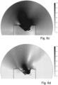
- FIGS. 6a to 6f present simulations of sound wave propagation of the embodiment of the figure 3 .
- the entire surface of the membrane 14 is used to generate the sound waves and the front face Fa of the waveguide 20 is sufficient to guide the sound waves towards the ceiling 41.
- the second acoustic wall 26 captures part of the sound waves generated by the loudspeaker 11 to redirect them towards the ceiling 41.
- the generation of sound waves is very localized in the center of the membrane 14.
- the second acoustic wall 26 becomes inoperative and it is the first acoustic wall 25 which allows the acoustic waves to be guided towards the ceiling 41.
- the sound waves are generated from the level of the inverted dome of the loudspeaker 11.
- the semi-circular lip 27 of the first acoustic wall 25 makes it possible to channel the sound waves onto the first acoustic wall 25 in order to transmit them towards the ceiling 41.
- the invention proposes to modify a waveguide 20 of a reverberation sound diffusion enclosure 10 to improve crosstalk.
- This improvement in crosstalk makes it possible to reduce the angle of inclination ⁇ 1 of the loudspeaker 11 and, thus, to place the speaker 10 further from the audience to reduce the constraints of implantation of the speaker 10. It follows that the invention makes it possible to more easily form a home cinema or a music listening room.
Landscapes
- Engineering & Computer Science (AREA)
- Physics & Mathematics (AREA)
- Acoustics & Sound (AREA)
- Signal Processing (AREA)
- Health & Medical Sciences (AREA)
- Otolaryngology (AREA)
- Multimedia (AREA)
- Obtaining Desirable Characteristics In Audible-Bandwidth Transducers (AREA)
- Details Of Audible-Bandwidth Transducers (AREA)
Claims (9)
- Lautsprecherbox (10) zur Schallausbreitung durch Nachhall, die Folgendes umfasst:- einen Lautsprecher (11) mit:. einem festen Rahmen (12),. einem zylindrischen Träger (13), der translatorisch beweglich ist, und. einer Membran (14), deren ringförmiger Außenrand (15) über eine Aufhängung (17) mit einer oberen Auflagefläche (16) des Rahmens (12) verbunden ist, und deren ringförmiger Innenrand (18) an dem zylindrischen Träger (13) befestigt ist; und- einen Wellenleiter (20), der an der oberen Auflagefläche (16) des Rahmens (12) angebracht ist, wobei der Wellenleiter im Wesentlichen die Form eines Pyramidenstumpfes mit einer langen Wand (21), einer kurzen Wand (22) und Seitenstützen (23), die die Wände (21-22) verbinden, aufweist;wobei die lange Wand (21) eine Vorderseite (Fa) der Box (10) bildet, so dass die lange Wand (21) die Ausbreitung des Schalls vor der Box (10) blockiert, damit der größte Teil des Schalls in Richtung einer Reflexionsfläche (41) geleitet wird;dadurch gekennzeichnet, dass der Wellenleiter (20) auch mindestens eine Akustikwand (25) aufweist, die an den seitlichen Stützen (23) befestigt ist, wobei die Akustikwand (25) tangential zur erzeugenden Geraden (Dg) des zylindrischen Trägers (13) verläuft, die der Vorderseite (Fa) am nächsten liegt.
- Lautsprecherbox zur Schallausbreitung durch Nachhall nach Anspruch 1, wobei der Wellenleiter (20) auch eine zweite Akustikwand (26) umfasst, die zwischen den seitlichen Stützen (23) und der ersten Akustikwand (25), die tangential zu der erzeugenden Geraden (Dg) verläuft, und der Vorderseite (Fa) befestigt ist, wobei sich die zweite Akustikwand (26) im Wesentlichen parallel zur ersten Akustikwand (25) mit einem Abstand (D1) zwischen den akustischen Wänden (25-26) verläuft, der im Wesentlichen gleich dem Radius (R) des zylindrischen Trägers (13) ist.
- Lautsprecherbox zur Schallausbreitung durch Nachhall nach Anspruch 1 oder 2, wobei die Akustikwand (25), die tangential zur erzeugenden Geraden (Dg) verläuft, eine halbkreisförmige Lippe (27) aufweist, die sich in Richtung des zylindrischen Trägers (13) im Wesentlichen in der Mitte der seitlichen Stützen (23) erstreckt.
- Lautsprecherbox zur Schallausbreitung durch Nachhall nach Anspruch 1 bis 3, wobei die Box (10) ein Gehäuse (30) aufweist, in das der Lautsprecher (11) und der Wellenleiter (20) integriert sind, wobei das Gehäuse (30) eine Höhe (H) von weniger als 14 cm, eine Länge von weniger als 28 cm und eine Breite von weniger als 18 cm aufweist.
- Lautsprecherbox zur Schallausbreitung durch Nachhall nach Anspruch 4, wobei der Lautsprecher (11) in einem Winkel (α1) zwischen 40 und 60° in Bezug auf eine Länge des Gehäuses (30) geneigt ist.
- Lautsprecherbox zur Schallausbreitung durch Nachhall nach Anspruch 1 bis 5, wobei eine obere Fläche (28) des zylindrischen Trägers (13) mit einer Kuppel versehen ist.
- Lautsprecherbox zur Schallausbreitung durch Nachhall nach Anspruch 6, wobei die Kuppel invertiert ist.
- Lautsprecherbox zur Schallausbreitung durch Nachhall nach Anspruch 1 bis 7, wobei der Lautsprecher (11) eine Membran (14) mit einem Durchmesser zwischen 5 und 15 cm aufweist.
- Heimkinoanlage mit einer Lautsprecherbox zur Schallausbreitung durch Nachhall nach einem der Ansprüche 1 bis 8.
Applications Claiming Priority (2)
| Application Number | Priority Date | Filing Date | Title |
|---|---|---|---|
| FR1915555A FR3105692B1 (fr) | 2019-12-24 | 2019-12-24 | Enceinte de diffusion de son par reverberation |
| PCT/FR2020/052576 WO2021130441A1 (fr) | 2019-12-24 | 2020-12-21 | Enceinte de diffusion de son par reverberation |
Publications (3)
| Publication Number | Publication Date |
|---|---|
| EP4082222A1 EP4082222A1 (de) | 2022-11-02 |
| EP4082222B1 true EP4082222B1 (de) | 2024-11-20 |
| EP4082222C0 EP4082222C0 (de) | 2024-11-20 |
Family
ID=70738660
Family Applications (1)
| Application Number | Title | Priority Date | Filing Date |
|---|---|---|---|
| EP20851218.6A Active EP4082222B1 (de) | 2019-12-24 | 2020-12-21 | Gehäuse zur schalldämpfung durch nachhall |
Country Status (5)
| Country | Link |
|---|---|
| US (1) | US11627411B2 (de) |
| EP (1) | EP4082222B1 (de) |
| CN (1) | CN114930872B (de) |
| FR (1) | FR3105692B1 (de) |
| WO (1) | WO2021130441A1 (de) |
Families Citing this family (1)
| Publication number | Priority date | Publication date | Assignee | Title |
|---|---|---|---|---|
| FR3167514A1 (fr) | 2024-10-16 | 2026-04-17 | Focal Jmlab | Enceinte de diffusion de son par reflexion, procede de generation de son spatialise et installation de cinema a domicile associes |
Family Cites Families (11)
| Publication number | Priority date | Publication date | Assignee | Title |
|---|---|---|---|---|
| US6343133B1 (en) * | 1999-07-22 | 2002-01-29 | Alan Brock Adamson | Axially propagating mid and high frequency loudspeaker systems |
| ITBS20010073A1 (it) * | 2001-10-03 | 2003-04-03 | Outline Di Noselli G & C S N C | Altoparlante a guida d'onda a dispersione controllata e regolabile |
| US7802650B2 (en) * | 2008-07-09 | 2010-09-28 | John Kevin Bartlett | Combination midrange and high frequency horn |
| ITRM20120086A1 (it) * | 2012-03-08 | 2013-09-09 | Emanuele Basile | Sistema di regolazione meccanica per orientazione faschio sonoro sal steering acuostic lent |
| WO2014036085A1 (en) * | 2012-08-31 | 2014-03-06 | Dolby Laboratories Licensing Corporation | Reflected sound rendering for object-based audio |
| WO2014144968A1 (en) * | 2013-03-15 | 2014-09-18 | O'polka Richard | Portable sound system |
| EP3092819A1 (de) * | 2014-01-10 | 2016-11-16 | Dolby Laboratories Licensing Corporation | Reflektierte tonwiedergabe mit abwärts abfeuernden treibern |
| US9392358B2 (en) * | 2014-10-28 | 2016-07-12 | Robert Bosch Gmbh | Waveguide for shaping sound waves |
| EP3335433B1 (de) * | 2015-08-14 | 2023-05-31 | Dolby Laboratories Licensing Corporation | Nach oben abstrahlender lautsprecher mit asymmetrischer dispersion zum erzeugen von schallreflexionen |
| US10785560B2 (en) * | 2016-05-09 | 2020-09-22 | Samsung Electronics Co., Ltd. | Waveguide for a height channel in a speaker |
| US11564032B2 (en) * | 2021-04-30 | 2023-01-24 | Harman International Industries, Incorporated | Speaker system with asymmetrical coverage horn |
-
2019
- 2019-12-24 FR FR1915555A patent/FR3105692B1/fr active Active
-
2020
- 2020-12-21 EP EP20851218.6A patent/EP4082222B1/de active Active
- 2020-12-21 US US17/787,374 patent/US11627411B2/en active Active
- 2020-12-21 WO PCT/FR2020/052576 patent/WO2021130441A1/fr not_active Ceased
- 2020-12-21 CN CN202080090030.XA patent/CN114930872B/zh active Active
Also Published As
| Publication number | Publication date |
|---|---|
| CN114930872A (zh) | 2022-08-19 |
| CN114930872B (zh) | 2023-04-04 |
| EP4082222C0 (de) | 2024-11-20 |
| US11627411B2 (en) | 2023-04-11 |
| US20230044069A1 (en) | 2023-02-09 |
| FR3105692A1 (fr) | 2021-06-25 |
| WO2021130441A1 (fr) | 2021-07-01 |
| FR3105692B1 (fr) | 2022-01-14 |
| EP4082222A1 (de) | 2022-11-02 |
Similar Documents
| Publication | Publication Date | Title |
|---|---|---|
| KR101067386B1 (ko) | 스피커 시스템 | |
| FR2875367A1 (fr) | Systeme de sonorisation directivite reglable | |
| FR2827731A1 (fr) | Haut-parleur a radiation directe et rayonnement optimise | |
| FR2679095A1 (fr) | Systeme de haut-parleurs avec traitement d'onde acoustique reproduite. | |
| FR2919454A1 (fr) | Systeme de reproduction sonore a enceinte a events. | |
| EP4082222B1 (de) | Gehäuse zur schalldämpfung durch nachhall | |
| EP0553239A1 (de) | Verfahren zur verbesserung der wiedergabequalität eines schallfeldes und gerät zu dessen durchführung unter verwendung mindestens eines in drei richtungen abstrahlenden lautsprechers | |
| FR2627341A1 (fr) | Perfectionnements aux enceintes acoustiques | |
| EP1728409B1 (de) | Mit einer geometrischen und elektronischen schallabstrahlsteuerung ausgestattete schalleinrichtung | |
| WO2022024061A1 (en) | Line source loudspeaker device | |
| KR20020035091A (ko) | 음향 에너지를 제분배하기 위한 장치 | |
| EP3063949B1 (de) | Lautsprechergehäuse mit mindestens einem lautsprecher mit einer konvexen mobilen membran mit formkontinuität mit einem angrenzenden element | |
| CN216752072U (zh) | 一种同轴喇叭与高音号角组合的线性阵列音箱 | |
| EP4664923A1 (de) | Akustische horn für gehäuse mit gekrümmten oberflächen | |
| FR3128810A1 (fr) | Mobilier à diffusion acoustique corrigée | |
| EP0649269A1 (de) | Lautsprechergehäuse mit erweiterter Diffusion | |
| FR3167514A1 (fr) | Enceinte de diffusion de son par reflexion, procede de generation de son spatialise et installation de cinema a domicile associes | |
| HK40074871A (en) | Enclosure for diffusing sound by reverberation | |
| HK40074871B (en) | Enclosure for diffusing sound by reverberation | |
| BE433174A (de) | ||
| FR2655507A1 (fr) | Haut-parleur a pavillon. | |
| FR2826827A1 (fr) | Systeme acoustique hybride | |
| WO2025248185A1 (fr) | Système de conversion électro-acoustique directif et réseau de systèmes de conversion électro-acoustique comportant un tel système | |
| FR2913846A1 (fr) | Procede de charge aerodynamique d'un haut-parleur et dispositif de reproduction sonore faisant application | |
| FR2994046A1 (fr) | Dispositif de sonorisation a pavillon et reflecteur confondus |
Legal Events
| Date | Code | Title | Description |
|---|---|---|---|
| STAA | Information on the status of an ep patent application or granted ep patent |
Free format text: STATUS: UNKNOWN |
|
| STAA | Information on the status of an ep patent application or granted ep patent |
Free format text: STATUS: THE INTERNATIONAL PUBLICATION HAS BEEN MADE |
|
| PUAI | Public reference made under article 153(3) epc to a published international application that has entered the european phase |
Free format text: ORIGINAL CODE: 0009012 |
|
| STAA | Information on the status of an ep patent application or granted ep patent |
Free format text: STATUS: REQUEST FOR EXAMINATION WAS MADE |
|
| 17P | Request for examination filed |
Effective date: 20220623 |
|
| AK | Designated contracting states |
Kind code of ref document: A1 Designated state(s): AL AT BE BG CH CY CZ DE DK EE ES FI FR GB GR HR HU IE IS IT LI LT LU LV MC MK MT NL NO PL PT RO RS SE SI SK SM TR |
|
| DAV | Request for validation of the european patent (deleted) | ||
| DAX | Request for extension of the european patent (deleted) | ||
| GRAP | Despatch of communication of intention to grant a patent |
Free format text: ORIGINAL CODE: EPIDOSNIGR1 |
|
| STAA | Information on the status of an ep patent application or granted ep patent |
Free format text: STATUS: GRANT OF PATENT IS INTENDED |
|
| INTG | Intention to grant announced |
Effective date: 20240725 |
|
| GRAS | Grant fee paid |
Free format text: ORIGINAL CODE: EPIDOSNIGR3 |
|
| GRAA | (expected) grant |
Free format text: ORIGINAL CODE: 0009210 |
|
| STAA | Information on the status of an ep patent application or granted ep patent |
Free format text: STATUS: THE PATENT HAS BEEN GRANTED |
|
| AK | Designated contracting states |
Kind code of ref document: B1 Designated state(s): AL AT BE BG CH CY CZ DE DK EE ES FI FR GB GR HR HU IE IS IT LI LT LU LV MC MK MT NL NO PL PT RO RS SE SI SK SM TR |
|
| RAP3 | Party data changed (applicant data changed or rights of an application transferred) |
Owner name: FOCAL JMLAB |
|
| REG | Reference to a national code |
Ref country code: GB Ref legal event code: FG4D Free format text: NOT ENGLISH |
|
| REG | Reference to a national code |
Ref country code: CH Ref legal event code: EP |
|
| REG | Reference to a national code |
Ref country code: DE Ref legal event code: R096 Ref document number: 602020041819 Country of ref document: DE |
|
| REG | Reference to a national code |
Ref country code: IE Ref legal event code: FG4D Free format text: LANGUAGE OF EP DOCUMENT: FRENCH |
|
| U01 | Request for unitary effect filed |
Effective date: 20241120 |
|
| U07 | Unitary effect registered |
Designated state(s): AT BE BG DE DK EE FI FR IT LT LU LV MT NL PT RO SE SI Effective date: 20241126 |
|
| U20 | Renewal fee for the european patent with unitary effect paid |
Year of fee payment: 5 Effective date: 20241230 |
|
| PG25 | Lapsed in a contracting state [announced via postgrant information from national office to epo] |
Ref country code: HR Free format text: LAPSE BECAUSE OF FAILURE TO SUBMIT A TRANSLATION OF THE DESCRIPTION OR TO PAY THE FEE WITHIN THE PRESCRIBED TIME-LIMIT Effective date: 20241120 Ref country code: IS Free format text: LAPSE BECAUSE OF FAILURE TO SUBMIT A TRANSLATION OF THE DESCRIPTION OR TO PAY THE FEE WITHIN THE PRESCRIBED TIME-LIMIT Effective date: 20250320 |
|
| PG25 | Lapsed in a contracting state [announced via postgrant information from national office to epo] |
Ref country code: ES Free format text: LAPSE BECAUSE OF FAILURE TO SUBMIT A TRANSLATION OF THE DESCRIPTION OR TO PAY THE FEE WITHIN THE PRESCRIBED TIME-LIMIT Effective date: 20241120 |
|
| PG25 | Lapsed in a contracting state [announced via postgrant information from national office to epo] |
Ref country code: NO Free format text: LAPSE BECAUSE OF FAILURE TO SUBMIT A TRANSLATION OF THE DESCRIPTION OR TO PAY THE FEE WITHIN THE PRESCRIBED TIME-LIMIT Effective date: 20250220 |
|
| PG25 | Lapsed in a contracting state [announced via postgrant information from national office to epo] |
Ref country code: GR Free format text: LAPSE BECAUSE OF FAILURE TO SUBMIT A TRANSLATION OF THE DESCRIPTION OR TO PAY THE FEE WITHIN THE PRESCRIBED TIME-LIMIT Effective date: 20250221 |
|
| PG25 | Lapsed in a contracting state [announced via postgrant information from national office to epo] |
Ref country code: PL Free format text: LAPSE BECAUSE OF FAILURE TO SUBMIT A TRANSLATION OF THE DESCRIPTION OR TO PAY THE FEE WITHIN THE PRESCRIBED TIME-LIMIT Effective date: 20241120 |
|
| PG25 | Lapsed in a contracting state [announced via postgrant information from national office to epo] |
Ref country code: RS Free format text: LAPSE BECAUSE OF FAILURE TO SUBMIT A TRANSLATION OF THE DESCRIPTION OR TO PAY THE FEE WITHIN THE PRESCRIBED TIME-LIMIT Effective date: 20250220 |
|
| PG25 | Lapsed in a contracting state [announced via postgrant information from national office to epo] |
Ref country code: SM Free format text: LAPSE BECAUSE OF FAILURE TO SUBMIT A TRANSLATION OF THE DESCRIPTION OR TO PAY THE FEE WITHIN THE PRESCRIBED TIME-LIMIT Effective date: 20241120 |
|
| PG25 | Lapsed in a contracting state [announced via postgrant information from national office to epo] |
Ref country code: SK Free format text: LAPSE BECAUSE OF FAILURE TO SUBMIT A TRANSLATION OF THE DESCRIPTION OR TO PAY THE FEE WITHIN THE PRESCRIBED TIME-LIMIT Effective date: 20241120 |
|
| PG25 | Lapsed in a contracting state [announced via postgrant information from national office to epo] |
Ref country code: CZ Free format text: LAPSE BECAUSE OF FAILURE TO SUBMIT A TRANSLATION OF THE DESCRIPTION OR TO PAY THE FEE WITHIN THE PRESCRIBED TIME-LIMIT Effective date: 20241120 |
|
| REG | Reference to a national code |
Ref country code: CH Ref legal event code: PL |
|
| PG25 | Lapsed in a contracting state [announced via postgrant information from national office to epo] |
Ref country code: MC Free format text: LAPSE BECAUSE OF FAILURE TO SUBMIT A TRANSLATION OF THE DESCRIPTION OR TO PAY THE FEE WITHIN THE PRESCRIBED TIME-LIMIT Effective date: 20241120 |
|
| PLBE | No opposition filed within time limit |
Free format text: ORIGINAL CODE: 0009261 |
|
| STAA | Information on the status of an ep patent application or granted ep patent |
Free format text: STATUS: NO OPPOSITION FILED WITHIN TIME LIMIT |
|
| PG25 | Lapsed in a contracting state [announced via postgrant information from national office to epo] |
Ref country code: CH Free format text: LAPSE BECAUSE OF NON-PAYMENT OF DUE FEES Effective date: 20241231 |
|
| 26N | No opposition filed |
Effective date: 20250821 |
|
| PG25 | Lapsed in a contracting state [announced via postgrant information from national office to epo] |
Ref country code: IE Free format text: LAPSE BECAUSE OF NON-PAYMENT OF DUE FEES Effective date: 20241221 |
|
| PGFP | Annual fee paid to national office [announced via postgrant information from national office to epo] |
Ref country code: GB Payment date: 20251229 Year of fee payment: 6 |
|
| U20 | Renewal fee for the european patent with unitary effect paid |
Year of fee payment: 6 Effective date: 20251229 |