EP4082033B1 - Schaltvorrichtung mit schliessverhinderung - Google Patents
Schaltvorrichtung mit schliessverhinderung Download PDFInfo
- Publication number
- EP4082033B1 EP4082033B1 EP20841657.8A EP20841657A EP4082033B1 EP 4082033 B1 EP4082033 B1 EP 4082033B1 EP 20841657 A EP20841657 A EP 20841657A EP 4082033 B1 EP4082033 B1 EP 4082033B1
- Authority
- EP
- European Patent Office
- Prior art keywords
- moveable contact
- fully open
- open position
- moveable
- opening
- Prior art date
- Legal status (The legal status is an assumption and is not a legal conclusion. Google has not performed a legal analysis and makes no representation as to the accuracy of the status listed.)
- Active
Links
Images







Classifications
-
- H—ELECTRICITY
- H01—ELECTRIC ELEMENTS
- H01H—ELECTRIC SWITCHES; RELAYS; SELECTORS; EMERGENCY PROTECTIVE DEVICES
- H01H71/00—Details of the protective switches or relays covered by groups H01H73/00 - H01H83/00
- H01H71/04—Means for indicating condition of the switching device
-
- H—ELECTRICITY
- H01—ELECTRIC ELEMENTS
- H01H—ELECTRIC SWITCHES; RELAYS; SELECTORS; EMERGENCY PROTECTIVE DEVICES
- H01H3/00—Mechanisms for operating contacts
- H01H3/32—Driving mechanisms, i.e. for transmitting driving force to the contacts
-
- H—ELECTRICITY
- H01—ELECTRIC ELEMENTS
- H01H—ELECTRIC SWITCHES; RELAYS; SELECTORS; EMERGENCY PROTECTIVE DEVICES
- H01H71/00—Details of the protective switches or relays covered by groups H01H73/00 - H01H83/00
- H01H71/10—Operating or release mechanisms
- H01H71/12—Automatic release mechanisms with or without manual release
- H01H71/46—Automatic release mechanisms with or without manual release having means for operating auxiliary contacts additional to the main contacts
-
- H—ELECTRICITY
- H01—ELECTRIC ELEMENTS
- H01H—ELECTRIC SWITCHES; RELAYS; SELECTORS; EMERGENCY PROTECTIVE DEVICES
- H01H71/00—Details of the protective switches or relays covered by groups H01H73/00 - H01H83/00
- H01H71/10—Operating or release mechanisms
- H01H71/50—Manual reset mechanisms which may be also used for manual release
- H01H71/52—Manual reset mechanisms which may be also used for manual release actuated by lever
- H01H71/522—Manual reset mechanisms which may be also used for manual release actuated by lever comprising a cradle-mechanism
- H01H71/525—Manual reset mechanisms which may be also used for manual release actuated by lever comprising a cradle-mechanism comprising a toggle between cradle and contact arm and mechanism spring acting between handle and toggle knee
-
- H—ELECTRICITY
- H01—ELECTRIC ELEMENTS
- H01H—ELECTRIC SWITCHES; RELAYS; SELECTORS; EMERGENCY PROTECTIVE DEVICES
- H01H9/00—Details of switching devices, not covered by groups H01H1/00 - H01H7/00
- H01H9/20—Interlocking, locking, or latching mechanisms
-
- H—ELECTRICITY
- H01—ELECTRIC ELEMENTS
- H01H—ELECTRIC SWITCHES; RELAYS; SELECTORS; EMERGENCY PROTECTIVE DEVICES
- H01H71/00—Details of the protective switches or relays covered by groups H01H73/00 - H01H83/00
- H01H71/04—Means for indicating condition of the switching device
- H01H2071/042—Means for indicating condition of the switching device with different indications for different conditions, e.g. contact position, overload, short circuit or earth leakage
-
- H—ELECTRICITY
- H01—ELECTRIC ELEMENTS
- H01H—ELECTRIC SWITCHES; RELAYS; SELECTORS; EMERGENCY PROTECTIVE DEVICES
- H01H2235/00—Springs
- H01H2235/01—Spiral spring
Definitions
- This disclosure generally relates to electrical switching devices such as circuit breakers. More particularly, this disclosure describes a switching device having an improved design to help prevent the device's switch from closing if closure would cause an unsafe condition.
- a self-contained switching device such as a circuit breaker with an electronic trip unit (ETU)
- ETU electronic trip unit
- features are sometimes added to prevent closing the device and completing the primary circuit.
- These are often user-configurable features of the ETU that protect against closure if the closure would cause an unsafe condition.
- a simple example of an unsafe condition is a ground fault or other overcurrent condition.
- closing the system's tie breaker when the sources are not well-matched in voltage, frequency or phase could cause damage to system components. If the tie breaker's ETU detects such a mismatch, or if a remote controller that is monitoring the system detects the mismatch, the ETU or remote controller may respond by blocking any attempts to close the tie breaker.
- Configurations in which the ETU or remote controller prevents closing are effective when the close command is initiated electronically, such as by a remote or local electrical actuator.
- the system's programming may prioritize a "block closure" command over a command to close the switch.
- Such configurations are not effective to block closure when closure is initiated locally by physical action, such as by an operator who depresses a mechanical pushbutton to manually operate the switch. This ineffectiveness occurs because electronic logic cannot intervene in the direct mechanical actuation of the circuit breaker mechanism.
- the circuit breaker's ETU would need to operate the trip actuator and override the closing attempt, but trip actuators are typically intermittent operation devices and are not always maintained in an active state.
- the trip actuators of some circuit breakers cannot mechanically operate to stop a close attempt when the circuit breaker is open. This is because the circuit breaker mechanism holds the trip actuator mechanism in the reset position whenever the switch is open. Further, ETUs of prior art circuit breakers typically will not detect when closure starts, but instead will only detect when the breaker's contacts touch, at which point it will have been too late to prevent the closure from happening. Even a few milliseconds of closure could damage system components and/or create safety hazards in overcurrent or voltage mismatch conditions.
- This document describes an improved switching mechanism that is designed to help prevent closure of a switching device, even if the closure is initiated manually, when closure could result in an unsafe condition.
- EP 2 001 032 A1 there is disclosed a cercuit breaker as it is defined in the pre-characterizing portion of claim 1.
- a circuit breaker in various embodiments, includes a moveable contact, an opening spring that is operably connected to the moveable contact, and a sensor that operates as a full open sensor.
- the sensor exhibits a first output condition when the moveable contact is in a fully open position, and it exhibits a second output condition when the moveable contact leaves the fully open position.
- An electronic trip unit (ETU) is electrically connected to the sensor and, when in a close break mode, blocks the circuit breaker from closing. The ETU does this by, in response to detecting that the sensor is in the second output condition (which corresponds to the moveable contact leaving the fully open position), generating a signal that will cause the opening spring to return the moveable contact to the fully open position.
- the circuit breaker includes a trip actuator.
- the circuit breaker also includes an opening latch that, when in a latched position, will hold a linkage in a position which allows closing, and which thus holds the opening spring in a loaded position.
- the ETU's signal may cause the trip actuator to release the opening latch. Releasing the opening latch will allow the linkage to move and permit the opening spring to return to an unloaded condition.
- the trip actuator may include a plunger having a retracted position and an extended position. The extended position may be operably connected to the opening latch. When the trip actuator receives the signal from ETU, the trip actuator will cause the plunger to move from the retracted position to the extended position and thus release the opening latch.
- the trip actuator will be reset.
- the circuit breaker includes a moveable arm that is operably connected to the moveable contact, and may include axle that is operably and rotatably connected to the moveable arm.
- the circuit breaker also may include a linkage that operably connects the opening spring with the moveable arm via the axle, along with an extended member (such as a cam) that is connected to the axle.
- the sensor may be positioned to detect the extended member when a position of the moveable contact corresponds to the fully open position. Alternatively, the sensor may be configured to detect a rotational position of the axle.
- Other embodiments are directed to a method of operating a circuit breaker that has a moveable contact, an opening spring, a sensor and an ETU.
- the method includes, by the sensor, detecting that the moveable contact is in a fully open position. After the sensor initially detects that the moveable contact is in the fully open position, the sensor may detect that the moveable contact has moved away from the fully open position. When this happens, then in response the sensor will change from a first output condition to a second output condition (such as from off to on, or from on to off). When the ETU detects that the sensor has changed to the second output condition, then in response it will cause the opening spring to return the moveable contact to the fully open position.
- the circuit breaker also includes an opening latch that is operably connected to the opening spring. Causing the opening spring to return the moveable contact to the fully open position may be effected as the ETU causes the opening latch to release, which in turn causes the opening spring to relax (i.e., return to an unloaded condition).
- the opening spring may be operably connected to a lever that is operably connected to an axle, and the moveable contact is operably connected to a moveable arm that is also operably connected to the axle. In such a case, causing the opening spring to retract to the unextended condition may turn the axle, turning the axle rotates the moveable arm, and rotating the moveable arm moves the moveable contact to the fully open position.
- the axle may include an extended member (such as a cam).
- Detecting that the moveable contact is in the fully open position may include detecting, by the sensor that the extended member has moved away from the sensor or that the extended member has moved over the sensor.
- Other sensors such as a sensor that detects rotational position of the axle may be used to detect whether the moveable contact has left the fully open position.
- the circuit breaker also includes a trip actuator that includes a plunger having a retracted position and an extended position.
- the trip actuator may be operably connected to the opening latch when in the extended position. If so, then in the method, causing the opening latch to release may include, by the ETU, generating a signal causes the trip actuator to release the opening latch by extending the plunger from the retracted position to the extended position.
- the moveable contact may be connected to a moveable arm; and returning the moveable contact to the fully open position may cause the plunger to move to the retracted position and reset the trip actuator.
- the circuit breaker also includes a closing spring. Detecting that the moveable contact has moved away from the fully open position occurs in response to the closing spring generating a closing force that begins to move the movable contact toward a closed position. When the opening spring returns the moveable contact to the fully open position, the opening spring will do so after the release of the opening latch, which releases the linkage that connects the closing spring to the movable arm.
- a stored energy circuit breaker includes a moveable contact, and a sensor.
- the sensor is positioned to exhibit a first output condition when the moveable contact is in a fully open position, and to exhibit a second output condition when the moveable contact moves away from the fully open position.
- the circuit breaker also may include an extended member that is positioned over the sensor which the moveable contact is in the fully open position, and that is not positioned over the sensor when the moveable contact leaves the fully open position.
- the extended member may be positioned over the sensor when the moveable contact is in any position other than the fully open position.
- Other methods of sensing the full open position may include continuous position sensors in place of the extended member interacting with a discrete sensor.
- the circuit breaker includes an ETU that is electrically connected to the sensor and that is configured to, in response to detecting that the sensor is in the second output condition, cause the moveable contact to return to the fully open position.
- the circuit breaker also may include a trip actuator that is electrically connected to the electronic trip unit and that is configured to receive and implement a command to cause the moveable contact to return to the fully open position.
- the circuit breaker also may include an opening latch that is operably connected to the trip actuator.
- the circuit breaker also may include an opening spring that is operably connected to the opening latch and to the moveable contact. The opening latch may: (i) when latched, hold the opening spring in a loaded position; and (ii) when unlatched, permit the opening spring to return to an unloaded position.
- This disclosure describes a circuit breaker that incorporates a full open sensor that is used to help prevent closure of the breaker in conditions in which a closure could create an unsafe condition.
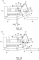
- FIGs. 1A-1E are block diagrams that illustrate certain components of a stored energy circuit breaker 100 such as may exist in the prior art.
- the circuit breaker is operable to make or break a circuit between a first conductor 101 and a second conductor 102 .
- the first conductor 101 is electrically connected to a moveable conductive arm 107 that includes a moveable contact 103
- the second conductor 102 (which may be a fixed conductive arm) is electrically connected to a fixed contact 104
- the fixed contact 104 may be a conductive element that is electrically connected to the second conductor 102 , or the fixed contact 104 may simply be an area of the second conductor 102 that will touch the moveable contact 103 when the circuit breaker 100 is in a closed position.
- FIGs. 1A - 1ED illustrate these and other components of such a prior art circuit breaker at various stages of operation, moving from an open position to a closed position.
- the closing spring 111 may be a compression spring as illustrated by the arrows illustrating a direction of compression force
- the opening spring 121 may be a tension spring as illustrated by the arrows showing a direction of expansion.
- this arrangement may be reversed, or both springs may be of the same type, or other springs may be used such as torsion springs.
- FIG. 1A illustrates the breaker in an open position, ready to close in that the closing spring 111 is mechanically charged, such as by a motor or by human operation, and is held in its compressed position by a closing latch 112 .
- FIG. 1B illustrates that the closing spring 111 decompresses (i.e., relaxes) and begins to directly or indirectly push against one or more elements of the mechanical linkage (i.e., elements 105a and/or 105b) that are operably connected to the moveable arm 107 .
- Another element of the mechanical linkage 105c is held fixed by an opening latch 122 .
- FIG. 1C illustrates that as the closing spring 111 further decompresses and pushes against the mechanical linkage elements 105a, 105b, the mechanical linkage elements 105a, 105b move the moveable arm 107 downward, which forces the moveable contact 103 toward the fixed contact 104.
- the moveable contact 103 reaches and touches the fixed contact 104, the mechanical linkage elements 105a, 105b have reached a stop position (illustrated by dot 109) , and the circuit is closed.
- the closing spring 111 is fully discharged.
- the opening spring 121 has been stretched and is therefore charged.
- the opening latch 122 holds the links 105a, 105b of the mechanical linkage in the stop position 109 and keep the opening spring 121 in an outstretched position.
- the opening latch 122 may be moved to this position manually by a mechanical push-button, remotely by a solenoid, or by the trip actuator 141 .
- the closing spring 111 will be recharged (in this example, compressed), either automatically by motor activation or manually by operation of a compression mechanism, and the closing latch 112 will be moved to hold the closing spring 111 in the charged position while the links 105a, 105b of the mechanical linkage remain in the stop position 109 .
- This final position is shown in FIG. 1E .
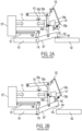
- FIGs. 2A- 2C are block diagrams that illustrate components of the previously-described prior art circuit breaker as it moves from a closed position to a fully open position.
- the circuit breaker begins to open as the trip actuator 141 is operated.
- the trip actuator 141 may include a magnetic latch that is released with an electrical pulse from the circuit breaker's electronic trip unit (ETU).
- ETU electronic trip unit
- the plunger 142 of the trip actuator 141 may extend and drive a trip linkage 135a, 135b to move and release the opening latch 122, which releases the opening spring 121 and allows it to recoil to its naturally retracted (i.e., relaxed) position.
- Releasing the opening latch 122 also removes constraints on the linkage elements 105a, 105b and 105c and decouples the closing spring 111 from the linkage elements 105a and 105b .
- the force of closing spring 111 may then be transferred to linkage element 105c , which can now move since the opening latch 122 is released. This allows linkage elements 105a and 105b to then move away from the stop position and allow this retraction of the opening spring 121 .
- the opening spring 121 relaxes (in this example, expands toward the open position), it directly or indirectly moves a contact linkage 108 that rotates the axle 119 , which is rotatably connected to the moveable arm 107 and thus causes the moveable arm 107 to rotate, which pulls the moveable contact 103 away from the fixed contact 104 .
- the closing spring 111 has not yet been recharged. However, this is merely an example. Recharging of the closing spring may occur before or after the opening operation of FIGs. 2A-2C .
- FIG. 2B As the opening spring 121 continues to relax (i.e., unload), it continues to move the linkage 108 , which rotates the moveable arm 107 about the axle 119 and pulls the moveable contact 103 further away from the fixed contact 104 and toward a drive element 135b of the trip linkage.
- the drive element 135b is the section of the trip linkage that the trip actuator's plunger 142 previously pushed downward. Pulling the linkage 108 to the left in FIGs. 2A-2C rotates the axle 119 , which rotates the moveable arm 107 and causes the free end of the moveable contact 103 to move upward.
- the moveable contact 103 has moved into the fully open position and directly or indirectly caused the drive element 135b of the trip linkage to move up to reset the plunger 142 into the trip actuator 141 .
- the closing spring 111 may be recharged by motor-driven or manual operation to end up in the position originally shown above in FIG. 1A .
- the opening latch 122 will also be moved to latch the breaker in the open position in preparation for the next closing operation as shown in FIG. 1A .
- the close latch 112 receives a command to release from a controller, the command can be overridden by circuitry or programming logic so that the close latch does not in fact release in certain conditions.
- prior art systems are not capable of stopping manual operation of the close latch.
- this disclosure proposes an enhanced close block method and mechanism in which the circuit breaker includes a full open sensor 452 that is electrically connected to the electronic trip unit (ETU) 451 .
- the ETU 451 may be a conventional ETU or a customized ETU.
- the ETU may be a programmable device such as a processor that receives signals from one or more external components and uses those signals to determine whether to trip the trip actuator 142 .
- the term ETU also may refer to an electromechanical trip unit that includes current-sensitive and thermal-sensitive devices that determine when to actuate the trip actuator 142 and open the breaker.
- the circuit breaker also may include a full close sensor 453 . As shown in FIG. 4 , the full open sensor 452 and full close sensor 453 may be switches, pressure sensitive or other sensors positioned near the axle 119 to which the moveable arm 107 is operably connected.
- the axle 119 may be equipped with a rotatable extended member such as a pin, lever or cam 401 that is positioned to be detected by, and thus change the condition of (i.e., turn on or turn off), the full open sensor 452 when the shaft position rotates to the circuit breaker's fully-open position. It may change the condition of the full close sensor 453 when the axle 119 rotates to the circuit breaker's fully-closed position.
- the extended member may be positioned over the sensor when the breaker is in the fully-open position as shown in FIG. 4 .
- the extended member may be configured so that it is always positioned over the full open sensor unless the breaker is in the fully-open position.
- a rotational position sensor 405 may detect the rotational position of the axle.
- the sensor may be a sensor that is positioned in a location where it can directly detect the location of the moveable contact, or where it may detect the length of the opening spring. Other sensor configurations are possible.
- the circuit breaker is ready to close. Under normal conditions (i.e., no detection of overcurrent, ground fault, power mismatch or other unsafe conditions) this breaker will operate according to the procedures discussed above for FIGs. 1A-1D and 2A-2C .
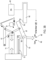
- the ETU 451 in the example of FIG. 3A is operating to require close blocking, meaning that it will block the circuit breaker from closing and keep it open.
- the ETU 451 may do this in response to, for example, a current detector detecting an overcurrent condition, a thermal sensor detecting an overheated condition, or detection of a phase mismatch across two sides of a trip breaker of a main-tie-main system. If a human attempts to manually release the closing latch 112 when the ETU is requiring close blocking, the output of the full open sensor 452 will change (such as changing from an on signal to an off signal or no signal) as shown in FIG. 3B .
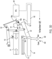
- the ETU Upon detecting this change of condition of the full open sensor 452 , as illustrated in FIG. 3C the ETU will immediately send a signal to actuate the trip actuator 141 . As illustrated in FIG. 3D this signal causes the plunger 142 of the trip actuator to extend from a retracted position (as in FIG. 3C ) to an extended position (as in FIG. 3D ), which in turn moves the trip linkage elements 135a, 135b to release the opening latch 122 . Releasing the opening latch 122 releases the tension in the opening spring 121 and causes the opening spring 121 to retract toward an unextended position.
- the release of the linkage by the opening latch will decouple the closing spring from the linkage elements 135a, 135b , allowing the opening spring to open.
- the closing spring 111 began to expand and apply a force to close the breaker, the opening spring 121 will immediately contract and pull the breaker open and prevent it from fully closing, thus maintaining a gap between the moveable contact 103 and the fixed contact 104 .
- the breaker may then return to the fully open position as shown in FIG. 3A . although the closing spring 111 will be fully discharged at this point (as shown in FIG. 2C ). At this point the moveable contact 103 will reset the trip actuator 141 , the full open switch 452 may return to delivering a full open signal to the ETU 451 , the ETU 451 may cease signaling the trip actuator 141 to actuate, and the closing spring 111 may be recharged.
- a full open switch into a stored energy (i.e., spring release) circuit breaker provides an improved closing prevention capability that can override not only an electronic signal, but also manual operation of the breaker's closing mechanism.
- the fully open sensor will actuate before the moveable contact moves halfway through its mechanical range of motion of the closing operation, and in many configurations it will actuate well before that point.
- the fully open sensor may actuate when the moveable contact reaches approximately 10% of its mechanical range of motion, approximately 20% of its mechanical range of motion, approximately 30% of its mechanical range of motion, approximately 40% of its mechanical range of motion, or some other set position.
- the moveable contact may actuate when the moveable contact reaches approximately 10% of its mechanical range of motion, approximately 20% of its mechanical range of motion, approximately 30% of its mechanical range of motion, approximately 40% of its mechanical range of motion, or some other set position.
- the ETU When the ETU detects the fully open sensor's change in signal at position 302 , the ETU will trigger the trip actuator, which releases the opening latch and causes the moveable contact to return to the fully open position at 501 rather than continue to move to positions 503 and 504 .
- connection when referring to two physical structures, means that the two physical structures touch each other.
- Devices that are connected may be secured to each other, or they may simply touch each other and not be secured.
- operably connected when referring to two physical structures, means operation (i.e., movement) of one structure will cause the other structure to responsively move.
- Operably connected structures may be physically connected to each other, or they may be indirectly connected via one or more intermediate structures.
- the term "electrically connected" when referring to two electrical components, means that a conductive path exists between the two components.
- the path may be a direct path, or an indirect path through one or more intermediary components.
- relative terms of position such as “up” and “down”, “upper” and “lower”, and “upward” and “downward” are not intended to have absolute orientations but are instead intended to describe relative positions of various components with respect to each other.
- a first component may be an “upper” component and a second component may be a “lower” component when a device of which the components are a part is oriented in a first direction.
- the relative orientations of the components may be reversed, or the components may be on the same plane, if the orientation of the structure that contains the components is changed.
- the claims are intended to include all orientations of a device containing such components.
Landscapes
- Breakers (AREA)
Claims (10)
- Leistungsschalter, umfassend:einen beweglichen Arm (107), der funktional mit einem beweglichen Kontakt (103) verbunden ist;einen festen Kontakt (104);eine Schließfeder (111), die funktional mit einer oder mehreren Verbindungen (105a, 105b) verbunden ist, die funktional mit dem beweglichen Arm (107) verbunden und konfiguriert sind, um den beweglichen Kontakt (103) auf den festen Kontakt (104) zu oder von ihm weg zu bewegen;eine Öffnungsfeder (121), die funktional mit dem beweglichen Kontakt (103) verbunden ist; undeinen Sensor (452), der funktional ist, um einen ersten Ausgabezustand aufzuweisen, wenn sich der bewegliche Kontakt (103) in einer vollständig geöffneten Position befindet, und einen zweiten Ausgabezustand, wenn der bewegliche Kontakt die vollständig geöffnete Position verlässt;gekennzeichnet durch:eine Öffnungsverriegelung (122), die in einer verriegelten Position die eine oder mehreren Verbindungen (105a, 105b) in einer Position hält, die das Schließen des beweglichen Kontakts (103) und das Erreichen einer belasteten Position der Öffnungsfeder (121) ermöglicht;ein Auslösestellglied (141), das mit einer Auslöseverbindung (135a, 135b) gekoppelt ist, und einen Kolben (142) beinhaltet, der zum Antreiben der Auslöseverbindung konfiguriert ist, wobei der Kolben eine eingefahrene und eine ausgefahrene Position aufweist, das Auslösestellglied funktional mit der Öffnungsverriegelung (122) verbunden ist, wenn sich der Kolben in der ausgefahrenen Position befindet; undeine elektronische Auslöseeinheit (451), die elektrisch mit dem Sensor (452) verbunden ist, und die konfiguriert ist, um das Schließen des Leistungsschalters zu blockieren, als Reaktion auf das Detektieren, dass sich der Sensor im zweiten Ausgabezustand befindet, der angibt, dass der bewegliche Kontakt (103) die vollständig geöffnete Position verlassen hat, ein Signal erzeugt und sendet, um das Auslösestellglied (141) sofort zu betätigen, wobei das Signal veranlasst, dass der Kolben (142) von der eingefahrenen Position in die ausgefahrene Position ausfährt und die Auslöseverbindung (135a, 135b) bewegt, um die Öffnungsverriegelung (122) zu lösen, wobei:das Lösen der Öffnungsverriegelung (122) die Spannung in der Öffnungsfeder (121) löst und veranlasst, dass die Öffnungsfeder in einen entspannten Zustand zurückkehrt,das Lösen der Öffnungsverriegelung (122) auch Beschränkungen an der einen oder den mehreren Verbindungen (105a, 105b) entfernt und die Schließfeder (111) von der einen oder den mehreren Verbindungen entkoppelt, unddas Entkoppeln der Schließfeder (111) von der einen oder den mehreren Verbindungen (105a, 105b) ermöglicht, dass die Öffnungsfeder (121) den beweglichen Arm (107) einfahren und drehen kann, um den beweglichen Kontakt in die vollständig geöffnete Position zu öffnen, wodurch ein vollständiges Schließen des beweglichen Kontakts verhindert wird.
- Leistungsschalter nach Anspruch 1, wobei der bewegliche Kontakt (103), wenn er sich in der vollständig geöffneten Position befindet, veranlasst, dass sich ein Antriebselement (135b) der Auslöseverbindung (135a, 135b) nach oben bewegt, um den Kolben (142) in das Auslösestellglied (141) zurückzusetzen.
- Leistungsschalter nach Anspruch 1, ferner umfassend:eine Achse (119), die funktional mit dem beweglichen Kontakt (103) verbunden ist;eine Verbindung (108), die die Öffnungsfeder funktional mit dem beweglichen Arm mittels der Achse verbindet.
- Leistungsschalter nach Anspruch 3, ferner umfassend:
ein ausgefahrenes Element (501), das funktional mit der Achse verbunden ist, wobei der Sensor so positioniert ist, dass er das ausgefahrene Element detektiert, wenn eine Position des beweglichen Kontakts der vollständig geöffneten Position entspricht. - Verfahren zum Betreiben eines Leistungsschalters, wobei das Verfahren umfasst:in einem Leistungsschalter, der einen beweglichen Kontakt (103), eine Öffnungsfeder (121), einen Sensor (452) und eine elektronische Auslöseeinheit (451) aufweist:durch den Sensor:Detektieren, dass sich der bewegliche Kontakt in einer vollständig geöffneten Position befindet;nach dem Detektieren, dass sich der bewegliche Kontakt in der vollständig geöffneten Position befindet;Detektieren, dass sich der bewegliche Kontakt von der vollständig geöffneten Position weg bewegt hat; undals Reaktion auf das Detektieren, dass sich der bewegliche Kontakt von der vollständig geöffneten Position weg bewegt hat, Wechseln von einem ersten Ausgabezustand in einen zweiten Ausgabezustand,durch die elektronische Auslöseeinheit:Detektieren, dass der Sensor in den zweiten Ausgabezustand gewechselt hat; undals Reaktion auf das Detektieren, dass der Sensor in den zweiten Ausgabezustand gewechselt hat, Veranlassen der Öffnungsfeder, den beweglichen Kontakt in die vollständig geöffnete Position zurückzuführen;wobei:der Leistungsschalter ferner eine Öffnungsverriegelung (122) aufweist, die funktional mit der Öffnungsfeder verbunden ist; undVeranlassen, dass die Öffnungsfeder den beweglichen Kontakt in die vollständig geöffnete Position zurückführt, wenn die elektronische Auslöseeinheit die Öffnungsverriegelung löst, was wiederum veranlasst, dass die Öffnungsfeder in einen unbelasteten Zustand zurückkehrt.
- Verfahren nach Anspruch 5, wobei:die Öffnungsfeder funktional mit einem Hebel (401) verbunden ist, der funktional mit einer Achse (119) verbunden ist;der bewegliche Kontakt funktional mit einem beweglichen Arm (107) verbunden ist, der ebenfalls funktional mit der Achse verbunden ist;Veranlassen der Öffnungsfeder, in den unbelasteten Zustand zurückzukehren, die Achse dreht;Drehen der Achse den beweglichen Arm dreht; undDrehen des beweglichen Arms den beweglichen Kontakt in die vollständig geöffnete Position bewegt.
- Verfahren nach Anspruch 6, wobei:die Achse ein ausgefahrenes Element (501) umfasst; undDetektieren, dass sich der bewegliche Kontakt in der vollständig geöffneten Position befindet, Detektieren durch den Sensor umfasst, dass sich das ausgefahrene Element vom Sensor wegbewegt hat.
- Verfahren nach Anspruch 5, wobei:der Leistungsschalter ferner ein Auslösestellglied (141) umfasst;das Auslösestellglied einen Kolben umfasst, der eine eingefahrene und eine ausgefahrene Position aufweist, und das Auslösestellglied in der ausgefahrenen Position funktional mit der Öffnungsverriegelung verbunden ist; undVeranlassen der Öffnungsverriegelung zum Lösen Erzeugen eines Signals durch die elektronische Auslöseeinheit umfasst, das das Auslösestellglied veranlasst, die Öffnungsverriegelung durch Ausfahren des Kolbens aus der eingefahrenen Position in die ausgefahrene Position zu lösen.
- Verfahren nach Anspruch 8, wobei:der bewegliche Kontakt mit einem beweglichen Arm (107) verbunden ist; undZurückkehren des beweglichen Kontakts in die vollständig geöffnete Position den Kolben veranlasst, sich in die eingefahrene Position zu bewegen und das Auslösestellglied zurücksetzt.
- Verfahren nach Anspruch 5, wobei:der Leistungsschalter ferner eine Schließfeder (111) umfasst;Detektieren, dass sich der bewegliche Kontakt von der vollständig geöffneten Position weg bewegt hat, als Reaktion darauf erfolgt, dass die Schließfeder eine Schließkraft erzeugt, die beginnt, den beweglichen Kontakt in Richtung einer geschlossenen Position zu bewegen; undVeranlassen der Öffnungsfeder, den beweglichen Kontakt in die vollständig geöffnete Position zurückzuführen, die Schließkraft entfernt.
Applications Claiming Priority (3)
| Application Number | Priority Date | Filing Date | Title |
|---|---|---|---|
| US201962953281P | 2019-12-24 | 2019-12-24 | |
| US16/913,136 US11545312B2 (en) | 2019-12-24 | 2020-06-26 | Switching device with improved closing prevention |
| PCT/EP2020/025596 WO2021129953A1 (en) | 2019-12-24 | 2020-12-22 | Switching device with closing prevention |
Publications (2)
| Publication Number | Publication Date |
|---|---|
| EP4082033A1 EP4082033A1 (de) | 2022-11-02 |
| EP4082033B1 true EP4082033B1 (de) | 2024-09-18 |
Family
ID=76438716
Family Applications (1)
| Application Number | Title | Priority Date | Filing Date |
|---|---|---|---|
| EP20841657.8A Active EP4082033B1 (de) | 2019-12-24 | 2020-12-22 | Schaltvorrichtung mit schliessverhinderung |
Country Status (3)
| Country | Link |
|---|---|
| US (1) | US11545312B2 (de) |
| EP (1) | EP4082033B1 (de) |
| WO (1) | WO2021129953A1 (de) |
Families Citing this family (3)
| Publication number | Priority date | Publication date | Assignee | Title |
|---|---|---|---|---|
| EP4125106A1 (de) * | 2021-07-27 | 2023-02-01 | Abb Schweiz Ag | Überwachungssystem für einen niederspannungs-, mittelspannungs- oder hochspannungsschutzschalter |
| CN113782398A (zh) * | 2021-09-15 | 2021-12-10 | 江苏大全凯帆电器有限公司 | 一种直流断路器智能化控制装置 |
| CN118658758B (zh) * | 2024-08-20 | 2024-10-18 | 成都理工大学 | 一种具有负载接地放电保护功能的断路器 |
Family Cites Families (5)
| Publication number | Priority date | Publication date | Assignee | Title |
|---|---|---|---|---|
| US6441708B1 (en) | 1999-11-05 | 2002-08-27 | Siemens Energy & Automation, Inc. | Shunt trip device for a molded case circuit breaker |
| US7186937B1 (en) | 2006-03-30 | 2007-03-06 | Eaton Corporation | Rotational backlash compensating cam for stored energy circuit breaker charging motor control |
| US7696448B2 (en) * | 2007-06-08 | 2010-04-13 | Eaton Corporation | Closing protection mechanism for a closing assembly over-toggle linkage |
| US8563882B2 (en) | 2010-10-12 | 2013-10-22 | Siemens Industry, Inc. | Electronic circuit breaker having a locking and unlocking mechanism and methods of operating same |
| US9720044B2 (en) * | 2013-12-04 | 2017-08-01 | Labinal, Llc | Method and apparatus for sensing the status of a circuit interrupter |
-
2020
- 2020-06-26 US US16/913,136 patent/US11545312B2/en active Active
- 2020-12-22 EP EP20841657.8A patent/EP4082033B1/de active Active
- 2020-12-22 WO PCT/EP2020/025596 patent/WO2021129953A1/en not_active Ceased
Also Published As
| Publication number | Publication date |
|---|---|
| US11545312B2 (en) | 2023-01-03 |
| US20210193402A1 (en) | 2021-06-24 |
| EP4082033A1 (de) | 2022-11-02 |
| WO2021129953A1 (en) | 2021-07-01 |
Similar Documents
| Publication | Publication Date | Title |
|---|---|---|
| EP4082033B1 (de) | Schaltvorrichtung mit schliessverhinderung | |
| KR101500954B1 (ko) | 원격 조작 회로차단기 | |
| US5629662A (en) | Low energy memory metal actuated latch | |
| JP5444336B2 (ja) | ショートセルフロック機能を有するブレーカー | |
| US10340678B1 (en) | Electronic circuit breaker with physical open-contact construction and fail-safe protection | |
| US5604340A (en) | Gas insulated switchgear insertion resistor and main contacts operating mechanism having time delay feature | |
| EP2015340B1 (de) | Verzögerungsausgabegerät für einen Schutzschalter | |
| US7545245B2 (en) | Manual opening device and electrical switching apparatus employing the same | |
| CN101061561B (zh) | 带有由活动触点致动的跳闸装置的自动断路器 | |
| US10522996B2 (en) | Electronic circuit breaker with physical open-contact construction and fail-safe protection | |
| CA2751698C (en) | Manual tripping device for circuit breaker | |
| US5293521A (en) | Protective relay switch having trap door | |
| US3911240A (en) | Dual spring load break switch | |
| EP2166554B1 (de) | Schutzschalter-Auslösungsvorrichtung und Verfahren | |
| US20080179170A1 (en) | Circuit Breaker-Contactor With A Piezo-Electric Controlled Locking | |
| CN119446855A (zh) | 固态断路器 | |
| US10937618B2 (en) | Latching device and an operating mechanism with such a latching device | |
| RU2340030C2 (ru) | Поворотный блокировочно-сцепной механизм для автоматического предохранителя | |
| MXPA01011075A (es) | Actuador de desconexion de alta fuerza y rapida accion. | |
| US5075521A (en) | Interrupter switch with coordination of disconnect and interrupter linkage | |
| EP3048631B1 (de) | Verfahren zum Betrieb eines Schutzschalters und Schutzschalter | |
| EP3690918B1 (de) | Verfahren und vorrichtung zum verhindern des manuellen verschliessens der kontakte einer schutzschaltvorrichtung | |
| CN119314836A (zh) | 固态断路器 | |
| CN121394261A (zh) | 一种电的开关装置 | |
| KR200361283Y1 (ko) | 회로차단기 |
Legal Events
| Date | Code | Title | Description |
|---|---|---|---|
| STAA | Information on the status of an ep patent application or granted ep patent |
Free format text: STATUS: UNKNOWN |
|
| STAA | Information on the status of an ep patent application or granted ep patent |
Free format text: STATUS: THE INTERNATIONAL PUBLICATION HAS BEEN MADE |
|
| PUAI | Public reference made under article 153(3) epc to a published international application that has entered the european phase |
Free format text: ORIGINAL CODE: 0009012 |
|
| STAA | Information on the status of an ep patent application or granted ep patent |
Free format text: STATUS: REQUEST FOR EXAMINATION WAS MADE |
|
| 17P | Request for examination filed |
Effective date: 20220706 |
|
| AK | Designated contracting states |
Kind code of ref document: A1 Designated state(s): AL AT BE BG CH CY CZ DE DK EE ES FI FR GB GR HR HU IE IS IT LI LT LU LV MC MK MT NL NO PL PT RO RS SE SI SK SM TR |
|
| DAV | Request for validation of the european patent (deleted) | ||
| DAX | Request for extension of the european patent (deleted) | ||
| P01 | Opt-out of the competence of the unified patent court (upc) registered |
Effective date: 20230521 |
|
| GRAP | Despatch of communication of intention to grant a patent |
Free format text: ORIGINAL CODE: EPIDOSNIGR1 |
|
| STAA | Information on the status of an ep patent application or granted ep patent |
Free format text: STATUS: GRANT OF PATENT IS INTENDED |
|
| INTG | Intention to grant announced |
Effective date: 20240424 |
|
| GRAS | Grant fee paid |
Free format text: ORIGINAL CODE: EPIDOSNIGR3 |
|
| GRAA | (expected) grant |
Free format text: ORIGINAL CODE: 0009210 |
|
| STAA | Information on the status of an ep patent application or granted ep patent |
Free format text: STATUS: THE PATENT HAS BEEN GRANTED |
|
| AK | Designated contracting states |
Kind code of ref document: B1 Designated state(s): AL AT BE BG CH CY CZ DE DK EE ES FI FR GB GR HR HU IE IS IT LI LT LU LV MC MK MT NL NO PL PT RO RS SE SI SK SM TR |
|
| REG | Reference to a national code |
Ref country code: GB Ref legal event code: FG4D |
|
| REG | Reference to a national code |
Ref country code: CH Ref legal event code: EP |
|
| REG | Reference to a national code |
Ref country code: IE Ref legal event code: FG4D |
|
| REG | Reference to a national code |
Ref country code: DE Ref legal event code: R096 Ref document number: 602020038083 Country of ref document: DE |
|
| REG | Reference to a national code |
Ref country code: LT Ref legal event code: MG9D |
|
| PG25 | Lapsed in a contracting state [announced via postgrant information from national office to epo] |
Ref country code: NO Free format text: LAPSE BECAUSE OF FAILURE TO SUBMIT A TRANSLATION OF THE DESCRIPTION OR TO PAY THE FEE WITHIN THE PRESCRIBED TIME-LIMIT Effective date: 20241218 |
|
| PG25 | Lapsed in a contracting state [announced via postgrant information from national office to epo] |
Ref country code: GR Free format text: LAPSE BECAUSE OF FAILURE TO SUBMIT A TRANSLATION OF THE DESCRIPTION OR TO PAY THE FEE WITHIN THE PRESCRIBED TIME-LIMIT Effective date: 20241219 Ref country code: FI Free format text: LAPSE BECAUSE OF FAILURE TO SUBMIT A TRANSLATION OF THE DESCRIPTION OR TO PAY THE FEE WITHIN THE PRESCRIBED TIME-LIMIT Effective date: 20240918 |
|
| PG25 | Lapsed in a contracting state [announced via postgrant information from national office to epo] |
Ref country code: BG Free format text: LAPSE BECAUSE OF FAILURE TO SUBMIT A TRANSLATION OF THE DESCRIPTION OR TO PAY THE FEE WITHIN THE PRESCRIBED TIME-LIMIT Effective date: 20240918 |
|
| PG25 | Lapsed in a contracting state [announced via postgrant information from national office to epo] |
Ref country code: LV Free format text: LAPSE BECAUSE OF FAILURE TO SUBMIT A TRANSLATION OF THE DESCRIPTION OR TO PAY THE FEE WITHIN THE PRESCRIBED TIME-LIMIT Effective date: 20240918 |
|
| PG25 | Lapsed in a contracting state [announced via postgrant information from national office to epo] |
Ref country code: HR Free format text: LAPSE BECAUSE OF FAILURE TO SUBMIT A TRANSLATION OF THE DESCRIPTION OR TO PAY THE FEE WITHIN THE PRESCRIBED TIME-LIMIT Effective date: 20240918 |
|
| REG | Reference to a national code |
Ref country code: NL Ref legal event code: MP Effective date: 20240918 |
|
| PG25 | Lapsed in a contracting state [announced via postgrant information from national office to epo] |
Ref country code: RS Free format text: LAPSE BECAUSE OF FAILURE TO SUBMIT A TRANSLATION OF THE DESCRIPTION OR TO PAY THE FEE WITHIN THE PRESCRIBED TIME-LIMIT Effective date: 20241218 |
|
| PG25 | Lapsed in a contracting state [announced via postgrant information from national office to epo] |
Ref country code: RS Free format text: LAPSE BECAUSE OF FAILURE TO SUBMIT A TRANSLATION OF THE DESCRIPTION OR TO PAY THE FEE WITHIN THE PRESCRIBED TIME-LIMIT Effective date: 20241218 Ref country code: NO Free format text: LAPSE BECAUSE OF FAILURE TO SUBMIT A TRANSLATION OF THE DESCRIPTION OR TO PAY THE FEE WITHIN THE PRESCRIBED TIME-LIMIT Effective date: 20241218 Ref country code: LV Free format text: LAPSE BECAUSE OF FAILURE TO SUBMIT A TRANSLATION OF THE DESCRIPTION OR TO PAY THE FEE WITHIN THE PRESCRIBED TIME-LIMIT Effective date: 20240918 Ref country code: HR Free format text: LAPSE BECAUSE OF FAILURE TO SUBMIT A TRANSLATION OF THE DESCRIPTION OR TO PAY THE FEE WITHIN THE PRESCRIBED TIME-LIMIT Effective date: 20240918 Ref country code: GR Free format text: LAPSE BECAUSE OF FAILURE TO SUBMIT A TRANSLATION OF THE DESCRIPTION OR TO PAY THE FEE WITHIN THE PRESCRIBED TIME-LIMIT Effective date: 20241219 Ref country code: FI Free format text: LAPSE BECAUSE OF FAILURE TO SUBMIT A TRANSLATION OF THE DESCRIPTION OR TO PAY THE FEE WITHIN THE PRESCRIBED TIME-LIMIT Effective date: 20240918 Ref country code: BG Free format text: LAPSE BECAUSE OF FAILURE TO SUBMIT A TRANSLATION OF THE DESCRIPTION OR TO PAY THE FEE WITHIN THE PRESCRIBED TIME-LIMIT Effective date: 20240918 |
|
| REG | Reference to a national code |
Ref country code: AT Ref legal event code: MK05 Ref document number: 1725426 Country of ref document: AT Kind code of ref document: T Effective date: 20240918 |
|
| PG25 | Lapsed in a contracting state [announced via postgrant information from national office to epo] |
Ref country code: NL Free format text: LAPSE BECAUSE OF FAILURE TO SUBMIT A TRANSLATION OF THE DESCRIPTION OR TO PAY THE FEE WITHIN THE PRESCRIBED TIME-LIMIT Effective date: 20240918 |
|
| PG25 | Lapsed in a contracting state [announced via postgrant information from national office to epo] |
Ref country code: IS Free format text: LAPSE BECAUSE OF FAILURE TO SUBMIT A TRANSLATION OF THE DESCRIPTION OR TO PAY THE FEE WITHIN THE PRESCRIBED TIME-LIMIT Effective date: 20250118 Ref country code: PT Free format text: LAPSE BECAUSE OF FAILURE TO SUBMIT A TRANSLATION OF THE DESCRIPTION OR TO PAY THE FEE WITHIN THE PRESCRIBED TIME-LIMIT Effective date: 20250120 |
|
| PG25 | Lapsed in a contracting state [announced via postgrant information from national office to epo] |
Ref country code: RO Free format text: LAPSE BECAUSE OF FAILURE TO SUBMIT A TRANSLATION OF THE DESCRIPTION OR TO PAY THE FEE WITHIN THE PRESCRIBED TIME-LIMIT Effective date: 20240918 Ref country code: SM Free format text: LAPSE BECAUSE OF FAILURE TO SUBMIT A TRANSLATION OF THE DESCRIPTION OR TO PAY THE FEE WITHIN THE PRESCRIBED TIME-LIMIT Effective date: 20240918 |
|
| PG25 | Lapsed in a contracting state [announced via postgrant information from national office to epo] |
Ref country code: ES Free format text: LAPSE BECAUSE OF FAILURE TO SUBMIT A TRANSLATION OF THE DESCRIPTION OR TO PAY THE FEE WITHIN THE PRESCRIBED TIME-LIMIT Effective date: 20240918 |
|
| PG25 | Lapsed in a contracting state [announced via postgrant information from national office to epo] |
Ref country code: AT Free format text: LAPSE BECAUSE OF FAILURE TO SUBMIT A TRANSLATION OF THE DESCRIPTION OR TO PAY THE FEE WITHIN THE PRESCRIBED TIME-LIMIT Effective date: 20240918 Ref country code: EE Free format text: LAPSE BECAUSE OF FAILURE TO SUBMIT A TRANSLATION OF THE DESCRIPTION OR TO PAY THE FEE WITHIN THE PRESCRIBED TIME-LIMIT Effective date: 20240918 |
|
| PG25 | Lapsed in a contracting state [announced via postgrant information from national office to epo] |
Ref country code: CZ Free format text: LAPSE BECAUSE OF FAILURE TO SUBMIT A TRANSLATION OF THE DESCRIPTION OR TO PAY THE FEE WITHIN THE PRESCRIBED TIME-LIMIT Effective date: 20240918 Ref country code: PL Free format text: LAPSE BECAUSE OF FAILURE TO SUBMIT A TRANSLATION OF THE DESCRIPTION OR TO PAY THE FEE WITHIN THE PRESCRIBED TIME-LIMIT Effective date: 20240918 |
|
| PG25 | Lapsed in a contracting state [announced via postgrant information from national office to epo] |
Ref country code: SK Free format text: LAPSE BECAUSE OF FAILURE TO SUBMIT A TRANSLATION OF THE DESCRIPTION OR TO PAY THE FEE WITHIN THE PRESCRIBED TIME-LIMIT Effective date: 20240918 |
|
| REG | Reference to a national code |
Ref country code: DE Ref legal event code: R097 Ref document number: 602020038083 Country of ref document: DE |
|
| PG25 | Lapsed in a contracting state [announced via postgrant information from national office to epo] |
Ref country code: MC Free format text: LAPSE BECAUSE OF FAILURE TO SUBMIT A TRANSLATION OF THE DESCRIPTION OR TO PAY THE FEE WITHIN THE PRESCRIBED TIME-LIMIT Effective date: 20240918 |
|
| PG25 | Lapsed in a contracting state [announced via postgrant information from national office to epo] |
Ref country code: DK Free format text: LAPSE BECAUSE OF FAILURE TO SUBMIT A TRANSLATION OF THE DESCRIPTION OR TO PAY THE FEE WITHIN THE PRESCRIBED TIME-LIMIT Effective date: 20240918 |
|
| PLBE | No opposition filed within time limit |
Free format text: ORIGINAL CODE: 0009261 |
|
| STAA | Information on the status of an ep patent application or granted ep patent |
Free format text: STATUS: NO OPPOSITION FILED WITHIN TIME LIMIT |
|
| REG | Reference to a national code |
Ref country code: CH Ref legal event code: PL |
|
| PG25 | Lapsed in a contracting state [announced via postgrant information from national office to epo] |
Ref country code: LU Free format text: LAPSE BECAUSE OF NON-PAYMENT OF DUE FEES Effective date: 20241222 |
|
| 26N | No opposition filed |
Effective date: 20250619 |
|
| GBPC | Gb: european patent ceased through non-payment of renewal fee |
Effective date: 20241222 |
|
| PG25 | Lapsed in a contracting state [announced via postgrant information from national office to epo] |
Ref country code: SE Free format text: LAPSE BECAUSE OF FAILURE TO SUBMIT A TRANSLATION OF THE DESCRIPTION OR TO PAY THE FEE WITHIN THE PRESCRIBED TIME-LIMIT Effective date: 20240918 |
|
| REG | Reference to a national code |
Ref country code: BE Ref legal event code: MM Effective date: 20241231 |
|
| PG25 | Lapsed in a contracting state [announced via postgrant information from national office to epo] |
Ref country code: GB Free format text: LAPSE BECAUSE OF NON-PAYMENT OF DUE FEES Effective date: 20241222 Ref country code: BE Free format text: LAPSE BECAUSE OF NON-PAYMENT OF DUE FEES Effective date: 20241231 |
|
| PG25 | Lapsed in a contracting state [announced via postgrant information from national office to epo] |
Ref country code: CH Free format text: LAPSE BECAUSE OF NON-PAYMENT OF DUE FEES Effective date: 20241231 |
|
| PG25 | Lapsed in a contracting state [announced via postgrant information from national office to epo] |
Ref country code: IE Free format text: LAPSE BECAUSE OF NON-PAYMENT OF DUE FEES Effective date: 20241222 |
|
| PGFP | Annual fee paid to national office [announced via postgrant information from national office to epo] |
Ref country code: DE Payment date: 20251126 Year of fee payment: 6 |
|
| PGFP | Annual fee paid to national office [announced via postgrant information from national office to epo] |
Ref country code: IT Payment date: 20251119 Year of fee payment: 6 |
|
| PGFP | Annual fee paid to national office [announced via postgrant information from national office to epo] |
Ref country code: FR Payment date: 20251120 Year of fee payment: 6 |