EP4081871B1 - Steuerungsverfahren für ein teilelektronisches system - Google Patents
Steuerungsverfahren für ein teilelektronisches system Download PDFInfo
- Publication number
- EP4081871B1 EP4081871B1 EP21719115.4A EP21719115A EP4081871B1 EP 4081871 B1 EP4081871 B1 EP 4081871B1 EP 21719115 A EP21719115 A EP 21719115A EP 4081871 B1 EP4081871 B1 EP 4081871B1
- Authority
- EP
- European Patent Office
- Prior art keywords
- control
- value
- variable
- controlled
- controlled variable
- Prior art date
- Legal status (The legal status is an assumption and is not a legal conclusion. Google has not performed a legal analysis and makes no representation as to the accuracy of the status listed.)
- Active
Links
Images


Classifications
-
- G—PHYSICS
- G05—CONTROLLING; REGULATING
- G05B—CONTROL OR REGULATING SYSTEMS IN GENERAL; FUNCTIONAL ELEMENTS OF SUCH SYSTEMS; MONITORING OR TESTING ARRANGEMENTS FOR SUCH SYSTEMS OR ELEMENTS
- G05B19/00—Programme-control systems
- G05B19/43—Programme-control systems fluidic
- G05B19/46—Programme-control systems fluidic hydraulic
-
- F—MECHANICAL ENGINEERING; LIGHTING; HEATING; WEAPONS; BLASTING
- F15—FLUID-PRESSURE ACTUATORS; HYDRAULICS OR PNEUMATICS IN GENERAL
- F15B—SYSTEMS ACTING BY MEANS OF FLUIDS IN GENERAL; FLUID-PRESSURE ACTUATORS, e.g. SERVOMOTORS; DETAILS OF FLUID-PRESSURE SYSTEMS, NOT OTHERWISE PROVIDED FOR
- F15B11/00—Servomotor systems without provision for follow-up action; Circuits therefor
- F15B11/02—Systems essentially incorporating special features for controlling the speed or actuating force of an output member
- F15B11/04—Systems essentially incorporating special features for controlling the speed or actuating force of an output member for controlling the speed
- F15B11/042—Systems essentially incorporating special features for controlling the speed or actuating force of an output member for controlling the speed by means in the feed line, i.e. "meter in"
- F15B11/0423—Systems essentially incorporating special features for controlling the speed or actuating force of an output member for controlling the speed by means in the feed line, i.e. "meter in" by controlling pump output or bypass, other than to maintain constant speed
-
- F—MECHANICAL ENGINEERING; LIGHTING; HEATING; WEAPONS; BLASTING
- F15—FLUID-PRESSURE ACTUATORS; HYDRAULICS OR PNEUMATICS IN GENERAL
- F15B—SYSTEMS ACTING BY MEANS OF FLUIDS IN GENERAL; FLUID-PRESSURE ACTUATORS, e.g. SERVOMOTORS; DETAILS OF FLUID-PRESSURE SYSTEMS, NOT OTHERWISE PROVIDED FOR
- F15B19/00—Testing; Calibrating; Fault detection or monitoring; Simulation or modelling of fluid-pressure systems or apparatus not otherwise provided for
- F15B19/007—Simulation or modelling
-
- F—MECHANICAL ENGINEERING; LIGHTING; HEATING; WEAPONS; BLASTING
- F15—FLUID-PRESSURE ACTUATORS; HYDRAULICS OR PNEUMATICS IN GENERAL
- F15B—SYSTEMS ACTING BY MEANS OF FLUIDS IN GENERAL; FLUID-PRESSURE ACTUATORS, e.g. SERVOMOTORS; DETAILS OF FLUID-PRESSURE SYSTEMS, NOT OTHERWISE PROVIDED FOR
- F15B21/00—Common features of fluid actuator systems; Fluid-pressure actuator systems or details thereof, not covered by any other group of this subclass
- F15B21/08—Servomotor systems incorporating electrically operated control means
- F15B21/087—Control strategy, e.g. with block diagram
-
- F—MECHANICAL ENGINEERING; LIGHTING; HEATING; WEAPONS; BLASTING
- F15—FLUID-PRESSURE ACTUATORS; HYDRAULICS OR PNEUMATICS IN GENERAL
- F15B—SYSTEMS ACTING BY MEANS OF FLUIDS IN GENERAL; FLUID-PRESSURE ACTUATORS, e.g. SERVOMOTORS; DETAILS OF FLUID-PRESSURE SYSTEMS, NOT OTHERWISE PROVIDED FOR
- F15B2211/00—Circuits for servomotor systems
- F15B2211/20—Fluid pressure source, e.g. accumulator or variable axial piston pump
- F15B2211/205—Systems with pumps
- F15B2211/2053—Type of pump
- F15B2211/20546—Type of pump variable capacity
-
- F—MECHANICAL ENGINEERING; LIGHTING; HEATING; WEAPONS; BLASTING
- F15—FLUID-PRESSURE ACTUATORS; HYDRAULICS OR PNEUMATICS IN GENERAL
- F15B—SYSTEMS ACTING BY MEANS OF FLUIDS IN GENERAL; FLUID-PRESSURE ACTUATORS, e.g. SERVOMOTORS; DETAILS OF FLUID-PRESSURE SYSTEMS, NOT OTHERWISE PROVIDED FOR
- F15B2211/00—Circuits for servomotor systems
- F15B2211/40—Flow control
- F15B2211/405—Flow control characterised by the type of flow control means or valve
- F15B2211/40553—Flow control characterised by the type of flow control means or valve with pressure compensating valves
- F15B2211/40561—Flow control characterised by the type of flow control means or valve with pressure compensating valves the pressure compensating valve arranged upstream of the flow control means
-
- F—MECHANICAL ENGINEERING; LIGHTING; HEATING; WEAPONS; BLASTING
- F15—FLUID-PRESSURE ACTUATORS; HYDRAULICS OR PNEUMATICS IN GENERAL
- F15B—SYSTEMS ACTING BY MEANS OF FLUIDS IN GENERAL; FLUID-PRESSURE ACTUATORS, e.g. SERVOMOTORS; DETAILS OF FLUID-PRESSURE SYSTEMS, NOT OTHERWISE PROVIDED FOR
- F15B2211/00—Circuits for servomotor systems
- F15B2211/40—Flow control
- F15B2211/41—Flow control characterised by the positions of the valve element
- F15B2211/413—Flow control characterised by the positions of the valve element the positions being continuously variable, e.g. as realised by proportional valves
-
- F—MECHANICAL ENGINEERING; LIGHTING; HEATING; WEAPONS; BLASTING
- F15—FLUID-PRESSURE ACTUATORS; HYDRAULICS OR PNEUMATICS IN GENERAL
- F15B—SYSTEMS ACTING BY MEANS OF FLUIDS IN GENERAL; FLUID-PRESSURE ACTUATORS, e.g. SERVOMOTORS; DETAILS OF FLUID-PRESSURE SYSTEMS, NOT OTHERWISE PROVIDED FOR
- F15B2211/00—Circuits for servomotor systems
- F15B2211/40—Flow control
- F15B2211/42—Flow control characterised by the type of actuation
- F15B2211/426—Flow control characterised by the type of actuation electrically or electronically
-
- F—MECHANICAL ENGINEERING; LIGHTING; HEATING; WEAPONS; BLASTING
- F15—FLUID-PRESSURE ACTUATORS; HYDRAULICS OR PNEUMATICS IN GENERAL
- F15B—SYSTEMS ACTING BY MEANS OF FLUIDS IN GENERAL; FLUID-PRESSURE ACTUATORS, e.g. SERVOMOTORS; DETAILS OF FLUID-PRESSURE SYSTEMS, NOT OTHERWISE PROVIDED FOR
- F15B2211/00—Circuits for servomotor systems
- F15B2211/40—Flow control
- F15B2211/455—Control of flow in the feed line, i.e. meter-in control
-
- F—MECHANICAL ENGINEERING; LIGHTING; HEATING; WEAPONS; BLASTING
- F15—FLUID-PRESSURE ACTUATORS; HYDRAULICS OR PNEUMATICS IN GENERAL
- F15B—SYSTEMS ACTING BY MEANS OF FLUIDS IN GENERAL; FLUID-PRESSURE ACTUATORS, e.g. SERVOMOTORS; DETAILS OF FLUID-PRESSURE SYSTEMS, NOT OTHERWISE PROVIDED FOR
- F15B2211/00—Circuits for servomotor systems
- F15B2211/40—Flow control
- F15B2211/465—Flow control with pressure compensation
-
- F—MECHANICAL ENGINEERING; LIGHTING; HEATING; WEAPONS; BLASTING
- F15—FLUID-PRESSURE ACTUATORS; HYDRAULICS OR PNEUMATICS IN GENERAL
- F15B—SYSTEMS ACTING BY MEANS OF FLUIDS IN GENERAL; FLUID-PRESSURE ACTUATORS, e.g. SERVOMOTORS; DETAILS OF FLUID-PRESSURE SYSTEMS, NOT OTHERWISE PROVIDED FOR
- F15B2211/00—Circuits for servomotor systems
- F15B2211/40—Flow control
- F15B2211/47—Flow control in one direction only
-
- F—MECHANICAL ENGINEERING; LIGHTING; HEATING; WEAPONS; BLASTING
- F15—FLUID-PRESSURE ACTUATORS; HYDRAULICS OR PNEUMATICS IN GENERAL
- F15B—SYSTEMS ACTING BY MEANS OF FLUIDS IN GENERAL; FLUID-PRESSURE ACTUATORS, e.g. SERVOMOTORS; DETAILS OF FLUID-PRESSURE SYSTEMS, NOT OTHERWISE PROVIDED FOR
- F15B2211/00—Circuits for servomotor systems
- F15B2211/50—Pressure control
- F15B2211/505—Pressure control characterised by the type of pressure control means
- F15B2211/50509—Pressure control characterised by the type of pressure control means the pressure control means controlling a pressure upstream of the pressure control means
- F15B2211/50536—Pressure control characterised by the type of pressure control means the pressure control means controlling a pressure upstream of the pressure control means using unloading valves controlling the supply pressure by diverting fluid to the return line
-
- F—MECHANICAL ENGINEERING; LIGHTING; HEATING; WEAPONS; BLASTING
- F15—FLUID-PRESSURE ACTUATORS; HYDRAULICS OR PNEUMATICS IN GENERAL
- F15B—SYSTEMS ACTING BY MEANS OF FLUIDS IN GENERAL; FLUID-PRESSURE ACTUATORS, e.g. SERVOMOTORS; DETAILS OF FLUID-PRESSURE SYSTEMS, NOT OTHERWISE PROVIDED FOR
- F15B2211/00—Circuits for servomotor systems
- F15B2211/50—Pressure control
- F15B2211/51—Pressure control characterised by the positions of the valve element
- F15B2211/513—Pressure control characterised by the positions of the valve element the positions being continuously variable, e.g. as realised by proportional valves
-
- F—MECHANICAL ENGINEERING; LIGHTING; HEATING; WEAPONS; BLASTING
- F15—FLUID-PRESSURE ACTUATORS; HYDRAULICS OR PNEUMATICS IN GENERAL
- F15B—SYSTEMS ACTING BY MEANS OF FLUIDS IN GENERAL; FLUID-PRESSURE ACTUATORS, e.g. SERVOMOTORS; DETAILS OF FLUID-PRESSURE SYSTEMS, NOT OTHERWISE PROVIDED FOR
- F15B2211/00—Circuits for servomotor systems
- F15B2211/50—Pressure control
- F15B2211/52—Pressure control characterised by the type of actuation
- F15B2211/526—Pressure control characterised by the type of actuation electrically or electronically
-
- F—MECHANICAL ENGINEERING; LIGHTING; HEATING; WEAPONS; BLASTING
- F15—FLUID-PRESSURE ACTUATORS; HYDRAULICS OR PNEUMATICS IN GENERAL
- F15B—SYSTEMS ACTING BY MEANS OF FLUIDS IN GENERAL; FLUID-PRESSURE ACTUATORS, e.g. SERVOMOTORS; DETAILS OF FLUID-PRESSURE SYSTEMS, NOT OTHERWISE PROVIDED FOR
- F15B2211/00—Circuits for servomotor systems
- F15B2211/60—Circuit components or control therefor
- F15B2211/63—Electronic controllers
- F15B2211/6303—Electronic controllers using input signals
- F15B2211/6306—Electronic controllers using input signals representing a pressure
- F15B2211/6309—Electronic controllers using input signals representing a pressure the pressure being a pressure source supply pressure
-
- F—MECHANICAL ENGINEERING; LIGHTING; HEATING; WEAPONS; BLASTING
- F15—FLUID-PRESSURE ACTUATORS; HYDRAULICS OR PNEUMATICS IN GENERAL
- F15B—SYSTEMS ACTING BY MEANS OF FLUIDS IN GENERAL; FLUID-PRESSURE ACTUATORS, e.g. SERVOMOTORS; DETAILS OF FLUID-PRESSURE SYSTEMS, NOT OTHERWISE PROVIDED FOR
- F15B2211/00—Circuits for servomotor systems
- F15B2211/60—Circuit components or control therefor
- F15B2211/63—Electronic controllers
- F15B2211/6303—Electronic controllers using input signals
- F15B2211/6336—Electronic controllers using input signals representing a state of the output member, e.g. position, speed or acceleration
-
- F—MECHANICAL ENGINEERING; LIGHTING; HEATING; WEAPONS; BLASTING
- F15—FLUID-PRESSURE ACTUATORS; HYDRAULICS OR PNEUMATICS IN GENERAL
- F15B—SYSTEMS ACTING BY MEANS OF FLUIDS IN GENERAL; FLUID-PRESSURE ACTUATORS, e.g. SERVOMOTORS; DETAILS OF FLUID-PRESSURE SYSTEMS, NOT OTHERWISE PROVIDED FOR
- F15B2211/00—Circuits for servomotor systems
- F15B2211/60—Circuit components or control therefor
- F15B2211/665—Methods of control using electronic components
- F15B2211/6652—Control of the pressure source, e.g. control of the swash plate angle
-
- F—MECHANICAL ENGINEERING; LIGHTING; HEATING; WEAPONS; BLASTING
- F15—FLUID-PRESSURE ACTUATORS; HYDRAULICS OR PNEUMATICS IN GENERAL
- F15B—SYSTEMS ACTING BY MEANS OF FLUIDS IN GENERAL; FLUID-PRESSURE ACTUATORS, e.g. SERVOMOTORS; DETAILS OF FLUID-PRESSURE SYSTEMS, NOT OTHERWISE PROVIDED FOR
- F15B2211/00—Circuits for servomotor systems
- F15B2211/60—Circuit components or control therefor
- F15B2211/665—Methods of control using electronic components
- F15B2211/6656—Closed loop control, i.e. control using feedback
-
- F—MECHANICAL ENGINEERING; LIGHTING; HEATING; WEAPONS; BLASTING
- F15—FLUID-PRESSURE ACTUATORS; HYDRAULICS OR PNEUMATICS IN GENERAL
- F15B—SYSTEMS ACTING BY MEANS OF FLUIDS IN GENERAL; FLUID-PRESSURE ACTUATORS, e.g. SERVOMOTORS; DETAILS OF FLUID-PRESSURE SYSTEMS, NOT OTHERWISE PROVIDED FOR
- F15B2211/00—Circuits for servomotor systems
- F15B2211/70—Output members, e.g. hydraulic motors or cylinders or control therefor
- F15B2211/705—Output members, e.g. hydraulic motors or cylinders or control therefor characterised by the type of output members or actuators
- F15B2211/7058—Rotary output members
-
- G—PHYSICS
- G05—CONTROLLING; REGULATING
- G05B—CONTROL OR REGULATING SYSTEMS IN GENERAL; FUNCTIONAL ELEMENTS OF SUCH SYSTEMS; MONITORING OR TESTING ARRANGEMENTS FOR SUCH SYSTEMS OR ELEMENTS
- G05B2219/00—Program-control systems
- G05B2219/30—Nc systems
- G05B2219/41—Servomotor, servo controller till figures
- G05B2219/41309—Hydraulic or pneumatic drive
-
- G—PHYSICS
- G05—CONTROLLING; REGULATING
- G05B—CONTROL OR REGULATING SYSTEMS IN GENERAL; FUNCTIONAL ELEMENTS OF SUCH SYSTEMS; MONITORING OR TESTING ARRANGEMENTS FOR SUCH SYSTEMS OR ELEMENTS
- G05B2219/00—Program-control systems
- G05B2219/30—Nc systems
- G05B2219/41—Servomotor, servo controller till figures
- G05B2219/41434—Feedforward FFW
Definitions
- the invention relates to a control method for a partially electronic system, such as an electrohydraulic system, having the features in the preamble of claim 1.
- the DE 10 2017 004 299 A1 discloses a device for speed control and synchronization control of hydraulic actuators, which in particular control parts of transport devices that are movable relative to one another, comprising: at least one actuator, such as a hydraulic working cylinder; a working pump in the form of a constant pump for supplying the actuator; a switching valve as a valve switching device for the actuator; an electric drive for the working pump that forms an electro-proportional actuator; a position measuring system for determining the actual position of the actuator; and a frequency converter with a drive controller for carrying out a control process that receives measured values from the position measuring system as input variables and uses its output variables to control the speed of the electric drive and thus the performance of the working pump.
- actuator such as a hydraulic working cylinder
- a working pump in the form of a constant pump for supplying the actuator
- a switching valve as a valve switching device for the actuator
- an electric drive for the working pump that forms an electro-proportional actuator
- a position measuring system for determining the
- the invention is based on the object of further improving the known control method for a partially electronic system in such a way that a desired value of a controlled variable of the system is adjusted as quickly as possible with little effort.
- the control method according to the invention is characterized in that, in order to create the characteristic map, the value of the manipulated variable is increased in two phases in a sawtooth shape, initially during a first period of time until a saturation of the controlled variable value y(t) is determined and is subsequently reduced during a second period of time which is shorter than the first period of time.
- the actuator can be controlled with a control variable value that allows immediate adjustment of the controlled variable to the desired controlled variable value.
- a control method designed in this way eliminates the need for time-consuming adjustment of the controlled variable during a settling phase due to a continuous change in the manipulated variable value, taking into account a measured and fed-back controlled variable value, until the desired actual controlled variable value is achieved.
- the characteristic map only needs to be determined once before the control system is put into operation, and this can be used several times for control processes during system operation. This has no equivalent in the state of the art.
- the invention also relates to an electrohydraulic system for carrying out a control method according to claim 11.
- the system consists of at least one pressure supply device, a control system with a hydraulic consumer, and an electroproportional actuator in the form of a proportional valve, which can be controlled by a controller which receives current state values of a controlled variable of the control system via a sensor device.
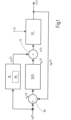
- the Fig. 1 shows a block diagram of the control method according to the invention for a partially electronic system 110, such as an electrohydraulic system 110.
- the partially electronic system 110 has a control system 112 and an electroproportional actuator 114 for influencing a physical control variable y(t) of the system 110 as a function of a control variable u(t).
- a characteristic map 116 is created from correlating state values of the manipulated variable u(t) and controlled variable y(t), the state values of which are used in a second method step during operation of the system 110 for a control process of the system 110 in the form of a targeted setting of a static state of the controlled system 112 of the system 110.
- the characteristic map 116 can be determined each time before commissioning or once before several commissionings of the control system 112 or after maintenance of the control system 112 or after replacement of a component of the control system 112.
- the characteristic map 116 which in this case has value pairs of the manipulated variable u(t) and the controlled variable y(t), is two-dimensional, but can also be three-dimensional if expanded to include another variable.
- the characteristic map 116 is designed in the form of a table or matrix and assigns determined discrete values of the controlled variable y(t) to predetermined discrete values of the manipulated variable u(t).
- Such a characteristic map 116 can also be referred to as a lookup table (LUT) or conversion table.
- the target controlled variable value y s ( t ) is fed exclusively to the controller 18.
- the discrete manipulated variable value u(t) which in the characteristic field 116 corresponds to the target controlled variable value specified for the controller 18 y s ( t ) is fed by the controller 18 to the actuator 114, which accordingly acts on the controlled variable y(t) of the controlled system 112.
- the desired controlled variable value y s ( t ) whose adjustment is desired is fed to the controller 18 and to a first summation point 20 as a reference variable.
- the discrete manipulated variable value u v ( t ) which is assigned in the characteristic map 116 to the desired controlled variable value y s ( t ) specified to the controller 18, is fed by the controller 18 to a second summation point 22.
- the measured actual controlled variable value y m ( t ) is fed to the first summation point 20.
- the first summation point 20 determines the difference between the specified target controlled variable value y s ( t ) and the measured actual controlled variable value y m ( t ), i.e. the controlled variable value deviation e y ( t ), which is fed to a controller 25 of the control system 19, in particular a PID controller 25.
- the controller 25 determines a manipulated variable value deviation e u ( t ) based on the controlled variable value deviation e y ( t ) and feeds this to the second summation point 22.
- the second summation point 22 feeds the sum of its input values, namely the disturbance-corrected manipulated variable value u(t), to the actuator 114, which acts accordingly on the controlled variable y(t) of the controlled system 112.
- control 18 and the regulation 19 superimposed on the control 18 together form a regulation.
- the manipulated variable value u(t) shown with a dashed line continuously runs through a two-phase sequence 30, 52 in a characteristic and sawtooth shape.
- the first phase 30 of the sequence begins at a time 0, from which the manipulated variable value u(t) is increased linearly in a first time period 32 in two sections 36, 38.
- the manipulated variable value u(t) is increased at a first gradient 40 until an initial change in the controlled variable value y(t) shown with a continuous line can be determined.
- the rate of change of the manipulated variable value u(t) should be kept relatively low in order to be able to recognize the incipient change in the controlled variable value y(t) as accurately as possible. If an initial change in the controlled variable value y(t) is determined, a transition is made to the second section 38 of the first time period 32, in which the manipulated variable value u(t) is increased at a second gradient 42 that is greater than the first gradient 40 until a saturation of the controlled variable value y(t) can be determined.
- the saturation of the controlled variable value y(t) can be determined by the fact that its rate of change falls below a predeterminable threshold value, so that no significant increase in the controlled variable value y(t) can be detected any more.
- the second time period 34 of the first phase 30 is initiated.
- the manipulated variable value u(t) is suddenly reduced to a minimum 44, in particular approximately zero, as a result of which the controlled variable y(t) initially drops to a minimum value 50 that is greater than zero.
- the manipulated variable u(t) is already suddenly increased to a minimum value 46 that is greater than zero, at which the controlled variable y(t) maintains its minimum 48.
- the time span between the time at which the manipulated variable value u(t) reaches its minimum 44 and the time at which the manipulated variable value u(t) reaches its minimum 46 is approximately one second.
- the value pair of manipulated variable u(t) and controlled variable value y(t) of the transition from the first section 36 to the second section 38 (time 1) is stored as a start value pair and the saturation of the controlled variable y(t) (time 2) is stored as an end value pair in the characteristic map 116.
- the number of state values of the manipulated variable u(t) lying between these and to be stored in the characteristic map 116 is determined, the correlating controlled variable values y(t) of which are to be determined in the second phase 52.
- the manipulated variable u(t) is initially increased abruptly to the manipulated variable value u(t) of time 1.
- the value of the manipulated variable u(t) is then increased during the first time period 54 of the second phase 52, starting from the manipulated variable value u(t) of time 1 in the direction of the manipulated variable value u(t) of time 2 with a third gradient 58 which is less than the second gradient 42 of the manipulated variable value u(t) in the second section 38 of the first time period 32 of the first phase 30, but slightly greater than the first gradient 40 of the manipulated variable value u(t) in the first section 36 of the first time period 32 of the first phase 30.
- the increase in the manipulated variable u(t) ends with a value which is to be stored as the penultimate manipulated variable value u(t) before the last manipulated variable value u(t) of time 2 in the characteristic map 116, so that the manipulated variable value u(t) of time 2 is not reached in the second phase 52.
- the value of the manipulated variable u(t) is then reduced again to the minimum 44, in particular approximately zero, in the second time period 56 of the second phase 52, whereupon the controlled variable y(t) initially drops to its minimum value 50, which is greater than zero. Even before the value of the controlled variable y(t) reaches its minimum 48, in particular approximately zero, with a time delay, the manipulated variable u(t) is increased abruptly to its minimum value 46, which is greater than zero. This completes the two phases 30, 52 of the automatic recording of the course of the controlled variable characteristic curve for creating the characteristic map 116.
- the associated controlled variable value y(t) is interpolated for a predetermined manipulated variable value u(t) that lies between two manipulated variable values u(t) stored in the characteristic field 116, or the associated manipulated variable value u(t) is interpolated for a predetermined manipulated variable value y(t) that lies between two controlled variable values y(t) stored in the characteristic field 116.
- the interpolated values can be used to control or regulate the controlled variable y(t) in the same way as the values obtained by automatic characteristic curve acquisition.
- the control system 112 can be designed hydromechanically and/or be part of a transport device, a spreading plate, a metering shaft or a mower.
- Fig. 3 shows a first embodiment and Fig. 4 a second embodiment of an electrohydraulic system 110 for carrying out the control method according to the invention.
- the system has a control system 112 with a pressure supply device 60 and a hydraulic consumer 62 in the form of a hydraulic motor 64, and an electroproportional actuator 114 in the form of a 2/2-way proportional valve 66.
- the pressure supply device 60 is connected on the high-pressure side via a first fluid line 68 to the hydraulic motor 64, which is connected on the output side to a tank T via a second fluid line 70.
- the 2/2-way proportional valve 66 is provided in the first fluid line 68, the valve piston of which is electromagnetically controlled with an adjustable closing force, against the force of a compression spring, from a Fig.
- the proportional valve 66 connects its two connections to one another via a fluid path with no flow restriction, whereas this fluid path is blocked in the first end position.
- the control current I of the coil of an actuating device of the proportional valve 66 represents the manipulated variable u(t).
- the respective coil is shown in the figures as a rectangle with an arrow running diagonally relative to it.
- a speed sensor 74 is provided on a motor shaft 72 of the hydraulic motor 64 for the purpose of detecting the controlled variable y(t) in the form of the speed n of the hydraulic motor 64.
- the speed sensor 74 can be designed as a speed-to-frequency converter, speed-to-current converter, speed-to-voltage converter and/or have a CAN bus-based signal output. Alternatively, the speed n of the hydraulic motor 64 can also be detected at another point in the associated mechanics.
- the speed sensor 74 is connected on the input side to a Control 18, 19 is connected as part of the system 110, which is connected on the output side to the actuating device of the proportional valve 66.
- the control 18, 19 carries out the control method according to the invention. By means of this arrangement, the speed n of the hydraulic motor 64 and the volume flow of the fluid delivered by the hydraulic motor 64 can be regulated.
- the first embodiment of the system according to Fig. 3 and the second embodiment of the system according to Fig. 4 differ only in terms of the design and connection of a pressure compensator 76, 78 used.
- a supply pressure compensator 76 is connected in the first fluid line 68 between the pressure supply device 60 and the proportional valve 66, the valve piston of which is between a Fig. 3 shown first end position and a second end position.
- the fluid pressure in the first fluid line 68 between the inlet pressure compensator 76 and the proportional valve 66 acts on the other end of the valve piston.
- the inlet pressure compensator 76 connects the pressure supply device 60 to the proportional valve 66 in a fluid-conducting manner via a flow-free fluid path, whereas this fluid path is blocked in the second end position of the valve piston.
- a circulating pressure compensator 78 is provided, which is connected on the inlet side to the first fluid line 68 between the pressure supply device 60 and Proportional valve 66 and the output side is connected to the second fluid line 70.
- the valve piston of the circulation pressure compensator 78 is between a Fig. 4 shown first end position and a second end position. In the direction of the first end position, a compression spring and the fluid pressure in the first fluid line 68 between the proportional valve 66 and the hydraulic motor 64, which is guided via a third control line 84 to one end of the valve piston of the circulating pressure compensator 78, act on one end of the valve piston of the circulating pressure compensator 78.
- the fluid pressure in the first fluid line 68 between the pressure supply device 60 and the proportional valve 66 which is guided via a fourth control line 86 to the other end of the valve piston of the circulating pressure compensator 78, acts on the other end of the valve piston of the circulating pressure compensator 78.
- the manipulated variable course during characteristic map recording and regularly results from disturbances d(t) acting on the controlled system 112 and/or from inertia effects of the controlled system 112 and/or from a measuring arrangement of the controlled variable y(t), for example by low-pass filtering when measuring the actual controlled variable value y(t).
- Fig. 6 shows a third embodiment and Fig. 7 a fourth embodiment of the electrohydraulic system 110 according to the invention for carrying out the control method.
- the respective system 110 has a control system 112 with a pressure supply device 60 in Form of a hydraulic pump 88 and a hydraulic consumer 62, and an electro-proportional actuator 114 in the form of a proportional valve 66.
- the hydraulic pump 88 is connected on the high-pressure side to the hydraulic consumer 62 via a third fluid line 90.
- the proportional valve 66 is connected on the input side to the third fluid line 90 and on the output side to a tank T via a fourth fluid line 92.
- the control current I of a coil of an actuating device of the proportional valve 66 represents the manipulated variable u(t).
- a pressure sensor 94 is connected on the input side to the fourth fluid line 92 for the purpose of detecting the controlled variable y(t) in the form of a pressure value in the fourth fluid line 92.
- the pressure sensor 94 can be designed as a pressure-to-current converter, pressure-to-voltage converter and/or have a CAN bus-based signal output.
- the pressure sensor 94 is connected to a controller 18 as part of the system 110, which is connected on the output side to the actuating device of the proportional valve 66.
- the controller 18 carries out the control method according to the invention.
- the supply pressure at the consumer 62 can be regulated by means of this arrangement.
- the third embodiment of the system according to Fig. 6 and the fourth embodiment of the system according to Fig. 7 differ only in terms of the design and wiring of the proportional valve 66 used.
- the proportional valve 66 is designed as a pressure relief valve 96.
- the fluid pressure in the fourth fluid line 92 is guided via a sixth control line 100 to an end face of the valve piston of the pressure relief valve 96 and the fluid pressure in the fluid line between the pressure relief valve 96 and tank T is fed via a seventh control line 102 to the actuating device of the pressure relief valve 96.
- the proportional valve 66 is designed as a pressure control valve 98.
- a connection of the pressure control valve 98 is connected via an eighth control line 104 to a swivel angle setting 106 of the hydraulic pump 88 and is led via a ninth control line 108 to an end face of the valve piston of the pressure control valve 98.
- the controlled variable can be the travel of an actuator piston and the manipulated variable can be the control current of a pump motor of a supply pump.
- the coil current I of the actuating device of the respective proportional valve 66 does not correspond to the value zero, but to the minimum value 46.
- the coil current I is reduced to its minimum 44 before it is subsequently raised again to the said minimum value 46.
Landscapes
- Physics & Mathematics (AREA)
- General Physics & Mathematics (AREA)
- Engineering & Computer Science (AREA)
- Automation & Control Theory (AREA)
- Fluid-Pressure Circuits (AREA)
- Feedback Control In General (AREA)
Description
- Die Erfindung betrifft ein Steuerungsverfahren für ein teilelektronisches System, wie ein elektrohydraulisches System, mit den Merkmalen im Oberbegriff von Anspruch 1.
- Die
DE 10 2017 004 299 A1 offenbart eine Vorrichtung zur Geschwindigkeitsregelung und Gleichlaufregelung von hydraulischen Aktuatoren, die insbesondere relativ zueinander bewegbare Teile von Transporteinrichtungen ansteuern, bestehend aus: zumindest einem Aktuator, wie einem hydraulischen Arbeitszylinder; einer Arbeitspumpe in Form einer Konstantpumpe zur Versorgung des Aktuators; einem Schaltventil als Ventilumschalteinrichtung für den Aktuator; einem ein elektroproportionales Stellglied bildenden elektrischen Antrieb für die Arbeitspumpe; einem Wegmesssystem zur Ermittlung der Ist-Position des Aktuators; und einem Frequenzumrichter mit einem Antriebsregler zum Durchführen eines Steuerungsverfahrens, der als Eingangsgrößen Messwerte aus dem Wegmesssystem erhält und mit seinen Ausgangsgrößen die Drehzahl des elektrischen Antriebes und dadurch die Leistung der Arbeitspumpe steuert. - Die
DE 10 2016 214 708 A1 beschreibt ein Steuerungsverfahren und ein Steuerungssystem für ein teilelektronisches System, wie ein elektrohydraulisches System, mit den Schritten im Oberbegriff von Anspruch 1 bzw. 11 mit mindestens einem elektroproportionalen Stellglied, das in Abhängigkeit seiner Stellgröße zur Beeinflussung mindestens einer physikalischen Regelgröße des eine Regelstrecke aufweisenden Systems dient, wobei aus korrelierenden Zustandswerten von Stell- und Regelgröße ein Kennfeld erstellt wird, welches für Steuerungsvorgänge im späteren Betrieb des Systems herangezogen wird. - Weitere Steuerungsverfahren gehen aus der
KR 10-1839039 B1 EP 2 853 752 A1 und derDE 10 2013 206 973 A1 hervor. - Der Erfindung liegt die Aufgabe zugrunde das bekannte Steuerungsverfahren für ein teilelektronisches System dahingehend weiter zu verbessern, dass ein gewünschter Wert einer Regelgröße des Systems mit geringem Aufwand möglichst schnell eingeregelt wird.
- Die dahingehende Aufgabe löst ein Steuerungsverfahren mit den Verfahrensschritten des Patentanspruchs 1 in seiner Gesamtheit.
- Gemäß dem kennzeichnenden Teil des Anspruchs 1 ist das erfindungsgemäße Steuerungsverfahren dadurch gekennzeichnet, dass zur Erstellung des Kennfeldes der Wert der Stellgröße in zwei Phasen sägezahnförmig jeweils zunächst während einer ersten Zeitspanne gesteigert wird bis eine Sättigung des Regelgrößen-Wertes y(t) ermittelt wird und darauffolgend während einer gegenüber der ersten Zeitspanne kürzeren zweiten Zeitspanne reduziert wird.
- Es ist ferner vorgesehen, dass aus korrelierenden Zustandswerten von Stell- und Regelgröße ein Kennfeld erstellt wird, welches für Steuerungsvorgänge im späteren Betrieb des Systems herangezogen wird.
- Dadurch ist bei einem Betrieb des Systems unter Verwendung des Kennfeldes unter Vorgabe des gewünschten Regelgrößen-Wertes das Stellglied mit einem Stellgrößen-Wert ansteuerbar, der ein unverzügliches Einregeln der Regelgröße auf den gewünschten Regelgrößen-Wert bewirkt. Bei einem derart ausgebildeten Steuerungsverfahren entfällt - im Gegensatz zum Stand der Technik - ein zeitaufwändiges Einregeln der Regelgröße im Rahmen einer Einschwingphase aufgrund einer kontinuierlichen Änderung des Stellgrößen-Wertes unter Einbezug eines gemessenen und rückgeführten Regelgrößen-Wertes bis zum Erzielen des gewünschten tatsächlichen Regelgrößen-Wertes. Dazu ist lediglich ein einziges Mal vor Inbetriebnahme der Regelstrecke das Kennfeld zu ermitteln, das mehrfach für Steuerungsvorgänge im Betrieb des Systems herangezogen werden kann. Dies hat so keine Entsprechung im Stand der Technik.
- Gegenstand der Erfindung ist auch ein elektrohydraulisches System zum Durchführen eines Steuerungsverfahrens gemäß Anspruch 11. Das System besteht zumindest aus einer Druckversorgungseinrichtung, einer Regelstrecke mit einem hydraulischen Verbraucher, und aus einem elektroproportionalen Stellglied in Form eines Proportionalventils, das von einer Steuerung ansteuerbar ist, die über eine Sensoreinrichtung aktuelle Zustandswerte einer Regelgröße der Regelstrecke erhält.
- Weitere Vorteile der erfindungsgemäßen Lösungen sind Gegenstand der Unteransprüche.
- Im Folgenden wird ein erfindungsgemäßes Steuerungsverfahren anhand des erfindungsgemäßen elektrohydraulischen Systems mittels der Zeichnung näher erläutert. Dabei zeigen in prinzipieller und nicht maßgeblicher Darstellung die
- Fig. 1
- in der Art eines Blockschaltbildes das erfindungsgemäße Steuerungsverfahren;
- Fig. 2
- in einem kartesischen Koordinatensystem zeitliche Verläufe einer Stellgröße und einer von der Stellgröße abhängigen Regelgröße während der Ermittlung eines Steuer- und Regelgrößen-Wertkombinationen aufweisenden Kennfeldes als Teil des Steuerungsverfahrens;
- Fig. 3
- in der Art eines hydraulischen Schaltplans ein erstes Ausführungsbeispiel eines erfindungsgemäßen Systems zum Durchführen des erfindungsgemäßen Steuerungsverfahrens, bei dem die Regelgröße der Drehzahl eines Hydromotors entspricht;
- Fig. 4
- in der Art eines hydraulischen Schaltplans ein zweites Ausführungsbeispiel des erfindungsgemäßen Systems, bei dem die Regelgröße der Drehzahl eines Hydromotors entspricht;
- Fig. 5
- in einem kartesischen Koordinatensystem Verläufe der tatsächlichen und der gemessenen Regelgröße in Form der Drehzahl des Hydromotors des ersten Ausführungsbeispiels aus
Fig. 3 oder des zweiten Ausführungsbeispiels ausFig. 4 ; - Fig. 6
- in der Art eines hydraulischen Schaltplans ein drittes Ausführungsbeispiel des erfindungsgemäßen Systems, bei dem die Regelgröße dem Versorgungsdruckwert an einem Verbraucher entspricht; und
- Fig. 7
- in der Art eines hydraulischen Schaltplans ein viertes Ausführungsbeispiel des erfindungsgemäßen Systems, bei dem die Regelgröße dem Versorgungsdruckwert an einem Verbraucher entspricht.
- Die
Fig. 1 zeigt ein Blockschaltbild des erfindungsgemäßen Steuerungsverfahrens für ein teilelektronisches System 110, wie beispielsweise ein elektrohydraulisches System 110. Das teilelektronische System 110 weist eine Regelstrecke 112 und ein elektroproportionales Stellglied 114 zum Beeinflussen einer physikalischen Regelgröße y(t) des Systems 110 in Abhängigkeit einer Stellgröße u(t) auf. - In einem ersten Verfahrensschritt wird vor Inbetriebnahme des Systems 110 ein Kennfeld 116 aus korrelierenden Zustandswerten von Stell- u(t) und Regelgröße y(t) erstellt, dessen Zustandswerte in einem zweiten Verfahrensschritt im Betrieb des Systems 110 verwendet werden für einen Steuerungsvorgang des Systems 110 in Form einer gezielten Einstellung eines statischen Zustands der Regelstrecke 112 des Systems 110.
- Das Kennfeld 116 kann ermittelt werden jedes Mal vor Inbetriebnahme oder ein einziges Mal vor mehreren Inbetriebnahmen der Regelstrecke 112 oder nach einer Wartung der Regelstrecke 112 oder nach einem Austausch einer Komponente der Regelstrecke 112.
- Das Kennfeld 116, das vorliegend Wertepaare von Stell- u(t) und Regelgröße y(t) aufweist, ist zweidimensional ausgebildet, kann jedoch um eine weitere Größe erweitert auch dreidimensional ausgebildet sein. Das Kennfeld 116 ist in der Art einer Tabelle oder Matrix ausgebildet und ordnet vorgegebenen diskreten Werten der Stellgröße u(t) ermittelte diskrete Werte der Regelgröße y(t) zu. Ein derartiges Kennfeld 116 kann auch als Lookup Table (LUT) oder Umsetzungstabelle bezeichnet werden.
- Ist lediglich eine das Kennfeld 116 aufweisende Steuerung 18 vorgesehen, wird der Soll-Regelgrößen-Wert ys (t), dessen Einregelung gewünscht ist, ausschließlich der Steuerung 18 zugeführt. Der diskrete Stellgrößen-Wert u(t), der in dem Kennfeld 116 dem der Steuerung 18 vorgebebenen Soll-Regelgrößen-Wert ys (t) zugeordnet ist, wird von der Steuerung 18 dem Stellglied 114 zugeführt, das entsprechend auf die Regelgröße y(t) der Regelstrecke 112 einwirkt.
- Ist der das Kennfeld 116 aufweisenden Steuerung 18 im Sinne einer Vorsteuerung eine Regelung 19 zum Ausregeln von Störgrößen überlagert, wie in
Fig. 1 gezeigt, wird als Führungsgröße der Soll-Regelgrößen-Wert ys (t), dessen Einregelung gewünscht ist, gleichermaßen der Steuerung 18 und einem ersten Summationspunkt 20 zugeführt. Der diskrete Stellgrößen-Wert uv (t), der in dem Kennfeld 116 dem der Steuerung 18 vorgebebenen Soll-Regelgrößen-Wert ys (t) zugeordnet ist, wird von der Steuerung 18 einem zweiten Summationspunkt 22 zugeführt. Dem ersten Summationspunkt 20 wird neben dem vorgegebenen Soll-Regelgrößen-Wert ys (t) der gemessene Ist-Regelgrößen-Wert ym (t) zugeführt. Der erste Summationspunkt 20 ermittelt die Differenz zwischen dem vorgegebenen Soll-Regelgrößen-Wert ys (t) und dem gemessenen Ist-Regelgrößen-Wert ym (t), also die Regelgrö-βen-Wert-Abweichung ey (t), die einem Regler 25 der Regelung 19, insbesondere einem PID-Regler 25, zugeführt wird. Der Regler 25 ermittelt basierend auf der Regelgrößen-Wert-Abweichung ey (t) eine Stellgrößen-Wert-Abweichung eu (t) und führt diese dem zweiten Summationspunkt 22 zu. Der zweite Summationspunkt 22 führt die Summe seiner Eingangswerte, nämlich den störgrößenbereinigten Stellgrößen-Wert u(t) dem Stellglied 114 zu, das entsprechend auf die Regelgröße y(t) der Regelstrecke 112 einwirkt. - Die Steuerung 18 und die der Steuerung 18 überlagerte Regelung 19 bilden gemeinsam eine Regelung.
- Zur automatisierten Erstellung des Kennfeldes 116 durchläuft der mit einer gestrichelten Linie dargestellte Stellgrößen-Wert u(t) kontinuierlich kennlinien- und sägezahnförmig eine zweiphasige Sequenz 30, 52. Die erste Phase 30 der Sequenz beginnt an einem Zeitpunkt 0, ab dem der Stellgrö-βen-Wert u(t) in einer ersten Zeitspanne 32 in zwei Abschnitten 36, 38 jeweils linear gesteigert wird. Während des zeitlich ersten Abschnitts 36 wird der Stellgrößen-Wert u(t) mit einer ersten Steigung 40 so lange gesteigert, bis eine initiale Änderung des mit einer ununterbrochenen Linie dargestellten Regelgrößen-Wertes y(t) ermittelbar ist. In dem ersten Abschnitt 36 sollte die Änderungsrate des Stellgrößen-Wertes u(t) relativ geringgehalten werden, um die einsetzende Änderung des Regelgrößen-Wertes y(t) möglichst genau erkennen zu können. Wird eine initiale Änderung des Regelgrößen-Wertes y(t) ermittelt, wird ein Übergang zum zweiten Abschnitt 38 der ersten Zeitspanne 32 vollzogen, in dem der Stellgrößen-Wert u(t) so lange mit einer gegenüber der ersten Steigung 40 größeren zweiten Steigung 42 gesteigert wird bis eine Sättigung des Regelgrößen-Wertes y(t) ermittelbar ist. Die Sättigung des Regelgrößen-Wertes y(t) ist dadurch ermittelbar, dass deren Änderungsrate einen vorgebbaren Schwellenwert unterschreitet, so dass keine signifikante Zunahme des Regelgrößen-Wertes y(t) mehr zu erkennen ist.
- Wird die Sättigung des Regelgrößen-Wertes y(t) erkannt, wird die zweite Zeitspanne 34 der ersten Phase 30 eingeleitet. In der zweiten Zeitspanne 34 der ersten Phase 30, die gegenüber der ersten Zeitspanne 32 wesentlich kürzer ist, wird der Stellgrößen-Wert u(t) sprungförmig bis auf ein Minimum 44, insbesondere ca. Null, reduziert, wodurch die Regelgröße y(t) zunächst auf einen Mindestwert 50 abfällt, der größer Null ist. Bevor die Regelgröße y(t) mit einer Zeitverzögerung bis auf ein Minimum 48, insbesondere ca. Null, abfällt, wird die Stellgröße u(t) bereits sprungförmig auf einen Mindestwert 46, der größer Null ist, gesteigert, bei dem die Regelgröße y(t) ihr Minimum 48 beibehält. Die Zeitspanne zwischen dem Zeitpunkt, an dem der Stellgrößen-Wert u(t) sein Minimum 44 annimmt, und dem Zeitpunkt, an dem der Stellgrößen-Wert u(t) seinen Mindestwert 46 annimmt, beträgt ca. eine Sekunde.
- Dass die Regelgröße y(t) nach der Reduktion der Stellgröße u(t) nicht sofort, sondern mit einer Zeitverzögerung auf ihr Minimum 48 abfällt, rührt daher, dass die Erfassung der Regelgröße y(t) regelmäßig mittels Impulserfassung erfolgt, die eine Tiefpass-Filterung der Regelgröße y(t) erfordert. Hierdurch kommt es bei abruptem Ausbleiben der Rückführung der Regelgröße y(t) zu einer Fehlinterpretation der Regelgröße y(t) dahingehend, dass der Messwert der Regelgröße y(t) nicht sofort als Null erkannt wird.
- Das Wertepaar aus Stellgrößen- u(t) und Regelgrößen-Wert y(t) des Übergangs von dem ersten Abschnitt 36 zu dem zweiten Abschnitt 38 (Zeitpunkt 1) wird als Startwertepaar und der Sättigung der Regelgröße y(t) (Zeitpunkt 2) wird als Endwertepaar in dem Kennfeld 116 abgelegt. Basierend auf diesem Start und Endwert der Stellgröße u(t) wird die Anzahl der zwischen diesen liegenden, in dem Kennfeld 116 abzulegenden Zustandswerte der Stellgröße u(t) festgelegt, deren korrelierende Regelgrößen-Werte y(t) in der zweiten Phase 52 zu ermitteln sind.
- Zu Beginn der zweiten Phase 52 wird die Stellgröße u(t) zunächst sprungartig auf den Stellgrößen-Wert u(t) des Zeitpunkts 1 gesteigert. Daraufhin wird der Wert der Stellgröße u(t) während der ersten Zeitspanne 54 der zweiten Phase 52 ausgehend von dem Stellgrößen-Wert u(t) des Zeitpunkts 1 in Richtung des Stellgrößen-Wertes u(t) des Zeitpunktes 2 mit einer dritten Steigung 58 gesteigert, die geringer ist als die zweite Steigung 42 des Stellgrößen-Wertes u(t) in dem zweiten Abschnitt 38 der ersten Zeitspanne 32 der ersten Phase 30, jedoch geringfügig größer ist als die erste Steigung 40 des Stellgrößen-Wertes u(t) in dem ersten Abschnitt 36 der ersten Zeitspanne 32 der ersten Phase 30. Dabei endet die Steigerung der Stellgröße u(t) mit einem Wert, der als vorletzter Stellgrößenwert u(t) vor dem letzten Stellgrößen-Wert u(t) des Zeitpunkts 2 in dem Kennfeld 116 abgelegt werden soll, so dass der Stellgrößen-Wert u(t) des Zeitpunktes 2 in der zweiten Phase 52 nicht erreicht wird.
- Während dieser ersten Zeitspanne 54 der zweiten Phase 52 werden mehrere Wertepaare von Stell- u(t) und Regelgröße y(t), vorliegend vierzehn Wertepaare (Zeitpunkte 3 bis 16), in dem Kennfeld 116 abgelegt, deren Stellgrößen-Werte u(t) zwischen dem Startwert der Stellgröße u(t) zum Zeitpunkt 1 und dem Endwert der Stellgröße u(t) zum Zeitpunkt 2 liegen. Die Zustandswerte der Stellgröße u(t) sind vorliegend äquidistant über die erste Zeitspanne 54 der zweiten Phase 52 verteilt, können jedoch aber auch davon abweichend über die erste Zeitspanne 54 der zweiten Phase 52 beliebig verteilt sein.
- Anschließend wird der Wert der Stellgröße u(t) in der zweiten Zeitspanne 56 der zweiten Phase 52 wiederum auf das Minimum 44, insbesondere ca. Null, reduziert, woraufhin die Regelgröße y(t) zunächst auf ihren Mindestwert 50 abfällt, der größer Null ist. Noch bevor der Wert der Regelgröße y(t) mit einer Zeitverzögerung sein Minimum 48, insbesondere ca. Null, erreicht, wird die Stellgröße u(t) sprungförmig auf ihren Mindestwert 46 gesteigert, der größer Null ist. Damit sind die beiden Phasen 30, 52 der automatischen Erfassung des Verlaufs der Regelgrößen-Kennlinie zum Erstellen des Kennfeldes 116 abgeschlossen.
- Denkbar ist, dass unter Verwendung des Kennfeldes 116 zu einem vorgegebenen Stellgrößen-Wert u(t), der zwischen zwei in dem Kennfeld 116 abgelegten Stellgrößen-Werten u(t) liegt, der zugehörige Regelgrößen-Wert y(t) interpoliert wird oder zu einem vorgegebenen Regelgrößen-Wert y(t), der zwischen zwei in dem Kennfeld 116 abgelegten Regelgrößen-Werten y(t) liegt, der zugehörige Stellgrößen-Wert u(t) interpoliert wird. Die interpolierten Werte können genauso wie die durch die automatische Kennlinienerfassung gewonnenen Werte zur Steuerung bzw. Regelung der Regelgröße y(t) dienen.
- Die Regelstrecke 112 kann hydromechanisch ausgebildet sein und/oder Teil einer Transporteinrichtung, eines Streutellers, einer Dosierwelle oder eines Mähwerkes sein.
-
Fig. 3 zeigt ein erstes Ausführungsbeispiel undFig. 4 ein zweites Ausführungsbeispiel eines elektrohydraulischen Systems 110 zum Durchführen des erfindungsgemäßen Steuerungsverfahrens. Das System weist eine Regelstrecke 112 mit einer Druckversorgungseinrichtung 60 und einem hydraulischen Verbraucher 62 in Form eines Hydromotors 64, und ein elektroproportionales Stellglied 114 in Form eines 2/2-Wege-Proportionalventils 66 auf. Die Druckversorgungseinrichtung 60 ist hochdruckseitig über eine erste Fluidleitung 68 mit dem Hydromotor 64 fluidführend verbunden, der ausgangsseitig über eine zweite Fluidleitung 70 an einen Tank T angeschlossen ist. In der ersten Fluidleitung 68 ist das 2/2-Wege-Proportionalventil 66 vorgesehen, dessen Ventilkolben mit einer einstellbaren Schließkraft, elektromagnetisch angesteuert, entgegen der Kraft einer Druckfeder von einer in derFig. 3 und 4 gezeigten ersten Endstellung in eine zweite Endstellung bringbar ist. In der zweiten Endstellung des Ventilkolbens verbindet das Proportionalventil 66 seine beiden Anschlüsse über einen strömungsverengungsfreien Fluidweg miteinander, wohingegen dieser Fluidweg in der ersten Endstellung gesperrt ist. Der Ansteuerstrom I der Spule einer Betätigungseinrichtung des Proportionalventils 66 stellt die Stellgröße u(t) dar. Die jeweilige Spule ist in den Figuren als Rechteck mit einem demgegenüber schräg verlaufenden Pfeil dargestellt. An einer Motorwelle 72 des Hydromotors 64 ist ein Drehzahl-Sensor 74 vorgesehen, zwecks Erfassen der Regelgröße y(t) in Form der Drehzahl n des Hydromotors 64. Der Drehzahl-Sensor 74 kann als Drehzahl-zu-Frequenz-Wandler, Drehzahl-zu-Strom-Wandler, Drehzahl-zu-Spannung-Wandler ausgebildet sein und/oder eine CAN-Bus-basierte Signalausgabe aufweisen. Alternativ kann die Drehzahl n des Hydromotors 64 auch an einer anderen Stelle der zugehörigen Mechanik erfasst werden. Der Drehzahl-Sensor 74 ist eingangsseitig an eine Steuerung 18, 19 als Teil des Systems 110 angeschlossen, die ausgangsseitig an die Betätigungseinrichtung des Proportionalventils 66 angeschlossen ist. Die Steuerung 18,19 führt das erfindungsgemäße Steuerungsverfahren aus. Mittels der dahingehenden Anordnung sind die Drehzahl n des Hydromotors 64 und der Volumenstrom des von dem Hydromotor 64 abgegebenen Fluides regelbar. - Das erste Ausführungsbeispiel des Systems nach
Fig. 3 und das zweite Ausführungsbeispiel des Systems nachFig. 4 unterscheiden sich lediglich hinsichtlich der Ausführung und Verschaltung einer verwendeten Druckwaage 76, 78. - In
Fig. 3 ist in die erste Fluidleitung 68 zwischen der Druckversorgungseinrichtung 60 und dem Proportionalventil 66 eine Zulaufdruckwaage 76 geschaltet, deren Ventilkolben zwischen einer inFig. 3 gezeigten ersten Endstellung und einer zweiten Endstellung verfahrbar ist. In Richtung seiner ersten Endstellung wirken auf die eine Stirnseite des Ventilkolbens der Zulaufdruckwage 76 eine Druckfeder und der Fluiddruck in der ersten Fluidleitung 68 zwischen dem Proportionalventil 66 und dem Hydromotor 64, der über eine erste Steuerleitung 80 auf die eine Stirnseite des Ventilkolbens geführt ist. In Richtung seiner zweiten Endstellung wirkt auf die andere Stirnseite des Ventilkolbens der Fluiddruck in der ersten Fluidleitung 68 zwischen der Zulaufdruckwaage 76 und dem Proportionalventil 66, der über eine zweite Steuerleitung 82 auf die andere Stirnseite des Ventilkolbens der Zulaufdruckwaage 76 geführt ist. In der ersten Endstellung des Ventilkolbens verbindet die Zulaufdruckwaage 76 die Druckversorgungseinrichtung 60 mit dem Proportionalventil 66 fluidführend über einen strömungsverengungsfreien Fluidweg, wohingegen dieser Fluidweg in der zweiten Endstellung des Ventilkolbens gesperrt ist. - In
Fig. 4 ist eine Umlauf-Druckwaage 78 vorgesehen, die eingangsseitig an die erste Fluidleitung 68 zwischen Druckversorgungseinrichtung 60 und Proportionalventil 66 und ausgangsseitig an die zweite Fluidleitung 70 angeschlossen ist. Der Ventilkolben der Umlauf-Druckwaage 78 ist zwischen einer inFig. 4 gezeigten ersten Endstellung und einer zweiten Endstellung verfahrbar. In Richtung der ersten Endstellung wirken auf die eine Stirnseite des Ventilkolbens der Umlauf-Druckwaage 78 eine Druckfeder und der Fluiddruck in der ersten Fluidleitung 68 zwischen dem Proportionalventil 66 und dem Hydromotor 64, der über eine dritte Steuerleitung 84 auf die eine Stirnseite des Ventilkolbens der Umlauf-Druckwaage 78 geführt ist. In Richtung der zweiten Endstellung wirkt auf die andere Stirnseite des Ventilkolbens der Umlauf-Druckwaage 78 der Fluiddruck in der ersten Fluidleitung 68 zwischen der Druckversorgungseinrichtung 60 und dem Proportionalventil 66, der über eine vierte Steuerleitung 86 auf die andere Stirnseite des Ventilkolbens der Umlauf-Druckwaage 78 geführt ist. - In
Fig. 5 ist in Abhängigkeit des von der Betätigungseinrichtung des Proportionalventils 66 aufgenommenen Stromwertes I der Verlauf des tatsächlichen Ist-Regelgrößen-Wertes y(t), der mit einer gestrichelten Linie dargestellt ist, und der Verlauf des mittels des jeweiligen Drehzahlsensors 74 gemessenen Regelgrößen-Wertes ym (t) aufgetragen, der mit einer ununterbrochenen Linie dargestellt ist, die sich in einem Offset unterscheiden. Ein derartiger Offset kann durch eine entsprechende Parametrierung der Sequenz 30, 52, also des Stellgrößenverlaufs, bei der Kennfelderfassung minimiert werden und ergibt sich regelmäßig durch auf die Regelstrecke 112 wirkende Störgrößen d(t) und/oder durch Trägheitseffekte der Regelstrecke 112 und/oder durch eine Messanordnung der Regelgröße y(t), beispielsweise durch die Tiefpass-Filterung bei der Messung des Ist-Regelgrößen-Wertes y(t). -
Fig. 6 zeigt ein drittes Ausführungsbeispiel undFig. 7 ein viertes Ausführungsbeispiel des erfindungsgemäßen elektrohydraulischen Systems 110 zum Durchführen des Steuerungsverfahrens. Das jeweilige System 110 weist eine Regelstrecke 112 mit einer Druckversorgungseinrichtung 60 in Form einer Hydropumpe 88 und einem hydraulischen Verbraucher 62, und ein elektroproportionales Stellglied 114 in Form eines Proportionalventils 66 auf. Die Hydropumpe 88 ist hochdruckseitig über eine dritte Fluidleitung 90 mit dem hydraulischen Verbraucher 62 fluidführend verbunden. Das Proportionalventil 66 ist über eine vierte Fluidleitung 92 eingangsseitig an die dritte Fluidleitung 90 und ausgangsseitig an einen Tank T angeschlossen. Der Ansteuerstrom I einer Spule einer Betätigungseinrichtung des Proportionalventils 66 stellt die Stellgröße u(t) dar. Die jeweilige Spule ist in den Figuren als Rechteck mit einem demgegenüber schräg verlaufenden Pfeil dargestellt. Ein Drucksensor 94 ist eingangsseitig an die vierte Fluidleitung 92 angeschlossen, zwecks Erfassen der Regelgröße y(t) in Form eines Druckwertes in der vierten Fluidleitung 92. Der Drucksensor 94 kann als Druck-zu-Strom-Wandler, Druck-zu-Spannung-Wandlers ausgebildet sein und/oder eine CAN-Bus-basierte Signalausgabe aufweisen. Ausgangsseitig ist der Drucksensor 94 an eine Steuerung 18 als Teil des Systems 110 angeschlossen, die ausgangsseitig an die Betätigungseinrichtung des Proportionalventils 66 angeschlossen ist. Die Steuerung 18 führt das erfindungsgemäße Steuerungsverfahren aus. Mittels der dahingehenden Anordnung ist der Versorgungsdruck am Verbraucher 62 regelbar. - Das dritte Ausführungsbeispiel des Systems nach
Fig. 6 und das vierte Ausführungsbeispiel des Systems nachFig. 7 unterscheiden sich lediglich hinsichtlich der Ausführung und Verschaltung des verwendeten Proportionalventils 66. - In
Fig. 6 ist das Proportionalventil 66 als Druckbegrenzungsventil 96 ausgebildet. Der Fluiddruck in der vierten Fluidleitung 92 ist über eine sechste Steuerleitung 100 auf eine Stirnseite des Ventilkolbens des Druckbegrenzungsventils 96 geführt und der Fluiddruck in der Fluidleitung zwischen Druckbegrenzungsventil 96 und Tank T wird über eine siebte Steuerleitung 102 der Betätigungseinrichtung des Druckbegrenzungsventils 96 zugeführt. - In
Fig. 7 ist das Proportionalventil 66 als Druckregelventil 98 ausgebildet. Ein Anschluss des Druckregelventils 98 ist über eine achte Steuerleitung 104 mit einer Schwenkwinkeleinstellung 106 der Hydropumpe 88 verbunden und über eine neunte Steuerleitung 108 auf eine Stirnseite des Ventilkolbens des Druckregelventils 98 geführt. - Alternativ kann die Regelgröße der Verfahrweg eines Aktuatorkolbens und die Stellgröße der Ansteuerstrom eines Pumpenmotors einer Versorgungspumpe sein.
- Der Spulenstrom I der Betätigungseinrichtung des jeweiligen Proportionalventils 66 entspricht ohne Vorgabe nicht dem Wert Null, sondern dem Mindestwert 46. Während der Erfassung des Kennfeldes 116 wird bei einem abrupten Abfallen des Stellwertes u(t) der Spulenstrom I auf sein Minimum 44 reduziert bevor er anschließend wieder auf den besagten Mindestwert 46 angehoben wird.
Claims (12)
- Steuerungsverfahren für ein teilelektronisches System (110), wie ein elektrohydraulisches System (110), mit mindestens einem elektroproportionalen Stellglied (114), das in Abhängigkeit seiner Stellgröße (u(t)) zur Beeinflussung mindestens einer physikalischen Regelgröße (y(t)) des eine Regelstrecke (112) aufweisenden Systems (110) dient, wobei aus korrelierenden Zustandswerten von Stell- (u(t)) und Regelgröße (y(t)) ein Kennfeld (116) erstellt wird, welches für Steuerungsvorgänge im späteren Betrieb des Systems (110) herangezogen wird, dadurch gekennzeichnet, dass zur Erstellung des Kennfeldes (116) der Wert der Stellgröße (u(t)) in zwei Phasen (30, 52) sägezahnförmig jeweils zunächst während einer ersten Zeitspanne (32, 54) gesteigert wird bis eine Sättigung des Regelgrößen-Wertes y(t) ermittelt wird und darauffolgend während einer gegenüber der ersten Zeitspanne (32, 54) kürzeren zweiten Zeitspanne (34, 56) reduziert wird.
- Steuerungsverfahren nach Anspruch 1, dadurch gekennzeichnet, dass das die Zustandswerte der Stell- (u(t)) und Regelgröße (y(t)) aufweisende Kennfeld (116) zwei- oder dreidimensional ist und dazu dient, mindestens einen statischen Zustand der Regelstrecke (112) des Systems (110) gezielt einzustellen.
- Steuerungsverfahren nach Anspruch 1 oder 2, dadurch gekennzeichnet, dass der das Kennfeld (116) aufweisenden Steuerung (18), die als eine gezielte Vorsteuerung jeweils einen Wert der Regelgröße (y(t)) für die Regelstrecke (112) einstellt, eine Regelung (19) zum Ausregeln von Störgrößen überlagert wird.
- Steuerungsverfahren nach einem der vorstehenden Ansprüche, dadurch gekennzeichnet, dass zur Erstellung des Kennfeldes (116) der Wert der Stellgröße (u(t)) in zwei Phasen (30, 52) sägezahnförmig jeweils zunächst während der ersten Zeitspanne (32, 54) gesteigert wird und darauffolgend während der gegenüber der ersten Zeitspanne (32, 54) kürzeren zweiten Zeitspanne (34, 56) reduziert wird bis auf Null.
- Steuerungsverfahren nach einem der vorstehenden Ansprüche, dadurch gekennzeichnet, dass in der ersten Zeitspanne (32) der ersten Phase (30) der Wert der Stellgröße (u(t)) in zwei Abschnitten (36, 38) jeweils linear gesteigert wird, und dass der Wert der Stellgröße (u(t)) in dem zeitlich ersten Abschnitt (36) so lange mit einer ersten Steigung (40) gesteigert wird bis eine initiale Änderung der Regelgröße (y(t)) ermittelbar ist, woraufhin in dem zeitlich zweiten Abschnitt (38) der Wert der Stellgröße (u(t)) mit einer gegenüber der ersten Steigung (40) größeren zweiten Steigung (42) gesteigert wird bis die Sättigung der Regelgröße (y(t)) ermittelbar ist.
- Steuerungsverfahren nach einem der vorstehenden Ansprüche, dadurch gekennzeichnet, dass das Wertepaar von Stell- (u(t)) und Regelgröße (y(t)) an dem Zeitpunkt des Übergangs von dem ersten Abschnitt (36) zu dem zweiten Abschnitt (38) als Startwertepaar und an dem Zeitpunkt der Sättigung der Regelgröße (y(t)) als Endwertepaar in dem Kennfeld (116) abgelegt werden.
- Steuerungsverfahren nach einem der vorstehenden Ansprüche, dadurch gekennzeichnet, dass in der ersten Zeitspanne (54) der zweiten Phase (52) die Stellgröße (u(t)) mit einer linearen dritten Steigung (58) mit ihrem Startwert beginnend in Richtung ihres Endwertes gesteigert wird.
- Steuerungsverfahren nach einem der vorstehenden Ansprüche, dadurch gekennzeichnet, dass in der ersten Zeitspanne (54) der zweiten Phase (52) zumindest ein Wertepaar von Stell- (u(t)) und Regelgröße (y(t)) in dem Kennfeld (116) abgelegt werden, dessen Stellgrößen-Wert (u(t)) zwischen ihrem Start und ihrem Endwert liegt.
- Steuerungsverfahren nach einem der vorstehenden Ansprüche, dadurch gekennzeichnet, dass die dritte Steigung (58) des Wertes der Stellgröße (u(t)) in der ersten Zeitspanne (54) der zweiten Phase (52) geringer ist als die zweite Steigung (42) des Wertes der Stellgröße (u(t)) in dem zweiten Abschnitt (38) der ersten Zeitspanne (32) der ersten Phase (30).
- Steuerungsverfahren nach einem der vorstehenden Ansprüche, dadurch gekennzeichnet, dass durch eine Parametrierung des Werteverlaufs der Stellgröße (u(t)) eine Abweichung der erfassten Regelgröße (y(t)) von der tatsächlichen Regelgröße (y(t)), insbesondere bedingt durch Trägheitseffekte der Regelstrecke (112) und/oder durch eine Filterung des jeweiligen Regelgrößensignals (y(t)) für dessen Rückführung, begegnet wird.
- Elektrohydraulisches System (110) zum Durchführen eines Steuerungsverfahrens nach einem der vorstehenden Ansprüche, dadurch gekennzeichnet, dass es zumindest besteht aus einer Druckversorgungseinrichtung (60), einer Regelstrecke (112) mit einem hydraulischen Verbraucher (62), und einem elektroproportionalen Stellglied (114) in Form eines Proportionalventils (66), das von einer Steuerung (18) ansteuerbar ist, die über eine Sensoreinrichtung (74, 94) aktuelle Zustandswerte einer Regelgröße (y(t)) der Regelstrecke (112) erhält.
- System nach Anspruch 11, dadurch gekennzeichnet, dass die Sensoreinrichtung (74,94) als Regelgröße (y(t)) die Drehzahl n eines als hydraulischen Verbraucher (62) vorgesehenen Hydromotors (64) der Regelstrecke (112) erfasst oder einen jeweiligen Druckwert eines hydraulischen Kreises der Regelstrecke (112).
Applications Claiming Priority (2)
| Application Number | Priority Date | Filing Date | Title |
|---|---|---|---|
| DE102020002868.3A DE102020002868A1 (de) | 2020-05-13 | 2020-05-13 | Steuerungsverfahren für ein teilelektronisches System |
| PCT/EP2021/059641 WO2021228482A1 (de) | 2020-05-13 | 2021-04-14 | Steuerungsverfahren für ein teilelektronisches system |
Publications (3)
| Publication Number | Publication Date |
|---|---|
| EP4081871A1 EP4081871A1 (de) | 2022-11-02 |
| EP4081871B1 true EP4081871B1 (de) | 2025-01-08 |
| EP4081871C0 EP4081871C0 (de) | 2025-01-08 |
Family
ID=75539338
Family Applications (1)
| Application Number | Title | Priority Date | Filing Date |
|---|---|---|---|
| EP21719115.4A Active EP4081871B1 (de) | 2020-05-13 | 2021-04-14 | Steuerungsverfahren für ein teilelektronisches system |
Country Status (3)
| Country | Link |
|---|---|
| EP (1) | EP4081871B1 (de) |
| DE (1) | DE102020002868A1 (de) |
| WO (1) | WO2021228482A1 (de) |
Families Citing this family (2)
| Publication number | Priority date | Publication date | Assignee | Title |
|---|---|---|---|---|
| DE102022100223B3 (de) * | 2022-01-05 | 2023-05-04 | Samson Aktiengesellschaft | Verfahren und Vorrichtungen zum Regeln einer hoch dynamischen Regelstrecke mit fluidischen Antrieb mithilfe eines Ratenbegrenzers |
| DE102022201584A1 (de) | 2022-02-16 | 2023-08-17 | Robert Bosch Gesellschaft mit beschränkter Haftung | Ventilbaugruppe mit automatisch kalibrierbarer Stellungsregelung |
Family Cites Families (8)
| Publication number | Priority date | Publication date | Assignee | Title |
|---|---|---|---|---|
| DE4410719A1 (de) | 1994-03-28 | 1995-10-05 | Bosch Gmbh Robert | Elektrohydraulisch verstellbare Pumpe |
| DE19961798C2 (de) | 1999-12-22 | 2001-11-15 | Daimler Chrysler Ag | Verfahren und Anordnung zur Regelung des Stroms in einer geschalteten Reluktanzmaschine |
| DE102013206973A1 (de) * | 2013-04-18 | 2014-10-23 | Robert Bosch Gmbh | Steueranordnung |
| DE102013012332A1 (de) * | 2013-07-25 | 2015-01-29 | Hydac Fluidtechnik Gmbh | Regelungssystem |
| DE102015208436B4 (de) | 2015-05-06 | 2019-09-05 | Continental Automotive Gmbh | Überwachungsverfahren und Überwachungsvorrichtung zur Überwachung eines Füllvorgangs einer Injektoranordnung mit einem Kraftstoff und Befüllungsverfahren zum Befüllen einer Injektoranordnung |
| DE102016214708A1 (de) * | 2016-06-30 | 2018-01-04 | Robert Bosch Gmbh | Stetigventileinheit, hydraulische Achse und Verfahren zum Betreiben einer hydraulischen Achse |
| DE102017004299B4 (de) | 2017-05-04 | 2019-05-09 | Hydac International Gmbh | Vorrichtung zur Geschwindigkeitsregelung und Gleichlaufregelung von hydraulischen Aktuatoren |
| KR101839039B1 (ko) * | 2017-05-25 | 2018-04-27 | 엘아이지넥스원 주식회사 | 펌프 기반 유체 정역학적 구동부 제어 시스템 및 그 제어 방법 |
-
2020
- 2020-05-13 DE DE102020002868.3A patent/DE102020002868A1/de active Pending
-
2021
- 2021-04-14 WO PCT/EP2021/059641 patent/WO2021228482A1/de not_active Ceased
- 2021-04-14 EP EP21719115.4A patent/EP4081871B1/de active Active
Also Published As
| Publication number | Publication date |
|---|---|
| EP4081871A1 (de) | 2022-11-02 |
| EP4081871C0 (de) | 2025-01-08 |
| WO2021228482A1 (de) | 2021-11-18 |
| DE102020002868A1 (de) | 2021-11-18 |
Similar Documents
| Publication | Publication Date | Title |
|---|---|---|
| DE3644736C2 (de) | Steueranordnung für mindestens zwei von mindestens einer Pumpe gespeiste hydraulische Verbraucher | |
| DE3207392C2 (de) | Vorrichtung zur selbstanpassenden Stellungsregelung eines Stellgliedes | |
| EP3770431B1 (de) | Hydraulische druckmittelversorgungsanordnung und verfahren | |
| EP1236558B1 (de) | Verfahren zur Regelung der Druckmittelzufuhr zu einem hydraulisch betätigten Aktor | |
| DE102020206343A1 (de) | Verfahren zur Kalibrierung eines elektroproportional verstellbaren Stetigventils | |
| EP0856107A1 (de) | Leistungsregelung mit load-sensing | |
| DE2609434C2 (de) | Einrichtung zur Steuerung eines hydraulischen Motors | |
| DE3787266T2 (de) | Elektrohydraulisches Hilfskraftsystem. | |
| DE10342037A1 (de) | Steueranordnung und Verfahren zur Druckmittelversorgung von zumindest zwei hydraulischen Verbrauchern | |
| EP3748168B1 (de) | Hydraulisches antriebssystem mit zwei pumpen und energierückgewinnung | |
| EP2192309B1 (de) | Verfahren und Regelschaltung zur Regelung einer Druckmittelzufuhr für einen hydraulischen Aktor | |
| EP0164602A2 (de) | Einrichtung zum Regeln des Druckes und der Fördermenge einer verstellbaren Pumpe | |
| EP4081871B1 (de) | Steuerungsverfahren für ein teilelektronisches system | |
| DE102009018071B4 (de) | Verfahren und Regelvorrichtung zur Regelung einer Druckmittelzufuhr für einen hydraulischen Aktor | |
| DE102017213650A1 (de) | Verfahren zum Regeln eines hydraulischen Systems, Regeleinheit für ein hydraulisches System und hydraulisches System | |
| EP0515639B1 (de) | Hydrauliksystem | |
| EP3371466B1 (de) | Verfahren und vorrichtung zum ansteuern einer hydraulisch betätigten antriebseinheit einer armatur | |
| EP4402371B1 (de) | Verfahren für einen hydraulischen antrieb, steuereinheit, computerprogramm, und maschinenlesbares speichermedium | |
| EP0745189B1 (de) | Vorrichtung zur summenleistungsregelung von wenigstens zwei hydrostatischen verstellpumpen | |
| EP4299919A1 (de) | Verfahren zur regelung von hydraulischen komponenten | |
| DE102015221684A1 (de) | Verfahren zum durcksensorlosen Stellen des Drucks eines mittels einer drehzahlgeregelten Pumpe geförderten Fluids | |
| EP3988801A1 (de) | Verfahren zum betreiben eines hydraulischen antriebs | |
| DE102017104792A1 (de) | Systeme und Verfahren zur Kalibrierung elektrohydraulischer Ventile | |
| DE3624328C2 (de) | ||
| DE4307827A1 (de) | Hydrauliksystem |
Legal Events
| Date | Code | Title | Description |
|---|---|---|---|
| STAA | Information on the status of an ep patent application or granted ep patent |
Free format text: STATUS: UNKNOWN |
|
| STAA | Information on the status of an ep patent application or granted ep patent |
Free format text: STATUS: THE INTERNATIONAL PUBLICATION HAS BEEN MADE |
|
| PUAI | Public reference made under article 153(3) epc to a published international application that has entered the european phase |
Free format text: ORIGINAL CODE: 0009012 |
|
| STAA | Information on the status of an ep patent application or granted ep patent |
Free format text: STATUS: REQUEST FOR EXAMINATION WAS MADE |
|
| 17P | Request for examination filed |
Effective date: 20220726 |
|
| AK | Designated contracting states |
Kind code of ref document: A1 Designated state(s): AL AT BE BG CH CY CZ DE DK EE ES FI FR GB GR HR HU IE IS IT LI LT LU LV MC MK MT NL NO PL PT RO RS SE SI SK SM TR |
|
| DAV | Request for validation of the european patent (deleted) | ||
| DAX | Request for extension of the european patent (deleted) | ||
| GRAP | Despatch of communication of intention to grant a patent |
Free format text: ORIGINAL CODE: EPIDOSNIGR1 |
|
| STAA | Information on the status of an ep patent application or granted ep patent |
Free format text: STATUS: GRANT OF PATENT IS INTENDED |
|
| INTG | Intention to grant announced |
Effective date: 20240903 |
|
| GRAS | Grant fee paid |
Free format text: ORIGINAL CODE: EPIDOSNIGR3 |
|
| GRAA | (expected) grant |
Free format text: ORIGINAL CODE: 0009210 |
|
| STAA | Information on the status of an ep patent application or granted ep patent |
Free format text: STATUS: THE PATENT HAS BEEN GRANTED |
|
| AK | Designated contracting states |
Kind code of ref document: B1 Designated state(s): AL AT BE BG CH CY CZ DE DK EE ES FI FR GB GR HR HU IE IS IT LI LT LU LV MC MK MT NL NO PL PT RO RS SE SI SK SM TR |
|
| REG | Reference to a national code |
Ref country code: GB Ref legal event code: FG4D Free format text: NOT ENGLISH |
|
| REG | Reference to a national code |
Ref country code: CH Ref legal event code: EP |
|
| REG | Reference to a national code |
Ref country code: DE Ref legal event code: R096 Ref document number: 502021006368 Country of ref document: DE |
|
| REG | Reference to a national code |
Ref country code: IE Ref legal event code: FG4D Free format text: LANGUAGE OF EP DOCUMENT: GERMAN |
|
| U01 | Request for unitary effect filed |
Effective date: 20250108 |
|
| U07 | Unitary effect registered |
Designated state(s): AT BE BG DE DK EE FI FR IT LT LU LV MT NL PT RO SE SI Effective date: 20250114 |
|
| U20 | Renewal fee for the european patent with unitary effect paid |
Year of fee payment: 5 Effective date: 20250430 |
|
| PG25 | Lapsed in a contracting state [announced via postgrant information from national office to epo] |
Ref country code: RS Free format text: LAPSE BECAUSE OF FAILURE TO SUBMIT A TRANSLATION OF THE DESCRIPTION OR TO PAY THE FEE WITHIN THE PRESCRIBED TIME-LIMIT Effective date: 20250408 |
|
| PG25 | Lapsed in a contracting state [announced via postgrant information from national office to epo] |
Ref country code: PL Free format text: LAPSE BECAUSE OF FAILURE TO SUBMIT A TRANSLATION OF THE DESCRIPTION OR TO PAY THE FEE WITHIN THE PRESCRIBED TIME-LIMIT Effective date: 20250108 |
|
| PG25 | Lapsed in a contracting state [announced via postgrant information from national office to epo] |
Ref country code: ES Free format text: LAPSE BECAUSE OF FAILURE TO SUBMIT A TRANSLATION OF THE DESCRIPTION OR TO PAY THE FEE WITHIN THE PRESCRIBED TIME-LIMIT Effective date: 20250108 |
|
| PG25 | Lapsed in a contracting state [announced via postgrant information from national office to epo] |
Ref country code: IS Free format text: LAPSE BECAUSE OF FAILURE TO SUBMIT A TRANSLATION OF THE DESCRIPTION OR TO PAY THE FEE WITHIN THE PRESCRIBED TIME-LIMIT Effective date: 20250508 Ref country code: NO Free format text: LAPSE BECAUSE OF FAILURE TO SUBMIT A TRANSLATION OF THE DESCRIPTION OR TO PAY THE FEE WITHIN THE PRESCRIBED TIME-LIMIT Effective date: 20250408 |
|
| PG25 | Lapsed in a contracting state [announced via postgrant information from national office to epo] |
Ref country code: HR Free format text: LAPSE BECAUSE OF FAILURE TO SUBMIT A TRANSLATION OF THE DESCRIPTION OR TO PAY THE FEE WITHIN THE PRESCRIBED TIME-LIMIT Effective date: 20250108 |
|
| PG25 | Lapsed in a contracting state [announced via postgrant information from national office to epo] |
Ref country code: GR Free format text: LAPSE BECAUSE OF FAILURE TO SUBMIT A TRANSLATION OF THE DESCRIPTION OR TO PAY THE FEE WITHIN THE PRESCRIBED TIME-LIMIT Effective date: 20250409 |
|
| PG25 | Lapsed in a contracting state [announced via postgrant information from national office to epo] |
Ref country code: SM Free format text: LAPSE BECAUSE OF FAILURE TO SUBMIT A TRANSLATION OF THE DESCRIPTION OR TO PAY THE FEE WITHIN THE PRESCRIBED TIME-LIMIT Effective date: 20250108 |
|
| PG25 | Lapsed in a contracting state [announced via postgrant information from national office to epo] |
Ref country code: CZ Free format text: LAPSE BECAUSE OF FAILURE TO SUBMIT A TRANSLATION OF THE DESCRIPTION OR TO PAY THE FEE WITHIN THE PRESCRIBED TIME-LIMIT Effective date: 20250108 |
|
| PG25 | Lapsed in a contracting state [announced via postgrant information from national office to epo] |
Ref country code: SK Free format text: LAPSE BECAUSE OF FAILURE TO SUBMIT A TRANSLATION OF THE DESCRIPTION OR TO PAY THE FEE WITHIN THE PRESCRIBED TIME-LIMIT Effective date: 20250108 |
|
| PLBE | No opposition filed within time limit |
Free format text: ORIGINAL CODE: 0009261 |
|
| STAA | Information on the status of an ep patent application or granted ep patent |
Free format text: STATUS: NO OPPOSITION FILED WITHIN TIME LIMIT |
|
| REG | Reference to a national code |
Ref country code: CH Ref legal event code: L10 Free format text: ST27 STATUS EVENT CODE: U-0-0-L10-L00 (AS PROVIDED BY THE NATIONAL OFFICE) Effective date: 20251119 |
|
| REG | Reference to a national code |
Ref country code: CH Ref legal event code: H13 Free format text: ST27 STATUS EVENT CODE: U-0-0-H10-H13 (AS PROVIDED BY THE NATIONAL OFFICE) Effective date: 20251125 |
|
| 26N | No opposition filed |
Effective date: 20251009 |
|
| PG25 | Lapsed in a contracting state [announced via postgrant information from national office to epo] |
Ref country code: MC Free format text: LAPSE BECAUSE OF FAILURE TO SUBMIT A TRANSLATION OF THE DESCRIPTION OR TO PAY THE FEE WITHIN THE PRESCRIBED TIME-LIMIT Effective date: 20250108 |
|
| GBPC | Gb: european patent ceased through non-payment of renewal fee |
Effective date: 20250414 |
|
| PG25 | Lapsed in a contracting state [announced via postgrant information from national office to epo] |
Ref country code: GB Free format text: LAPSE BECAUSE OF NON-PAYMENT OF DUE FEES Effective date: 20250414 |
|
| PG25 | Lapsed in a contracting state [announced via postgrant information from national office to epo] |
Ref country code: CH Free format text: LAPSE BECAUSE OF NON-PAYMENT OF DUE FEES Effective date: 20250430 |