EP4080994A1 - Light source apparatus and calibration device - Google Patents
Light source apparatus and calibration device Download PDFInfo
- Publication number
- EP4080994A1 EP4080994A1 EP22159476.5A EP22159476A EP4080994A1 EP 4080994 A1 EP4080994 A1 EP 4080994A1 EP 22159476 A EP22159476 A EP 22159476A EP 4080994 A1 EP4080994 A1 EP 4080994A1
- Authority
- EP
- European Patent Office
- Prior art keywords
- light
- emitting element
- variable
- control function
- unit
- Prior art date
- Legal status (The legal status is an assumption and is not a legal conclusion. Google has not performed a legal analysis and makes no representation as to the accuracy of the status listed.)
- Granted
Links
Images







Classifications
-
- H—ELECTRICITY
- H05—ELECTRIC TECHNIQUES NOT OTHERWISE PROVIDED FOR
- H05B—ELECTRIC HEATING; ELECTRIC LIGHT SOURCES NOT OTHERWISE PROVIDED FOR; CIRCUIT ARRANGEMENTS FOR ELECTRIC LIGHT SOURCES, IN GENERAL
- H05B45/00—Circuit arrangements for operating light-emitting diodes [LED]
- H05B45/10—Controlling the intensity of the light
- H05B45/18—Controlling the intensity of the light using temperature feedback
Definitions
- the present invention relates to a light source apparatus, and more particularly to a light source apparatus that exhibits high controllability for light output.
- the present invention also relates to a calibration device for maintaining high controllability for the light source apparatus.
- a light-emitting element such as a light-emitting diode (LED) varies in an actual amount of light emission depending on the temperature of the light-emitting element even when the same amount of current is applied.
- LED light-emitting diode
- the photosensor itself is affected by temperature, resulting in that it is difficult to control the light output with high accuracy.
- the photosensor is easily affected by other disturbances, so the photosensor has poor followability to a variation in output in a short time.
- feedforward control has been proposed in which a temperature of an LED is measured and a value of a current supplied to the LED is controlled according to a value of the measured temperature (see, for example, Patent Document 1 below).
- Patent Document 1 JP-A-3-36777
- Patent Document 1 a data table in which a relationship among a light output, a temperature, and a current is recorded in advance is prepared, and in order to obtain a desired light output, control is performed to supply a current corresponding to a current value read from the data table to the LED.
- control is performed to supply a current corresponding to a current value read from the data table to the LED.
- an object of the present invention is to provide a light source apparatus capable of performing light output control with high responsiveness even with a smaller amount of data than that of a control method using a conventional feedforward method.
- an object of the present invention is to provide a calibration device for maintaining high controllability for such a light source apparatus.
- a light source apparatus includes:
- the "temperature of the installation location of the light-emitting element” may be a temperature of a region (substrate) in which the light-emitting element is mounted, or may be a temperature of the light-emitting element itself.
- the "temperature of the installation location of the light-emitting element” may be a temperature of the atmosphere in the closed space.
- an amount of current necessary for obtaining a light output corresponding to the target value ⁇ at the current temperature is determined only by performing an arithmetic operation by applying the information regarding the target value ⁇ and the information regarding the temperature of the installation location of the light-emitting element at present to the control function recorded in the first storage unit. Then, the control unit outputs information regarding the determined current amount to the drive circuit, so that a specified amount of current is supplied from the drive circuit to the light-emitting element, and a light output close to the target value ⁇ is obtained.
- the necessary current amount is determined only by performing a simple arithmetic operation by the arithmetic processing unit in the control unit, whereby it is possible to control the light output with a small number of processes. As a result, high responsiveness is achieved.
- the control function is a multidimensional polynomial in which at least one of the independent variables x and y is represented by a multidimensional polynomial of degree two or more.
- the use of the control function described above is particularly effective because highly accurate control can be performed on a light source apparatus used for applications such as an endoscope, an exposure device, and a printing machine.
- the endoscope is used in a situation where the distance between an observation site and a light source changes by the minute. Therefore, when the control function described above is used, the irradiance of the observation site can be constantly maintained with high accuracy.
- the exposure device and the printing machine can repeatedly irradiate an object with a constant dose with high accuracy.
- the control function represented by a linear expression fails to accurately fit the relationship between the current, the temperature, and the light output.
- feedforward control using the control function represented by a linear expression is performed, a non-negligible deviation occurs between the target value ⁇ and the actually obtained light output, and the responsiveness also decreases.
- the information regarding the control function may be derived in advance, for example, before the light source apparatus is shipped, and the derived information may be recorded in the first storage unit.
- the control function is derived as follows. For example, a plurality of relationships between the temperature and the light output is measured with an amount of current being changed to prepare a plurality of coordinates including these three elements, and fitting processing is performed on these coordinates by arithmetic processing.
- the first variable may correspond to the independent variable x
- the second variable corresponds to the independent variable y
- the third variable corresponds to the dependent variable z
- the arithmetic processing unit may determine the supply current amount to the light-emitting element by a value of the dependent variable z in the control function which is obtained by an arithmetic operation based on mathematical formula (1) with applying the temperature T to the independent variable x in the control function and applying the target value ⁇ to the independent variable y in the control function.
- both k and j in mathematical formula (1) may be 2, and the arithmetic processing unit may determine the supply current amount by a current amount I obtained by an arithmetic operation based on mathematical formula (2) below:
- I ⁇ 0 T + ⁇ 1 T ⁇ ⁇ + ⁇ 2 T ⁇ ⁇ 2
- ⁇ 0 ( T ) , ⁇ 1 ( T ) , and ⁇ 2 ( T ) correspond to formulas below, respectively:
- ⁇ 0 T ⁇ 00 + ⁇ 01 ⁇ T + ⁇ 02 ⁇ T 2
- a required current amount I is calculated by simply applying the information corresponding to the temperature T at the installation location of the light-emitting element and the target value ⁇ of the light output to the control function specified by the second degree polynomial with two variables. Therefore, an amount of arithmetic operation is significantly reduced, whereby the responsiveness is extremely improved, and the light output can be controlled in real-time.
- one of the first variable or the second variable may correspond to the independent variable x
- another one may correspond to the dependent variable z
- the third variable may correspond to the independent variable y
- the arithmetic processing unit may transform the control function represented by mathematical formula (1) into a transformation formula for calculating the independent variable y, and determine the supply current amount to the light-emitting element using a value of the independent variable y calculated by an arithmetic operation that applies the temperature T and the target value ⁇ to the corresponding independent variable x and dependent variable z in the transformation formula.
- both k and j in mathematical formula (1) may be 2, and the arithmetic processing unit may determine the supply current amount using a current amount I obtained by an arithmetic operation based on following mathematical formula (3).
- I ⁇ ⁇ 1 T + ⁇ 1 T 2 ⁇ 4 ⁇ ⁇ 2 T ⁇ ⁇ 0 T ⁇ ⁇ 2 ⁇ ⁇ 2 T
- ⁇ 0 ( T ), ⁇ 1 ( T ) , and ⁇ 2 ( T ) correspond to formulas below, respectively:
- ⁇ 0 T ⁇ 00 + ⁇ 01 ⁇ T + ⁇ 02 ⁇ T 2
- the control unit may include an input port receiving an input of information regarding a value of the coefficient ⁇ ts .
- the information regarding the coefficient ⁇ ts corresponding to the light-emitting element is transmitted to the control unit through the input port, whereby the light output control using the control function recorded in the first storage unit can be performed.
- the value of the coefficient ⁇ ts is reviewed with the deterioration of the light-emitting element over time, the value of the coefficient ⁇ ts after the review is also transmitted to the control unit through the input port, whereby light output control using the control function recorded in the first storage unit can be performed.
- the light source apparatus may include a drive unit on which the drive circuit and the control unit are mounted and which is detachable from the light-emitting element, wherein
- a plurality of the light-emitting elements having different wavelengths may be provided, and the first storage unit may record the control function differently for each of the light-emitting elements.
- the light source apparatus includes light-emitting elements of red (R), green (G), and blue (B) to generate white illumination light.
- R red
- G green
- B blue
- a degree of influence on the light output with respect to the temperature changes according to the emission wavelength. Therefore, when an amount of current is equally adjusted for the light-emitting elements of different wavelength bands (color bands), the color balance of the illumination light may change.
- control functions corresponding to the light-emitting elements having different wavelengths are recorded in the control unit, and thus, the light output can be controlled with high accuracy with the color balance being maintained.
- a calibration device performs a calibration process for the above light source apparatus.
- the calibration device includes an information updating unit that creates update information of the coefficient ⁇ ts in the control function and performs update processing on the first storage unit included in the light source apparatus, wherein
- the update control function represented by mathematical formula (4) may be determined using a least-square method.
- the information updating unit may acquire coordinate information including the first actual measurement value, the second actual measurement value, and the measured temperature value for at least (k + 1) ⁇ (j + 1) points, and may determine the update control function by a least-square method based on a plurality of pieces of the coordinate information.
- the relationship between the temperature of the light-emitting element mounted in the light source apparatus and the light output may vary over time.
- the value of the coefficient ⁇ TS corresponding to the light-emitting element at present can be derived by performing the calibration process at a predetermined timing, and by having the information regarding this coefficient ⁇ TS recorded in the first storage unit in the control unit, high controllability over the light output can be maintained.
- the light source apparatus may include a light-receiving sensor that receives light emitted from the light-emitting element, and the information updating unit of the calibration device may acquire the first actual measurement value based on a light amount detected by the light-receiving sensor, may acquire the second actual measurement value based on a controlled amount of a current by the control unit, and may acquire the measured temperature value based on a temperature detected by the temperature detector.
- the calibration device is provided with a function (information updating unit) for performing arithmetic processing based on input information. That is, a general-purpose computer may be used as the calibration device, for example. Furthermore, in a case where the light source apparatus has a communication function, the calibration device can be implemented by a computer located at a position distantfrom the installation location of the light source apparatus or a communication device equipped with an arithmetic processing function.
- the calibration device may include an instruction signal output unit that outputs, to the control unit of the light source apparatus, an instruction signal indicating execution of light emission with an amount of current supplied to the light-emitting element being changed for the calibration process, wherein the information updating unit may acquire the first actual measurement value, the second actual measurement value, and the measured temperature value from the light-emitting element that is in a light emission state in response to the instruction signal.
- a light source apparatus capable of performing light output control with high responsiveness is achieved.
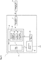
- Fig. 1 is a diagram schematically illustrating an example of a structure of a light source apparatus according to a first embodiment.
- the light source apparatus 1 includes a housing 10, a substrate 11 on which a light-emitting element 12 is mounted, a heat sink 16 for cooling, and a fan 17.
- the substrate 11, the heat sink 16, and the fan 17 are housed in the housing 10.
- the light-emitting element 12 emits light L12 when supplied with an electric current.
- the light source apparatus 1 includes a temperature detector 19 that detects the temperature of an installation location of the light-emitting element 12.
- Fig. 1 illustrates a case where the temperature detector 19 detects the temperature of the substrate 11, but the installation location is not limited as long as the temperature of at least an area correlating with the temperature of the light-emitting element 12 can be detected.
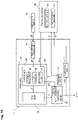
- Fig. 2 is a block diagram schematically illustrating an example of a configuration of the light source apparatus 1.
- a solid arrow indicates a flow of information
- a one-dot chain line arrow indicates a flow of light
- a two-dot chain line arrow indicates a flow of current supplied to the light-emitting element 12. The same applies to the drawings referred to below.
- the light source apparatus 1 includes a drive circuit 21, a control unit 22, and a target light output receiving unit 31.
- the drive circuit 21 is connected to a power supply (not illustrated) and supplies a current to the light-emitting element 12.
- the control unit 22 is a functional unit that controls an amount of current supplied from the drive circuit 21 to the light-emitting element 12.
- the target light output receiving unit 31 is a unit that receives an input of an instruction signal for adjusting the light output of the light source apparatus 1 in response to an instruction from a user.
- a target light output input unit 35 attached to the light source apparatus 1 or provided at a position away from the light source apparatus 1 is operated by the user.
- the target light output input unit 35 includes, for example, an operation button, a knob, a dial, a scroll bar on a touch panel, an input form, etc.
- the user operates the target light output input unit 35 to instruct a desired light output.
- the target light output receiving unit 31 When receiving the input of information regarding the desired light output (information corresponding to a target value ⁇ ) input from the target light output input unit 35, the target light output receiving unit 31 outputs the information to the control unit 22.
- the control unit 22 includes an arithmetic processing unit 25, a first storage unit 26, and an input/output port 27.
- the input/output port 27 is an interface that receives an input of information from the outside of the control unit 22 and outputs information to the outside of the control unit 22.
- the information corresponding to the target value ⁇ may be input to the control unit 22 via the input/output port 27.
- an input port having no output function may be used instead of the input/output port 27.
- the first storage unit 26 includes a storage medium such as a hard disk or a flash memory.
- the arithmetic processing unit 25 applies information regarding a temperature T of the installation location of the light-emitting element 12 input from the temperature detector 19 and information regarding the target value ⁇ of the light output input from the target light output receiving unit 31 to the control function recorded in the first storage unit 26, thereby calculating a supply current amount I (hereinafter sometimes abbreviated as "current amount I") necessary for obtaining the light output of the target value ⁇ under the temperature T by arithmetic processing.
- the arithmetic processing unit 25 is implemented by software or dedicated hardware capable of executing such arithmetic processing.
- Information regarding the current amount I determined by the arithmetic processing unit 25 is output from the control unit 22 to the drive circuit 21.
- the drive circuit 21 supplies an amount of current corresponding to the current amount I to the light-emitting element 12.
- information regarding the current amount I output from the control unit 22 to the driver circuit 21 is represented by the symbol "I”
- the amount of current corresponding to the amount of current I supplied from the drive circuit 21 to the light-emitting element 12 is also represented by the symbol "I”. This is intended to prevent misunderstandings caused by the use of different symbols for the two.
- the same notation is used in Fig. 8 , Fig. 10 to Fig. 12 , which will be described later.
- the temperature detector 19 outputs information regarding the temperature T of the installation location of the light-emitting element 12 to the control unit 22 (arithmetic processing unit 25) at intervals of, for example, several milliseconds to several ten seconds.
- the arithmetic processing unit 25 calculates the supply current amount I by performing arithmetic processing every time the information regarding the temperature T is input.
- the drive circuit 21 adjusts an amount of current supplied to the light-emitting element 12 every time the information regarding the supply current amount I is updated from the control unit 22.
- the light source apparatus 1 is subjected to a process of deriving a control function, for example, before shipment, and the light source apparatus 1 is shipped in a state in which information regarding the control function determined by this process is recorded in the first storage unit 26.
- the light output P of the light L12 and the temperature T detected by the temperature detector 19 are obtained while the amount of current supplied from the drive circuit 21 to the light-emitting element 12 is intentionally changed, and the obtained light output P and temperature T are associated with the current amount I.
- a plurality of coordinates (P, T, I) is obtained.
- a function (control function) in which the obtained coordinate group can be present is derived by fitting processing.
- the information regarding the light output P can be detected on the basis of an amount of light received by a light-receiving sensor installed outside the light source apparatus 1, for example. Furthermore, in a case where a light-receiving sensor 41 (see Fig. 10 ) capable of receiving a part of the light L12 is mounted in the light source apparatus 1 as will be described later, the information regarding the light output P may be detected based on an amount of light received by the light-receiving sensor 41.
- the information regarding the current amount I may be acquired based on information output from the control unit 22 to the drive circuit 21 or may be acquired based on information obtained by actually measuring an amount of current supplied from the drive circuit 21 to the light-emitting element 12 using a current sensor or the like.
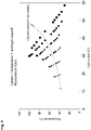
- Fig. 3 is a graph illustrating an example of a result obtained by measuring the light output P of the light L12 and the temperature T detected by the temperature detector 19 with the current amount I being varied.
- the size of a circle corresponds to the magnitude of the current amount I. It is understood that the light output P fluctuates according to the temperature T despite the current amount I being the same, and there is regularity in the fluctuation manner. In addition, it is understood that the light output P fluctuates according to the current amount I despite the temperature T being constant, and there is regularity in the fluctuation manner.
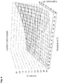
- Fig. 4 is a graph visually indicating a control function obtained by fitting a plurality of coordinate groups obtained in Fig. 3 .
- the control function is defined by an approximate curved surface.
- Formula (1) is described again below.
- at least one of k or j is an integer of 2 or more, and the other is an integer of 1 or more.
- mathematical formula (1) is specifically defined by mathematical formula (5) below.
- z ⁇ 00 + ⁇ 01 ⁇ y + ⁇ 02 ⁇ y 2 + ⁇ 10 ⁇ x + ⁇ 11 ⁇ x ⁇ y + ⁇ 12 ⁇ x ⁇ y 2 + ⁇ 20 ⁇ x 2 + ⁇ 21 ⁇ x 2 ⁇ y + ⁇ 22 ⁇ x 2 ⁇ y 2
- A 1 y 0 y 0 2 x 0 x 0 ⁇ y 0 x 0 ⁇ y 0 2 x 0 2 ⁇ y 0 x 0 2 ⁇ y 0 x 0 2 ⁇ y 0 2 ⁇ ⁇ ⁇ ⁇ ⁇ 1 y n y n 2 x n x n ⁇ y n x n ⁇ y n 2 x n 2 x n 2 ⁇ y n x n 2 ⁇ y n x n 2 ⁇ y n x n 2 ⁇ y n n 2 ⁇ y n n 2 ⁇ y n n 2 ⁇ y n n 2 ⁇ y n n 2
- the coefficient ⁇ ts defined by the vertical vector C in mathematical formula (6) is calculated by an arithmetic operation based on mathematical formula (9) below.
- a T is a transpose of the matrix (vertical vector) A
- (A T ⁇ A) -1 is an inverse matrix of the matrix (A T ⁇ A).
- C A T ⁇ A ⁇ 1 ⁇ A T ⁇ B
- Information regarding the control function calculated in advance using such a method is recorded in the first storage unit 26.
- the arithmetic processing unit 25 of the control unit 22 performs the arithmetic operation by applying the information regarding the target value ⁇ of the light output input from the target light output receiving unit 31 to the variable x of the control function defined by mathematical formula (5), and the temperature T of the installation location of the light-emitting element 12 input from the temperature detector 19 to the variable y of the same function, and determines the supply current amount I based on the obtained value of z.
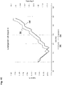
- Fig. 5 is a graph showing a result obtained by comparing a calculated value of the current amount calculated using the control function obtained based on the result of Fig. 4 with an actual current amount.
- the plots on the graph indicate actual measurement values of the current, and the horizontal axis corresponds to a calculated value of the current calculated based on the values of the light output P and the temperature T at a location corresponding to the actual measurement.
- the vertical axis represents a difference between the calculated value and the actual measurement value of the current.
- the actual measurement value and the calculated value substantially correspond to each other, and the value of the difference is also extremely small. That is, it can be seen that the characteristics (relationship among temperature, current, and light output) of the light-emitting element 12 can be expressed by the control function derived based on the actual measurement value.
- Figs. 6A and 6B illustrate control results in a case where the light-receiving sensor receives the light L12 emitted from the light-emitting element 12 and feedback control is performed based on the amount of received light.
- Fig. 6A is a graph illustrating a temporal change in the output of the actually received light L12 (corresponding to (a) in Fig. 6A ) and difference (corresponding to (c) in Fig. 6A ) between the target value of the light output (corresponding to (b) in Fig. 6A ) and the output of the actually received light L12, in a case where the target value of the light output changes from moment to moment.
- Fig. 6B is a graph illustrating a temporal change in the current flowing through the light-emitting element 12 (corresponding to (a) in Fig. 6B ) and the temperature detected by the temperature detector 19 (corresponding to (b) in Fig. 6B ).
- the case where the current control for the light-emitting element 12 was performed by the control unit 22 in the manner described above was taken as an example. That is, in the example, with the control function recorded in the first storage unit 26, the arithmetic processing unit 25 of the control unit 22 calculated the value of z by applying the target value ⁇ of the light output and the temperature T of the installation location of the light-emitting element 12 input from the temperature detector 19 to the control function, respectively, and a current corresponding to the current amount I determined based on the obtained value of z was supplied from the drive circuit 21 to the light-emitting element 12.
- Figs. 7A to 7C show the result of control of the example.
- Fig. 7A is a graph illustrating a temporal change in the output of the actually received light L12 (corresponding to (a) in Fig. 7A ) and difference (corresponding to (c) in Fig. 7A ) between the target value of the light output (corresponding to (b) in Fig. 7A ) and the output of the actually received light L12, in a case where the target value of the light output changes from moment to moment.
- Fig. 7B is a graph illustrating a temporal change in the current flowing through the light-emitting element 12 (corresponding to (a) in Fig. 7B ) and the temperature detected by the temperature detector 19 (corresponding to (b) in Fig. 7B ).
- Fig. 7C is an enlarged graph of a region A in Fig. 7B .
- the light source apparatus 1 of the present embodiment even when an instruction to change the target value ⁇ of the light output is given, an amount of current necessary for achieving the target value ⁇ is determined by arithmetic operation by the control unit 22, and a current in the calculated amount is supplied to the light-emitting element 12. Therefore, it is possible to perform control with high responsiveness.
- the control function is defined by a multidimensional polynomial of degree two or more, it is possible to perform control with high accuracy.
- the light-emitting element 12 may include a second storage unit 42 in which information regarding the coefficient ⁇ ts in the control function corresponding to the light-emitting element 12 is recorded (see Fig. 8 ).
- a second storage unit 42 in which information regarding the coefficient ⁇ ts in the control function corresponding to the light-emitting element 12 is recorded (see Fig. 8 ).
- the coefficient ⁇ ts of a certain light-emitting element 12 hereinafter referred to as a "light-emitting element 12A" for convenience
- the coefficient ⁇ ts of another light-emitting element 12 hereinafter referred to as a "light-emitting element 12B" for convenience
- control unit 22 may read the information regarding the coefficient ⁇ ts recorded in the second storage unit 42 of the light-emitting element 12B and record the read information in the first storage unit 26.
- the light-emitting element 12 may be detachable from the drive unit 20 including the drive circuit 21 and the control unit 22, and the information recorded in the second storage unit 42 of the light-emitting element 12 may be read from the drive unit 20 (control unit 22) by connecting the light-emitting element 12 and the drive unit 20.
- the second storage unit 42 includes, for example, an IC tag, and the drive unit 20 has a function of reading the IC tag.
- the drive unit 20 (control unit 22) reads the IC tag attached to the light-emitting element 12B to be newly attached, and information regarding the coefficient ⁇ ts corresponding to the light-emitting element 12B is recorded in the first storage unit 26.
- the light output decreases even if the same amount of current is supplied to the light-emitting element 12.
- the output control is performed on the light-emitting element 12 using a control function defined based on, for example, the information measured in a test before shipment, the light output may not reach the target light output in a short time.
- a calibration device 50 for correcting the control function corresponding to the light-emitting element 12 may be used as illustrated in Figs. 9 and 10.
- Fig. 10 is a functional block diagram schematically illustrating configurations of the calibration device 50 and the light source apparatus 1.
- the calibration device 50 illustrated in Fig. 10 includes an information updating unit 51 that creates update information of the coefficient ⁇ ts in the control function, and an instruction signal output unit 52 for instructing the start of a calibration process.
- the instruction signal output unit 52 outputs an instruction signal cs instructing the calibration process to the light source apparatus 1.
- the control unit 22 performs control to cause the light-emitting element 12 to emit light while intentionally changing the amount of current supplied from the drive circuit 21 to the light-emitting element 12. Then, information regarding coordinates (P, T, I) in which the light output P (corresponding to a "first actual measurement value") obtained by receiving the light L12 obtained at this time by the light-receiving sensor 41 and the temperature T (corresponding to a "measured temperature value”) detected by the temperature detector 19 are associated with the current amount I (corresponding to a "second actual measurement value”) is output to the information updating unit 51.
- the information updating unit 51 derives a function (control function) in which a given coordinate group can be present by arithmetic processing using fitting processing, and determines a new coefficient ⁇ TS .
- the information regarding the coordinates (P, T, I) is acquired for (k + 1) ⁇ (j + 1) points or more and output to the information updating unit 51.
- the method of the fitting processing may be similar to the method of determining the control function performed before shipment.
- the values of k and j in mathematical formula (4) are the same as the values in mathematical formula (1), and at least one of k or j is an integer of 2 or more and the other is an integer of 1 or more.
- the calibration device 50 has a function of performing a process of deriving a control function corresponding to the light-emitting element 12 at present by performing a test similar to that performed before shipment after the light source apparatus 1 is started to be used. Then, the calibration device 50 outputs the derived update control function to the first storage unit 26 as update information.
- the update information may be only information related to the coefficient ⁇ TS obtained for determining the update control function, or may be information of the function itself.
- the calibration device 50 may be incorporated in the light source apparatus 1.
- a process for reviewing the control function that is, the calibration process
- the accuracy of the light output control is further improved.
- the light source apparatus 1 includes the light-receiving sensor 41, and the information regarding the light output P based on an amount of light received by the light-receiving sensor 41 is transmitted to the calibration device 50.
- the calibration device 50 includes a light-receiving sensor 53 as illustrated in Fig. 12
- the light-receiving sensor 53 in the calibration device 50 may receive a part or all of the light L12 emitted from the light-emitting element 12, and the information updating unit 51 may perform the process of deriving the control function using the light output P based on the received light amount.
- the light source apparatus 1 may include the light-receiving sensor 41 as in Fig. 10 .
- the light source apparatus 1 may include a plurality of light-emitting elements 12 having different wavelengths.
- information regarding different control functions may be recorded in the first storage unit 26 for each of light-emitting elements 12 having different wavelengths.
- the light-emitting element 12 includes a light-emitting element 12R that emits red light, a light-emitting element 12G that emits green light, and a light-emitting element 12B that emits blue light
- a control function used for controlling the light-emitting element 12R, a control function used for controlling the light-emitting element 12G, and a control function used for controlling the light-emitting element 12B are recorded in the first storage unit 26.
- the control unit 22 controlling an amount of current supplied to the light-emitting element 12 based on the control functions set according to the wavelengths as described above, the light output can be controlled with the color balance being maintained.
- the present invention exhibits a high effect in an application requiring maintenance of color balance and controllability of light output, such as a solar simulator.
- the type of light-emitting element 12 is not limited.
- the present invention is applied to the light source apparatus 1 including the light-emitting element 12 having a light output that can be controlled by a supplied amount of current and that is affected by the temperature near the light-emitting element 12.
- the light-emitting element 12 is typically a semiconductor light-emitting element such as an LED or a laser diode (LD).
- the structure of the light source apparatus 1 is not limited.
- the present invention exhibits a high effect particularly when the light source apparatus 1 is used with the output of the light L12 emitted from the light-emitting element 12 being frequently changed. Examples thereof include a light source for an endoscope.
- the present invention also exhibits a high effect in a case where an object is repeatedly irradiated with a constant dose, and examples thereof include an exposure device and a printing machine.
- ⁇ 4> The above embodiments describe the case using a control function that uses the information regarding the light output P and the temperature T as the independent variable (x, y) and the information regarding the current amount I as the dependent variable z.
- the format of the control function recorded in the first storage unit 26 is not limited thereto.
- a control function using information regarding the light output P and the temperature T as the variable (x, z) and information regarding the current amount I as the variable y in mathematical formula (1) may be recorded in the first storage unit 26.
- the arithmetic processing unit 25 transforms the control function represented by mathematical formula (1) into a form of obtaining the value of the variable y and then applies the information regarding the target value ⁇ of the light output and the temperature T to the transformation formula to determine the supply current amount I of the current supplied to the light-emitting element 12, for example.
- I ⁇ ⁇ 1 T + ⁇ 1 T 2 ⁇ 4 ⁇ ⁇ 2 T ⁇ ⁇ 0 T ⁇ ⁇ 2 ⁇ ⁇ 2 T
- ⁇ 4> The above embodiments describe the case of using a least-square method as a method of the processing (fitting processing) of deriving the control function from the coordinates (P, T, I) constituted by the light output P, the temperature T, and the current amount I.
- the fitting processing may be performed by a method other than the least-square method.
- a control function serving as a reference is set by optionally setting the value of the coefficient ⁇ ts (or the coefficient ⁇ TS ), and the deviation between the set control function and the coordinates (P, T, I) is evaluated.
- the control function set by changing the value of the coefficient ⁇ ts (or the coefficient ⁇ TS ) is changed, and the deviation is evaluated similarly.
- This process is repeatedly performed to change the value of the coefficient ⁇ ts (or the coefficient ⁇ TS ) until the deviation becomes sufficiently small, and the control function represented by mathematical formula (1) or (4) may be specified by the determined value of the coefficient ⁇ ts (or the coefficient ⁇ TS ).
Landscapes
- Semiconductor Lasers (AREA)
- Circuit Arrangement For Electric Light Sources In General (AREA)
- Arrangement Of Elements, Cooling, Sealing, Or The Like Of Lighting Devices (AREA)
- Led Devices (AREA)
Abstract
Description
- The present invention relates to a light source apparatus, and more particularly to a light source apparatus that exhibits high controllability for light output. The present invention also relates to a calibration device for maintaining high controllability for the light source apparatus.
- It is known that a light-emitting element such as a light-emitting diode (LED) varies in an actual amount of light emission depending on the temperature of the light-emitting element even when the same amount of current is applied. Under such a background, as a technique for stabilizing the light output of the LED, there is conventionally feedback control in which a part of the emitted light from the LED is received by a photosensor, and an amount of current supplied from a power supply circuit to the LED is adjusted based on the amount of received light.
- However, in the feedback control using a photosensor, the photosensor itself is affected by temperature, resulting in that it is difficult to control the light output with high accuracy. In addition, the photosensor is easily affected by other disturbances, so the photosensor has poor followability to a variation in output in a short time.
- As a countermeasure to such a problem, feedforward control has been proposed in which a temperature of an LED is measured and a value of a current supplied to the LED is controlled according to a value of the measured temperature (see, for example,
Patent Document 1 below). - Patent Document 1:
JP-A-3-36777 - Accordingto the method described in
Patent Document 1, a data table in which a relationship among a light output, a temperature, and a current is recorded in advance is prepared, and in order to obtain a desired light output, control is performed to supply a current corresponding to a current value read from the data table to the LED. However, in order to accurately control the light output by this method, it is necessary to record a huge amount of data in the data table. - In addition, it is necessary to perform processing of reading data close to the desired light output and to the measured temperature from the data table and complement processing in order to determine a necessary current amount, and therefore, there is a limit in achieving quick responsiveness. In particular, for a light source used in an application, such as an endoscope, in which a light output is expected to be finely adjusted during illumination, quick responsiveness to the adjustment of the light output is required, and thus, it is difficult to adopt the above-described control method.
- Given the above problems, an object of the present invention is to provide a light source apparatus capable of performing light output control with high responsiveness even with a smaller amount of data than that of a control method using a conventional feedforward method. In addition, an object of the present invention is to provide a calibration device for maintaining high controllability for such a light source apparatus.
- A light source apparatus according to the present invention includes:
- a light-emitting element;
- a temperature detector that detects a temperature of an installation location of the light-emitting element;
- a drive circuit that supplies a current to the light-emitting element;
- a control unit that controls the current supplied from the drive circuit to the light-emitting element; and
- a target light output receiving unit that receives an input of information corresponding to a target value Φ of a light output of the light-emitting element, wherein
- the control unit includes:
- a first storage unit in which a control function is recorded for obtaining a third variable correlated with the current supplied to the light-emitting element from a first variable correlated with the temperature of the installation location of the light-emitting element and a second variable correlated with the light output of the light-emitting element; and
- an arithmetic processing unit that determines a supply current amount to the light-emitting element, which is the third variable, by reading the control function from the first storage unit, substituting a temperature T detected by the temperature detector for the first variable, and substituting the target value Φ for which the target light output receiving unit has received input for the second variable,
- the control function is a curved surface function specified in mathematical formula (1) below that includes an independent variable x, an independent variable y, and a dependent variable z, the control function being a function converted into a formula for obtaining the third variable by assigning the first variable, the second variable, and the third variable to one of the independent variable x, the independent variable y, and the dependent variable z, and
- the curved surface function has a shape determined by a coefficient αts in mathematical formula (1) below

- where αts (0 ≤ t ≤ k, 0 ≤ s ≤ j) is the coefficient, one of k or j is an integer of 2 or more, and another one is an integer of 1 or more.
- The "temperature of the installation location of the light-emitting element" may be a temperature of a region (substrate) in which the light-emitting element is mounted, or may be a temperature of the light-emitting element itself. When the light-emitting element is placed in a closed space, the "temperature of the installation location of the light-emitting element" may be a temperature of the atmosphere in the closed space.
- According to the above configuration, when the information corresponding to a desired light output (target value Φ) is input, an amount of current necessary for obtaining a light output corresponding to the target value Φ at the current temperature is determined only by performing an arithmetic operation by applying the information regarding the target value Φ and the information regarding the temperature of the installation location of the light-emitting element at present to the control function recorded in the first storage unit. Then, the control unit outputs information regarding the determined current amount to the drive circuit, so that a specified amount of current is supplied from the drive circuit to the light-emitting element, and a light output close to the target value Φ is obtained.
- That is, according to the above configuration, the necessary current amount is determined only by performing a simple arithmetic operation by the arithmetic processing unit in the control unit, whereby it is possible to control the light output with a small number of processes. As a result, high responsiveness is achieved.
- In addition, since one of k or j in mathematical formula (1) is an integer of two or more as described above, the control function is a multidimensional polynomial in which at least one of the independent variables x and y is represented by a multidimensional polynomial of degree two or more. The use of the control function described above is particularly effective because highly accurate control can be performed on a light source apparatus used for applications such as an endoscope, an exposure device, and a printing machine. The endoscope is used in a situation where the distance between an observation site and a light source changes by the minute. Therefore, when the control function described above is used, the irradiance of the observation site can be constantly maintained with high accuracy. Further, when using the control function described above, the exposure device and the printing machine can repeatedly irradiate an object with a constant dose with high accuracy. Note that the control function represented by a linear expression fails to accurately fit the relationship between the current, the temperature, and the light output. As a result, when feedforward control using the control function represented by a linear expression is performed, a non-negligible deviation occurs between the target value Φ and the actually obtained light output, and the responsiveness also decreases.
- The information regarding the control function may be derived in advance, for example, before the light source apparatus is shipped, and the derived information may be recorded in the first storage unit. The control function is derived as follows. For example, a plurality of relationships between the temperature and the light output is measured with an amount of current being changed to prepare a plurality of coordinates including these three elements, and fitting processing is performed on these coordinates by arithmetic processing.
- The first variable may correspond to the independent variable x, the second variable corresponds to the independent variable y, the third variable corresponds to the dependent variable z, and
the arithmetic processing unit may determine the supply current amount to the light-emitting element by a value of the dependent variable z in the control function which is obtained by an arithmetic operation based on mathematical formula (1) with applying the temperature T to the independent variable x in the control function and applying the target value Φ to the independent variable y in the control function. - In this case, both k and j in mathematical formula (1) may be 2, and the arithmetic processing unit may determine the supply current amount by a current amount I obtained by an arithmetic operation based on mathematical formula (2) below:


- According to the above configuration, a required current amount I is calculated by simply applying the information corresponding to the temperature T at the installation location of the light-emitting element and the target value Φ of the light output to the control function specified by the second degree polynomial with two variables. Therefore, an amount of arithmetic operation is significantly reduced, whereby the responsiveness is extremely improved, and the light output can be controlled in real-time.
- Besides the configuration described above, one of the first variable or the second variable may correspond to the independent variable x, another one may correspond to the dependent variable z, the third variable may correspond to the independent variable y, and the arithmetic processing unit may transform the control function represented by mathematical formula (1) into a transformation formula for calculating the independent variable y, and determine the supply current amount to the light-emitting element using a value of the independent variable y calculated by an arithmetic operation that applies the temperature T and the target value Φ to the corresponding independent variable x and dependent variable z in the transformation formula.
- In this case, both k and j in mathematical formula (1) may be 2, and the arithmetic processing unit may determine the supply current amount using a current amount I obtained by an arithmetic operation based on following mathematical formula (3).


- The control unit may include an input port receiving an input of information regarding a value of the coefficient αts.
- According to the configuration described above, even in a case where, for example, the light-emitting element is replaced, the information regarding the coefficient αts corresponding to the light-emitting element is transmitted to the control unit through the input port, whereby the light output control using the control function recorded in the first storage unit can be performed. In addition, even in a case where the value of the coefficient αts is reviewed with the deterioration of the light-emitting element over time, the value of the coefficient αts after the review is also transmitted to the control unit through the input port, whereby light output control using the control function recorded in the first storage unit can be performed.
- In the above configuration, the light source apparatus may include a drive unit on which the drive circuit and the control unit are mounted and which is detachable from the light-emitting element, wherein
- the light-emitting element may include a second storage unit in which information regarding the value of the coefficient αts uniquely assigned to the light-emitting element is recorded, and
- when the drive unit and the light-emitting element are connected, information regarding the value of the coefficient αts recorded in the second storage unit may be input to the control unit via the input port.
- According to the above configuration, information regarding the value of the coefficient αts is recorded in the light-emitting element. Therefore, even when, for example, the light-emitting element is replaced, the value of the coefficient αts recorded in the first storage unit of the control unit is automatically updated, whereby light output control for the replaced light-emitting element can be accurately performed.
- A plurality of the light-emitting elements having different wavelengths may be provided, and
the first storage unit may record the control function differently for each of the light-emitting elements. - It is conceivable that the light source apparatus includes light-emitting elements of red (R), green (G), and blue (B) to generate white illumination light. In the light-emitting element, a degree of influence on the light output with respect to the temperature changes according to the emission wavelength. Therefore, when an amount of current is equally adjusted for the light-emitting elements of different wavelength bands (color bands), the color balance of the illumination light may change. On the other hand, according to the above configuration, control functions corresponding to the light-emitting elements having different wavelengths are recorded in the control unit, and thus, the light output can be controlled with high accuracy with the color balance being maintained.
- A calibration device according to the present invention performs a calibration process for the above light source apparatus. The calibration device includes an information updating unit that creates update information of the coefficient αts in the control function and performs update processing on the first storage unit included in the light source apparatus, wherein
- the information updating unit
- determines, by arithmetic processing, an update control function represented by mathematical formula (4) in which a first actual measurement value correlated with a light output from the light-emitting element, a second actual measurement value correlated with an amount of current supplied to the light-emitting element, and a measured temperature value correlated with a temperature of the installation location of the light-emitting element are associated with any of an independent variable X, an independent variable Y, and a dependent variable Z under a light-emitting state of the light-emitting element, and
- outputs information regarding a coefficient αTS in the update control function to the first storage unit as the update information:

- where values of k and j in mathematical formula (4) coincide with the values of k and j in mathematical formula (1), respectively.
- In the calibration device, the update control function represented by mathematical formula (4) may be determined using a least-square method. In detail, the information updating unit may acquire coordinate information including the first actual measurement value, the second actual measurement value, and the measured temperature value for at least (k + 1) × (j + 1) points, and may determine the update control function by a least-square method based on a plurality of pieces of the coordinate information.
- As the light source apparatus has been used, the relationship between the temperature of the light-emitting element mounted in the light source apparatus and the light output may vary over time. According to the above calibration device, the value of the coefficient αTS corresponding to the light-emitting element at present can be derived by performing the calibration process at a predetermined timing, and by having the information regarding this coefficient αTS recorded in the first storage unit in the control unit, high controllability over the light output can be maintained.
- The light source apparatus may include a light-receiving sensor that receives light emitted from the light-emitting element, and
the information updating unit of the calibration device may acquire the first actual measurement value based on a light amount detected by the light-receiving sensor, may acquire the second actual measurement value based on a controlled amount of a current by the control unit, and may acquire the measured temperature value based on a temperature detected by the temperature detector. - According to the above configuration, it is only sufficient that the calibration device is provided with a function (information updating unit) for performing arithmetic processing based on input information. That is, a general-purpose computer may be used as the calibration device, for example. Furthermore, in a case where the light source apparatus has a communication function, the calibration device can be implemented by a computer located at a position distantfrom the installation location of the light source apparatus or a communication device equipped with an arithmetic processing function.
- The calibration device may include an instruction signal output unit that outputs, to the control unit of the light source apparatus, an instruction signal indicating execution of light emission with an amount of current supplied to the light-emitting element being changed for the calibration process,
wherein the information updating unit may acquire the first actual measurement value, the second actual measurement value, and the measured temperature value from the light-emitting element that is in a light emission state in response to the instruction signal. - According to the present invention, a light source apparatus capable of performing light output control with high responsiveness is achieved.
-
-
Fig. 1 is a diagram schematically illustrating an example of a structure of a light source apparatus according to a first embodiment; -
Fig. 2 is a functional block diagram schematically illustrating an example of a configuration of the light source apparatus; -
Fig. 3 is a graph illustrating an example of a result obtained by measuring a light output P and a temperature T with a current amount I being varied; -
Fig. 4 is a graph visually indicating a control function obtained by fitting a plurality of coordinate groups obtained inFig. 3 ; -
Fig. 5 is a graph showing a result obtained by comparing a calculated value of a current amount calculated using a control function obtained based on the result ofFig. 4 with an actually measured current amount; -
Fig. 6A is a graph showing a result in a case where control is performed by a method (feedback) according to a comparative example and shows a temporal change in a target value of a light output, an actual measurement value of an actual light output, and difference between the target value and the actual measurement value; -
Fig. 6B is a graph showing a result in a case where control is performed by the method (feedback) according to the comparative example and shows a temporal change in an amount of current supplied to the light-emitting element and a temperature of an installation location of the light-emitting element; -
Fig. 7A is a graph showing a result in a case where control is performed by a method (feedforward using a control function) according to an example and shows a temporal change in a target value of a light output, an actual measurement value of an actual light output, and difference between the target value and the actual measurement value; -
Fig. 7B is a graph showing a result in a case where control is performed by the method (feedforward using a control function) according to the example and shows a temporal change in an amount of current supplied to the light-emitting element and a temperature of an installation location of the light-emitting element; -
Fig. 7C is an enlarged graph of a partial region inFig. 7B ; -
Fig. 8 is a functional block diagram schematically illustrating an example of another configuration of the light source apparatus; -
Fig. 9 is a diagram schematically illustrating configurations of a calibration device and the light source apparatus; -
Fig. 10 is a functional block diagram schematically illustrating configuration examples of the calibration device and the light source apparatus; -
Fig. 11 is a functional block diagram schematically illustrating another configuration examples of the calibration device and the light source apparatus; and -
Fig. 12 is a functional block diagram schematically illustrating another configuration examples of the calibration device and the light source apparatus. - Embodiments of a light source apparatus and a calibration device according to the present invention will be described with reference to the drawings as appropriate.
-
Fig. 1 is a diagram schematically illustrating an example of a structure of a light source apparatus according to a first embodiment. Thelight source apparatus 1 includes ahousing 10, asubstrate 11 on which a light-emittingelement 12 is mounted, aheat sink 16 for cooling, and afan 17. Thesubstrate 11, theheat sink 16, and thefan 17 are housed in thehousing 10. The light-emittingelement 12 emits light L12 when supplied with an electric current. - The
light source apparatus 1 includes atemperature detector 19 that detects the temperature of an installation location of the light-emittingelement 12.Fig. 1 illustrates a case where thetemperature detector 19 detects the temperature of thesubstrate 11, but the installation location is not limited as long as the temperature of at least an area correlating with the temperature of the light-emittingelement 12 can be detected. -
Fig. 2 is a block diagram schematically illustrating an example of a configuration of thelight source apparatus 1. InFig. 2 , a solid arrow indicates a flow of information, a one-dot chain line arrow indicates a flow of light, and a two-dot chain line arrow indicates a flow of current supplied to the light-emittingelement 12. The same applies to the drawings referred to below. - The
light source apparatus 1 includes adrive circuit 21, acontrol unit 22, and a target lightoutput receiving unit 31. Thedrive circuit 21 is connected to a power supply (not illustrated) and supplies a current to the light-emittingelement 12. Thecontrol unit 22 is a functional unit that controls an amount of current supplied from thedrive circuit 21 to the light-emittingelement 12. - The target light
output receiving unit 31 is a unit that receives an input of an instruction signal for adjusting the light output of thelight source apparatus 1 in response to an instruction from a user. As an example, a target lightoutput input unit 35 attached to thelight source apparatus 1 or provided at a position away from thelight source apparatus 1 is operated by the user. The target lightoutput input unit 35 includes, for example, an operation button, a knob, a dial, a scroll bar on a touch panel, an input form, etc. When intending to increase or decrease the light output of the light L12 at present, the user operates the target lightoutput input unit 35 to instruct a desired light output. When receiving the input of information regarding the desired light output (information corresponding to a target value Φ) input from the target lightoutput input unit 35, the target lightoutput receiving unit 31 outputs the information to thecontrol unit 22. - The
control unit 22 includes anarithmetic processing unit 25, afirst storage unit 26, and an input/output port 27. The input/output port 27 is an interface that receives an input of information from the outside of thecontrol unit 22 and outputs information to the outside of thecontrol unit 22. For example, the information corresponding to the target value Φ may be input to thecontrol unit 22 via the input/output port 27. In the present embodiment, an input port having no output function may be used instead of the input/output port 27. - In the
first storage unit 26, information regarding a control function to be described later is recorded. Thefirst storage unit 26 includes a storage medium such as a hard disk or a flash memory. Thearithmetic processing unit 25 applies information regarding a temperature T of the installation location of the light-emittingelement 12 input from thetemperature detector 19 and information regarding the target value Φ of the light output input from the target lightoutput receiving unit 31 to the control function recorded in thefirst storage unit 26, thereby calculating a supply current amount I (hereinafter sometimes abbreviated as "current amount I") necessary for obtaining the light output of the target value Φ under the temperature T by arithmetic processing. Thearithmetic processing unit 25 is implemented by software or dedicated hardware capable of executing such arithmetic processing. - Information regarding the current amount I determined by the
arithmetic processing unit 25 is output from thecontrol unit 22 to thedrive circuit 21. Thedrive circuit 21 supplies an amount of current corresponding to the current amount I to the light-emittingelement 12. InFig. 2 , information regarding the current amount I output from thecontrol unit 22 to thedriver circuit 21 is represented by the symbol "I", while the amount of current corresponding to the amount of current I supplied from thedrive circuit 21 to the light-emittingelement 12 is also represented by the symbol "I". This is intended to prevent misunderstandings caused by the use of different symbols for the two. The same notation is used inFig. 8 ,Fig. 10 to Fig. 12 , which will be described later. - The
temperature detector 19 outputs information regarding the temperature T of the installation location of the light-emittingelement 12 to the control unit 22 (arithmetic processing unit 25) at intervals of, for example, several milliseconds to several ten seconds. Thearithmetic processing unit 25 calculates the supply current amount I by performing arithmetic processing every time the information regarding the temperature T is input. Thedrive circuit 21 adjusts an amount of current supplied to the light-emittingelement 12 every time the information regarding the supply current amount I is updated from thecontrol unit 22. - Next, the control function recorded in the
first storage unit 26 will be described. - The
light source apparatus 1 is subjected to a process of deriving a control function, for example, before shipment, and thelight source apparatus 1 is shipped in a state in which information regarding the control function determined by this process is recorded in thefirst storage unit 26. - Specifically, the light output P of the light L12 and the temperature T detected by the
temperature detector 19 are obtained while the amount of current supplied from thedrive circuit 21 to the light-emittingelement 12 is intentionally changed, and the obtained light output P and temperature T are associated with the current amount I. Thus, a plurality of coordinates (P, T, I) is obtained. Then, a function (control function) in which the obtained coordinate group can be present is derived by fitting processing. - Here, the information regarding the light output P can be detected on the basis of an amount of light received by a light-receiving sensor installed outside the
light source apparatus 1, for example. Furthermore, in a case where a light-receiving sensor 41 (seeFig. 10 ) capable of receiving a part of the light L12 is mounted in thelight source apparatus 1 as will be described later, the information regarding the light output P may be detected based on an amount of light received by the light-receivingsensor 41. In addition, the information regarding the current amount I may be acquired based on information output from thecontrol unit 22 to thedrive circuit 21 or may be acquired based on information obtained by actually measuring an amount of current supplied from thedrive circuit 21 to the light-emittingelement 12 using a current sensor or the like. -
Fig. 3 is a graph illustrating an example of a result obtained by measuring the light output P of the light L12 and the temperature T detected by thetemperature detector 19 with the current amount I being varied. InFig. 3 , the size of a circle corresponds to the magnitude of the current amount I. It is understood that the light output P fluctuates according to the temperature T despite the current amount I being the same, and there is regularity in the fluctuation manner. In addition, it is understood that the light output P fluctuates according to the current amount I despite the temperature T being constant, and there is regularity in the fluctuation manner. -
Fig. 4 is a graph visually indicating a control function obtained by fitting a plurality of coordinate groups obtained inFig. 3 . In the example ofFig. 4 , the control function is defined by an approximate curved surface. - More specifically, the control function defined in mathematical formula (1) mentioned above is fitted to the measurement result (xi, yi, zi) (where i = 0, 1,..., n) obtained by assigning the light output P to the variable x, the temperature T to the variable y, and the current amount I to the variable z using, for example, the least-square method. Formula (1) is described again below. In mathematical formula (1), at least one of k or j is an integer of 2 or more, and the other is an integer of 1 or more.

- A case where k = 2 and j = 2 will now be described in detail as a specific example. In this case, mathematical formula (1) is specifically defined by mathematical formula (5) below.

- When expressed as a vertical vector C, a coefficient αts to be obtained can be defined by mathematical formula (6) below.

- When expressed as a vertical vector B, the measurement result zi (where i = 0, 1, ..., n) regarding the current amount I can be defined by mathematical formula (7) below.

- A matrix A expressed by mathematical formula (8) below is defined using the measurement resultxi regarding the light output P and the measurement result yi (where i = 0, 1, ..., n) regarding the temperature T.

- In this case, the coefficient αts defined by the vertical vector C in mathematical formula (6) is calculated by an arithmetic operation based on mathematical formula (9) below. In mathematical formula (9), AT is a transpose of the matrix (vertical vector) A, and (AT · A)-1 is an inverse matrix of the matrix (AT · A).

- Each element of the matrix C obtained by mathematical formula (9) corresponds to the coefficient αts (t = 0, 1, 2; s = 0, 1, 2). That is, a formula obtained by applying each coefficient αts to mathematical formula (5) corresponds to the control function. This control function is a function obtained by fitting the measurement result (xi, yi, zi) (where i = 0, 1, ..., n) using a least-square method, and corresponds to a curved surface function in the present embodiment. That is, each coefficient αts is a factor for determining the shape of the curved surface function.
- Information regarding the control function calculated in advance using such a method is recorded in the
first storage unit 26. Taking the control function defined by mathematical formula (5) as an example, the information regarding the control function is recorded in thefirst storage unit 26 with the values of the coefficients αts (t = 0, 1, 2; s = 0, 1, 2) being already recorded. Thearithmetic processing unit 25 of thecontrol unit 22 performs the arithmetic operation by applying the information regarding the target value Φ of the light output input from the target lightoutput receiving unit 31 to the variable x of the control function defined by mathematical formula (5), and the temperature T of the installation location of the light-emittingelement 12 input from thetemperature detector 19 to the variable y of the same function, and determines the supply current amount I based on the obtained value of z. -
Fig. 5 is a graph showing a result obtained by comparing a calculated value of the current amount calculated using the control function obtained based on the result ofFig. 4 with an actual current amount. The plots on the graph indicate actual measurement values of the current, and the horizontal axis corresponds to a calculated value of the current calculated based on the values of the light output P and the temperature T at a location corresponding to the actual measurement. In addition, the vertical axis represents a difference between the calculated value and the actual measurement value of the current. - According to the result of
Fig. 5 , it is understood that the actual measurement value and the calculated value substantially correspond to each other, and the value of the difference is also extremely small. That is, it can be seen that the characteristics (relationship among temperature, current, and light output) of the light-emittingelement 12 can be expressed by the control function derived based on the actual measurement value. - As a comparative example,
Figs. 6A and6B illustrate control results in a case where the light-receiving sensor receives the light L12 emitted from the light-emittingelement 12 and feedback control is performed based on the amount of received light.Fig. 6A is a graph illustrating a temporal change in the output of the actually received light L12 (corresponding to (a) inFig. 6A ) and difference (corresponding to (c) inFig. 6A ) between the target value of the light output (corresponding to (b) inFig. 6A ) and the output of the actually received light L12, in a case where the target value of the light output changes from moment to moment. In addition,Fig. 6B is a graph illustrating a temporal change in the current flowing through the light-emitting element 12 (corresponding to (a) inFig. 6B ) and the temperature detected by the temperature detector 19 (corresponding to (b) inFig. 6B ). - On the other hand, the case where the current control for the light-emitting
element 12 was performed by thecontrol unit 22 in the manner described above was taken as an example. That is, in the example, with the control function recorded in thefirst storage unit 26, thearithmetic processing unit 25 of thecontrol unit 22 calculated the value of z by applying the target value Φ of the light output and the temperature T of the installation location of the light-emittingelement 12 input from thetemperature detector 19 to the control function, respectively, and a current corresponding to the current amount I determined based on the obtained value of z was supplied from thedrive circuit 21 to the light-emittingelement 12. -
Figs. 7A to 7C show the result of control of the example.Fig. 7A is a graph illustrating a temporal change in the output of the actually received light L12 (corresponding to (a) inFig. 7A ) and difference (corresponding to (c) inFig. 7A ) between the target value of the light output (corresponding to (b) inFig. 7A ) and the output of the actually received light L12, in a case where the target value of the light output changes from moment to moment. In addition,Fig. 7B is a graph illustrating a temporal change in the current flowing through the light-emitting element 12 (corresponding to (a) inFig. 7B ) and the temperature detected by the temperature detector 19 (corresponding to (b) inFig. 7B ).Fig. 7C is an enlarged graph of a region A inFig. 7B . - Comparing
Fig. 6A withFig. 7A , it can be seen that, in the comparative example, about three to seven seconds is spent until the actual light output reaches the target value after the instruction regarding the target value of the light output is given. Therefore, regarding the light output, a certain degree of difference occurs between the target value and the actual measurement value. On the other hand, in the example, a time taken until the actual light output reaches the target value after the instruction regarding the target value of the light output is given is extremely short. This is indicated inFig. 7A in which the curve of (a) and the curve of (b) substantially overlap each other and the value of the difference is nearly zero at all times. - This can also be understood by comparing
Fig. 6B andFig. 7B . It is understood that the current flowing through the light-emittingelement 12 in the comparative example has a larger variation amount during control than the current flowing through the light-emittingelement 12 in the example. This indicates that, in the control method used in the comparative example, the light output is separated from the target value, so that the control for constantly changing the current amount is performed. It is to be noted that, in the example, the current amount also varies a little according to the temperature change, and this is indicated inFig. 7C that is an enlarged graph of a portion of the graph inFig. 7B . - As described above, according to the
light source apparatus 1 of the present embodiment, even when an instruction to change the target value Φ of the light output is given, an amount of current necessary for achieving the target value Φ is determined by arithmetic operation by thecontrol unit 22, and a current in the calculated amount is supplied to the light-emittingelement 12. Therefore, it is possible to perform control with high responsiveness. In addition, since the control function is defined by a multidimensional polynomial of degree two or more, it is possible to perform control with high accuracy. - The light-emitting
element 12 may include asecond storage unit 42 in which information regarding the coefficient αts in the control function corresponding to the light-emittingelement 12 is recorded (seeFig. 8 ). For example, there is a case where the light-emittingelement 12 is to be replaced in thelight source apparatus 1. In this case, the coefficient αts of a certain light-emitting element 12 (hereinafter referred to as a "light-emitting element 12A" for convenience) and the coefficient αts of another light-emitting element 12 (hereinafter referred to as a "light-emitting element 12B" for convenience) are not necessarily the same. Therefore, when the light-emitting element 12A is replaced with the light-emitting element 12B and the light-emitting element 12B is attached to thelight source apparatus 1, thecontrol unit 22 may read the information regarding the coefficient αts recorded in thesecond storage unit 42 of the light-emitting element 12B and record the read information in thefirst storage unit 26. - As a more specific example, the light-emitting
element 12 may be detachable from thedrive unit 20 including thedrive circuit 21 and thecontrol unit 22, and the information recorded in thesecond storage unit 42 of the light-emittingelement 12 may be read from the drive unit 20 (control unit 22) by connecting the light-emittingelement 12 and thedrive unit 20. Furthermore, as another example, thesecond storage unit 42 includes, for example, an IC tag, and thedrive unit 20 has a function of reading the IC tag. When the light-emitting element 12A is replaced with the light-emitting element 12B, the drive unit 20 (control unit 22) reads the IC tag attached to the light-emitting element 12B to be newly attached, and information regarding the coefficient αts corresponding to the light-emitting element 12B is recorded in thefirst storage unit 26. - When the
light source apparatus 1 is continuously used for a long period of time, the light output decreases even if the same amount of current is supplied to the light-emittingelement 12. In this case, even when the output control is performed on the light-emittingelement 12 using a control function defined based on, for example, the information measured in a test before shipment, the light output may not reach the target light output in a short time. - In view of this, a
calibration device 50 for correcting the control function corresponding to the light-emittingelement 12 may be used as illustrated inFigs. 9 and10. Fig. 10 is a functional block diagram schematically illustrating configurations of thecalibration device 50 and thelight source apparatus 1. - The
calibration device 50 illustrated inFig. 10 includes aninformation updating unit 51 that creates update information of the coefficient αts in the control function, and an instructionsignal output unit 52 for instructing the start of a calibration process. - When the calibration process is performed, the instruction
signal output unit 52 outputs an instruction signal cs instructing the calibration process to thelight source apparatus 1. When confirming the input of the calibration instruction signal cs, thecontrol unit 22 performs control to cause the light-emittingelement 12 to emit light while intentionally changing the amount of current supplied from thedrive circuit 21 to the light-emittingelement 12. Then, information regarding coordinates (P, T, I) in which the light output P (corresponding to a "first actual measurement value") obtained by receiving the light L12 obtained at this time by the light-receivingsensor 41 and the temperature T (corresponding to a "measured temperature value") detected by thetemperature detector 19 are associated with the current amount I (corresponding to a "second actual measurement value") is output to theinformation updating unit 51. Theinformation updating unit 51 derives a function (control function) in which a given coordinate group can be present by arithmetic processing using fitting processing, and determines a new coefficient αTS. The information regarding the coordinates (P, T, I) is acquired for (k + 1) × (j + 1) points or more and output to theinformation updating unit 51. The k and j herein are the same as k and j in mathematical formula (1). That is, in a case where k = 2 and j = 2 as in the above example, the information regarding the coordinates (P, T, I) for nine or more points is acquired. - The method of the fitting processing may be similar to the method of determining the control function performed before shipment. Specifically, the control function defined in mathematical formula (4) similar to mathematical formula (1) is fitted to the measurement result (Xi, Yi, Zi) (where i = 0, 1,..., n) obtained by assigning the light output P to the variable X, the temperature T to the variable Y, and the current amount I to the variable Z using, for example, the least-square method, whereby an update control function is determined. Note that the values of k and j in mathematical formula (4) are the same as the values in mathematical formula (1), and at least one of k or j is an integer of 2 or more and the other is an integer of 1 or more.

- As described above, the information regarding the control function derived by performing a light emission test on the light-emitting
element 12 before shipment is recorded in thefirst storage unit 26 included in thecontrol unit 22. Thecalibration device 50 according to the present embodiment has a function of performing a process of deriving a control function corresponding to the light-emittingelement 12 at present by performing a test similar to that performed before shipment after thelight source apparatus 1 is started to be used. Then, thecalibration device 50 outputs the derived update control function to thefirst storage unit 26 as update information. Note that, at this time, the update information may be only information related to the coefficient αTS obtained for determining the update control function, or may be information of the function itself. - As illustrated in
Fig. 11 , thecalibration device 50 may be incorporated in thelight source apparatus 1. In this case, a process for reviewing the control function (that is, the calibration process) can be frequently performed, and thus, the accuracy of the light output control is further improved. - Furthermore, in the example illustrated in
Fig. 10 , thelight source apparatus 1 includes the light-receivingsensor 41, and the information regarding the light output P based on an amount of light received by the light-receivingsensor 41 is transmitted to thecalibration device 50. However, in a case where thecalibration device 50 includes a light-receivingsensor 53 as illustrated inFig. 12 , the light-receivingsensor 53 in thecalibration device 50 may receive a part or all of the light L12 emitted from the light-emittingelement 12, and theinformation updating unit 51 may perform the process of deriving the control function using the light output P based on the received light amount. Note that, in the configuration illustrated inFig. 12 , thelight source apparatus 1 may include the light-receivingsensor 41 as inFig. 10 . - Another embodiment will be described below.
- <1> The
light source apparatus 1 may include a plurality of light-emittingelements 12 having different wavelengths. In this case, information regarding different control functions may be recorded in thefirst storage unit 26 for each of light-emittingelements 12 having different wavelengths. For example, in a case where the light-emittingelement 12 includes a light-emitting element 12R that emits red light, a light-emitting element 12G that emits green light, and a light-emitting element 12B that emits blue light, a control function used for controlling the light-emitting element 12R, a control function used for controlling the light-emitting element 12G, and a control function used for controlling the light-emitting element 12B are recorded in thefirst storage unit 26. - Due to the
control unit 22 controlling an amount of current supplied to the light-emittingelement 12 based on the control functions set according to the wavelengths as described above, the light output can be controlled with the color balance being maintained. For example, the present invention exhibits a high effect in an application requiring maintenance of color balance and controllability of light output, such as a solar simulator. - <2> In the present invention, the type of light-emitting
element 12 is not limited. The present invention is applied to thelight source apparatus 1 including the light-emittingelement 12 having a light output that can be controlled by a supplied amount of current and that is affected by the temperature near the light-emittingelement 12. It is to be noted, however, that the light-emittingelement 12 is typically a semiconductor light-emitting element such as an LED or a laser diode (LD). - <3> In the present invention, the structure of the
light source apparatus 1 is not limited. However, the present invention exhibits a high effect particularly when thelight source apparatus 1 is used with the output of the light L12 emitted from the light-emittingelement 12 being frequently changed. Examples thereof include a light source for an endoscope. The present invention also exhibits a high effect in a case where an object is repeatedly irradiated with a constant dose, and examples thereof include an exposure device and a printing machine. - <4> The above embodiments describe the case using a control function that uses the information regarding the light output P and the temperature T as the independent variable (x, y) and the information regarding the current amount I as the dependent variable z. However, the format of the control function recorded in the
first storage unit 26 is not limited thereto. For example, a control function using information regarding the light output P and the temperature T as the variable (x, z) and information regarding the current amount I as the variable y in mathematical formula (1) may be recorded in thefirst storage unit 26. In this case, thearithmetic processing unit 25 transforms the control function represented by mathematical formula (1) into a form of obtaining the value of the variable y and then applies the information regarding the target value Φ of the light output and the temperature T to the transformation formula to determine the supply current amount I of the current supplied to the light-emittingelement 12, for example. - As a specific example, when the supply current amount I to be obtained corresponds to the variable y, the light output P corresponds to the variable x, and the temperature T corresponds to the variable z in mathematical formula (5) above, the supply current amount I is obtained using the transformation formula indicated by mathematical formula (3) above. Formula (3) is described again below.


- <4> The above embodiments describe the case of using a least-square method as a method of the processing (fitting processing) of deriving the control function from the coordinates (P, T, I) constituted by the light output P, the temperature T, and the current amount I. However, the fitting processing may be performed by a method other than the least-square method. As an example, a control function serving as a reference is set by optionally setting the value of the coefficient αts (or the coefficient αTS), and the deviation between the set control function and the coordinates (P, T, I) is evaluated. Next, the control function set by changing the value of the coefficient αts (or the coefficient αTS) is changed, and the deviation is evaluated similarly. This process is repeatedly performed to change the value of the coefficient αts (or the coefficient αTS) until the deviation becomes sufficiently small, and the control function represented by mathematical formula (1) or (4) may be specified by the determined value of the coefficient αts (or the coefficient αTS).
Claims (12)
- A light source apparatus (1) comprising:a light-emitting element (12);a temperature detector (19) that detects a temperature of an installation location of the light-emitting element (12);a drive circuit (21) that supplies a current to the light-emitting element (12);a control unit (22) that controls the current supplied from the drive circuit (21) to the light-emitting element (12); anda target light output receiving unit (31) that receives an input of information corresponding to a target value Φ of a light output of the light-emitting element (12),whereinthe control unit (22) includes:a first storage unit (26) in which a control function is recorded for obtaining a third variable correlated with the current supplied to the light-emitting element (12) from a first variable correlated with the temperature of the installation location of the light-emitting element (12) and a second variable correlated with the light output of the light-emitting element (12); andan arithmetic processing unit (25) that determines a supply current amount to the light-emitting element (12), which is the third variable, by reading the control function from the first storage unit (26), substituting a temperature T detected by the temperature detector (19) for the first variable, and substituting the target value Φ for which the target light output receiving unit has received input for the second variable,the control function is a curved surface function specified in mathematical formula (1) below that includes an independent variable x, an independent variable y, and a dependent variable z, the control function being a function converted into a formula for obtaining the third variable by assigning the first variable, the second variable, and the third variable to one of the independent variable x, the independent variable y, and the dependent variable z, andthe curved surface function has a shape determined by a coefficient αts in mathematical formula (1) below:
 where αts (0 ≤ t ≤ k, 0 ≤ s ≤ j) is the coefficient, one of k or j is an integer of 2 or more, and another one is an integer of 1 or more.
 - The light source apparatus (1) according to claim 1, whereinthe first variable corresponds to the independent variable x, the second variable corresponds to the independent variable y, the third variable corresponds to the dependent variable z, andthe arithmetic processing unit (25) determines the supply current amount to the light-emitting element (12) by a value of the dependent variable z in the control function which is obtained by an arithmetic operation based on mathematical formula (1) with applying the temperature T to the independent variable x in the control function and applying the target value Φ to the independent variable y in the control function.
- The light source apparatus (1) according to claim 1, whereinone of the first variable and the second variable corresponds to the independent variable x, the other to the dependent variable z, the third variable corresponds to the independent variable y, andthe arithmetic processing unit (25) transforms the control function represented by mathematical formula (1) into a transformed formula for calculating the independent variable y and determines the supply current amount to the light-emitting element (12) by a value of the independent variable y calculated by an arithmetic operation that applies the temperature T and the target value Φ to the corresponding independent variable x and dependent variable z, respectively, in the transformed formula.
- The light source apparatus (1) according to claim 2, whereinin mathematical formula (1), both k and j are 2, andthe arithmetic processing unit (25) determines the supply current amount by a current amount I obtained by an arithmetic operation based on mathematical formula (2) below:



- The light source apparatus (1) according to claim 3, whereinin mathematical formula (1), both k and j are 2, andthe arithmetic processing unit (25) determines the supply current amount by a current amount I obtained by an arithmetic operation based on mathematical formula (3) below:



- The light source apparatus (1) according to any one of claims 1 to 5, wherein the control unit (22) includes an input port (27) receiving an input of information regarding a value of the coefficient αts.
- The light source apparatus (1) according to claim 6, further comprisinga drive unit (20) on which the drive circuit and the control unit are mounted and which is detachable from the light-emitting element (12),whereinthe light-emitting element (12) includes a second storage unit (42) in which information regarding the value of the coefficient αts uniquely assigned to the light-emitting element (12) is recorded, andwhen the drive unit (20) and the light-emitting element (12) are connected, information regarding the value of the coefficient αts recorded in the second storage unit (42) is input to the control unit (22) via the input port (27).
- The light source apparatus (1) according to any one of claims 1 to 7, whereina plurality of the light-emitting elements (3, 3,...) having different wavelengths is provided, andthe first storage unit (26) records the control function different for each of the light-emitting elements (3, 3,...).
- A calibration device (50) that performs a calibration process for the light source apparatus (1) according to any one of claims 1 to 8, the calibration device (50) comprisingan information updating unit (51) that creates update information of the coefficient αts in the control function and performs update processing on the first storage unit (26) included in the light source apparatus (1),whereinthe information updating unit (51)determines, by arithmetic processing, an update control function represented by mathematical formula (4) in which a first actual measurement value correlated with a light output from the light-emitting element (12), a second actual measurement value correlated with an amount of current supplied to the light-emitting element (12), and a measured temperature value correlated with a temperature of the installation location of the light-emitting element (12) are associated with any of an independent variable X, an independent variable Y, and a dependent variable Z under a light-emitting state of the light-emitting element (12), andoutputs information regarding a coefficient αTS in the update control function to the first storage unit (26) as the update information:
 where values of k and j in mathematical formula (4) coincide with the values of k and j in mathematical formula (1), respectively.
 - The calibration device (50) according to claim 9, wherein the information updating unit (51) acquires coordinate information including the first actual measurement value, the second actual measurement value, and the measured temperature value for at least (k + 1) × (j + 1) points, and determines the update control function by a least-square method based on a plurality of pieces of the coordinate information.
- The calibration device (50) according to claim 9 or 10, whereinthe light source apparatus (1) includes a light-receiving sensor (41) that receives light emitted from the light-emitting element (12), andthe information updating unit (51) acquires the first actual measurement value based on a light amount detected by the light-receiving sensor (41), acquires the second actual measurement value based on a controlled amount of a current by the control unit (22), and acquires the measured temperature value based on a temperature detected by the temperature detector (19).
- The calibration device (50) according to any one of claims 9 to 11, further comprisingan instruction signal output unit (52) that outputs, to the control unit (22) of the light source apparatus (1), an instruction signal indicating execution of light emission with an amount of current supplied to the light-emitting element (12) being changed for the calibration process,wherein the information updating unit (51) acquires the first actual measurement value, the second actual measurement value, and the measured temperature value from the light-emitting element (12) that is in a light emission state in response to the instruction signal.
Applications Claiming Priority (1)
| Application Number | Priority Date | Filing Date | Title |
|---|---|---|---|
| JP2021032812A JP7545115B2 (en) | 2021-03-02 | 2021-03-02 | Light source device and calibration device |
Publications (2)
| Publication Number | Publication Date |
|---|---|
| EP4080994A1 true EP4080994A1 (en) | 2022-10-26 |
| EP4080994B1 EP4080994B1 (en) | 2024-06-12 |
Family
ID=80623478
Family Applications (1)
| Application Number | Title | Priority Date | Filing Date |
|---|---|---|---|
| EP22159476.5A Active EP4080994B1 (en) | 2021-03-02 | 2022-03-01 | Light source apparatus and calibration device |
Country Status (3)
| Country | Link |
|---|---|
| EP (1) | EP4080994B1 (en) |
| JP (1) | JP7545115B2 (en) |
| TW (1) | TWI878646B (en) |
Citations (3)
| Publication number | Priority date | Publication date | Assignee | Title |
|---|---|---|---|---|
| JPH0336777A (en) | 1989-07-04 | 1991-02-18 | Fujitsu Ltd | Controller for light emitting element driving circuit |
| US20070040512A1 (en) * | 2005-08-17 | 2007-02-22 | Tir Systems Ltd. | Digitally controlled luminaire system |
| DE102007044556A1 (en) * | 2007-09-07 | 2009-03-12 | Arnold & Richter Cine Technik Gmbh & Co. Betriebs Kg | Method and device for adjusting the color or photometric properties of an LED lighting device |
Family Cites Families (10)
| Publication number | Priority date | Publication date | Assignee | Title |
|---|---|---|---|---|
| JP2004140509A (en) * | 2002-10-16 | 2004-05-13 | Hitachi Cable Ltd | Optical transmitter |
| KR100813382B1 (en) * | 2003-07-28 | 2008-03-12 | 니치아 카가쿠 고교 가부시키가이샤 | Light- emitting apparatus, led illumination, led light-emitting apparatus, and method of controlling light-emitting apparatus |
| JP2006049674A (en) * | 2004-08-06 | 2006-02-16 | Nippon Telegr & Teleph Corp <Ntt> | Light source for optical communication and control method thereof |
| JP2006080235A (en) * | 2004-09-08 | 2006-03-23 | Nippon Telegr & Teleph Corp <Ntt> | Light source for optical communication |
| JP4064986B2 (en) * | 2005-08-17 | 2008-03-19 | 日本電信電話株式会社 | Method for selecting measurement points for optical output wavelength characteristics, optical output power characteristics, and RF amplitude characteristics |
| JP4081095B2 (en) * | 2005-03-16 | 2008-04-23 | 日本電信電話株式会社 | Method of selecting measurement points for optical output wavelength characteristics and optical output power characteristics stored in light source for optical communication |
| US9985414B1 (en) * | 2017-06-16 | 2018-05-29 | Banner Engineering Corp. | Open-loop laser power-regulation |
| WO2019216150A1 (en) * | 2018-05-09 | 2019-11-14 | 三菱電機株式会社 | System for adjusting and inspecting light transmission module, method for adjusting and inspecting light transmission module, and method for manufacturing light transmission module |
| JP7092999B2 (en) * | 2018-05-15 | 2022-06-29 | ミツミ電機株式会社 | Control device, optical scanning device, display device and control method |
| WO2020008566A1 (en) * | 2018-07-04 | 2020-01-09 | 三菱電機株式会社 | Laser diode drive device and optical transmitter |
-
2021
- 2021-03-02 JP JP2021032812A patent/JP7545115B2/en active Active
-
2022
- 2022-02-09 TW TW111104690A patent/TWI878646B/en active
- 2022-03-01 EP EP22159476.5A patent/EP4080994B1/en active Active
Patent Citations (3)
| Publication number | Priority date | Publication date | Assignee | Title |
|---|---|---|---|---|
| JPH0336777A (en) | 1989-07-04 | 1991-02-18 | Fujitsu Ltd | Controller for light emitting element driving circuit |
| US20070040512A1 (en) * | 2005-08-17 | 2007-02-22 | Tir Systems Ltd. | Digitally controlled luminaire system |
| DE102007044556A1 (en) * | 2007-09-07 | 2009-03-12 | Arnold & Richter Cine Technik Gmbh & Co. Betriebs Kg | Method and device for adjusting the color or photometric properties of an LED lighting device |
Also Published As
| Publication number | Publication date |
|---|---|
| EP4080994B1 (en) | 2024-06-12 |
| JP7545115B2 (en) | 2024-09-04 |
| TWI878646B (en) | 2025-04-01 |
| TW202306793A (en) | 2023-02-16 |
| JP2022133879A (en) | 2022-09-14 |
Similar Documents
| Publication | Publication Date | Title |
|---|---|---|
| US11666987B2 (en) | Laser power control device, laser machining device, and laser power control method | |
| US20250060657A1 (en) | Method and system for color point calibration of light source projector | |
| EP4212963A1 (en) | Control device, method for adjusting control device, lithography device, and article manufacturing method | |
| CN105142922A (en) | Method and device for laser marking with grey level calibration | |
| EP4080994B1 (en) | Light source apparatus and calibration device | |
| US7092413B2 (en) | Laser machining apparatus | |
| US9980336B2 (en) | Light receiving device, light emitting device and light receiving/emitting device | |
| US7015447B2 (en) | Illuminance calibrating method of illuminator, illuminance calibration controller of illuminator, illuminance calibrating program of illuminator, recording medium storing the program and measuring tool | |
| JP5632698B2 (en) | Color processing apparatus and method | |
| JP2007310008A (en) | Display device using LED | |
| US6441579B1 (en) | Current magnitude variation correction for open loop stepper motor driver circuit | |
| JP2013019870A (en) | Mirror cooling dew-point meter | |
| WO2021140969A1 (en) | Laser output control method, and laser processing device | |
| EP4568423A1 (en) | Optical output control system | |
| US20220086958A1 (en) | Power control device and power control method | |
| EP4168754B1 (en) | Mass flow meters, controllers and methods having improved accuracy | |
| JP5612448B2 (en) | Light emitting element driving method | |
| JP2013008857A (en) | Fiber laser oscillator and fiber laser processing device | |
| JP2010103293A (en) | Optical transmitter | |
| KR100597766B1 (en) | Exposure equipment | |
| JP2025065720A (en) | Optical Output Control System | |
| JP5034405B2 (en) | Optical communication device | |
| CN117008658A (en) | Temperature control method, computer-readable storage medium and electronic device | |
| JP2014123051A (en) | Luminance control method and liquid crystal display device | |
| US20220050207A1 (en) | Light projecting device, tof sensor provided with same and distance image generator |
Legal Events
| Date | Code | Title | Description |
|---|---|---|---|
| PUAI | Public reference made under article 153(3) epc to a published international application that has entered the european phase |
Free format text: ORIGINAL CODE: 0009012 |
|
| STAA | Information on the status of an ep patent application or granted ep patent |
Free format text: STATUS: THE APPLICATION HAS BEEN PUBLISHED |
|
| AK | Designated contracting states |
Kind code of ref document: A1 Designated state(s): AL AT BE BG CH CY CZ DE DK EE ES FI FR GB GR HR HU IE IS IT LI LT LU LV MC MK MT NL NO PL PT RO RS SE SI SK SM TR |
|
| STAA | Information on the status of an ep patent application or granted ep patent |
Free format text: STATUS: REQUEST FOR EXAMINATION WAS MADE |
|
| 17P | Request for examination filed |
Effective date: 20230330 |
|
| RBV | Designated contracting states (corrected) |
Designated state(s): AL AT BE BG CH CY CZ DE DK EE ES FI FR GB GR HR HU IE IS IT LI LT LU LV MC MK MT NL NO PL PT RO RS SE SI SK SM TR |
|
| GRAP | Despatch of communication of intention to grant a patent |
Free format text: ORIGINAL CODE: EPIDOSNIGR1 |
|
| STAA | Information on the status of an ep patent application or granted ep patent |
Free format text: STATUS: GRANT OF PATENT IS INTENDED |
|
| INTG | Intention to grant announced |
Effective date: 20240212 |
|
| GRAS | Grant fee paid |
Free format text: ORIGINAL CODE: EPIDOSNIGR3 |
|
| GRAA | (expected) grant |
Free format text: ORIGINAL CODE: 0009210 |
|
| STAA | Information on the status of an ep patent application or granted ep patent |
Free format text: STATUS: THE PATENT HAS BEEN GRANTED |
|
| AK | Designated contracting states |
Kind code of ref document: B1 Designated state(s): AL AT BE BG CH CY CZ DE DK EE ES FI FR GB GR HR HU IE IS IT LI LT LU LV MC MK MT NL NO PL PT RO RS SE SI SK SM TR |
|
| REG | Reference to a national code |
Ref country code: GB Ref legal event code: FG4D |
|
| REG | Reference to a national code |
Ref country code: CH Ref legal event code: EP |
|
| REG | Reference to a national code |
Ref country code: IE Ref legal event code: FG4D |
|
| REG | Reference to a national code |
Ref country code: DE Ref legal event code: R096 Ref document number: 602022003846 Country of ref document: DE |
|
| REG | Reference to a national code |
Ref country code: NL Ref legal event code: FP |
|
| PG25 | Lapsed in a contracting state [announced via postgrant information from national office to epo] |
Ref country code: BG Free format text: LAPSE BECAUSE OF FAILURE TO SUBMIT A TRANSLATION OF THE DESCRIPTION OR TO PAY THE FEE WITHIN THE PRESCRIBED TIME-LIMIT Effective date: 20240612 |
|
| PG25 | Lapsed in a contracting state [announced via postgrant information from national office to epo] |
Ref country code: FI Free format text: LAPSE BECAUSE OF FAILURE TO SUBMIT A TRANSLATION OF THE DESCRIPTION OR TO PAY THE FEE WITHIN THE PRESCRIBED TIME-LIMIT Effective date: 20240612 Ref country code: HR Free format text: LAPSE BECAUSE OF FAILURE TO SUBMIT A TRANSLATION OF THE DESCRIPTION OR TO PAY THE FEE WITHIN THE PRESCRIBED TIME-LIMIT Effective date: 20240612 |
|
| REG | Reference to a national code |
Ref country code: LT Ref legal event code: MG9D |
|
| PG25 | Lapsed in a contracting state [announced via postgrant information from national office to epo] |
Ref country code: GR Free format text: LAPSE BECAUSE OF FAILURE TO SUBMIT A TRANSLATION OF THE DESCRIPTION OR TO PAY THE FEE WITHIN THE PRESCRIBED TIME-LIMIT Effective date: 20240913 |
|
| PG25 | Lapsed in a contracting state [announced via postgrant information from national office to epo] |
Ref country code: ES Free format text: LAPSE BECAUSE OF FAILURE TO SUBMIT A TRANSLATION OF THE DESCRIPTION OR TO PAY THE FEE WITHIN THE PRESCRIBED TIME-LIMIT Effective date: 20240612 |
|
| PG25 | Lapsed in a contracting state [announced via postgrant information from national office to epo] |
Ref country code: LV Free format text: LAPSE BECAUSE OF FAILURE TO SUBMIT A TRANSLATION OF THE DESCRIPTION OR TO PAY THE FEE WITHIN THE PRESCRIBED TIME-LIMIT Effective date: 20240612 |
|
| PG25 | Lapsed in a contracting state [announced via postgrant information from national office to epo] |
Ref country code: NO Free format text: LAPSE BECAUSE OF FAILURE TO SUBMIT A TRANSLATION OF THE DESCRIPTION OR TO PAY THE FEE WITHIN THE PRESCRIBED TIME-LIMIT Effective date: 20240912 Ref country code: LV Free format text: LAPSE BECAUSE OF FAILURE TO SUBMIT A TRANSLATION OF THE DESCRIPTION OR TO PAY THE FEE WITHIN THE PRESCRIBED TIME-LIMIT Effective date: 20240612 Ref country code: HR Free format text: LAPSE BECAUSE OF FAILURE TO SUBMIT A TRANSLATION OF THE DESCRIPTION OR TO PAY THE FEE WITHIN THE PRESCRIBED TIME-LIMIT Effective date: 20240612 Ref country code: GR Free format text: LAPSE BECAUSE OF FAILURE TO SUBMIT A TRANSLATION OF THE DESCRIPTION OR TO PAY THE FEE WITHIN THE PRESCRIBED TIME-LIMIT Effective date: 20240913 Ref country code: FI Free format text: LAPSE BECAUSE OF FAILURE TO SUBMIT A TRANSLATION OF THE DESCRIPTION OR TO PAY THE FEE WITHIN THE PRESCRIBED TIME-LIMIT Effective date: 20240612 Ref country code: ES Free format text: LAPSE BECAUSE OF FAILURE TO SUBMIT A TRANSLATION OF THE DESCRIPTION OR TO PAY THE FEE WITHIN THE PRESCRIBED TIME-LIMIT Effective date: 20240612 Ref country code: BG Free format text: LAPSE BECAUSE OF FAILURE TO SUBMIT A TRANSLATION OF THE DESCRIPTION OR TO PAY THE FEE WITHIN THE PRESCRIBED TIME-LIMIT Effective date: 20240612 Ref country code: RS Free format text: LAPSE BECAUSE OF FAILURE TO SUBMIT A TRANSLATION OF THE DESCRIPTION OR TO PAY THE FEE WITHIN THE PRESCRIBED TIME-LIMIT Effective date: 20240912 |
|
| PG25 | Lapsed in a contracting state [announced via postgrant information from national office to epo] |
Ref country code: PT Free format text: LAPSE BECAUSE OF FAILURE TO SUBMIT A TRANSLATION OF THE DESCRIPTION OR TO PAY THE FEE WITHIN THE PRESCRIBED TIME-LIMIT Effective date: 20241014 |
|
| PG25 | Lapsed in a contracting state [announced via postgrant information from national office to epo] |
Ref country code: PT Free format text: LAPSE BECAUSE OF FAILURE TO SUBMIT A TRANSLATION OF THE DESCRIPTION OR TO PAY THE FEE WITHIN THE PRESCRIBED TIME-LIMIT Effective date: 20241014 |
|
| PG25 | Lapsed in a contracting state [announced via postgrant information from national office to epo] |
Ref country code: PL Free format text: LAPSE BECAUSE OF FAILURE TO SUBMIT A TRANSLATION OF THE DESCRIPTION OR TO PAY THE FEE WITHIN THE PRESCRIBED TIME-LIMIT Effective date: 20240612 |
|
| PG25 | Lapsed in a contracting state [announced via postgrant information from national office to epo] |
Ref country code: EE Free format text: LAPSE BECAUSE OF FAILURE TO SUBMIT A TRANSLATION OF THE DESCRIPTION OR TO PAY THE FEE WITHIN THE PRESCRIBED TIME-LIMIT Effective date: 20240612 |
|
| PG25 | Lapsed in a contracting state [announced via postgrant information from national office to epo] |
Ref country code: IS Free format text: LAPSE BECAUSE OF FAILURE TO SUBMIT A TRANSLATION OF THE DESCRIPTION OR TO PAY THE FEE WITHIN THE PRESCRIBED TIME-LIMIT Effective date: 20241012 |
|
| PG25 | Lapsed in a contracting state [announced via postgrant information from national office to epo] |
Ref country code: CZ Free format text: LAPSE BECAUSE OF FAILURE TO SUBMIT A TRANSLATION OF THE DESCRIPTION OR TO PAY THE FEE WITHIN THE PRESCRIBED TIME-LIMIT Effective date: 20240612 |
|
| PG25 | Lapsed in a contracting state [announced via postgrant information from national office to epo] |
Ref country code: SK Free format text: LAPSE BECAUSE OF FAILURE TO SUBMIT A TRANSLATION OF THE DESCRIPTION OR TO PAY THE FEE WITHIN THE PRESCRIBED TIME-LIMIT Effective date: 20240612 Ref country code: RO Free format text: LAPSE BECAUSE OF FAILURE TO SUBMIT A TRANSLATION OF THE DESCRIPTION OR TO PAY THE FEE WITHIN THE PRESCRIBED TIME-LIMIT Effective date: 20240612 |
|
| PG25 | Lapsed in a contracting state [announced via postgrant information from national office to epo] |
Ref country code: SM Free format text: LAPSE BECAUSE OF FAILURE TO SUBMIT A TRANSLATION OF THE DESCRIPTION OR TO PAY THE FEE WITHIN THE PRESCRIBED TIME-LIMIT Effective date: 20240612 |
|
| PG25 | Lapsed in a contracting state [announced via postgrant information from national office to epo] |
Ref country code: SM Free format text: LAPSE BECAUSE OF FAILURE TO SUBMIT A TRANSLATION OF THE DESCRIPTION OR TO PAY THE FEE WITHIN THE PRESCRIBED TIME-LIMIT Effective date: 20240612 Ref country code: SK Free format text: LAPSE BECAUSE OF FAILURE TO SUBMIT A TRANSLATION OF THE DESCRIPTION OR TO PAY THE FEE WITHIN THE PRESCRIBED TIME-LIMIT Effective date: 20240612 Ref country code: RO Free format text: LAPSE BECAUSE OF FAILURE TO SUBMIT A TRANSLATION OF THE DESCRIPTION OR TO PAY THE FEE WITHIN THE PRESCRIBED TIME-LIMIT Effective date: 20240612 Ref country code: PL Free format text: LAPSE BECAUSE OF FAILURE TO SUBMIT A TRANSLATION OF THE DESCRIPTION OR TO PAY THE FEE WITHIN THE PRESCRIBED TIME-LIMIT Effective date: 20240612 Ref country code: IS Free format text: LAPSE BECAUSE OF FAILURE TO SUBMIT A TRANSLATION OF THE DESCRIPTION OR TO PAY THE FEE WITHIN THE PRESCRIBED TIME-LIMIT Effective date: 20241012 Ref country code: EE Free format text: LAPSE BECAUSE OF FAILURE TO SUBMIT A TRANSLATION OF THE DESCRIPTION OR TO PAY THE FEE WITHIN THE PRESCRIBED TIME-LIMIT Effective date: 20240612 Ref country code: CZ Free format text: LAPSE BECAUSE OF FAILURE TO SUBMIT A TRANSLATION OF THE DESCRIPTION OR TO PAY THE FEE WITHIN THE PRESCRIBED TIME-LIMIT Effective date: 20240612 |
|
| PG25 | Lapsed in a contracting state [announced via postgrant information from national office to epo] |
Ref country code: IT Free format text: LAPSE BECAUSE OF FAILURE TO SUBMIT A TRANSLATION OF THE DESCRIPTION OR TO PAY THE FEE WITHIN THE PRESCRIBED TIME-LIMIT Effective date: 20240612 |
|
| REG | Reference to a national code |
Ref country code: DE Ref legal event code: R097 Ref document number: 602022003846 Country of ref document: DE |
|
| PG25 | Lapsed in a contracting state [announced via postgrant information from national office to epo] |
Ref country code: DK Free format text: LAPSE BECAUSE OF FAILURE TO SUBMIT A TRANSLATION OF THE DESCRIPTION OR TO PAY THE FEE WITHIN THE PRESCRIBED TIME-LIMIT Effective date: 20240612 |
|
| PLBE | No opposition filed within time limit |
Free format text: ORIGINAL CODE: 0009261 |
|
| STAA | Information on the status of an ep patent application or granted ep patent |
Free format text: STATUS: NO OPPOSITION FILED WITHIN TIME LIMIT |
|
| 26N | No opposition filed |
Effective date: 20250313 |
|
| PG25 | Lapsed in a contracting state [announced via postgrant information from national office to epo] |
Ref country code: SE Free format text: LAPSE BECAUSE OF FAILURE TO SUBMIT A TRANSLATION OF THE DESCRIPTION OR TO PAY THE FEE WITHIN THE PRESCRIBED TIME-LIMIT Effective date: 20240612 |
|
| PG25 | Lapsed in a contracting state [announced via postgrant information from national office to epo] |
Ref country code: MC Free format text: LAPSE BECAUSE OF FAILURE TO SUBMIT A TRANSLATION OF THE DESCRIPTION OR TO PAY THE FEE WITHIN THE PRESCRIBED TIME-LIMIT Effective date: 20240612 |
|
| REG | Reference to a national code |
Ref country code: AT Ref legal event code: UEP Ref document number: 1695274 Country of ref document: AT Kind code of ref document: T Effective date: 20240612 |
|
| REG | Reference to a national code |
Ref country code: CH Ref legal event code: H13 Free format text: ST27 STATUS EVENT CODE: U-0-0-H10-H13 (AS PROVIDED BY THE NATIONAL OFFICE) Effective date: 20251024 |
|
| PG25 | Lapsed in a contracting state [announced via postgrant information from national office to epo] |
Ref country code: LU Free format text: LAPSE BECAUSE OF NON-PAYMENT OF DUE FEES Effective date: 20250301 |
|
| REG | Reference to a national code |
Ref country code: BE Ref legal event code: MM Effective date: 20250331 |
|
| PG25 | Lapsed in a contracting state [announced via postgrant information from national office to epo] |
Ref country code: FR Free format text: LAPSE BECAUSE OF NON-PAYMENT OF DUE FEES Effective date: 20250331 |
|
| PG25 | Lapsed in a contracting state [announced via postgrant information from national office to epo] |
Ref country code: BE Free format text: LAPSE BECAUSE OF NON-PAYMENT OF DUE FEES Effective date: 20250331 |
|
| PG25 | Lapsed in a contracting state [announced via postgrant information from national office to epo] |
Ref country code: CH Free format text: LAPSE BECAUSE OF NON-PAYMENT OF DUE FEES Effective date: 20250331 |
|
| PG25 | Lapsed in a contracting state [announced via postgrant information from national office to epo] |
Ref country code: IE Free format text: LAPSE BECAUSE OF NON-PAYMENT OF DUE FEES Effective date: 20250301 |
|
| PGFP | Annual fee paid to national office [announced via postgrant information from national office to epo] |
Ref country code: NL Payment date: 20260213 Year of fee payment: 5 |
|
| PGFP | Annual fee paid to national office [announced via postgrant information from national office to epo] |
Ref country code: DE Payment date: 20260128 Year of fee payment: 5 |
|
| PGFP | Annual fee paid to national office [announced via postgrant information from national office to epo] |
Ref country code: AT Payment date: 20260301 Year of fee payment: 5 |
|
| PG25 | Lapsed in a contracting state [announced via postgrant information from national office to epo] |
Ref country code: CY Free format text: LAPSE BECAUSE OF FAILURE TO SUBMIT A TRANSLATION OF THE DESCRIPTION OR TO PAY THE FEE WITHIN THE PRESCRIBED TIME-LIMIT Effective date: 20240612 |
|
| PG25 | Lapsed in a contracting state [announced via postgrant information from national office to epo] |
Ref country code: LT Free format text: LAPSE BECAUSE OF FAILURE TO SUBMIT A TRANSLATION OF THE DESCRIPTION OR TO PAY THE FEE WITHIN THE PRESCRIBED TIME-LIMIT Effective date: 20240612 |
|
| PG25 | Lapsed in a contracting state [announced via postgrant information from national office to epo] |
Ref country code: TR Free format text: LAPSE BECAUSE OF FAILURE TO SUBMIT A TRANSLATION OF THE DESCRIPTION OR TO PAY THE FEE WITHIN THE PRESCRIBED TIME-LIMIT Effective date: 20240612 |