EP4080876A1 - Anordnung zum ausrichten eines stromaufwärtigen weges - Google Patents
Anordnung zum ausrichten eines stromaufwärtigen weges Download PDFInfo
- Publication number
- EP4080876A1 EP4080876A1 EP22165776.0A EP22165776A EP4080876A1 EP 4080876 A1 EP4080876 A1 EP 4080876A1 EP 22165776 A EP22165776 A EP 22165776A EP 4080876 A1 EP4080876 A1 EP 4080876A1
- Authority
- EP
- European Patent Office
- Prior art keywords
- attenuation
- attenuator
- equalizer
- amplifier
- value
- Prior art date
- Legal status (The legal status is an assumption and is not a legal conclusion. Google has not performed a legal analysis and makes no representation as to the accuracy of the status listed.)
- Granted
Links
Images

Classifications
-
- H—ELECTRICITY
- H04—ELECTRIC COMMUNICATION TECHNIQUE
- H04N—PICTORIAL COMMUNICATION, e.g. TELEVISION
- H04N7/00—Television systems
- H04N7/16—Analogue secrecy systems; Analogue subscription systems
- H04N7/173—Analogue secrecy systems; Analogue subscription systems with two-way working, e.g. subscriber sending a programme selection signal
- H04N7/17345—Control of the passage of the selected programme
-
- H—ELECTRICITY
- H04—ELECTRIC COMMUNICATION TECHNIQUE
- H04N—PICTORIAL COMMUNICATION, e.g. TELEVISION
- H04N7/00—Television systems
- H04N7/10—Adaptations for transmission by electrical cable
- H04N7/102—Circuits therefor, e.g. noise reducers, equalisers, amplifiers
-
- H—ELECTRICITY
- H03—ELECTRONIC CIRCUITRY
- H03F—AMPLIFIERS
- H03F3/00—Amplifiers with only discharge tubes or only semiconductor devices as amplifying elements
- H03F3/189—High-frequency amplifiers, e.g. radio frequency amplifiers
-
- H—ELECTRICITY
- H03—ELECTRONIC CIRCUITRY
- H03G—CONTROL OF AMPLIFICATION
- H03G9/00—Combinations of two or more types of control, e.g. gain control and tone control
-
- H—ELECTRICITY
- H04—ELECTRIC COMMUNICATION TECHNIQUE
- H04B—TRANSMISSION
- H04B15/00—Suppression or limitation of noise or interference
- H04B15/005—Reducing noise, e.g. humm, from the supply
-
- H—ELECTRICITY
- H04—ELECTRIC COMMUNICATION TECHNIQUE
- H04B—TRANSMISSION
- H04B3/00—Line transmission systems
- H04B3/02—Details
- H04B3/04—Control of transmission; Equalising
-
- H—ELECTRICITY
- H04—ELECTRIC COMMUNICATION TECHNIQUE
- H04B—TRANSMISSION
- H04B3/00—Line transmission systems
- H04B3/02—Details
- H04B3/36—Repeater circuits
-
- H—ELECTRICITY
- H04—ELECTRIC COMMUNICATION TECHNIQUE
- H04L—TRANSMISSION OF DIGITAL INFORMATION, e.g. TELEGRAPHIC COMMUNICATION
- H04L12/00—Data switching networks
- H04L12/28—Data switching networks characterised by path configuration, e.g. LAN [Local Area Networks] or WAN [Wide Area Networks]
- H04L12/2801—Broadband local area networks
-
- H—ELECTRICITY
- H04—ELECTRIC COMMUNICATION TECHNIQUE
- H04N—PICTORIAL COMMUNICATION, e.g. TELEVISION
- H04N21/00—Selective content distribution, e.g. interactive television or video on demand [VOD]
- H04N21/60—Network structure or processes for video distribution between server and client or between remote clients; Control signalling between clients, server and network components; Transmission of management data between server and client, e.g. sending from server to client commands for recording incoming content stream; Communication details between server and client
- H04N21/61—Network physical structure; Signal processing
- H04N21/615—Signal processing at physical level
-
- H—ELECTRICITY
- H04—ELECTRIC COMMUNICATION TECHNIQUE
- H04N—PICTORIAL COMMUNICATION, e.g. TELEVISION
- H04N21/00—Selective content distribution, e.g. interactive television or video on demand [VOD]
- H04N21/60—Network structure or processes for video distribution between server and client or between remote clients; Control signalling between clients, server and network components; Transmission of management data between server and client, e.g. sending from server to client commands for recording incoming content stream; Communication details between server and client
- H04N21/61—Network physical structure; Signal processing
- H04N21/6156—Network physical structure; Signal processing specially adapted to the upstream path of the transmission network
- H04N21/6168—Network physical structure; Signal processing specially adapted to the upstream path of the transmission network involving cable transmission, e.g. using a cable modem
-
- H—ELECTRICITY
- H03—ELECTRONIC CIRCUITRY
- H03F—AMPLIFIERS
- H03F2200/00—Indexing scheme relating to amplifiers
- H03F2200/63—Indexing scheme relating to amplifiers the amplifier being suitable for CATV applications
-
- H—ELECTRICITY
- H03—ELECTRONIC CIRCUITRY
- H03G—CONTROL OF AMPLIFICATION
- H03G2201/00—Indexing scheme relating to subclass H03G
- H03G2201/10—Gain control characterised by the type of controlled element
- H03G2201/103—Gain control characterised by the type of controlled element being an amplifying element
-
- H—ELECTRICITY
- H03—ELECTRONIC CIRCUITRY
- H03G—CONTROL OF AMPLIFICATION
- H03G2201/00—Indexing scheme relating to subclass H03G
- H03G2201/10—Gain control characterised by the type of controlled element
- H03G2201/106—Gain control characterised by the type of controlled element being attenuating element
-
- H—ELECTRICITY
- H04—ELECTRIC COMMUNICATION TECHNIQUE
- H04N—PICTORIAL COMMUNICATION, e.g. TELEVISION
- H04N21/00—Selective content distribution, e.g. interactive television or video on demand [VOD]
- H04N21/60—Network structure or processes for video distribution between server and client or between remote clients; Control signalling between clients, server and network components; Transmission of management data between server and client, e.g. sending from server to client commands for recording incoming content stream; Communication details between server and client
- H04N21/61—Network physical structure; Signal processing
- H04N21/6106—Network physical structure; Signal processing specially adapted to the downstream path of the transmission network
- H04N21/6118—Network physical structure; Signal processing specially adapted to the downstream path of the transmission network involving cable transmission, e.g. using a cable modem
Definitions
- the invention relates to cable television (CATV) networks, and especially to an arrangement for aligning upstream path components of a CATV network element.
- CATV cable television
- CATV networks may be implemented with various techniques and network topologies, but currently most cable television networks are implemented as so-called HFC networks (Hybrid Fiber Coax), i.e. as combinations of a fibre network and a coaxial cable network.
- HFC networks Hybrid Fiber Coax
- DOCSIS Data Over Cable Service Interface Specification
- CATV is a CATV standard providing specifications for high-bandwidth data transfer in an existing CATV system.
- the latest versions DOCSIS 3.1 and 4.0 enable the cable network operators to significantly increase both the downstream and upstream data throughput using the existing HFC networks.
- One issue relating to the introduction of DOCSIS 3.1 and the forthcoming 4.0 is the need to eventually adjust the frequency range and the bandwidth of the communication channels.
- CATV amplifiers typically need to support several different upstream-downstream frequency splits, such as 42/54 MHz, 65/85 MHz, 85/108 MHz, 204/258 MHz, 300/372 MHz, 396/492 MHz, 492/606 MHz or 684/834 MHz.
- the alignment of upstream path components of the CATV amplifier has been rather simple.
- the attenuation in the coaxial cable may increase significantly. This causes challenges for adjusting the gain, slope and/or attenuation parameters of the upstream channel components of the CATV amplifier such that the signal-to-noise ratio (SNR) of the upstream signal remains good.
- SNR signal-to-noise ratio
- a method for controlling upstream signal path components of an amplifier of a cable television (CATV) network element wherein the upstream signal path components comprise at least a first and a second amplifier stage, a first attenuator and a first equalizer between the first and the second amplifier stage, and a second attenuator after the second amplifier stage in upstream signal path direction, the method comprising: determining a target value for total attenuation of the components of the amplifier, wherein the total attenuation is a sum of attenuations of the first attenuator, the first equalizer, and the second attenuator, wherein the attenuation of the first equalizer is preset; setting the attenuation of the first attenuator to a maximum value such the sum of the attenuations of the first attenuator and the first equalizer is below a first threshold value; setting the attenuation of the second attenuator such that the total attenuation reaches the target value; and providing
- CATV cable television
- the method comprises adjusting, in response to a frequency response of the output signal deviating from a predetermined slope value, the attenuation of the first equalizer to compensate for said deviation; and adjusting the attenuation of the first attenuator to a maximum value such the sum of the attenuations of the first attenuator and the first equalizer is below said first threshold value; adjusting the attenuation of the second attenuator such that the total attenuation reaches the target value.
- the upstream signal path components further comprise a second equalizer having a preset attenuation affecting to the total attenuation and a maximum allowable value is set for the attenuation of the first equalizer
- the method comprises adjusting, in response to a frequency response of the output signal deviating from a predetermined slope value and the attenuation of the first equalizer has reached its maximum allowable value, the attenuation of the second equalizer to compensate for said deviation; adjusting the attenuation of the first attenuator to a maximum value such the sum of the attenuations of the first attenuator and the first equalizer is below said first threshold value; and adjusting the attenuation of the second attenuator such that the total attenuation reaches the target value.
- the method comprises adjusting, prior to determining the target value for the total attenuation, a sum of a gain of the first amplifier stage and a gain of the second amplifier stage total gain of the amplifier to a predetermined level.
- said first threshold value is lower than the gain of the first amplifier stage.
- said target value for the total attenuation of the components of the amplifier is determined at low frequencies of the upstream frequency band, such as within a range of 5 - 65 MHz.
- a network element of a cable television (CATV) network comprising at least a first and a second upstream amplifier stage, a first attenuator and a first equalizer between the first and the second amplifier stage, and a second attenuator after the second upstream amplifier stage in upstream signal path direction; means for determining a target value for total attenuation of the components of the amplifier, wherein the total attenuation is a sum of attenuations of the first attenuator, the first equalizer, and the second attenuator, wherein the attenuation of the first equalizer is preset; means for setting the attenuation of the first attenuator to a maximum value such the sum of the attenuations of the first attenuator and the first equalizer is below a first threshold value; means for setting the attenuation of the second attenuator such that the total attenuation reaches the target value; and means for providing an output signal from the output of
- CATV cable television
- a computer readable storage medium stored with code thereon for use by an apparatus, which when executed by a processor, causes the apparatus to perform the above method and the related embodiment.
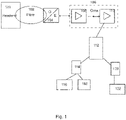
- FIG. 1 shows the general structure of a typical HFC network.
- Program services are introduced from the main amplifier 100 (a so-called headend or CCAP) of the network via an optical fibre network 102 to a fibre node 104, which converts the optical signal to an electric signal to be relayed further in a coaxial cable network 106.
- a node 104 can be an analogue node or a so-called RPD/RMD node.
- this coaxial cable segment typically comprises one or more broadband amplifiers 108, 110 for amplifying program service signals in a heavily attenuating coaxial media.
- the cable network 112 of a smaller area such as a distribution network of an apartment building, which are typically implemented as coaxial tree or star networks comprising signal splitters for distributing the program service signals to each customer.
- the cable network 112 such as the distribution network of an apartment, may further comprise a Network Interface Unit (NIU) or Point of Entry (PoE) device arranged to divide signals to appropriate home appliances.
- the NIU may operate as a home amplifier. From a wall outlet the signal is further relayed either via a cable modem 114 to a television receiver 116 or a computer 118, or via a so-called set-top box 120 to a television receiver 122.
- NIU Network Interface Unit
- PoE Point of Entry
- the HFC network may be implemented according to various standards.
- video transmission in the HFC networks have traditionally been implemented according to DVB-C (Digital Video Broadcasting - Cable) standard, but currently there is an on-going shift to more widely use the DOCSIS (Data Over Cable Service Interface Specification) standard.
- DVB-C Digital Video Broadcasting - Cable
- DOCSIS Data Over Cable Service Interface Specification
- DOCSIS is a CATV standard providing specifications for high-bandwidth data transfer in an existing CATV system.
- DOCSIS may be employed to provide Internet access over existing hybrid fiber-coaxial (HFC) infrastructure of cable television operators.
- HFC hybrid fiber-coaxial
- DOCSIS has been evolved through versions 1.0, 1.1, 2.0, 3.0 and 3.1 to the latest version of 4.0.
- the headend 100 of the CATV network comprises inputs for signals, such as TV signals and IP signals, a television signal modulator and a cable modem termination system (CMTS).
- CMTS provides high-speed data services to customers thorough cable modems (CM; 114) locating in homes.
- CM cable modems
- the CMTS forms the interface to the IP-based network over the Internet. It modulates the data from the Internet for downstream transmission to homes and receives the upstream data from homes.
- the CMTS additionally manages the load balancing, error correction parameters and the class of service (CoS).
- Signals from the headend 100 are distributed optically (fiber network 102) to within the vicinity of individual homes, where the optical signals are converted to electrical signals at the terminating points 104.
- the electrical signals are then distributed to the various homes via the existing 75 ohm coaxial cables 106.
- the maximum data transfer of the coaxial cables is limited due to strong frequency-based attenuation. Therefore, the electrical signals transmitted over coaxial cables must be amplified.
- the amplifiers 108, 110 used for this purpose are suited to a specific frequency range.
- the upstream and downstream must occur over the same physical connection.
- the last part 112 of the coaxial connection between the CMTS and the CMs branches off in a star or a tree structure.
- a CMTS transmits the same data to all CMs located along the same section of cable (one-to-many communications).
- a request/grant mechanism exists between the CMTS and the CMs, meaning that a CM needing to transmit data must first send a request to the CMTS, after which it can transmit at the time assigned to it.
- the upstream channel width may vary between 200 kHz and 3.2 MHz (versions 1.0/1.1), and even to 6.4 MHz (version 2.0).
- DOCSIS 3.1 specifications support capacities of at least 10 Gbit/s downstream and 1 Gbit/s upstream using 4096 QAM.
- DOCSIS 3.1 rejects the 6 or 8 MHz wide channel spacing and uses narrower orthogonal frequency-division multiplexing (OFDM) subcarriers being 20 kHz to 50 kHz wide, which sub-carriers can be combined within a block spectrum of maximum of 192MHz wide.
- OFDM orthogonal frequency-division multiplexing
- DOCSIS 3.1 further provides the concept of Distributed CCAP Architecture (DCA).
- Converged Cable Access Platform (CCAP) may be defined as an access-side networking element or set of elements that combines the functionality of a CMTS with that of an Edge QAM (i.e. the modulation), providing high-density services to cable subscribers.
- CCAP Converged Cable Access Platform
- the CCAP functionalities have been implemented in the headend/hub, such as the headend 100 in Figure 1 .
- some features of the CCAP are distributed from headend/hub to the network elements closer to the customers, for example to the fibre nodes 104 in Figure 1 .
- the CCAP functionalities left to be implemented in the headend/hub may be referred to as CCAP core.
- DOCSIS 3.1 specifies at least two network element concepts, i.e. a Remote PHY Device (RPD) and a Remote-MACPHY Device (RMD), to which some functionalities of the headend can be distributed.
- RPD Remote PHY Device
- RMD Remote-MACPHY Device
- a recent version of DOCSIS 3.1 specification also provided Annex F introducing a Full Duplex DOCSIS 3.1 technology, where a new distributed access node called Full Duplex (FDX) Node is determined.
- FDX Full Duplex
- DOCSIS 3.1 and 4.0 One issue relating to the introduction of DOCSIS 3.1 and 4.0 is the need to eventually adjust the frequency range and the bandwidth of the communication channels to meet the requirements of faster communication.
- the older DOCSIS standards up to the version 3.0 provide an upstream bandwidth of 5 - 42 MHz (in Americas) or 5 - 65 MHz (in Europe) and a downstream bandwidth of 85 - 862 MHz or even up to 1.0 GHz.
- DOCSIS 3.1 introduces a downstream band up to 1218 MHz.
- the upper frequency edge of the upstream bandwidth is raised to 204 MHz, causing the lower frequency edge of the downstream bandwidth to be raised to 258 MHz.
- DOCSIS 4.0 will shift the upper frequency edge of the upstream bandwidth even to 684 MHz, whereupon the lower frequency edge of the downstream bandwidth to be raised to 834 MHz.
- the operational principle of the RF amplifiers is similar in that sense that they must be capable of two-way transmission and amplification of both downstream and upstream (a.k.a. forward path and return path) signals.
- CATV amplifiers typically need to support several different upstream-downstream frequency splits, such as 42/54 MHz, 65/85 MHz, 85/108 MHz, 204/258 MHz, 300/372 MHz, 396/492 MHz, 492/606 MHz or 684/834 MHz. This may be actualized, for example, with one or more diplex filters, such as plug-in diplex filters, and return path modules for each individual split.
- diplex filters such as plug-in diplex filters, and return path modules for each individual split.
- the alignment of upstream path components of the CATV amplifier has been rather simple.
- the attenuation in the coaxial cable may increase significantly. This causes challenges for adjusting the gain, slope and/or attenuation parameters of the upstream channel components of the CATV amplifier such that the signal-to-noise ratio (SNR) of the upstream signal remains good.
- SNR signal-to-noise ratio
- the CATV amplifiers typically have an input amplifier stage and an output amplifier stage provided with an output attenuator and an output equalizer, but there are no mid-stage controls.
- the output amplifier stage is typically configured to provide a maximum signal level, because the input level of the next CATV amplifier along the network is fixed. However, operating the output amplifier stage close to its maximum values typically causes high power consumption, as well as distortion products possibly degrading the output signal quality.
- FIG. 2 shows an example of some return path (i.e. upstream) components of the CATV amplifier, where the upstream signal is provided to an input amplifier stage 200.
- the amplified input signal is fed to a fixed slope control unit 202.
- the return path comprises a mid-stage attenuator 204 and an optional mid-stage equalizer 206. Thereafter, the signal is amplified by an output amplifier stage 208, and adjusted by an output attenuator 210 and an output equalizer 212.
- the attenuation is divided in two different units, and maximum level at the output can be avoided by allocating a majority, or at least a significant share, of the attenuation to the mid-stage attenuator.
- noise figure NF1 defined as 10 log 10 (SNR i /SNR o ), where SNR i and SNR o are the input and output signal-to-noise ratios
- SNR i and SNR o are the input and output signal-to-noise ratios
- the amount of slope applied by a CATV amplifier on the return path has been traditionally low, because the cable attenuation on 42/65/85/204 MHz return paths is not significant. However, in future higher slope values will be used due to the introduction of higher frequency bandwidths on the return paths, such as up to 684 MHz. If the return path comprises a mid-stage equalizer and if the adjustment for the higher slope value is performed primarily in the mid-stage equalizer, the noise figure NF of the whole upstream amplifier path at the lower frequency edge of upstream signal bandwidth may become high, since the noise figure NF2 of the output amplifier stage has more impact. It is noted that noise figure NF2 of the output amplifier stage has no practical role as long as the input level for output amplifier is significantly higher than input level of input amplifier.
- a field technician aiming to align the return path of a CATV amplifier having a fixed slope, and a mid-stage equalizer and a mid-stage attenuator used in mid-stage position will inevitably face great challenges in aligning the amplifier so that there is optimal amount of attenuation and slope used in mid-stage.
- the alignments of both the mid-stage equalizer and the mid-stage attenuator create attenuation at low frequencies and there is a risk that SNR at the low edge of the return path frequency band may be ruined.
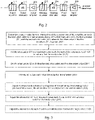
- a method for controlling upstream signal path components of an amplifier of a cable television (CATV) network element as illustrated in Figure 3 , wherein the upstream signal path components comprise at least a first and a second amplifier stage, a first attenuator and a first equalizer between the first and the second amplifier stage, and a second attenuator after the second amplifier stage in upstream signal path direction, the method comprising: determining (300) a target value for total attenuation of the components of the amplifier, wherein the total attenuation is a sum of attenuations of the first attenuator (A1), the first equalizer (S1), and the second attenuator (A2), wherein the attenuation of the first equalizer (S1) is preset; setting (302) the attenuation of the first attenuator (A1) to a maximum value such the sum of the attenuations of the first attenuator (A1) and the first equalizer (S1) is below a first threshold value
- the first attenuator and the first equalizer may refer, for example, to the mid-stage attenuator and the mid-stage equalizer
- the second attenuator may refer, for example, to the output attenuator, as shown in Figure 2
- the CATV amplifier may further comprise the output equalizer, as shown in Figure 2 , as a second equalizer, but this is not mandatory. Accordingly, when adjusting the gain of the CATV amplifier in view of aiming to provide the next CATV amplifier in the network with an input signal with a fixed signal level and a flat frequency response, there typically arises a need to adjust the attenuation provided by the upstream components. Thus, a target value is determined for the total attenuation of the components of the amplifier, wherein the target value may be such that the output signal of CATV amplifier reaches a predetermined signal level.
- the predetermined signal level of the output signal may be linked to the desired level of the input signal to the next CATV amplifier in the network. That is, when applying the unity gain method in the amplifier alignment, the purpose is to provide the next CATV amplifier with an input signal with a fixed signal level equal to the input signal level of the previous CATV amplifier and with a flat frequency response. Since the coaxial cable and possible other components between the CATV amplifiers inevitably cause some attenuation, the predetermined signal level of the output signal is preferably higher than desired input signal level of the CATV amplifiers so as to compensate the attenuation.
- the total attenuation is a sum of attenuation components provided by the first attenuator, the first equalizer, the second attenuator and the optional second equalizer.
- the attenuation components of the first attenuator and the second attenuator, i.e. A1 and A2 are not frequency-dependent, i.e. they typically attenuate same amount over the whole frequency band, wherein the amount of attenuation between A1 and A2 may naturally vary.
- the attenuation components of the first equalizer and the optional second equalizer, i.e. S1 and S2 are frequency-dependent such that the lower frequencies have the highest attenuation and the highest frequency has typically 0 dB attenuation.
- the equalizers have a frequency response, a.k.a. slope or tilt, that is opposite to a normal attenuation curve of a coaxial cable.
- the attenuations of the first equalizer (S1) and the second equalizer (S2) may be initially preset to a default value.
- the attenuation of the first attenuator (A1) is set to a maximum value such the sum of the attenuations of the first attenuator (A1) and the first equalizer (S1) is below a first threshold value, and the attenuation of the second attenuator (A2) is set such that the total attenuation reaches the target value.
- the CATV amplifier can be aligned in a more optimal way by using the mid-stage controls and their attenuations S1 and A1 together with the output controls and their attenuations S2 and A2.
- the output level of output amplifier stage can be lowered, and the problem created by distortion products and power consumption can be alleviated.
- the noise figure NF2 of the output amplifier stage starts to have negative impact on SNR.
- This is controlled by preventing the sum of the attenuations of the first attenuator (A1) and the first equalizer (S1) to exceed the first threshold value. In other words, an appropriate balance is controlled between the mid-stage controls S1 and A1 and the output controls S2 and A2.
- the method further comprises adjusting (308), in response to a frequency response of the output signal deviating from a predetermined slope value, the attenuation of the first equalizer (S1) to compensate for said deviation; adjusting (310) the attenuation of the first attenuator (A1) to a maximum value such the sum of the attenuations of the first attenuator (A1) and the first equalizer (S1) is below said first threshold value; and adjusting (312) the attenuation of the second attenuator (A2) such that the total attenuation reaches the target value.
- the output signal shall also preferably have a predetermined slope value.
- the purpose is to provide the next CATV amplifier with an input signal, besides with a fixed signal level, but also with a flat frequency response. Therefore, in order to compensate for the frequency-dependent attenuation caused at least by the coaxial cable between the CATV amplifiers, the output signal preferably has a compensating predetermined slope value.
- the attenuation of the first equalizer may be adjusted to compensate for the deviation in the frequency response.
- adjusting the attenuation of the first equalizer (S1) also leads to adjusting the attenuation of the first attenuator to the maximum value such the sum of A1 and S1 is below said first threshold value.
- the attenuation of the second attenuator (A2) shall be adjusted so that the total attenuation reaches the target value.
- the upstream signal path components further comprise a second equalizer having a preset attenuation (S2) affecting to the total attenuation and a maximum allowable value is set for the attenuation of the first equalizer (S1)
- the method further comprises adjusting, in response to a frequency response of the output signal deviating from the predetermined slope value and the attenuation of the first equalizer (S1) has reached its maximum allowable value, the attenuation of the second equalizer (S2) to compensate for said deviation; adjusting the attenuation of the first attenuator (A1) to a maximum value such the sum of the attenuations of the first attenuator (A1) and the first equalizer (S1) is below said first threshold value; and adjusting the attenuation of the second attenuator (A2) such that the total attenuation reaches the target value.
- S2 preset attenuation
- the aim of keeping the sum of A1 and S1 to be below said first threshold value may, at least in part, be implemented such that a maximum allowable value is set for the attenuation of the first equalizer (S1).
- the attenuation of the second equalizer (S2) is increased to compensate for the deviation in the output signal from the predetermined slope value.
- the method further comprises adjusting, prior to determining the target value for the total attenuation, the sum of the gain (G1) of the first amplifier stage and the gain (G2) of the second amplifier stage of the amplifier to a predetermined level.
- the sum of the gain (G1) of the first amplifier stage and the gain (G2) of the second amplifier stage (G2)of the CATV amplifier is preferably adjusted to a predetermined level.
- the raw gain G1+ G2 is then affected by the applied attenuations, such as A1, A2, S1, S2 as described above, but also by other passive losses on the return path route inside the CATV amplifier.
- the operational gain of the CATV amplifier, reflecting to the output signal level is much lower than the raw gain because of several losses and adjustments.
- the gain of the input amplifier stage (G1) can be made higher than the gain of the output amplifier stage (G2). This enables, in the initial phase of the adjustment process, to ignore the noise figure NF2 of the output amplifier stage as negligible due to the input level for output amplifier being significantly higher than input level of input amplifier. This, in turn, enables to focus to the optimization to allocating as great share of the attenuation as possible to the mid-stage attenuator, and monitoring the possible increase of the noise figure NF1 only.
- the gain G1 of the input amplifier stage shall not be adjusted too high, since it may create distortion.
- said first threshold value is lower than the gain of the first amplifier stage (G1).
- the first threshold value which is set as the maximum allowable value for the sum of the attenuations of the first attenuator (A1) and the first equalizer (S1), operates to prevent the input level of the output amplifier stage to decrease too much.
- the first threshold value is set lower than the gain of the first amplifier stage (G1).
- the sum A1+S1 shall not reach the gain of the first amplifier stage (G1), thereby ensuring that the noise figure NF2 of the output amplifier stage remains to have negligible impact on SNR.
- CATV amplifier may involve other attenuating elements (in addition to S1 and A1) between the amplifier stages that also create attenuation.
- attenuation elements may involve e.g. a flatness correction unit, a test point, a transponder signal injection point, etc.
- the attenuation of said elements must be taken in account when calculating said sum.
- said target value for the total attenuation of the components of the amplifier is determined at low frequencies of the upstream frequency band, such as within a range of 5 - 65 MHz.
- said target value for the total attenuation of the components of the amplifier is determined at low frequencies of the upstream frequency band, such as within a range of 5 - 65 MHz.
- a network element of a cable television (CATV) network comprising at least a first and a second upstream amplifier stage, a first attenuator and a first equalizer between the first and the second amplifier stage, and a second attenuator after the second upstream amplifier stage in upstream signal path direction; means for determining a target value for total attenuation of the components of the amplifier, wherein the total attenuation is a sum of attenuations of the first attenuator (A1), the first equalizer (S1), and the second attenuator (A2), wherein the attenuation of the first equalizer (S1) is preset; means for setting the attenuation of the first attenuator (A1) to a maximum value such the sum of the attenuations of the first attenuator (A1) and the first equalizer (S1) is below a first threshold value; means for setting the attenuation of the second attenuator (A2) such that the total
- FIG. 4 shows a simplified block chart of a network element (node), wherein the embodiments may be implemented.
- the node 400 comprises a first input/output port 402, which operates as an input for the downstream signals originating from the headend or the CMTS or the CCAP core and an output for the upstream signals originating from the customer devices.
- the node 400 further comprises a second input/output port 404, which operates as an output for the downstream signals originating from the headend or the CMTS and an input for the upstream signals originating from the customer devices.
- Both ports 402, 404 are provided with at least one diplex filter 406 and 408, respectively, for filtering the downstream signals and the upstream signals to their respective frequency bands and splitting the downstream and upstream signals to their own signal routes 410a, 410b travelling at least partly through different components within the node.
- Most of the internal structure of the network element is irrelevant for the implementation of the embodiments, and therefore especially the components of the downstream signal path are only depicted with the reference number 410a.
- the upstream signal path 410b comprises a first upstream amplifier stage 412, which may also be referred to as an input amplifier stage.
- the upstream signal path 410b comprises a first attenuator 414 and a first equalizer 416, also referred to as mid-stage attenuator and mid-stage equalizer.
- the upstream signal path 410b comprises a second upstream amplifier stage 418, also referred to as an output amplifier stage.
- a second attenuator 420 also referred to as the output attenuator, is provided after the second upstream amplifier stage 418 in the upstream signal path direction.
- the exemplified network element of Figure 4 also shows the optional second equalizer 422, also referred to as the output equalizer.
- the network element 400 comprises a control circuit 424 configured to determine a target value for total attenuation of the components of the amplifier.
- the target value for the total attenuation of the components of the network element is determined that the output signal of CATV amplifier reaches a predetermined signal level.
- the predetermined signal level is preferably such that it provides the next CATV amplifier in the network with an input signal with a fixed signal level.
- the control circuit 424 may obtain the predetermined signal level e.g. from a memory 426 of the network element, where the predetermined signal level may be stored as a default value.
- a field technician may supply a value for the predetermined signal level, for example, via the user interface 428 of the network element.
- the supplied predetermined signal level value may be dependent e.g. on the length of the coaxial cable segment to the next CATV amplifier.
- the target value for total attenuation of the upstream components is dependent on the predetermined signal level value at the output and the total gain of the first and the second amplifier stages.
- the control circuit 424 may obtain the gain G1 of the first amplifier stage 412 and the gain G2 of the second amplifier stage 418 e.g. directly from the amplifier stages 412, 418 or from the memory 426.
- a first threshold value may be e.g. stored in the memory 426, wherein the purpose the first threshold value is to prevent the sum of the attenuations of the first attenuator (A1) and the first equalizer (S1) to exceed a level where the input level of the output amplifier stage is decreased too much.
- the purpose is to prevent the noise figure NF2 of the output amplifier stage from having too much negative impact on SNR.
- the total attenuation of the upstream components is a sum of attenuations A1, S1, A2 (and possibly S2) of the first attenuator 414, the first equalizer 416, the second attenuator 420 and the optional second equalizer 422, respectively.
- the attenuations S1 and S2 of the first and the optional second equalizers are typically preset.
- the control circuit 424 is configured to set the attenuation A1 of the first attenuator 414 to a maximum value such the sum of the attenuations A1 and S1 of the first attenuator and the first equalizer is still below the first threshold value. Then the control circuit 424 is configured to set the attenuation A2 of the second attenuator 420 such that the total attenuation reaches the target value.
- the upstream signal which is now preferably at the predetermined level, may be supplied via the first diplex filter 406 and the first input/output port 402 towards the next CATV amplifier in the network.
- the network element 400 may comprise a sampling unit 430 for sampling the upstream signal, for example, before supplying it to the first diplex filter 406.
- the sampling unit may be implemented, at simplest, as a directional coupler, for example.
- the sampling unit 430 provides the control circuit 424 with a sampling signal, based on which the control circuit 424 may determine if further adjustments of first and/or the second attenuators 414, 420 is needed. If yes, the control circuit 424 is configured to carry out the further adjustments so as to output the upstream signal at the predetermined level.
- the output upstream signal should preferably have a predetermined slope value so as compensate for the frequency-dependent attenuation caused at least by the coaxial cable between the CATV amplifiers, thereby providing the next CATV amplifier with an input signal, besides with a fixed signal level, but also with a flat frequency response.
- the control circuit 424 is configured, according to an embodiment, to adjust the attenuation (i.e. the slope) S1 of the first equalizer 416 to compensate for said deviation. While this affects to the sum of A1+S1, the control circuit 424 is configured to adjust the attenuation A1 of the first attenuator 414 to a maximum value such the sum of the attenuations A1 and S1 of the first attenuator 414 and the first equalizer 416 is below said first threshold value.
- control circuit 424 is configured to adjust the attenuation A2 of the second attenuator 420 such that the total attenuation reaches the target value.
- the upstream output signal is now adjusted to a predetermined level and with a predetermined slope value so that the next CATV amplifier is provided with an input signal with a fixed signal level and with a flat frequency response.
- the control circuit 424 is configured to adjust the attenuation S2 of the second equalizer 422 to compensate for said deviation. While this affects to the total attenuation, the control circuit 424 is configured to repeat the above steps, i.e.
- the network element comprises means for adjusting, prior to determining the target value for the total attenuation, total gain of the amplifier to a predetermined level.
- the control circuit 424 may be configured to adjust, prior to determining the target value for the total attenuation, total gain of the amplifier to a predetermined level.
- the need for the attenuation is dependent from the total gain of the amplifier, i.e. the gain components G1 of the first amplifier stage 412 and G2 of the second amplifier stage 418.
- the control circuit 424 may obtain the gain values G1 and G2 from the memory 426, where they could be set as default values.
- the gain values G1 and G2 may be set, e.g. by a field technician, via the user interface 428 of the network element and provided to the control circuit 424.
- the above considerations about the noise figures NF1 and NF2 are preferably taken into account.
- control circuit 424 is configured to adjust said first threshold value to be lower than the gain G1 of the first amplifier stage 414. Consequently, for ensuring that the input level of the output amplifier stage remains higher than the input level of the input amplifier stage, the first threshold value is set lower than the gain G1 of the first amplifier stage.
- control circuit 424 is configured to determine said target value for the total attenuation of the components of the amplifier at low frequencies of the upstream frequency band, such as within a range of 5 - 65 MHz.
- the network element comprises a computer program code, stored in a non-transitory memory means, for controlling the control circuit to carry out said adjustments.
- the logic underlying the embodiments may be implemented by a computer program executing an algorithm for the adjustments.
- the computer program code may be stored, e.g. in the memory 426, or it may be stored in a separate memory.
- the control circuit 424 may be implemented as a central processing unit (CPU), i.e. a microprocessor, and it may be configured to execute the computer program code.
- the network element may comprise a separate CPU for execute the computer program code and providing the control signals to the control circuit 424.
- the embodiments may be illustrated by the following example.
- the total gain of the amplifier i.e. the sum G1 + G2
- the first threshold value i.e. the maximum allowable value for the sum of the attenuations A1 + S1 of the first attenuator 414 and the first equalizer 416, is set as 10 dB. Consequently, 10 dB attenuation is allocated by the algorithm to the first attenuator 414, and 12 dB attenuation is allocated to the second attenuator 420.
- the algorithm preferably ensures that maximum allowable value for the sum of the attenuations A1+ S1 of the mid-stage controls, i.e. the first attenuator 414 and the first equalizer 416, is used. It is noted that if the network element comprises the second equalizer 422, the possible slope adjustment may be divided between the first and the second equalizer, as described above.
- the various embodiments may be implemented in hardware or special purpose circuits or any combination thereof. While various embodiments may be illustrated and described as block diagrams or using some other pictorial representation, it is well understood that these blocks, apparatus, systems, techniques or methods described herein may be implemented in, as non-limiting examples, hardware, software, firmware, special purpose circuits or logic, general purpose hardware or controller or other computing devices, or some combination thereof.
- the implementation may include a computer readable storage medium stored with code thereon for use by an apparatus, such as the network element, which when executed by a processor, causes the apparatus to perform the various embodiments or a subset of them.
- the implementation may include a computer program embodied on a non-transitory computer readable medium, the computer program comprising instructions causing, when executed on at least one processor, at least one apparatus to perform the various embodiments or a subset of them.
- an apparatus may comprise circuitry and electronics for handling, receiving and transmitting data, computer program code in a memory, and a processor that, when running the computer program code, causes the apparatus to carry out the features of an embodiment.
Landscapes
- Engineering & Computer Science (AREA)
- Signal Processing (AREA)
- Multimedia (AREA)
- Computer Networks & Wireless Communication (AREA)
- Power Engineering (AREA)
- Two-Way Televisions, Distribution Of Moving Picture Or The Like (AREA)
- Finger-Pressure Massage (AREA)
- Agricultural Chemicals And Associated Chemicals (AREA)
- Financial Or Insurance-Related Operations Such As Payment And Settlement (AREA)
Applications Claiming Priority (1)
| Application Number | Priority Date | Filing Date | Title |
|---|---|---|---|
| FI20215478A FI129936B (en) | 2021-04-23 | 2021-04-23 | An arrangement for aligning upstream path |
Publications (3)
| Publication Number | Publication Date |
|---|---|
| EP4080876A1 true EP4080876A1 (de) | 2022-10-26 |
| EP4080876C0 EP4080876C0 (de) | 2025-10-01 |
| EP4080876B1 EP4080876B1 (de) | 2025-10-01 |
Family
ID=81074086
Family Applications (1)
| Application Number | Title | Priority Date | Filing Date |
|---|---|---|---|
| EP22165776.0A Active EP4080876B1 (de) | 2021-04-23 | 2022-03-31 | Anordnung zum ausrichten eines stromaufwärtigen weges |
Country Status (3)
| Country | Link |
|---|---|
| US (1) | US11595733B2 (de) |
| EP (1) | EP4080876B1 (de) |
| FI (1) | FI129936B (de) |
Families Citing this family (1)
| Publication number | Priority date | Publication date | Assignee | Title |
|---|---|---|---|---|
| AU2024212149A1 (en) * | 2023-01-26 | 2025-07-31 | Arris Enterprises Llc | Amplifier for extended spectrum docsis |
Citations (2)
| Publication number | Priority date | Publication date | Assignee | Title |
|---|---|---|---|---|
| EP0928063A2 (de) * | 1998-01-02 | 1999-07-07 | Thomas & Betts International, Inc. | Breitband-Kabelfernsehverstärker mit mikroprozessorgesteuerter Anstiegs- und Verstärkungsregelung |
| EP1936977A2 (de) * | 2006-12-22 | 2008-06-25 | Teleste Oyj | Verstärkungssteuerung eines Breitbandverstärkers |
Family Cites Families (5)
| Publication number | Priority date | Publication date | Assignee | Title |
|---|---|---|---|---|
| US6836184B1 (en) | 1999-07-02 | 2004-12-28 | Adc Telecommunications, Inc. | Network amplifier with microprocessor control |
| US7375876B2 (en) * | 2004-12-21 | 2008-05-20 | Nec Corporation | Optical transmitting apparatus having variable optical transmitting unit including plurality of paths |
| JP5239141B2 (ja) * | 2006-09-26 | 2013-07-17 | 富士通株式会社 | 光増幅装置およびその制御方法 |
| US10396737B2 (en) | 2016-11-11 | 2019-08-27 | Skyworks Solutions, Inc. | Wide dynamic range amplifier system |
| US10938444B2 (en) | 2019-07-12 | 2021-03-02 | Avago Technologies International Sales Pte. Limited | Apparatus and method for noise reduction in a full duplex repeater |
-
2021
- 2021-04-23 FI FI20215478A patent/FI129936B/en active
-
2022
- 2022-03-31 EP EP22165776.0A patent/EP4080876B1/de active Active
- 2022-04-15 US US17/721,559 patent/US11595733B2/en active Active
Patent Citations (2)
| Publication number | Priority date | Publication date | Assignee | Title |
|---|---|---|---|---|
| EP0928063A2 (de) * | 1998-01-02 | 1999-07-07 | Thomas & Betts International, Inc. | Breitband-Kabelfernsehverstärker mit mikroprozessorgesteuerter Anstiegs- und Verstärkungsregelung |
| EP1936977A2 (de) * | 2006-12-22 | 2008-06-25 | Teleste Oyj | Verstärkungssteuerung eines Breitbandverstärkers |
Also Published As
| Publication number | Publication date |
|---|---|
| US20220345788A1 (en) | 2022-10-27 |
| FI20215478A1 (en) | 2022-10-24 |
| FI129936B (en) | 2022-11-15 |
| EP4080876C0 (de) | 2025-10-01 |
| US11595733B2 (en) | 2023-02-28 |
| EP4080876B1 (de) | 2025-10-01 |
Similar Documents
| Publication | Publication Date | Title |
|---|---|---|
| EP3707831B1 (de) | Anordnung für catv-netzwerksegmentierung | |
| US11595733B2 (en) | Arrangement for aligning upstream path | |
| US10841009B2 (en) | Arrangement for CATV network | |
| US20230199265A1 (en) | Arrangement for enhancing downstream performance | |
| EP3707833B1 (de) | Anordnung für catv-netzwerksegmentierung | |
| US20210265954A1 (en) | An arrangement for catv amplifier control | |
| US12206953B2 (en) | Arrangement for adjusting frequency response | |
| US12149863B2 (en) | Arrangement for controlling power consumption | |
| EP3741106A1 (de) | Anordnung zur verstärkungseinstellung | |
| EP3815270B1 (de) | Anordnung für catv-verstärkersteuerung | |
| CA3080940C (en) | An arrangement for catv network segmentation | |
| FI131543B1 (en) | Determining network topology | |
| WO2020157370A1 (en) | A method for adjusting parameters of a network element | |
| WO2020128135A1 (en) | A method for adjusting parameters of a network element | |
| CA3104066C (en) | An arrangement for catv amplifier control |
Legal Events
| Date | Code | Title | Description |
|---|---|---|---|
| PUAI | Public reference made under article 153(3) epc to a published international application that has entered the european phase |
Free format text: ORIGINAL CODE: 0009012 |
|
| STAA | Information on the status of an ep patent application or granted ep patent |
Free format text: STATUS: THE APPLICATION HAS BEEN PUBLISHED |
|
| AK | Designated contracting states |
Kind code of ref document: A1 Designated state(s): AL AT BE BG CH CY CZ DE DK EE ES FI FR GB GR HR HU IE IS IT LI LT LU LV MC MK MT NL NO PL PT RO RS SE SI SK SM TR |
|
| STAA | Information on the status of an ep patent application or granted ep patent |
Free format text: STATUS: REQUEST FOR EXAMINATION WAS MADE |
|
| 17P | Request for examination filed |
Effective date: 20230420 |
|
| RBV | Designated contracting states (corrected) |
Designated state(s): AL AT BE BG CH CY CZ DE DK EE ES FI FR GB GR HR HU IE IS IT LI LT LU LV MC MK MT NL NO PL PT RO RS SE SI SK SM TR |
|
| STAA | Information on the status of an ep patent application or granted ep patent |
Free format text: STATUS: EXAMINATION IS IN PROGRESS |
|
| 17Q | First examination report despatched |
Effective date: 20230922 |
|
| RAP1 | Party data changed (applicant data changed or rights of an application transferred) |
Owner name: TELESTE NETWORKS OY |
|
| REG | Reference to a national code |
Ref country code: DE Ref legal event code: R079 Free format text: PREVIOUS MAIN CLASS: H04N0007173000 Ipc: H03F0003189000 Ref document number: 602022022128 Country of ref document: DE |
|
| GRAP | Despatch of communication of intention to grant a patent |
Free format text: ORIGINAL CODE: EPIDOSNIGR1 |
|
| STAA | Information on the status of an ep patent application or granted ep patent |
Free format text: STATUS: GRANT OF PATENT IS INTENDED |
|
| RIC1 | Information provided on ipc code assigned before grant |
Ipc: H04L 12/28 20060101ALI20250502BHEP Ipc: H04N 21/61 20110101ALI20250502BHEP Ipc: H04N 7/10 20060101ALI20250502BHEP Ipc: H04N 7/173 20110101ALI20250502BHEP Ipc: H03G 9/00 20060101ALI20250502BHEP Ipc: H03F 3/189 20060101AFI20250502BHEP |
|
| INTG | Intention to grant announced |
Effective date: 20250526 |
|
| GRAS | Grant fee paid |
Free format text: ORIGINAL CODE: EPIDOSNIGR3 |
|
| GRAA | (expected) grant |
Free format text: ORIGINAL CODE: 0009210 |
|
| STAA | Information on the status of an ep patent application or granted ep patent |
Free format text: STATUS: THE PATENT HAS BEEN GRANTED |
|
| AK | Designated contracting states |
Kind code of ref document: B1 Designated state(s): AL AT BE BG CH CY CZ DE DK EE ES FI FR GB GR HR HU IE IS IT LI LT LU LV MC MK MT NL NO PL PT RO RS SE SI SK SM TR |
|
| REG | Reference to a national code |
Ref country code: GB Ref legal event code: FG4D Ref country code: CH Ref legal event code: F10 Free format text: ST27 STATUS EVENT CODE: U-0-0-F10-F00 (AS PROVIDED BY THE NATIONAL OFFICE) Effective date: 20251001 |
|
| REG | Reference to a national code |
Ref country code: DE Ref legal event code: R096 Ref document number: 602022022128 Country of ref document: DE |
|
| REG | Reference to a national code |
Ref country code: IE Ref legal event code: FG4D |
|
| U01 | Request for unitary effect filed |
Effective date: 20251030 |
|
| U07 | Unitary effect registered |
Designated state(s): AT BE BG DE DK EE FI FR IT LT LU LV MT NL PT RO SE SI Effective date: 20251105 |
|
| PG25 | Lapsed in a contracting state [announced via postgrant information from national office to epo] |
Ref country code: ES Free format text: LAPSE BECAUSE OF FAILURE TO SUBMIT A TRANSLATION OF THE DESCRIPTION OR TO PAY THE FEE WITHIN THE PRESCRIBED TIME-LIMIT Effective date: 20251001 |
|
| PG25 | Lapsed in a contracting state [announced via postgrant information from national office to epo] |
Ref country code: NO Free format text: LAPSE BECAUSE OF FAILURE TO SUBMIT A TRANSLATION OF THE DESCRIPTION OR TO PAY THE FEE WITHIN THE PRESCRIBED TIME-LIMIT Effective date: 20260101 |
|
| PG25 | Lapsed in a contracting state [announced via postgrant information from national office to epo] |
Ref country code: HR Free format text: LAPSE BECAUSE OF FAILURE TO SUBMIT A TRANSLATION OF THE DESCRIPTION OR TO PAY THE FEE WITHIN THE PRESCRIBED TIME-LIMIT Effective date: 20251001 |
|
| PG25 | Lapsed in a contracting state [announced via postgrant information from national office to epo] |
Ref country code: RS Free format text: LAPSE BECAUSE OF FAILURE TO SUBMIT A TRANSLATION OF THE DESCRIPTION OR TO PAY THE FEE WITHIN THE PRESCRIBED TIME-LIMIT Effective date: 20260101 |
|
| PG25 | Lapsed in a contracting state [announced via postgrant information from national office to epo] |
Ref country code: IS Free format text: LAPSE BECAUSE OF FAILURE TO SUBMIT A TRANSLATION OF THE DESCRIPTION OR TO PAY THE FEE WITHIN THE PRESCRIBED TIME-LIMIT Effective date: 20260201 |