EP1936977A2 - Verstärkungssteuerung eines Breitbandverstärkers - Google Patents
Verstärkungssteuerung eines Breitbandverstärkers Download PDFInfo
- Publication number
- EP1936977A2 EP1936977A2 EP07397502A EP07397502A EP1936977A2 EP 1936977 A2 EP1936977 A2 EP 1936977A2 EP 07397502 A EP07397502 A EP 07397502A EP 07397502 A EP07397502 A EP 07397502A EP 1936977 A2 EP1936977 A2 EP 1936977A2
- Authority
- EP
- European Patent Office
- Prior art keywords
- amplifier
- network element
- amplification
- signal
- network
- Prior art date
- Legal status (The legal status is an assumption and is not a legal conclusion. Google has not performed a legal analysis and makes no representation as to the accuracy of the status listed.)
- Withdrawn
Links
Images
Classifications
-
- H—ELECTRICITY
- H04—ELECTRIC COMMUNICATION TECHNIQUE
- H04N—PICTORIAL COMMUNICATION, e.g. TELEVISION
- H04N7/00—Television systems
- H04N7/10—Adaptations for transmission by electrical cable
-
- H—ELECTRICITY
- H03—ELECTRONIC CIRCUITRY
- H03G—CONTROL OF AMPLIFICATION
- H03G1/00—Details of arrangements for controlling amplification
-
- H—ELECTRICITY
- H04—ELECTRIC COMMUNICATION TECHNIQUE
- H04N—PICTORIAL COMMUNICATION, e.g. TELEVISION
- H04N21/00—Selective content distribution, e.g. interactive television or video on demand [VOD]
- H04N21/20—Servers specifically adapted for the distribution of content, e.g. VOD servers; Operations thereof
- H04N21/21—Server components or server architectures
-
- H—ELECTRICITY
- H04—ELECTRIC COMMUNICATION TECHNIQUE
- H04N—PICTORIAL COMMUNICATION, e.g. TELEVISION
- H04N21/00—Selective content distribution, e.g. interactive television or video on demand [VOD]
- H04N21/20—Servers specifically adapted for the distribution of content, e.g. VOD servers; Operations thereof
- H04N21/23—Processing of content or additional data; Elementary server operations; Server middleware
-
- H—ELECTRICITY
- H04—ELECTRIC COMMUNICATION TECHNIQUE
- H04N—PICTORIAL COMMUNICATION, e.g. TELEVISION
- H04N21/00—Selective content distribution, e.g. interactive television or video on demand [VOD]
- H04N21/60—Network structure or processes for video distribution between server and client or between remote clients; Control signalling between clients, server and network components; Transmission of management data between server and client, e.g. sending from server to client commands for recording incoming content stream; Communication details between server and client
- H04N21/61—Network physical structure; Signal processing
- H04N21/6106—Network physical structure; Signal processing specially adapted to the downstream path of the transmission network
- H04N21/6118—Network physical structure; Signal processing specially adapted to the downstream path of the transmission network involving cable transmission, e.g. using a cable modem
-
- H—ELECTRICITY
- H04—ELECTRIC COMMUNICATION TECHNIQUE
- H04N—PICTORIAL COMMUNICATION, e.g. TELEVISION
- H04N21/00—Selective content distribution, e.g. interactive television or video on demand [VOD]
- H04N21/60—Network structure or processes for video distribution between server and client or between remote clients; Control signalling between clients, server and network components; Transmission of management data between server and client, e.g. sending from server to client commands for recording incoming content stream; Communication details between server and client
- H04N21/63—Control signaling related to video distribution between client, server and network components; Network processes for video distribution between server and clients or between remote clients, e.g. transmitting basic layer and enhancement layers over different transmission paths, setting up a peer-to-peer communication via Internet between remote STB's; Communication protocols; Addressing
- H04N21/637—Control signals issued by the client directed to the server or network components
- H04N21/6377—Control signals issued by the client directed to the server or network components directed to server
-
- H—ELECTRICITY
- H04—ELECTRIC COMMUNICATION TECHNIQUE
- H04N—PICTORIAL COMMUNICATION, e.g. TELEVISION
- H04N7/00—Television systems
- H04N7/16—Analogue secrecy systems; Analogue subscription systems
- H04N7/173—Analogue secrecy systems; Analogue subscription systems with two-way working, e.g. subscriber sending a programme selection signal
-
- H—ELECTRICITY
- H04—ELECTRIC COMMUNICATION TECHNIQUE
- H04N—PICTORIAL COMMUNICATION, e.g. TELEVISION
- H04N7/00—Television systems
- H04N7/22—Adaptations for optical transmission
Definitions
- the invention relates to cable television network amplifiers, specifically to amplification control of a broadband amplifier.
- Cable television networks may be implemented with various techniques and network topologies, but currently most cable television networks are implemented as so-called HFC networks (Hybrid Fiber Coax), i.e. as combinations of a fibre network and a coaxial cable network.
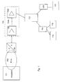
- Figure 1 shows the general structure of a typical HFC network.
- Program services are introduced from the main amplifier 100 (a so-called headend) of the network via an optical fibre network 102 to a fibre node 104, which converts the optical signal to an electric signal to be relayed further in a coaxial cable network 106.
- main amplifier 100 a so-called headend
- a fibre node 104 which converts the optical signal to an electric signal to be relayed further in a coaxial cable network 106.
- a coaxial cable network 106 Depending on the length, branching, topology, etc.
- this coaxial cable portion typically comprises one or more broadband amplifiers 108, 110 for amplifying program service signals in a heavily attenuating coaxial media.
- the program service signals are introduced to a cable network 112 of a smaller area, such as a master antenna network of an apartment building, which are typically implemented as coaxial tree or star networks.
- a master antenna network of an apartment building, which are typically implemented as coaxial tree or star networks.
- the signal is further relayed either via a cable modem 114 to a television receiver 116 or a computer 118, or via a so-called set-top box 120 to a television receiver 122.
- a broadband amplifier typically comprises several attenuators, signal inclination controllers and amplifiers, by means of which both the forward and reverse signals are amplified and, on the other hand, the signal levels are controlled into balance so that noise and distortion of the signal remain within allowed limits.
- the installation of an amplifier requires good professional skills from the personnel, and despite of that, the installation may take an unreasonably long time.
- the invention is based on the idea, that a network element adaptable to a cable television network is implemented, which element comprises several amplifier units for amplifying a forward signal into a desired value and at least one coaxial output connection for the forward signal.
- the network element according to the invention comprises an amplification control point for entering the desired amplification value of the forward signal to the network element; and a processing unit for controlling the parameters of at least some amplifier components comprised by the amplifier units, the values of which parameters are predetermined to be responsive to the entered amplification value
- all the amplifiers of the broadband amplifier are controlled according to a predetermined algorithm so that the person performing the installation selects the desired amplification, for example, on the basis of network topology and network measurements, as response to which amplification setting the microprocessor controls the parameters of each controlled amplification component to a suitable value.
- the network element comprises a computer program stored in a memory, which program comprises a control algorithm for controlling the parameters of said amplifier components, which computer program executed in a processing unit is arranged to receive the entered amplification value; to select a control setting corresponding to the entered amplification value; and to control the parameters of at least some amplifier components comprised by said amplifier units according to the selected control setting.
- the network element also comprises several amplifier units for amplifying a reverse signal to a desired value, in which case said amplification control point is arranged to receive the desired amplification value of the reverse signal; and said processing unit is arranged to control the parameters of at least some amplifier components comprised by the reverse amplifier units to predetermined values as response to the entered amplification value.
- the network element according to the invention provides significant advantages.
- a very significant advantage is that the installation of the broadband amplifier and especially the amplification control of the broadband amplifier becomes significantly faster. Further, a significant advantage is that the personnel performing the installation can be sure that the settings of the amplifier are accurate for other signal parameters besides the amplification as well.
- the procedure according to the invention can be applied not only to amplify the forward signal, but also to amplify the reverse signal.
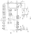
- Figure 2 shows a broadband amplifier according to the invention by means of a simplified block chart.
- the purpose of figure 2 is to illustrate the operation of a broadband amplifier and especially a forward amplification control arrangement implemented in connection with it, and therefore, figure 2 does not necessarily show all the functional blocks of a typical broadband amplifier.
- the amplification control arrangement according to the invention can also be implemented in an amplifier arranged in connection with a fibre node (104 in figure 1 ) of an HFC network, in which case the input connection of the network element comprising the amplifier can be either optical or coaxial, but there is always an coaxial output in the output.
- the amplifier may comprise several output connections, one or more of which can be an active output and one or more can be an output with a passive power supply.
- the route of the forward signal i.e. from the networks to client terminals
- the route of the reverse signal i.e. from the client terminals to the service provider
- the broadband amplifier 200 comprises at least one input port 202, after which has been arranged a tap for a test point 204 of the input signal. After the test point 204 of the input signal an input diplexer 206 has been arranged on the signal route, which directs the forward signal in the direction pointed by the arrow A, and the reverse signal to the direction pointed by the arrow B.
- a broadband amplifier typically comprises several, for example 3 to 7 such combinations of an attenuator, signal inclination controller and amplifier, by means of which the forward signal is amplified, and on the other hand the signal levels are controlled into balance so that noise and distortion of the signal remain within allowed limits.
- the broadband amplifier may advantageously comprise a micro processor 214, which controls the parameters of the above-mentioned blocks, for example, on the basis of different measurement results.
- the amplified and controlled forward signal output from the last amplifier is introduced to a directional coupler 216, which enables sampling from the forward signal in order to measure signal levels.
- the signal samples are introduced to a transponder unit 218, which comprises an interference level indicator 218a, for example a controllable RF indicator, and a transceiver unit 218b, advantageously a modem.
- the transponder unit inputs the samples further to the micro processor 214 to be analyzed, and on the basis of the analysis results the micro processor 214 controls the above-mentioned attenuators, signal inclination controllers and amplifiers to a suitable level.
- the signal is introduced to an output diplexer 220, which operates in a corresponding manner as the input diplexer, and from there further to a tap for a test point 222 of the output signal.
- the broadband amplifier comprises at least one, but advantageously several coaxial output ports 224.
- the broadband amplifier comprises, similarly to the forward signal path, attenuators, signal inclination controllers and amplifiers for controlling the reverse signal to a suitable level.
- the reverse signal route comprises an amplifier 226 arranged after an output diplexer 220, in connection with which amplifier is arranged a tap 228 for the test point of the reverse signal, as well as a directional coupler, by means of which it is possible to enter samples from the reverse signal to a controllable RF indicator 218a comprised by a transponder unit 218, and further to a micro processor 214 to be analyzed.
- the reverse signal route may comprise one or more attenuators 230, 236, a second amplifier 234, a signal inclination controller 238 and a reverse signal interruption point 232.
- the present invention relates especially to amplification control of a forward signal (signal route A), but according to an embodiment the same principle can also be applied for amplification of a reverse signal, as will be described later.
- the broadband amplifier used in cable television networks comprises several, typically at least two of the above-described combinations of an attenuator, a signal inclination controller and an amplifier, which combinations may be called amplifier units ( figure 2 shows three amplifier units).
- the number of amplifier units depends on how high an amplification is desired from the broadband amplifier, when necessary. If, for example, an amplification of 40 dB is desired, at least two amplifier units are needed, but in practice, however, more, even four amplifier units.
- the broadband amplifier comprises, for example stored in a memory 240, advantageously in a functional connection with a micro processor 214, a computer program comprising a control algorithm, in which program each amplification value has a predetermined, optimized control setting for each amplification component to be controlled.
- a control algorithm in which program each amplification value has a predetermined, optimized control setting for each amplification component to be controlled.
- control setting 1 that corresponds to a 40 dB amplification
- control setting 2 that corresponds to a 39 dB amplification
- control setting 3 that corresponds to a 38 dB amplification
- the control settings are advantageously pre-optimized in relation to the parameters of the amplification components so that the amplification components create the desired amplification and at the same time the noise and distortion of the signal do not exceed the allowable levels.
- the broadband amplifier further comprises a control point 242 for entering the desired amplification to for the broadband amplifier.
- This control point 242 can be implemented in a variety of ways: it may be, for example, an independent user interface in the broadband amplifier, an access point for a portable computer, through which the setting is provided, or it may simply be one or more electro-mechanical selection switches.
- the person performing the installation enters the desired amplification value, for example 39 dB, via the control point 242 to the amplifier, as a response to which the computer program comprising the control algorithm and performed by a micro processor 214 first selects the control setting corresponding to the entered amplification value, in this case control setting 2, and after that controls the parameter values of the amplification components to values according to the control setting.
- the broadband amplifier also comprises another control algorithm, where a predetermined, optimized control setting for each controllable amplification component exists for each reverse amplification value.
- the reverse control algorithm is typically simpler to implement, because the broadband amplifier usually comprises less amplification components for an reverse signal.
- the reverse amplification control can be implemented by controlling the attenuators 230 and 236 according to the control setting determined on the basis of the control algorithm.
- the person performing the installation enters the desired reverse amplification value to the amplifier via the control point 242, as a response to which said second control algorithm first selects the control setting corresponding to the entered amplification value, and after that controls the parameter values of the attenuators 230 and 236 to values according to the control setting.
- performing the installation of a broadband amplifier becomes significantly faster and especially the time used for controlling the amplification of the broadband amplifier decreases at the best to a fraction of what it was earlier.
- the personnel performing the installation can be sure that the controls of the amplifier are accurate for other signal parameters besides the amplification as well.
Landscapes
- Engineering & Computer Science (AREA)
- Multimedia (AREA)
- Signal Processing (AREA)
- Two-Way Televisions, Distribution Of Moving Picture Or The Like (AREA)
- Input Circuits Of Receivers And Coupling Of Receivers And Audio Equipment (AREA)
- Amplifiers (AREA)
Applications Claiming Priority (1)
| Application Number | Priority Date | Filing Date | Title |
|---|---|---|---|
| FI20065852A FI120567B (fi) | 2006-12-22 | 2006-12-22 | Laajakaistavahvistimen vahvistuksen säätö |
Publications (2)
| Publication Number | Publication Date |
|---|---|
| EP1936977A2 true EP1936977A2 (de) | 2008-06-25 |
| EP1936977A3 EP1936977A3 (de) | 2016-06-22 |
Family
ID=37623869
Family Applications (1)
| Application Number | Title | Priority Date | Filing Date |
|---|---|---|---|
| EP07397502.1A Withdrawn EP1936977A3 (de) | 2006-12-22 | 2007-12-20 | Verstärkungssteuerung eines Breitbandverstärkers |
Country Status (2)
| Country | Link |
|---|---|
| EP (1) | EP1936977A3 (de) |
| FI (1) | FI120567B (de) |
Cited By (6)
| Publication number | Priority date | Publication date | Assignee | Title |
|---|---|---|---|---|
| WO2019141893A1 (en) * | 2018-01-18 | 2019-07-25 | Teleste Oyj | An arrangement for adjusting amplification |
| WO2020002748A1 (en) * | 2018-06-27 | 2020-01-02 | Teleste Oyj | An arrangement for catv amplifier control |
| WO2020002747A1 (en) * | 2018-06-27 | 2020-01-02 | Teleste Oyj | An arrangement for catv amplifier control |
| WO2020128135A1 (en) * | 2018-12-18 | 2020-06-25 | Teleste Oyj | A method for adjusting parameters of a network element |
| EP3707831A4 (de) * | 2017-11-06 | 2020-12-02 | Teleste Oyj | Anordnung für catv-netzwerksegmentierung |
| EP4080876A1 (de) * | 2021-04-23 | 2022-10-26 | Teleste Oyj | Anordnung zum ausrichten eines stromaufwärtigen weges |
Families Citing this family (1)
| Publication number | Priority date | Publication date | Assignee | Title |
|---|---|---|---|---|
| US12580613B2 (en) * | 2024-02-06 | 2026-03-17 | International Business Machines Corporation | Arbitrary spatial filters based on beam transformation |
Family Cites Families (3)
| Publication number | Priority date | Publication date | Assignee | Title |
|---|---|---|---|---|
| US7039942B2 (en) * | 1998-08-14 | 2006-05-02 | Cableserv Electronics, Ltd. | Pad adjustable equalizer for two way cable transmission |
| AU2004234702A1 (en) * | 2003-04-29 | 2004-11-11 | Mediacell Licensing Corporation | Distributed gain network |
| JP4612394B2 (ja) * | 2004-10-29 | 2011-01-12 | マスプロ電工株式会社 | テレビ受信用増幅装置 |
-
2006
- 2006-12-22 FI FI20065852A patent/FI120567B/fi active IP Right Grant
-
2007
- 2007-12-20 EP EP07397502.1A patent/EP1936977A3/de not_active Withdrawn
Cited By (10)
| Publication number | Priority date | Publication date | Assignee | Title |
|---|---|---|---|---|
| EP3707831A4 (de) * | 2017-11-06 | 2020-12-02 | Teleste Oyj | Anordnung für catv-netzwerksegmentierung |
| WO2019141893A1 (en) * | 2018-01-18 | 2019-07-25 | Teleste Oyj | An arrangement for adjusting amplification |
| US11297280B2 (en) | 2018-01-18 | 2022-04-05 | Teleste Oyj | Arrangement for adjusting amplification |
| WO2020002748A1 (en) * | 2018-06-27 | 2020-01-02 | Teleste Oyj | An arrangement for catv amplifier control |
| WO2020002747A1 (en) * | 2018-06-27 | 2020-01-02 | Teleste Oyj | An arrangement for catv amplifier control |
| US11197070B2 (en) | 2018-06-27 | 2021-12-07 | Teleste Oyj | Arrangement for CATV amplifier control |
| EP3815270A4 (de) * | 2018-06-27 | 2022-01-26 | Teleste Oyj | Anordnung für catv-verstärkersteuerung |
| WO2020128135A1 (en) * | 2018-12-18 | 2020-06-25 | Teleste Oyj | A method for adjusting parameters of a network element |
| EP4080876A1 (de) * | 2021-04-23 | 2022-10-26 | Teleste Oyj | Anordnung zum ausrichten eines stromaufwärtigen weges |
| US11595733B2 (en) | 2021-04-23 | 2023-02-28 | Teleste Oyj | Arrangement for aligning upstream path |
Also Published As
| Publication number | Publication date |
|---|---|
| FI20065852A0 (fi) | 2006-12-22 |
| FI20065852L (fi) | 2008-06-23 |
| FI120567B (fi) | 2009-11-30 |
| EP1936977A3 (de) | 2016-06-22 |
Similar Documents
| Publication | Publication Date | Title |
|---|---|---|
| EP1936977A2 (de) | Verstärkungssteuerung eines Breitbandverstärkers | |
| CN112075039B (zh) | 带有信道保持器的自动光链路校准 | |
| US9628174B2 (en) | Optical channel monitor with integral optical switch | |
| US20020075562A1 (en) | Automatic gain-controlled optical fiber amplifier | |
| EP2363966A1 (de) | Verfahren zur optimalen einstellung einer entscheidungsebene eines empfängers und vorrichtung dafür | |
| US4835494A (en) | Automatic level control system for broadband cable systems | |
| EP2642672A1 (de) | Signalkombinationsvorrichtung | |
| CN103856258B (zh) | 连纤检测方法和装置 | |
| US11902724B2 (en) | Resolving control conflicts among trunk protection links | |
| US10148383B2 (en) | Optical channel monitor with integral optical switch | |
| EP2884670B1 (de) | Antennensysteme von funktechnischen Mikrofonen | |
| US6836184B1 (en) | Network amplifier with microprocessor control | |
| US6879437B2 (en) | Gain control in optical amplifiers | |
| US8233215B2 (en) | Optical module manufacturing and testing systems and methods | |
| US7450065B1 (en) | Optimization of radar antenna switching hybrid in response to operating frequency | |
| US20240159824A1 (en) | Split-path multiplexing accessory for a test and measurement instrument | |
| EP1942682A2 (de) | Rückkanalmessung in einem Kabel-TV-Netz | |
| US7869015B2 (en) | Selection of a signal input from an optical fiber member | |
| CN117692061A (zh) | 一种实时监测装置及一种密集波分传输系统 | |
| US7945158B2 (en) | Transponder-less verification of the configuration of an optical network node | |
| US7254339B2 (en) | Power controlling network element | |
| CN107588917B (zh) | 一种可调光学滤波器的在线冲击振动测试系统 | |
| JP4846368B2 (ja) | 共同受信システム用増幅器 | |
| KR100336032B1 (ko) | 중간 전송 매개체를 통한 신호 전송 장치의 자동 이득제어 장치 및 방법 | |
| JP2003111043A (ja) | 双方向増幅器、双方向共同受信システム及び同システムの流合雑音検査方法 |
Legal Events
| Date | Code | Title | Description |
|---|---|---|---|
| PUAI | Public reference made under article 153(3) epc to a published international application that has entered the european phase |
Free format text: ORIGINAL CODE: 0009012 |
|
| AK | Designated contracting states |
Kind code of ref document: A2 Designated state(s): AT BE BG CH CY CZ DE DK EE ES FI FR GB GR HU IE IS IT LI LT LU LV MC MT NL PL PT RO SE SI SK TR |
|
| AX | Request for extension of the european patent |
Extension state: AL BA HR MK RS |
|
| PUAL | Search report despatched |
Free format text: ORIGINAL CODE: 0009013 |
|
| AK | Designated contracting states |
Kind code of ref document: A3 Designated state(s): AT BE BG CH CY CZ DE DK EE ES FI FR GB GR HU IE IS IT LI LT LU LV MC MT NL PL PT RO SE SI SK TR |
|
| AX | Request for extension of the european patent |
Extension state: AL BA HR MK RS |
|
| RIC1 | Information provided on ipc code assigned before grant |
Ipc: H03G 1/00 20060101ALI20160519BHEP Ipc: H04N 7/10 20060101AFI20160519BHEP Ipc: H03F 1/56 20060101ALI20160519BHEP |
|
| STAA | Information on the status of an ep patent application or granted ep patent |
Free format text: STATUS: THE APPLICATION HAS BEEN PUBLISHED |
|
| AKX | Designation fees paid |
Designated state(s): AT BE BG CH CY CZ DE DK EE ES FI FR GB GR HU IE IS IT LI LT LU LV MC MT NL PL PT RO SE SI SK TR |
|
| AXX | Extension fees paid |
Extension state: AL Extension state: MK Extension state: RS Extension state: HR Extension state: BA |
|
| STAA | Information on the status of an ep patent application or granted ep patent |
Free format text: STATUS: THE APPLICATION IS DEEMED TO BE WITHDRAWN |
|
| 18D | Application deemed to be withdrawn |
Effective date: 20161223 |