EP4080236A1 - Radarsensor für beleuchtungsanlagen - Google Patents
Radarsensor für beleuchtungsanlagen Download PDFInfo
- Publication number
- EP4080236A1 EP4080236A1 EP22163406.6A EP22163406A EP4080236A1 EP 4080236 A1 EP4080236 A1 EP 4080236A1 EP 22163406 A EP22163406 A EP 22163406A EP 4080236 A1 EP4080236 A1 EP 4080236A1
- Authority
- EP
- European Patent Office
- Prior art keywords
- radar
- lighting system
- radar sensor
- module
- lens module
- Prior art date
- Legal status (The legal status is an assumption and is not a legal conclusion. Google has not performed a legal analysis and makes no representation as to the accuracy of the status listed.)
- Granted
Links
Images


Classifications
-
- F—MECHANICAL ENGINEERING; LIGHTING; HEATING; WEAPONS; BLASTING
- F21—LIGHTING
- F21V—FUNCTIONAL FEATURES OR DETAILS OF LIGHTING DEVICES OR SYSTEMS THEREOF; STRUCTURAL COMBINATIONS OF LIGHTING DEVICES WITH OTHER ARTICLES, NOT OTHERWISE PROVIDED FOR
- F21V23/00—Arrangement of electric circuit elements in or on lighting devices
- F21V23/04—Arrangement of electric circuit elements in or on lighting devices the elements being switches
- F21V23/0442—Arrangement of electric circuit elements in or on lighting devices the elements being switches activated by means of a sensor, e.g. motion or photodetectors
- F21V23/0471—Arrangement of electric circuit elements in or on lighting devices the elements being switches activated by means of a sensor, e.g. motion or photodetectors the sensor detecting the proximity, the presence or the movement of an object or a person
-
- G—PHYSICS
- G01—MEASURING; TESTING
- G01S—RADIO DIRECTION-FINDING; RADIO NAVIGATION; DETERMINING DISTANCE OR VELOCITY BY USE OF RADIO WAVES; LOCATING OR PRESENCE-DETECTING BY USE OF THE REFLECTION OR RERADIATION OF RADIO WAVES; ANALOGOUS ARRANGEMENTS USING OTHER WAVES
- G01S7/00—Details of systems according to groups G01S13/00, G01S15/00, G01S17/00
- G01S7/02—Details of systems according to groups G01S13/00, G01S15/00, G01S17/00 of systems according to group G01S13/00
- G01S7/027—Constructional details of housings, e.g. form, type, material or ruggedness
-
- G—PHYSICS
- G01—MEASURING; TESTING
- G01S—RADIO DIRECTION-FINDING; RADIO NAVIGATION; DETERMINING DISTANCE OR VELOCITY BY USE OF RADIO WAVES; LOCATING OR PRESENCE-DETECTING BY USE OF THE REFLECTION OR RERADIATION OF RADIO WAVES; ANALOGOUS ARRANGEMENTS USING OTHER WAVES
- G01S13/00—Systems using the reflection or reradiation of radio waves, e.g. radar systems; Analogous systems using reflection or reradiation of waves whose nature or wavelength is irrelevant or unspecified
- G01S13/02—Systems using reflection of radio waves, e.g. primary radar systems; Analogous systems
- G01S13/04—Systems determining presence of a target
-
- G—PHYSICS
- G01—MEASURING; TESTING
- G01S—RADIO DIRECTION-FINDING; RADIO NAVIGATION; DETERMINING DISTANCE OR VELOCITY BY USE OF RADIO WAVES; LOCATING OR PRESENCE-DETECTING BY USE OF THE REFLECTION OR RERADIATION OF RADIO WAVES; ANALOGOUS ARRANGEMENTS USING OTHER WAVES
- G01S13/00—Systems using the reflection or reradiation of radio waves, e.g. radar systems; Analogous systems using reflection or reradiation of waves whose nature or wavelength is irrelevant or unspecified
- G01S13/86—Combinations of radar systems with non-radar systems, e.g. sonar, direction finder
-
- G—PHYSICS
- G01—MEASURING; TESTING
- G01S—RADIO DIRECTION-FINDING; RADIO NAVIGATION; DETERMINING DISTANCE OR VELOCITY BY USE OF RADIO WAVES; LOCATING OR PRESENCE-DETECTING BY USE OF THE REFLECTION OR RERADIATION OF RADIO WAVES; ANALOGOUS ARRANGEMENTS USING OTHER WAVES
- G01S13/00—Systems using the reflection or reradiation of radio waves, e.g. radar systems; Analogous systems using reflection or reradiation of waves whose nature or wavelength is irrelevant or unspecified
- G01S13/87—Combinations of radar systems, e.g. primary radar and secondary radar
- G01S13/872—Combinations of primary radar and secondary radar
-
- G—PHYSICS
- G01—MEASURING; TESTING
- G01S—RADIO DIRECTION-FINDING; RADIO NAVIGATION; DETERMINING DISTANCE OR VELOCITY BY USE OF RADIO WAVES; LOCATING OR PRESENCE-DETECTING BY USE OF THE REFLECTION OR RERADIATION OF RADIO WAVES; ANALOGOUS ARRANGEMENTS USING OTHER WAVES
- G01S13/00—Systems using the reflection or reradiation of radio waves, e.g. radar systems; Analogous systems using reflection or reradiation of waves whose nature or wavelength is irrelevant or unspecified
- G01S13/88—Radar or analogous systems specially adapted for specific applications
-
- H—ELECTRICITY
- H01—ELECTRIC ELEMENTS
- H01Q—ANTENNAS, i.e. RADIO AERIALS
- H01Q1/00—Details of, or arrangements associated with, antennas
- H01Q1/12—Supports; Mounting means
- H01Q1/22—Supports; Mounting means by structural association with other equipment or articles
-
- H—ELECTRICITY
- H01—ELECTRIC ELEMENTS
- H01Q—ANTENNAS, i.e. RADIO AERIALS
- H01Q19/00—Combinations of primary active antenna elements and units with secondary devices, e.g. with quasi-optical devices, for giving the antenna a desired directional characteristic
- H01Q19/06—Combinations of primary active antenna elements and units with secondary devices, e.g. with quasi-optical devices, for giving the antenna a desired directional characteristic using refracting or diffracting devices, e.g. lens
- H01Q19/062—Combinations of primary active antenna elements and units with secondary devices, e.g. with quasi-optical devices, for giving the antenna a desired directional characteristic using refracting or diffracting devices, e.g. lens for focusing
-
- H—ELECTRICITY
- H01—ELECTRIC ELEMENTS
- H01Q—ANTENNAS, i.e. RADIO AERIALS
- H01Q25/00—Antennas or antenna systems providing at least two radiating patterns
- H01Q25/002—Antennas or antenna systems providing at least two radiating patterns providing at least two patterns of different beamwidth; Variable beamwidth antennas
-
- H—ELECTRICITY
- H01—ELECTRIC ELEMENTS
- H01Q—ANTENNAS, i.e. RADIO AERIALS
- H01Q3/00—Arrangements for changing or varying the orientation or the shape of the directional pattern of the waves radiated from an antenna or antenna system
- H01Q3/01—Arrangements for changing or varying the orientation or the shape of the directional pattern of the waves radiated from an antenna or antenna system varying the shape of the antenna or antenna system
-
- H—ELECTRICITY
- H01—ELECTRIC ELEMENTS
- H01Q—ANTENNAS, i.e. RADIO AERIALS
- H01Q3/00—Arrangements for changing or varying the orientation or the shape of the directional pattern of the waves radiated from an antenna or antenna system
- H01Q3/12—Arrangements for changing or varying the orientation or the shape of the directional pattern of the waves radiated from an antenna or antenna system using mechanical relative movement between primary active elements and secondary devices of antennas or antenna systems
- H01Q3/14—Arrangements for changing or varying the orientation or the shape of the directional pattern of the waves radiated from an antenna or antenna system using mechanical relative movement between primary active elements and secondary devices of antennas or antenna systems for varying the relative position of primary active element and a refracting or diffracting device
Definitions
- the invention relates to a radar sensor for a lighting system according to the preamble of claim 1.
- Radar sensors can be used to control lighting systems, with the radar sensors detecting objects, such as people, and being able to control the function of the lighting system using the signal from the radar sensor.
- a radar sensor or a radar module consisting of several radar sensors can send signals to the control unit of the lighting system and thus switch the lights of the lighting system on/off, dim etc. when an object is present or absent.
- the radar sensor preferably contains a radar detector unit and is preferably provided with a lens module for radar beams, which can be exchanged in order to adapt the detection range of the radar sensor.
- a radar detector unit is understood to mean a detector unit which is able to detect radar radiation and to generate a signal depending on the intensity of the detected radar radiation.
- a lens module for radar beams is understood to mean a lens module which is able to break radar radiation and, depending on the shape of the lens module, to focus radar radiation differently.
- the lens module is preferably shaped in such a way that it provides a circular contour of the detection area of the radar sensor.
- the lens module is also preferably shaped in such a way that it provides an oval contour of the detection range of the radar sensor, with the oval contour preferably being arranged on edge in space.
- a contour arranged on edge in space is particularly suitable for use in corridors, such as in corridors between high-bay warehouses, and can enable an object to be detected more efficiently in such a special application than a circular contour would allow.
- the lens module preferably allows the distance between the radar detector unit and the lens module to be adjusted through different shaping.
- a different thickness of the lens module allows, for example, an adjustment of the effective distance between the refraction plane of the lens module and the radar detector unit and thus an adjustment of the detection area to the respective application area and/or location of the radar sensor.
- the receiving device of the lens module preferably allows the lens module to be replaced by a plug-in connection, a screw connection or an interlocking retaining connection.
- Replacing the lens module is understood to mean a reversible and non-destructive replacement of the lens module.
- a plurality of different lens modules which are attached in a removable manner are thus provided for a radar sensor.
- a simple exchange of the lens module thus enables a quick and simple adjustment of the desired detection range of the radar sensor to the respective area of application and/or location.
- the receiving device of the lens module also preferably has an adjustment device which enables the distance to be adjusted, for example by turning a thread, between the radar detector unit and the lens module. Adjusting the distance between the radar detector unit and the lens module allows the detected detection area of the radar sensor to be changed, and thus allows the detection area to be adjusted to the respective area of use and/or location of the radar sensor.
- the invention also includes a radar module for a lighting system, the brightness of the lighting system being able to be controlled depending on the signal from the radar module, which is characterized in that the radar module contains at least two radar sensors, which are optionally connected to one another via a control unit for radar sensors.
- a control unit for radar sensors is understood here as an electrical or electronic, preferably an electronic, component which can process the signals from at least two radar sensors and generate a single, common signal from them in order to control the brightness of the lighting system.
- the radar module preferably contains at least two radar sensors, which differ in terms of the contour of the detection area.
- the combination of at least two radar sensors with different detection ranges allows extensive adaptation of the detection area of the radar module to the respective area of use and/or location.
- the invention also includes a lighting system.
- the lighting system includes at least one light, preferably two or more lights, and a radar sensor or a radar module.
- the at least one lamp is optionally connected to a control unit for lighting systems, which is in communication with a radar sensor or a radar module.
- a change in the signal from the radar sensor or the radar module can be caused by an object, for example a person or a vehicle, moving into the detection area.
- a change in such a motion detection signal can be used by the control unit for lighting systems to switch the at least one lamp of the lighting system on/off in the presence/absence of an object or to regulate the brightness of the at least one lamp.
- the at least one lamp of the lighting installation can be in communication with the radar sensor or radar module in a wireless or wired manner (for example via a bus such as a DALI bus), preferably wireless.
- the control unit for lighting systems is in wireless or wired communication (for example via a bus such as a DALI bus), preferably wireless, with the radar sensor or radar module.
- a radar sensor according to the invention or a radar module according to the invention can also be integrated into the housing of a lamp and to communicate with a control device of the lamp, for example, to switch the lamp on/off or to regulate its brightness.
- a lighting system In a preferred embodiment of a lighting system, several lights, each of which has an integrated radar sensor or an integrated radar module, can be connected to one another wirelessly or by wire (for example via a bus such as a DALI bus), optionally via a control unit for lighting systems. so that they form a system.
- a bus such as a DALI bus
- the radar sensor 1 shown has a radar detector unit 2, a lens module 3 and a receiving device for the lens module 4 (as examples of radar optics). Furthermore, there is an adjustment device 5 which enables the distance between the radar detector unit 2 and the lens module 3 to be changed.
- the change in the distance between the radar detector unit 2 and the lens module 3 is in the case of the radar sensor shown 1 realized by a relative rotation and by means of a threaded connection.
- Fig. 1a shows a smaller distance while Fig. 1b shows a larger distance between the radar detector unit 2 and the lens module 3 .
- FIG. 2 shows two different configurations of lens modules 3n and 3m according to the invention for adjusting the effective distance between the refractive plane of the lens module 3 and the radar detector unit 2.
- This embodiment makes it possible to choose between a fixed, smaller distance ( Figure 2a ) and a fixed further distance ( Figure 2b ) to choose.
- the lens modules in Figures 2a and 2b cover different detection areas. They are therefore interchangeably connected to the radar detector unit 2 , for example by means of a screw connection, bayonet, plug-on, etc.
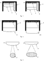
- FIG. 3 shows two different configurations of a lens module 3 according to the invention for adapting the detection range 6 of the radar sensor.
- the shape of the lens module shown has a circular detection area 6
- the in Figure 3b shown shape of the lens module has an oval detection area 6 .
- the lens modules cover in Figures 3a and 3b different detection areas. They are therefore connected to the radar detector unit 2 in an interchangeable manner, for example by means of a screw connection, bayonet, plugging, etc.
- the configurations of a radar sensor 1 shown illustrate the different options for connecting a lens module 3 to a receiving device for the lens module 4 , the connection option permitting the lens module ( 3 ) to be replaced by a plug-in connection 7a ( Figure 4a ), a screw connection or bayonet connection 7b ( Figure 4b ) or an interlocking tether 7c ( Figure 4c ) permitted.
- the configurations shown here are shown for two different geometries of the lens module 3a and 3b .
- FIG 5 shows an example of a radar module 8 according to the invention, consisting of two radar sensors 1 with associated detection areas 6, which are connected to one another via a control unit for radar sensors 9 .
- the lighting system 10 shown has a radar sensor 1 (for example with an oval detection area) which sends a movement detection signal to a control unit for lighting systems 11 wirelessly or by wire (for example via a bus such as a DALI bus).
- This signal is processed and used by the control unit for lighting systems 11 , for example (here: three) to control lights 12 and for example to switch the three lights 12 on/off or to regulate their brightness.
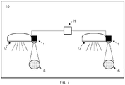
- the lighting system 10 shown has two radar sensors 1 (e.g. with a round detection area), which are each integrated into the housing of a light 12 and control this light, for example in order to switch the light on/off or to regulate its brightness, and in doing so wirelessly or wired (e.g via a bus such as a DALI bus) via a control unit for lighting systems 11 are connected to one another.
- radar sensors 1 e.g. with a round detection area
Landscapes
- Engineering & Computer Science (AREA)
- Radar, Positioning & Navigation (AREA)
- Remote Sensing (AREA)
- Physics & Mathematics (AREA)
- Computer Networks & Wireless Communication (AREA)
- General Physics & Mathematics (AREA)
- Electromagnetism (AREA)
- General Engineering & Computer Science (AREA)
- Circuit Arrangement For Electric Light Sources In General (AREA)
- Arrangement Of Elements, Cooling, Sealing, Or The Like Of Lighting Devices (AREA)
- Radar Systems Or Details Thereof (AREA)
Abstract
Description
- Die Erfindung betrifft einen Radarsensor für eine Beleuchtungsanlage gemäß dem Oberbegriff des Anspruchs 1.
- Radarsensoren können zur Ansteuerung von Beleuchtungsanalgen genutzt werden, wobei die Radarsensoren Objekte, wie zum Beispiel Personen, erfassen und anhand des Signals des Radarsensors die Funktion der Beleuchtungsanlage steuern können. So kann ein Radarsensor oder ein Radarmodul bestehend aus mehreren Radarsensoren Signale an die Steuerungseinheit der Beleuchtungsanlage abgeben und so die Leuchten der Beleuchtungsanlage bei An-/Abwesenheit eines Objekts ein-/ausschalten, dimmen etc.
- Gemäß dem Stand der Technik weisen Beleuchtungsanlagen bereits Radarsensoren auf. Allerdings ist der Erfassungsbereich dieser Radarsensoren fest eingestellt und kann nur durch eine Veränderung der Sensitivität auf den Anwendungsbereich angepasst werden, was die Möglichkeiten zur Nutzung von Radarsensoren zur Ansteuerung von Beleuchtungsanalgen limitiert.
- Es ist die Aufgabe der vorliegenden Erfindung, einen flexibel anwendbaren Radarsensor und ein Radarmodul für eine Beleuchtungsanlage bereitzustellen.
- Diese Aufgabe wird mittels der Merkmalen der unabhängigen Ansprüche gelöst. Die Erfindung wird durch die Merkmale der abhängigen Patentansprüche weitergebildet.
- Der Radarsensor enthält bevorzugt eine Radardetektoreinheit und ist bevorzugt mit einem Linsenmodul für Radarstrahlen versehen ist, welches ausgewechselt werden kann, um den Erfassungsbereich des Radarsensors anzupassen.
- Unter einer Radardetektoreinheit wird hierbei eine Detektoreinheit verstanden, welches in der Lage ist, Radarstrahlung zu detektieren und ein Signal abhängig von der Intensität der detektierten Radarstrahlung zu erzeugen.
- Unter einem Linsenmodul für Radarstrahlen wird hierbei ein Linsenmodul verstanden, welches in der Lage ist, Radarstrahlung zu brechen und, abhängig von der Form des Linsenmoduls, Radarstrahlung unterschiedlich zu fokussieren.
- Das Linsenmodul ist bevorzugt so geformt, dass es eine kreisförmige Kontur des Erfassungsbereichs des Radarsensors bereitstellt.
- Das Linsenmodul ist weiterhin bevorzugt so geformt, dass es eine ovale Kontur des Erfassungsbereichs des Radarsensors bereitstellt, wobei die ovale Kontur bevorzugt hochkant im Raum angeordnet ist. Eine hochkant im Raum angeordnete Kontur ist insbesondere für die Anwendung in Korridoren, wie zum Beispiel in Korridoren zwischen Hochregallagern, geeignet und kann in solch einem speziellen Anwendungsfall eine effizientere Erfassung eines Objekts ermöglichen, als es eine kreisförmige Kontur erlaubt.
- Das Linsenmodul erlaubt vorzugsweise durch unterschiedliche Ausformung eine Anpassung des Abstands zwischen Radardetektoreinheit und Linsenmodul. Eine unterschiedliche Dicke des Linsenmoduls erlaubt beispielsweise eine Anpassung des effektiven Abstands zwischen der Brechungsebene des Linsenmoduls und der Radardetektoreinheit und so die Anpassung der Detektionsfläche an den jeweiligen Einsatzbereich und/oder Standort des Radarsensors.
- Die Aufnahmevorrichtung des Linsenmoduls erlaubt bevorzugter Weise ein Auswechseln des Linsenmoduls durch eine Steckverbindung, eine Schraubverbindung oder eine ineinandergreifende Halteverbindung.
- Unter dem Auswechseln des Linsenmoduls wird hierbei ein reversibler und zerstörungsfreier Austausch des Linsenmoduls verstanden.
- Für einen Radarsensor werden somit mehrere unterschiedliche Linsenmodule bereitgestellt, welche entfernbar befestigt sind. Ein einfaches Auswechseln des Linsenmoduls ermöglicht somit eine schnelle und simple Anpassung des gewünschten Erfassungsbereichs des Radarsensors an den jeweiligen Einsatzbereich und/oder Standort.
- Die Aufnahmevorrichtung des Linsenmoduls verfügt weiterhin bevorzugt über eine Einstellvorrichtung, welche eine Anpassung des Abstands, beispielsweise durch Drehung eines Gewindes, zwischen Radardetektoreinheit und Linsenmodul ermöglicht. Eine Anpassung des Abstands zwischen Radardetektoreinheit und Linsenmodul ermöglicht eine Veränderung der erfassten Detektionsfläche des Radarsensors, und erlaubt so die Anpassung der Detektionsfläche an den jeweiligen Einsatzbereich und/oder Standort des Radarsensors.
- Die Erfindung umfasst weiterhin ein Radarmodul für eine Beleuchtungsanlage, wobei abhängig von dem Signal des Radarmoduls die Helligkeit der Beleuchtungsanlage gesteuert werden kann, welches dadurch gekennzeichnet ist, dass das Radarmodul wenigstens zwei Radarsensoren enthält, welche optional über eine Steuerungseinheit für Radarsensoren miteinander verbunden sind.
- Unter einer Steuerungseinheit für Radarsensoren wird hierbei ein elektrisches oder elektronisches, bevorzugt ein elektronisches, Bauteil verstanden, welches die Signale von wenigstens zwei Radarsensoren verarbeiten und daraus ein einziges, gemeinsames Signal erzeugen kann, um die Helligkeit der Beleuchtungsanlage zu steuern.
- Das Radarmodul enthält bevorzugt wenigstens zwei Radarsensoren, welche sich hinsichtlich der Kontur des Erfassungsbereichs unterscheiden. Die Kombination von wenigstens zwei Radarsensoren mit unterschiedlichen Erfassungsbereichen erlaubt eine weitreichende Anpassung der Detektionsfläche des Radarmoduls an den jeweiligen Einsatzbereich und/oder Standort.
- Die Erfindung umfasst weiterhin eine Beleuchtungsanlage. Gemäß der Erfindung umfasst die Beleuchtungsanlage wenigstens eine Leuchte, bevorzugt zwei oder mehr Leuchten, sowie einen Radarsensor oder ein Radarmodul. Die wenigstens eine Leuchte ist optional mit einer Steuerungseinheit für Beleuchtungsanlagen verbunden, welche mit einem Radarsensor oder einem Radarmodul in Kommunikation steht.
- Eine Veränderung des Signals des Radarsensors oder des Radarmoduls kann dadurch hervorgerufen werden, dass sich ein Objekt, beispielsweise eine Person oder ein Fahrzeug, in den Erfassungsbereich bewegt. Eine Veränderung eines solchen Bewegungs-Erfassungssignals kann von der Steuerungseinheit für Beleuchtungsanlagengenutzt werden, um die wenigstens eine Leuchte der Beleuchtungsanlage bei An-/Abwesenheit eines Objekts ein-/ausschalten oder die Helligkeit der wenigstens eine Leuchte zu regulieren.
- Die wenigstens eine Leuchte der Beleuchtungsanlage kann dabei drahtlos oder drahtgebunden (beispielsweise über einen Bus wie bspw. einen DALI-Bus), vorzugsweise drahtlos, mit dem Radarsensor oder Radarmodul in Kommunikation stehen.
- Ist die wenigstens eine Leuchte mit einer Steuerungseinheit für Beleuchtungsanlagen verbunden, steht die Steuerungseinheit für Beleuchtungsanlagen dabei drahtlos oder drahtgebunden (beispielsweise über einen Bus wie bspw. einen DALI-Bus), vorzugsweise drahtlos, mit dem Radarsensor oder Radarmodul in Kommunikation.
- In einer bevorzugten Ausführungsform kann ein erfindungsgemäßer Radarsensor oder ein erfindungsgemäßes Radarmodul auch in das Gehäuse einer Leuchte integriert sein und mit einer Steuereinrichtung der Leuchte zu kommunizieren, um die Leuchte beispielsweise ein-/auszuschalten oder deren Helligkeit zu regulieren.
- In einer bevorzugten Ausführungsform einer Beleuchtungsanlage können mehrere Leuchten, welche jeweils über einen integrierten Radarsensor oder ein integriertes Radarmodul verfügen, drahtlos oder drahtgebunden (beispielsweise über einen Bus wie bspw. einen DALI-Bus), optional über eine Steuerungseinheit für Beleuchtungsanlagen, miteinander verbunden sein, so dass sie ein System bilden.
- Nachfolgend soll die Erfindung anhand der beigefügten Zeichnungen näher erläutert werden. Es zeigen:
-
Fig. 1, Fig. 2 undFig. 4 zeigen Ausgestaltungen eines erfindungsmäßen Radarsensors 1. -
Fig. 3 zeigt Ausgestaltungen eines erfindungsgemäßen Linsenmoduls 3. -
Fig. 5 zeigt die Ausgestaltung eines erfindungsgemäßen Radarmoduls 8. -
Fig. 6 undFig. 7 zeigen Ausgestaltungen einer erfindungsgemäßen Beleuchtungsanlage 10. - Der in
Fig. 1 gezeigte Radarsensor 1 weist eine Radardetektoreinheit 2, ein Linsenmodul 3 sowie eine Aufnahmevorrichtung für das Linsenmodul 4 (als Beispiele für eine Radaroptik) auf. Weiterhin ist eine Einstellvorrichtung 5 vorhanden, welche eine Veränderung des Abstands zwischen der Radardetektoreinheit 2 und dem Linsenmodul 3 ermöglicht. Die Veränderung des Abstands zwischen der Radardetektoreinheit 2 und dem Linsenmodul 3 wird im Falle des abgebildeten Radarsensors derFig. 1 durch eine relative Drehung und mittels einer Gewindeverbindung realisiert.Fig. 1a zeigt einen geringeren Abstand, währendFig. 1b einen größeren Abstand zwischen der Radardetektoreinheit 2 und dem Linsenmodul 3 zeigt. -
Fig. 2 zeigt zwei unterschiedliche Ausgestaltungen erfindungsgemäßer Linsenmodule 3n und 3m zur Anpassung des effektiven Abstands zwischen der Brechungsebene des Linsenmoduls 3 und der Radardetektoreinheit 2. Diese Ausführungsform ermöglicht es, zwischen einem festen geringeren Abstand (Fig. 2a ) und einem festen weiteren Abstand (Fig. 2b ) zu wählen. Die Linsenmodule inFig. 2a und Fig. 2b decken unterschiedliche Erfassungsbereiche ab. Sie sind also austauschbar mit der Radardetektoreinheit 2 verbunden, beispielsweise Mittels Verschraubung, Bajonett, Aufstecken etc. -
Fig. 3 zeigt zwei unterschiedliche Ausgestaltungen eines erfindungsgemäßen Linsenmoduls 3 zur Anpassung des Erfassungsbereichs 6 des Radarsensors. Die inFig. 3a abgebildete Form des Linsenmoduls weist einen kreisförmigen Erfassungsbereich 6 auf, während die inFig. 3b abgebildete Form des Linsenmoduls einen ovalen Erfassungsbereich 6 aufweist. Wiederum decken die Linsenmodule inFig. 3a und Fig. 3b unterschiedliche Erfassungsbereiche ab. Sie sind also daher austauschbar mit der Radardetektoreinheit 2 verbunden, beispielsweise Mittels Verschraubung, Bajonett, Aufstecken etc. - Die in
Fig. 4 gezeigten Ausgestaltungen eines Radarsensors 1 verdeutlichen die unterschiedlichen Möglichkeiten, ein Linsenmodul 3 mit einer Aufnahmevorrichtung für das Linsenmodul 4 zu verbinden, wobei die Verbindungsmöglichkeit ein Auswechseln des Linsenmoduls (3) durch eine Steckverbindung 7a (Fig. 4a ), eine Schraubverbindung oder Bajonettverbindung 7b (Fig. 4b ) oder eine ineinandergreifende Halteverbindung 7c (Fig. 4c ) erlaubt. Die inFig. 4 gezeigten Ausgestaltungen sind hierbei für zwei unterschiedliche Geometrien des Linsenmoduls 3a und 3b gezeigt. -
Fig. 5 zeigt ein Beispiel für ein erfindungsgemäßes Radarmodul 8, bestehend aus zwei Radarsensoren 1 mit zugehörigen Erfassungsbereichen 6, welche über eine Steuerungseinheit für Radarsensoren 9 miteinander verbunden sind. - Die in
Fig. 6 gezeigte Beleuchtungsanlage 10 weist einen Radarsensor 1 (beispielsweise mit ovalem Erfassungsbereich) auf, welcher drahtlos oder drahtgebunden (beispielsweise über einen Bus wie bspw. einen DALI-Bus) ein Bewegungs-Erfassungssignal an eine Steuerungseinheit für Beleuchtungsanlagen 11 sendet. Dieses Signal wird von der Steuerungseinheit für Beleuchtungsanlagen 11 verarbeitet und genutzt, um beispielsweise (hier: drei) Leuchten 12 anzusteuern und beispielsweise die drei Leuchten 12 ein-/auszuschalten oder deren Helligkeit zu regulieren. - Die in
Fig. 7 gezeigte Beleuchtungsanlage 10 weist zwei Radarsensoren 1 (beispielsweise mit rundem Erfassungsbereich) auf, welche in je in das Gehäuse einer Leuchte 12 integriert sind und diese Leuchte ansteuern um die Leuchte beispielsweise ein-/auszuschalten oder deren Helligkeit zu regulieren und dabei drahtlos oder drahtgebunden (beispielsweise über einen Bus wie bspw. einen DALI-Bus) über eine Steuerungseinheit für Beleuchtungsanlagen 11 miteinander verbunden sind.
Claims (15)
- Radarsensor (1) für eine Beleuchtungsanlage (10), wobei der Radarsensor (1) einen bestimmten Erfassungsbereich (6) überwacht und abhängig von dem Signal des Radarsensors (1) die Helligkeit der Beleuchtungsanlage (10) gesteuert werden kann, gekennzeichnet dadurch, dass der Erfassungsbereich (6) durch Veränderung einer dem Radarsensor vorgesetzten Radaroptik, wie bspw. einem Linsenmodul, verstellbar ist.
- Radarsensor (1) für eine Beleuchtungsanlage (10) nach Anspruch 1, dadurch gekennzeichnet, dass die Form des Erfassungsbereichs (6) durch Veränderung der Radaroptik anpassbar ist.
- Radarsensor (1) für eine Beleuchtungsanlage (10) nach Anspruch 1 oder 2, dadurch gekennzeichnet, dass der Radarsensor (1) eine Radardetektoreinheit (2) enthält und ein Linsenmodul (3) als Radaroptik aufweist, welches ausgewechselt werden kann, um den Erfassungsbereich des Radarsensors (6) anzupassen.
- Radarsensor (1) für eine Beleuchtungsanlage (10) nach Anspruch 1 oder 3, dadurch gekennzeichnet, dass das Linsenmodul (3) eine kreisförmige Kontur des Erfassungsbereichs des Radarsensors (6) bereitstellt.
- Radarsensor (1) für eine Beleuchtungsanlage (10) nach einem der Ansprüche 1 bis 4, dadurch gekennzeichnet, dass das Linsenmodul (3) eine ovale Kontur des Erfassungsbereichs des Radarsensors (6) bereitstellt, wobei die ovale Kontur bevorzugt hochkant im Raum angeordnet ist.
- Radarsensor (1) für eine Beleuchtungsanlage (10) nach einem der Ansprüche 1 bis 5, dadurch gekennzeichnet, dass unterschiedlich ausgeformte Linsenmodule (3) eine Anpassung des Abstands zwischen Radardetektoreinheit (2) und Linsenmodul (3) ermöglichen.
- Radarsensor (1) für eine Beleuchtungsanlage (10) nach einem der Ansprüche 1 bis 6, dadurch gekennzeichnet, dass die Aufnahmevorrichtung des Linsenmoduls (4) ein Auswechseln des Linsenmoduls (3) durch eine Steckverbindung (7a), eine Schraubverbindung (7b) oder eine ineinandergreifende Halteverbindung (7c), vorzugsweise durch eine Schraubverbindung (7b), erlaubt.
- Radarsensor (1) für eine Beleuchtungsanlage (10) nach einem der Ansprüche 1 bis 7, dadurch gekennzeichnet, dass die Aufnahmevorrichtung des Linsenmoduls (4) über eine Einstellvorrichtung (5) verfügt, welche eine Anpassung des Abstands zwischen Radardetektoreinheit (2) und Linsenmodul (3) ermöglicht.
- Radarmodul (8) für eine Beleuchtungsanlage (10), wobei abhängig von dem Signal des Radarmoduls die Helligkeit der Beleuchtungsanlage gesteuert werden kann, dadurch gekennzeichnet, dass das Radarmodul (8) wenigstens zwei Radarsensoren (1) gemäß der Ansprüche 1 bis 7 enthält, welche optional über eine Steuerungseinheit für Radarsensoren (9) miteinander verbunden sind.
- Radarmodul (8) für eine Beleuchtungsanlage (10) nach Anspruch 9, dadurch gekennzeichnet, dass das Radarmodul (8) wenigstens zwei Radarsensoren (1) gemäß der Ansprüche 1 bis 7 enthält, welche sich hinsichtlich der Kontur des Erfassungsbereichs (6) unterscheiden.
- Beleuchtungsanlage (10), aufweisend wenigstens eine Leuchte (12), welche optional mit einer Steuerungseinheit für Beleuchtungsanlagen (11) verbunden sein kann, in Kommunikation stehend mit einem Radarsensor (1) gemäß der Ansprüche 1 bis 8 oder einem Radarmodul (8) gemäß der Ansprüche 9 oder 10.
- Beleuchtungsanlage (10) nach Anspruch 11, wobei die wenigstens eine Leuchte (12) drahtlos oder drahtgebunden, vorzugsweise drahtlos, mit dem Radarsensor (1) oder Radarmodul (8) in Kommunikation steht.
- Beleuchtungsanlage (10) nach Anspruch 11, wobei die Steuerungseinheit für Beleuchtungsanlagen (11) der wenigstens einen Leuchte (12) drahtlos oder drahtgebunden, vorzugsweise drahtlos, mit dem Radarsensor (1) oder Radarmodul (8) in Kommunikation steht.
- Beleuchtungsanlage (10), aufweisend wenigstens eine Leuchte (12), wobei ein Radarsensor (1) gemäß der Ansprüche 1 bis 8 oder ein Radarmodul (8) gemäß der Ansprüche 9 oder 10 in die wenigstens eine Leuchte integriert ist und diese Leuchte ansteuern kann, beispielsweise um die Leuchte ein-/auszuschalten oder deren Helligkeit zu regulieren.
- Beleuchtungsanlage (10) nach Anspruch 14, wobei die Beleuchtungsanlage (10) wenigstens zwei Leuchten mit integriertem Radarsensor (1) oder Radarmodul (8) enthält, welche optional über eine Steuerungseinheit für Beleuchtungsanlagen (11), drahtlos oder drahtgebunden, vorzugsweise drahtlos, miteinander in Kommunikation stehen.
Applications Claiming Priority (1)
| Application Number | Priority Date | Filing Date | Title |
|---|---|---|---|
| DE102021110183.2A DE102021110183A1 (de) | 2021-04-22 | 2021-04-22 | Radarsensor für beleuchtungsanlagen |
Publications (2)
| Publication Number | Publication Date |
|---|---|
| EP4080236A1 true EP4080236A1 (de) | 2022-10-26 |
| EP4080236B1 EP4080236B1 (de) | 2026-04-29 |
Family
ID=80930153
Family Applications (1)
| Application Number | Title | Priority Date | Filing Date |
|---|---|---|---|
| EP22163406.6A Active EP4080236B1 (de) | 2021-04-22 | 2022-03-22 | Radarmodul für beleuchtungsanlagen |
Country Status (3)
| Country | Link |
|---|---|
| EP (1) | EP4080236B1 (de) |
| AT (1) | AT18034U1 (de) |
| DE (1) | DE102021110183A1 (de) |
Citations (4)
| Publication number | Priority date | Publication date | Assignee | Title |
|---|---|---|---|---|
| US5926127A (en) * | 1996-10-17 | 1999-07-20 | Robert Bosch Gmbh | Motor vehicle radar system |
| DE20302167U1 (de) * | 2003-02-05 | 2004-06-17 | Semmler, Franz | Bewegungsmelder |
| US20090237509A1 (en) * | 2008-03-21 | 2009-09-24 | Vibrashine, Inc. | Motion activated camera system |
| DE102019122612A1 (de) * | 2019-08-22 | 2021-02-25 | Selux Ag | Radarbewegungsmelder |
Family Cites Families (2)
| Publication number | Priority date | Publication date | Assignee | Title |
|---|---|---|---|---|
| JP2008146933A (ja) * | 2006-12-07 | 2008-06-26 | Koito Mfg Co Ltd | 車両用灯具 |
| US7902508B2 (en) | 2008-07-21 | 2011-03-08 | The Watt Stopper Inc | Selectable field motion detector |
-
2021
- 2021-04-22 DE DE102021110183.2A patent/DE102021110183A1/de active Pending
- 2021-08-03 AT ATGM50149/2021U patent/AT18034U1/de not_active IP Right Cessation
-
2022
- 2022-03-22 EP EP22163406.6A patent/EP4080236B1/de active Active
Patent Citations (4)
| Publication number | Priority date | Publication date | Assignee | Title |
|---|---|---|---|---|
| US5926127A (en) * | 1996-10-17 | 1999-07-20 | Robert Bosch Gmbh | Motor vehicle radar system |
| DE20302167U1 (de) * | 2003-02-05 | 2004-06-17 | Semmler, Franz | Bewegungsmelder |
| US20090237509A1 (en) * | 2008-03-21 | 2009-09-24 | Vibrashine, Inc. | Motion activated camera system |
| DE102019122612A1 (de) * | 2019-08-22 | 2021-02-25 | Selux Ag | Radarbewegungsmelder |
Also Published As
| Publication number | Publication date |
|---|---|
| DE102021110183A1 (de) | 2022-10-27 |
| AT18034U1 (de) | 2023-11-15 |
| EP4080236B1 (de) | 2026-04-29 |
Similar Documents
| Publication | Publication Date | Title |
|---|---|---|
| DE2816302C2 (de) | Anzeigevorrichtung für Meßwerte | |
| EP2136128B1 (de) | Operationsleuchte | |
| EP2043117A2 (de) | Schnellspanneinrichtung | |
| DE102012110167B4 (de) | Sensor | |
| EP3456151A1 (de) | Beleuchtungsvorrichtung mit konsistenten lichteigenschaften | |
| EP3889981A1 (de) | Steuerungssystem für elektrisch gesteuerte anlagen | |
| EP4080236B1 (de) | Radarmodul für beleuchtungsanlagen | |
| EP3092970A1 (de) | Verfahren und vorrichtung zur ansteuerung einer operationsleuchte | |
| DE10337379A1 (de) | Vorrichtung zur UV-Behandlung von strömenden Fluiden | |
| EP4418056B1 (de) | Bedieneinheit und verfahren zum bedienen einer anlage mit einer bedieneinheit | |
| DE2811413A1 (de) | Naeherungsschalter | |
| DE19926946A1 (de) | Vorrichtung zur pneumatischen Positionskontrolle | |
| EP3185651A1 (de) | Verfahren zur beleuchtungsregelung und system | |
| DE202015105610U1 (de) | Sensor zur Bewegungserfassung | |
| AT526331B1 (de) | Leuchte zum Ausleuchten wenigstens zweier Raumbereiche mit einem auf einen ersten Raumbereich ausgerichteten ersten Leuchtsegment | |
| EP4169355B1 (de) | System zur erkennung einer orientierung eines lichtsensors | |
| DE10023167B4 (de) | Passiv-Infrarot-Bewegungsmelder | |
| DE102004008038B4 (de) | Elektrodenzustandsmeßeinrichtung | |
| EP0231004B1 (de) | Verfahren zur Selbstkontrolle einer optoelektronischen Risserkennungseinrichtung, insbesondere nach dem Magnetpulververfahren | |
| EP1533998A2 (de) | Kamerasystem | |
| DE10358993B4 (de) | Lichtsignalgeber und Lichtsignalanlage mit einem Lichtsignalgeber | |
| DE29717042U1 (de) | Einheit zum Erfassen von Signalen | |
| DE20017210U1 (de) | Vorrichtung zum Bestimmen des Verschmutzungsgrades von Filtern | |
| EP3062112B1 (de) | Vorrichtung zur erkennung der präsenz oder bewegung von personen | |
| EP3062111A1 (de) | Vorrichtung zur erkennung der präsenz oder bewegung von personen |
Legal Events
| Date | Code | Title | Description |
|---|---|---|---|
| PUAI | Public reference made under article 153(3) epc to a published international application that has entered the european phase |
Free format text: ORIGINAL CODE: 0009012 |
|
| STAA | Information on the status of an ep patent application or granted ep patent |
Free format text: STATUS: THE APPLICATION HAS BEEN PUBLISHED |
|
| AK | Designated contracting states |
Kind code of ref document: A1 Designated state(s): AL AT BE BG CH CY CZ DE DK EE ES FI FR GB GR HR HU IE IS IT LI LT LU LV MC MK MT NL NO PL PT RO RS SE SI SK SM TR |
|
| STAA | Information on the status of an ep patent application or granted ep patent |
Free format text: STATUS: REQUEST FOR EXAMINATION WAS MADE |
|
| 17P | Request for examination filed |
Effective date: 20230328 |
|
| RBV | Designated contracting states (corrected) |
Designated state(s): AL AT BE BG CH CY CZ DE DK EE ES FI FR GB GR HR HU IE IS IT LI LT LU LV MC MK MT NL NO PL PT RO RS SE SI SK SM TR |
|
| REG | Reference to a national code |
Ref country code: DE Ref legal event code: R079 Free format text: PREVIOUS MAIN CLASS: G01S0007020000 Ipc: H01Q0001220000 Ref country code: DE Ref legal event code: R079 Ref document number: 502022007767 Country of ref document: DE Free format text: PREVIOUS MAIN CLASS: G01S0007020000 Ipc: H01Q0001220000 |
|
| GRAP | Despatch of communication of intention to grant a patent |
Free format text: ORIGINAL CODE: EPIDOSNIGR1 |
|
| STAA | Information on the status of an ep patent application or granted ep patent |
Free format text: STATUS: GRANT OF PATENT IS INTENDED |
|
| RIC1 | Information provided on ipc code assigned before grant |
Ipc: H01Q 1/22 20060101AFI20251219BHEP Ipc: G01S 7/02 20060101ALI20251219BHEP Ipc: G01S 13/04 20060101ALI20251219BHEP Ipc: G01S 13/86 20060101ALI20251219BHEP Ipc: G01S 13/87 20060101ALI20251219BHEP Ipc: G01S 13/88 20060101ALI20251219BHEP Ipc: H01Q 19/06 20060101ALI20251219BHEP Ipc: H01Q 3/01 20060101ALI20251219BHEP Ipc: H01Q 3/14 20060101ALI20251219BHEP Ipc: H01Q 25/00 20060101ALI20251219BHEP |
|
| GRAS | Grant fee paid |
Free format text: ORIGINAL CODE: EPIDOSNIGR3 |
|
| INTG | Intention to grant announced |
Effective date: 20260120 |
|
| P01 | Opt-out of the competence of the unified patent court (upc) registered |
Free format text: CASE NUMBER: UPC_APP_0005595_4080236/2026 Effective date: 20260216 |
|
| GRAA | (expected) grant |
Free format text: ORIGINAL CODE: 0009210 |
|
| STAA | Information on the status of an ep patent application or granted ep patent |
Free format text: STATUS: THE PATENT HAS BEEN GRANTED |
|
| AK | Designated contracting states |
Kind code of ref document: B1 Designated state(s): AL AT BE BG CH CY CZ DE DK EE ES FI FR GB GR HR HU IE IS IT LI LT LU LV MC MK MT NL NO PL PT RO RS SE SI SK SM TR |
|
| REG | Reference to a national code |
Ref country code: CH Ref legal event code: F10 Free format text: ST27 STATUS EVENT CODE: U-0-0-F10-F00 (AS PROVIDED BY THE NATIONAL OFFICE) Effective date: 20260429 Ref country code: GB Ref legal event code: FG4D Free format text: NOT ENGLISH |
|
| REG | Reference to a national code |
Ref country code: DE Ref legal event code: R096 Ref document number: 502022007767 Country of ref document: DE |