EP4079627B1 - Einspritzbare rippenfussklemme - Google Patents
Einspritzbare rippenfussklemme Download PDFInfo
- Publication number
- EP4079627B1 EP4079627B1 EP22155795.2A EP22155795A EP4079627B1 EP 4079627 B1 EP4079627 B1 EP 4079627B1 EP 22155795 A EP22155795 A EP 22155795A EP 4079627 B1 EP4079627 B1 EP 4079627B1
- Authority
- EP
- European Patent Office
- Prior art keywords
- rib
- cleat
- channel
- stringer
- sealant
- Prior art date
- Legal status (The legal status is an assumption and is not a legal conclusion. Google has not performed a legal analysis and makes no representation as to the accuracy of the status listed.)
- Active
Links
Images


Classifications
-
- B—PERFORMING OPERATIONS; TRANSPORTING
- B64—AIRCRAFT; AVIATION; COSMONAUTICS
- B64C—AEROPLANES; HELICOPTERS
- B64C3/00—Wings
- B64C3/18—Spars; Ribs; Stringers
-
- B—PERFORMING OPERATIONS; TRANSPORTING
- B64—AIRCRAFT; AVIATION; COSMONAUTICS
- B64C—AEROPLANES; HELICOPTERS
- B64C3/00—Wings
- B64C3/18—Spars; Ribs; Stringers
- B64C3/182—Stringers, longerons
-
- B—PERFORMING OPERATIONS; TRANSPORTING
- B64—AIRCRAFT; AVIATION; COSMONAUTICS
- B64C—AEROPLANES; HELICOPTERS
- B64C3/00—Wings
- B64C3/18—Spars; Ribs; Stringers
- B64C3/187—Ribs
-
- B—PERFORMING OPERATIONS; TRANSPORTING
- B64—AIRCRAFT; AVIATION; COSMONAUTICS
- B64C—AEROPLANES; HELICOPTERS
- B64C3/00—Wings
- B64C3/24—Moulded or cast structures
-
- B—PERFORMING OPERATIONS; TRANSPORTING
- B64—AIRCRAFT; AVIATION; COSMONAUTICS
- B64C—AEROPLANES; HELICOPTERS
- B64C3/00—Wings
- B64C3/34—Tanks constructed integrally with wings, e.g. for fuel or water
-
- B—PERFORMING OPERATIONS; TRANSPORTING
- B64—AIRCRAFT; AVIATION; COSMONAUTICS
- B64F—GROUND OR AIRCRAFT-CARRIER-DECK INSTALLATIONS SPECIALLY ADAPTED FOR USE IN CONNECTION WITH AIRCRAFT; DESIGNING, MANUFACTURING, ASSEMBLING, CLEANING, MAINTAINING OR REPAIRING AIRCRAFT, NOT OTHERWISE PROVIDED FOR; HANDLING, TRANSPORTING, TESTING OR INSPECTING AIRCRAFT COMPONENTS, NOT OTHERWISE PROVIDED FOR
- B64F5/00—Designing, manufacturing, assembling, cleaning, maintaining or repairing aircraft, not otherwise provided for; Handling, transporting, testing or inspecting aircraft components, not otherwise provided for
- B64F5/10—Manufacturing or assembling aircraft, e.g. jigs therefor
-
- F—MECHANICAL ENGINEERING; LIGHTING; HEATING; WEAPONS; BLASTING
- F16—ENGINEERING ELEMENTS AND UNITS; GENERAL MEASURES FOR PRODUCING AND MAINTAINING EFFECTIVE FUNCTIONING OF MACHINES OR INSTALLATIONS; THERMAL INSULATION IN GENERAL
- F16B—DEVICES FOR FASTENING OR SECURING CONSTRUCTIONAL ELEMENTS OR MACHINE PARTS TOGETHER, e.g. NAILS, BOLTS, CIRCLIPS, CLAMPS, CLIPS OR WEDGES; JOINTS OR JOINTING
- F16B11/00—Connecting constructional elements or machine parts by sticking or pressing them together, e.g. cold pressure welding
- F16B11/006—Connecting constructional elements or machine parts by sticking or pressing them together, e.g. cold pressure welding by gluing
-
- F—MECHANICAL ENGINEERING; LIGHTING; HEATING; WEAPONS; BLASTING
- F16—ENGINEERING ELEMENTS AND UNITS; GENERAL MEASURES FOR PRODUCING AND MAINTAINING EFFECTIVE FUNCTIONING OF MACHINES OR INSTALLATIONS; THERMAL INSULATION IN GENERAL
- F16J—PISTONS; CYLINDERS; SEALINGS
- F16J15/00—Sealings
- F16J15/02—Sealings between relatively-stationary surfaces
- F16J15/06—Sealings between relatively-stationary surfaces with solid packing compressed between sealing surfaces
- F16J15/062—Sealings between relatively-stationary surfaces with solid packing compressed between sealing surfaces characterised by the geometry of the seat
Definitions
- the present invention relates to a rib foot cleat for sealing around a stringer passing through a rib mousehole in an aircraft assembly, an aircraft assembly with the rib foot cleat, a method for sealing a mousehole, a tool for forming a lip on a rib foot cleat, and a method for forming a lip on a rib foot cleat.
- Aircraft wings extend spanwise from a root end nearest the fuselage to a tip end.
- the wing has an upper wing cover having an upper aerodynamic surface, a lower wing cover having a lower aerodynamic surface, a leading edge and a trailing edge.
- Internally the wing is typically configured to provide a fuel carrying volume.
- a plurality of ribs extend generally chordwise between a front spar and a rear spar, the front and rear spars extending generally spanwise.
- the ribs are coupled to the spars and the covers to create a 'wing box' structure which is the main load bearing structure of the wing.
- the ribs may also be used to segment the fuel carrying volume of the wing into different bays.
- Stringers extend generally spanwise along the length of the wing on the interior side of the upper and lower wing covers and pass through 'mouseholes' in the ribs or rib feet. Fuel may freely move through the mouseholes in the rib into the neighbouring bay, or the mousehole may be sealed to prevent the flow of fuel. In order to accommodate potential geometrical variations of the aircraft component shapes or dimensions the mouseholes are necessarily fairly large.
- a 'dry bay' may be located within the wing directly above the engine/pylon for an aircraft with under-wing mounted engines.
- the dry bay does not contain any fuel and is a safety mechanism in case of engine failure, e.g. a rotor disk burst.
- the dry bay shares at least one rib with an adjacent fuel bay. Therefore, a number of mouseholes need to be sealed to prevent fuel leaking into the dry bay and keep the dry bay 'dry'.
- Sealing the dry bay presents a number of challenges, as it has a large number of complex joints to the rest of the wing. Due to the difficulty of gaining access to the area within the assembled wing, reliable sealing of the dry bay mouseholes is particularly difficult. Furthermore, the gaps between the mouseholes and the stringers is very large, the shape of the stringer is not simple and dry bay rib mouseholes are obliquely angled with the dry bay rib, which provide further sealing challenges. Accordingly, providing a repeatable and effective solution to reliably seal each the dry bay rib mousehole can be difficult to achieve.
- the elongated structure has a channel.
- the elongated structure is configured to be associated with a primary structure on a first side of the primary structure.
- US 10 279 922 B2 describes baffle fuel dams and tank boundary fuel dams having a single-piece or two-piece construction.
- EP 3702266A1 describes a sealing tool for sealing a stringer-receiving opening in an aircraft rib.
- the sealing tool includes a seal member arranged to seal a gap formed by the opening between the stringer and the rib.
- GB2579216 , US10279922 disclose rib foot cleats and sealing methods.
- a rib foot cleat for sealing around a stringer passing through a rib mousehole in an aircraft assembly, according to claim 1.
- a cleat is a component fastened to support and hold something in position.
- a rib is a chordwise extending structural component of an aircraft wing.
- a rib mousehole is a hole in an edge of a rib.
- a stringer is a longitudinal reinforcing member.
- the rib foot cleat is positioned over a stringer and is attached to the rib where the stringer passes through the rib mousehole, and is used to support and hold the sealant in place to seal around the stringer.
- the channel lip may optimise the amount of sealant required to fully seal the joint.
- the channel lip may guide any excess sealant that may otherwise protrude from the first and/or second channel opening rim and be guided towards the stringer.
- the channel lip may be made of sealant.
- the channel lip may be made of a curable material.
- the channel lip may be of the same material as the injected sealant to create a seal.
- the injected sealant may be curable to the channel lip.
- the channel lip may be made of silicone, polyurethane, polysulphide or silane-modified polymer.
- the channel lip may be made of closed cell foam.
- the rib foot cleat may comprise a first attachment flange for attaching the cleat body to the rib, and/or a second attachment flange for attaching the cleat body to a foot of the stringer.
- a further aspect of the invention provides an aircraft assembly, comprising a stringer reinforced cover and a rib having a mousehole with the stringer passing through the mousehole in the rib, and a rib foot cleat according to the first aspect arranged over the stringer at the rib mousehole and with cured sealant material inside the rib foot cleat which seals around the stringer passing through the rib mousehole.
- the rib may have a plurality of mouseholes each having a respective stringer passing through, and a respective rib foot cleat with cured sealant material which seals around the respective stringer passing through the respective rib mousehole.
- the rib may form a fuel tank boundary and the rib foot cleat and sealant may form a fluid-tight seal.
- the injected sealant may fully seal one side of the rib from the other.
- the rib may form a boundary between a fuel tank and a dry bay, or between a fuel tank and another fuel tank.
- a method a method of sealing around a stringer passing through a rib mousehole in an aircraft assembly, by providing a rib and a stringer extending through a mousehole of the rib, arranging a rib foot cleat according to the first aspect over the stringer, attaching the rib foot cleat to the rib; injecting sealant through the injection hole in the rib foot cleat to fill a gap between the cleat channel and the stringer with sealant so as to seal the gap.
- Holes may be drilled through the rib foot cleat and the rib after arranging the rib foot cleat over the stringer and before attaching the rib foot cleat to the rib.
- the lip(s) may be formed after drilling off the holes in the rib foot cleat and before the rib foot cleat is attached to the rib.
- Drilling the holes in the rib foot cleat enables the rib foot cleat to be correctly positioned over the stringer before the sealant is injected. This provides a more effective seal as the rib foot cleat may be positioned centrally over the stringer, accommodating tolerances in the assembly.
- the sealant may be injected in the injection hole by means of pneumatic assistance, preferably by a sealant gun.
- This provides a fast and repeatable method of introducing the sealant into the rib foot cleat, reducing the time of manufacture and assembly.
- the flow of injected sealant may be stopped when sealant escapes from the cleat channel.
- a tool for forming a lip on a rib foot cleat having a cleat body defining a cleat channel configured to be arranged over a stringer, and an attachment flange for attaching the cleat body to a rib, wherein the cleat channel is generally U-shaped and terminates at a first channel opening rim on one side of the cleat body and at a second channel opening rim on an opposite side of the cleat body, the tool comprising: a tool body configured to be placed against the cleat channel of the rib foot cleat, the tool body having at least one recess which extends at least partially around an interior of the cleat channel adjacent the first and/or second channel opening rim; and a locating feature for aligning the tool body against the cleat body of the rib foot cleat.
- the tool body may comprise two respective recesses that extend around an interior of the cleat channel adjacent the respective first and second channel opening rim.
- the tool may be collapsible.
- the tool body may be flexible to enable the collapsing of the tool.
- the tool body may be more rigid and incorporate a hinge between tool body portions.
- the tool body may have at least one handle for manually collapsing the collapsible tool.
- the tool may be made of nylon so that sealant does not adhere to the tool.
- a method of forming a lip on a rib foot cleat having a cleat body defining a cleat channel configured to be arranged over a stringer, and an attachment flange for attaching the cleat body to a rib, wherein the cleat channel is generally U-shaped and terminates at a first channel opening rim on one side of the cleat body and at a second channel opening rim on an opposite side of the cleat body, the method comprising providing the tool, inserting the tool in the rib foot cleat such that the tool body is be placed against the cleat channel of the rib foot cleat; injecting sealant in the at least one recess of the tool body; curing the sealant and removing the tool.
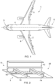
- FIG. 1 shows an aircraft 1 with starboard wing 2, port wing 3, fuselage 4, a nose end 5 and a tail end 6.
- the aircraft 1 is a typical jet passenger transonic transport aircraft but the invention is applicable to a wide variety of fixed wing aircraft types, including commercial, military, passenger, cargo, jet, propeller, general aviation etc.
- Each wing 2,3 has an upper and lower wing covers 18, which are strengthened and stiffened by a plurality of stringers 14 which extend generally spanwise along the wing from the wing root near the fuselage to the wing tip. Internally the wing is configured to provide a fuel carrying volume.
- a plurality of ribs 12 extend generally chordwise between a front spar and a rear spar (not shown), the front and rear spars extending generally spanwise.
- the ribs are coupled to the spars and the covers to create a 'wing box' structure which is the main load bearing structure of the wing.
- the ribs also segment the fuel carrying volume of the wing into different bays.
- a 'dry bay' 8 is located adjacent and above an under-wing mounted main engine on the wing 2.
- the dry bay does not contain fuel so that in the event of engine malfunction or failure, where components of the engine may directly impact the wing, no leak of fuel occurs.
- the dry bay is adjacent to at least one fuel tank bay in the wing.
- the port wing 3 is constructed similarly.
- Figure 2 shows a portion of an aircraft wing assembly 20 of the wing 2, in particular the rib 12, stringers 14, lower wing cover 18 and rib mouseholes 16 through which the respective stringers 14 pass.
- the rib 12 forms a boundary between a fuel tank bay 11 and the dry bay 8.
- Rib 12 extends generally perpendicular, vertically away from lower cover 18 and is connected to the lower cover at a lower end by rib feet and is connected to the upper cover at an upper end by rib feet (not shown).
- Rib 12 has a plurality of mouseholes 16 at the lower edge and a plurality of mouseholes at the upper edge (not shown). The rib mouseholes are formed in the rib to enable each of the stringers to pass though the rib without causing the requirement to fabricate any joints in the stringers.
- Stringers 14 extend continuously through the respective rib mouseholes 16 of the rib 12.
- the stringer profile in Figure 2 is shown to be a 'Z' stringer, however, it will be understood that any number of stringer profiles may be used, such as omega, top-hat, C-shaped; or any other suitable design.
- the mouseholes are sized to closely match the profile of the stringer to minimise the gap between the stringer and the rib, whilst allowing a clearance.
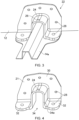
- Figure 3 shows the detail of an aircraft assembly 22 in which a rib foot cleat 21 is arranged over stringer 14a.
- the stringer 14a has a top hat profile different than the Z-shaped stringer 14 but any suitable stringer profile may be used.
- the rib foot cleat may be made of any suitable material, such as metal or a composite material.
- the rib foot cleat may be additively manufactured.
- Figure 4 shows the rib foot cleat 21 alone for clarity.
- the rib foot cleat 21 has a body 24 defining a cleat channel 34 configured to be arranged over the stringer 14a.
- the cleat body may have a bell-shaped, arched or roof portion extending over the cleat channel 34.
- the rib foot cleat 21 is arranged on one side of the rib 12, and is preferably on the inside of the dry bay 8. However, two rib foot cleats 21 may be placed one on either side of one mousehole 16.
- the rib foot cleat body 24 has a first attachment flange 30 for attaching the cleat body to the rib 12.
- a second attachment flange 32 extends perpendicular to the first attachment flange 30.
- the second attachment flange is configured for attaching the cleat body to a foot of the stringer 14a and the wing cover 18.
- the rib foot cleat body may be a unitary structure comprising the first and second attachment flanges 30, 32 and the arched portion defining the cleat channel 34.
- the second attachment flange 32 may be formed in two portions, one on either side of the cleat channel 34.
- Each attachment flange 30, 32 has a number of fastener holes 28, used to secure the rib foot cleat 21 to the rib 12 and stringer 14a/cover 18 respectively.
- the rib foot cleat channel 34 is U-shaped and terminates at a first channel opening rim 34a at one side of the cleat body 24 and a second channel opening rim 34b (shown in figure 6 ) at the opposite side of the cleat body 24.
- the injection hole 26 may be formed in apex of the arched portion of the rib foot cleat body 24.
- the injection hole may be formed by drilling or through any suitable method.
- injection hole 26, or a plurality of injection holes may be positioned in any suitable area of the cleat body 24 so as to be placed in fluid communication with the cleat channel 34.
- injection hole 26 Preferably a single, apex located injection hole 26 is provided.
- the rib foot cleat channel 34 is shown in Figure 4 as being U-shaped and arranged over stringer 14a, which has a top-hat stringer profile. However, it will be understood that any suitable shape of stringer profile, such as C-shaped, Z-shaped; or any other suitable design may be used.
- the rib foot cleat channel 34 and rib foot body 30 may be sized and modified to closely match the profile of the stringer to minimise the gap between the stringer and rib foot cleat channel 34, whilst permitting the rib foot cleat channel 34 to be placed over the stringer and for attachment of the rib foot cleat body 30 to the rib and to the foot of the stringer.
- the rib foot cleat 21 further includes a channel lip 56 (shown in figure 7 ) that extends at least partially around the interior of the cleat channel 34 or adjacent to the first and/or second channel opening rim, 34a and 34b.
- the channel lip 56 is positioned in a way to act as a barrier between the channel body 34 and the external environment and preferably, to delimit the inserted sealant from exuding during the injection process.
- the channel lip 56 is preferably formed along the periphery of the channel rims 34a and 34b.
- channel lip designs may be employed to seal a gap between the cleat body 24 and the stringer.
- a single lip may be formed along the centre of the cleat body 24, such that when sealant is injected, only one half of the cleat channel 34 is filled.
- the channel lips may be formed partially down the peripheral edges 34a and 34b, or from a set distance from the peripheral edge into the cleat channel.
- two channel lips 56 are formed adjacent to the respective first and second channel opening rim 34a and 34b.
- the channel lips are preferably formed before the rib foot cleat 21 is attached to rib 12 and stringer 14a.
- the channel lips may be formed from sealant.
- the lips may be made of any curable sealant, such as silicone, polyurethane, polysulphide, or silane-modified polymer.
- the same material used for forming channel lips 56 is used to inject into the injection hole 26 and into the rib foot cleat channel 34.
- the channel lips 56 are formed to guide the injected flow of sealant 60 in to the gap 66 so that it protrudes from the bottom of the rib foot cleat 21, as shown in Figure 9 , indicating that the injected sealant has completely filled the area between the stringer 14a and rib foot cleat body 24.
- the channel lips 56 shown in Figure 7 are shown as being generally cuboid shaped with a rectangular cross-section. However, it will be understood that any suitable channel lip 56 shape may be formed within the rib foot cleat channel 34.
- the channel lips 56 may be formed with a triangular cross-section, with a base contacting and formed at least partially around the interior of the cleat channel 34 and an apex of the triangle extending into rib foot cleat channel 34.
- the channel lips 56 may be formed with a semi-circular cross section, with a base contacting and formed at least partially around the interior of the cleat channel 34 and a rounded peak extending into the rib foot cleat channel 34.
- the channel lips 56 are formed with an apex or a rounded peak, the channel lips 56 are easier to detach from the tool 40 after curing (discussed further below) and compress more easily against the stringer. This enables the channel lips 56 to be manufactured easier and quicker.
- the channel lips 56 also conform to the profile of the stringer 14a better once the rib foot cleat body 30 is arranged over the stringer, improving the seal between the rib foot cleat and the stringer.
- the channel lips 56 may be formed separately from the tool 40 and the rib foot cleat.
- the pre-formed channel lips 56 may then be adhered on to the rib foot cleat channel 34 using any suitable form of adhesion.
- the adhesive may be of the same material used to form the channel lips 56.
- the channel lips 56 may be formed by closed cell foam that is positioned within the rib cleat channel 34.
- the closed cell foam may be positioned within the channel, or it may be adhered on to the walls of the channel 34.
- the manufacturing and assembly time of the sealed mousehole may be reduced if closed foam is used for the channel lips, as less time may be required to adhere the closed cell foam than to form the channel lips of curable sealant.
- Figure 5 shows an exemplary tool 40 that is used to for forming the channel lips 56 from curable sealant material on the rib foot cleat 21.
- the tool 40 has a profile that substantially corresponds to the profile of the rib foot cleat body 24.
- Tool 40 in Figure 5 is shown as being substantially U-shaped in profile.
- the tool has two recesses 44a and 44b that correspond to the preferred positioning of the channel lips 56 along the first and second channel rim opening, 34a and 34b. These recesses extend at least partially along the interior of the cleat channel 34, adjacent to the first and second channel opening rim, 34a and 34b.
- the tool 40 may alternatively only have one recess, or multiple recesses configured to correspond to the channel lips 56 that are to be formed on the rib foot cleat channel 34.
- Locating features 46 may be a protrusion used to support the first attachment flange 30 and/or the second attachment flange(s) 32. Locating features 46 support the rib foot cleat 21 while channel lips 56 are being formed and (at least partially) cured, as described below.
- the features 46 may be temporarily clamped to the flange 30 by means of suitable spring c-clamps or similar to reduce the possibility of the tool from moving during the formation and the curing of the lips 56.
- sealant is inserted, e.g. pasted or injected, into the recesses, 44a and 44b.
- a nozzle with a narrow, preferably tapered tip is used to insert the sealant.
- the narrow tip ensures that once inserted, the nozzle can be used to insert the sealant into the bottom of recesses 44a and 44b (as shown in Figures 5 and 6 ). This ensures that the sealant is fully inserted in the recesses 44a and 44b and reduces the likelihood of air bubbles forming in the resulting channel lips 56.
- the shape of the recesses 44a and 44b can be modified depending on the desired final shape of the channel lips 56 to be formed.
- the resulting channel lips 56 are allowed to cure while the tool 40 remains supporting the rib foot cleat. This ensures the channel lips adhere to the rib foot cleat channel 34.
- the channel lips 56 may be cured faster by heating channel lips 56 during the curing process. This is done by heating the tool 40 and the rib foot cleat after the sealant has been inserted into the recesses 44a and 44b. Any suitable form of heat treatment may be used. This reduces the time required to manufacture the channel lips 56. Once the channel lips have cured, the tool 40 is removed.
- tool 40 may have a flexible 'hinge' line 45 along the middle of the tool. Once the channel lips 56 have cured, the tool may be collapsed by rotating or flexing about line 45 to permit easy dismantling of the tool without disturbing the channel lips 56.
- Tool 40 may further comprise handles 48 to help facilitate manually collapsing the tool within the rib foot cleat 21.
- hinge line 45 may be at along any position of the tool to permit collapse. Any flexible, semi-rigid, or hinge jointed rigid construction of the tool body 42 that enables the tool the collapse about the rib foot cleat 21 to enables removal of the rib foot cleat after forming the channel lips 56 would be suitable.
- the tool may be made of any material, such as metal or plastic, but preferably, the tool is manufactured by additive manufacturing.
- the tool may be made of ABS, PLA, PC but preferably, is made of nylon. Manufacturing the tool body 42 from nylon allows the sealant to be supported in position to cure, but does not encourage the sealant to adhere to the tool, thereby facilitating easy removal of the tool without requiring any undesirable release agent.
- the surface of the tool 40 may also be polished to further discourage the sealant from adhering to the tool. This may be done by any suitable method, such as heat treating or burnishing the tool to re-melt the surface of the tool after printing or rubbing the surface of the tool 40.
- a release agent may also be used on the tool 40 to further discourage the sealant adhering to the tool.
- the tool 40 may be coated with the release agent prior to forming the channel lips 56. Preferably, once the channel lips 56 are formed, the tool 40 is cleaned to remove any residual release agent, before a new layer of release agent is coated on the tool.
- the release agent may be any suitable release agent, such as sodium alginate.
- Figure 7 shows the rib foot cleat arrangement 56, with rib foot cleat 21 removed with the tool, with channel lips 56 formed on the first opening rim 34a and second opening rim 34b of the cleat body 34.
- Figure 8 shows the steps of assembling the rib foot cleat 21, with steps for forming the channel lips 56.
- the rib foot cleat is placed against the rib 12 and arranged over the stringer 14a to identify the final position of the rib foot cleat.
- the rib foot cleat should be centred on the stringer.
- Fastener holes 28 are drilled off through the rib foot cleat 21 (and the rib and the stringer foot) before removing the cleat from the rib 12 and stringer 14a.
- the injection (or inlet) hole 26 may be formed in the cleat body 24 at any time prior to offering up and drilling off the fastener holes 28.
- the inlet hole may be formed before forming the lips, or alternatively, the inlet hole may be made after the sealant lips have been made.
- the fastener holes 28 may be cleaned and deburred before the rib foot cleat is then offered up again to the rib for final fasteners installation.
- the tool 40 is inserted in the rib foot cleat (or vice versa) and sealant is injected into recesses 44a and 44b and left to cure. Once the channel lips 56 have been cured, the tool 40 is removed.
- the rib foot cleat 21 is then arranged on the stringer 14a and against rib 12, before final fasteners are installed in the rib foot cleat 21 using the fastener holes 28 to fasten the rib foot cleat 21 to the rib 12 and the foot of the stringer 14a.
- sealant 60 is injected through sealant injection hole 26, as shown in Figures 9 and 10 .
- Sealant 60 is injected through the injection hole 26 to fill gap 66 (shown in Figure 10 ) between the cleat body 24 and stringer 14a.
- the sealant is injected until sealant visibly protrudes from the rib foot cleat channel 34. This allows an easy method of fully sealing rib foot cleat 21 after it has been secured to the rib 12 and over the stringer 14a. This also ensure reliability of the seal as visual inspection reduces the probability of forming an incomplete seal.
- the injectable sealant provides faster installation of the rib foot cleat 21.
- the sealant injected into the channel of the rib foot cleat fills the gap 66 between the stringer profile and the interior of the cleat channel 34 to fully seal the cavity and prevent fuel from moving through the mousehole 16.
- the injectable sealant 60 is preferably made of the same type of material as the sealant used to form the channel lips 56. This is advantageous as once the injected sealant is cured, it will fuse with the channel lips 56 and form one cohesive seal in gap 66. This is advantageous as this promotes an effective seal.
- the injectable sealant 60 may be introduced by any suitable means, but preferably the injectable sealant 60 is supplied from a pre-filled sealant cartridge 64 with a nozzle attached which is placed within a gun (not shown).
- the gun may use mechanics, air pressure or electromechanical drives to facilitate quick injection of the injectable sealant 60.
- Figure 10 shows a cross section 62 of the cleat body 24 with sealant in the cartridge 64 injecting sealant using flow of sealant 60. As shown, the flow of sealant 60 will go through inlet hole 26 and around stringer 14a, filling gap 66.
- the nozzle may be extended in length or bent appropriately in order to assist access into areas which are difficult to access within the wing assembly.
Landscapes
- Engineering & Computer Science (AREA)
- Mechanical Engineering (AREA)
- Aviation & Aerospace Engineering (AREA)
- General Engineering & Computer Science (AREA)
- Manufacturing & Machinery (AREA)
- Transportation (AREA)
- Physics & Mathematics (AREA)
- Geometry (AREA)
- Gasket Seals (AREA)
- Catching Or Destruction (AREA)
- Insertion Pins And Rivets (AREA)
- Orthopedics, Nursing, And Contraception (AREA)
Claims (10)
- Rippenfußklemme (21) zum Abdichten um einen Längsspant (14a) herum, der durch ein Rippenloch (16) in einer Flugzeuganordnung führt, wobei die Rippenfußklemme Folgendes umfasst:einen Klemmenkörper (24) zum Anbringen an einer Rippe (12) bei einem Rippenloch, der einen Klemmenkanal (34) definiert, der dazu ausgelegt ist, über einem Längsspant angeordnet zu sein, undein Einspritzloch (26) durch den Klemmenkörper in fluidischer Verbindung mit dem Klemmenkanal, um zu ermöglichen, dass ein Dichtungsmaterial durch das Einspritzloch in den Klemmenkanal eingespritzt werden kann, um um den Längsspant herum abzudichten, wobei der Klemmenkanal U-förmig ist und an einem ersten Kanalöffnungsrand (34a) auf einer Seite des Klemmenkörpers und an einem zweiten Kanalöffnungsrand (34b) auf einer gegenüberliegenden Seite des Klemmenkörpers endet, und dadurch gekennzeichnet, dass der Klemmenkanal ferner eine Kanallippe (56) umfasst, die sich wenigstens zum Teil um einen Innenbereich des Klemmenkanals angrenzend an den ersten und/oder den zweiten Kanalöffnungsrand erstreckt, wobei die Kanallippe dazu ausgelegt ist, das Dichtungsmaterial, das durch das Einspritzloch eingespritzt wird, zu begrenzen.
- Rippenfußklemme (21) nach Anspruch 1, wobei die Kanallippe (56) aus einem Dichtungsmittel oder einem geschlossenzelligen Schaumstoff hergestellt ist und wobei das einspritzbare Dichtungsmaterial vorzugsweise auf die Lippen aushärtbar ist, wobei das Dichtungsmittel der Kanallippe vorzugsweise aus einem aushärtbaren Material, wie zum Beispiel Silicon, Polyurethan, Polysulfid oder einem silanmodifizierten Polymer, hergestellt ist.
- Rippenfußklemme (21) nach Anspruch 1 oder Anspruch 2, wobei der Klemmenkörper (24) ferner einen ersten Anbringungsflansch (30) umfasst, um den Klemmenkörper an der Rippe (12) anzubringen, und/oder einen zweiten Anbringungsflansch (32) umfasst, um den Klemmenkörper an einem Fuß des Längsspants (14a) anzubringen.
- Rippenfußklemme (21) nach einem der vorhergehenden Ansprüche, wobei der Klemmenkörper (24) aus Metall hergestellt ist.
- Flugzeuganordnung, umfassend:eine mit einem Längsspant verstärkte Abdeckung (18) und eine Rippe (12) mit einem Loch (16), wobei der Längsspant (14a) durch das Loch in der Rippe führt, undeine Rippenfußklemme (21) nach einem der vorhergehenden Ansprüche, die über dem Längsspant bei dem Rippenloch angeordnet ist und ein ausgehärtetes Dichtungsmaterial in der Rippenfußklemme aufweist, das um den Längsspant, der durch das Rippenloch führt, herum abdichtet.
- Flugzeuganordnung nach Anspruch 5, wobei die Rippe (12) eine Vielzahl von Löchern (16), durch die jeweils ein entsprechender Längsspant (14a) führt, und eine entsprechende Rippenfußklemme (21) mit ausgehärtetem Dichtungsmaterial aufweist, das um den entsprechenden Längsspant, der durch das entsprechende Rippenloch führt, herum abdichtet und/oder wobei die Rippe eine Treibstofftankgrenze bildet und die Rippenfußklemme und das Dichtungsmaterial eine flüssigkeitsdichte Dichtung bilden, wobei die Rippe vorzugsweise eine Grenze zwischen einem Treibstofftank und einer Trockenzone oder zwischen einem Treibstofftank und einem anderen Treibstofftank bildet.
- Verfahren zum Bilden einer Abdichtung um einen Längsspant (14a) herum, der durch ein Rippenloch (16) in einer Flugzeuganordnung führt, umfassend:Bereitstellen einer Rippe (12) und eines Längsspants, der sich durch ein Loch in der Rippe erstreckt,Anordnen einer Rippenfußklemme (21) nach einem der Ansprüche 1 bis 4 über dem Längsspant,Anbringen der Rippenfußklemme an der Rippe,Einspritzen eines Dichtungsmittels durch das Einspritzloch (26) in der Rippenfußklemme, um einen Spalt zwischen dem Klemmenkanal (34) und dem Längsspant mit Dichtungsmittel zu füllen und so den Spalt abzudichten.
- Verfahren nach Anspruch 7, ferner umfassend das Aufbohren von Löchern durch die Rippenfußklemme (21) und die Rippe (12), nachdem die Rippenfußklemme über dem Längsspant (14a) angeordnet worden ist und bevor die Rippenfußklemme an der Rippe angebracht wird, wobei die Lippe(n) (56) vorzugsweise gebildet wird bzw. werden, nachdem die Löcher in der Rippenfußklemme aufgebohrt worden sind und bevor die Rippenfußklemme an der Rippe angebracht wird.
- Verfahren nach Anspruch 7 oder Anspruch 8, wobei das Dichtungsmittel durch Luftdruckeinspritzen in das Einspritzloch (26) eingespritzt wird, vorzugsweise mit einer Dichtungsmittelpistole.
- Verfahren nach einem der Ansprüche 7 bis 9, wobei ein Fluss des eingespritzten Dichtungsmittels gestoppt wird, wenn das Dichtungsmittel aus dem Klemmenkanal (34) entweicht.
Priority Applications (1)
| Application Number | Priority Date | Filing Date | Title |
|---|---|---|---|
| EP24197713.1A EP4446240A3 (de) | 2021-02-18 | 2022-02-09 | Injizierbare rippenfussnagel |
Applications Claiming Priority (1)
| Application Number | Priority Date | Filing Date | Title |
|---|---|---|---|
| GB2102308.0A GB2606126A (en) | 2021-02-18 | 2021-02-18 | Injectable rib foot cleat |
Related Child Applications (1)
| Application Number | Title | Priority Date | Filing Date |
|---|---|---|---|
| EP24197713.1A Division EP4446240A3 (de) | 2021-02-18 | 2022-02-09 | Injizierbare rippenfussnagel |
Publications (3)
| Publication Number | Publication Date |
|---|---|
| EP4079627A2 EP4079627A2 (de) | 2022-10-26 |
| EP4079627A3 EP4079627A3 (de) | 2023-01-18 |
| EP4079627B1 true EP4079627B1 (de) | 2024-09-04 |
Family
ID=75339335
Family Applications (2)
| Application Number | Title | Priority Date | Filing Date |
|---|---|---|---|
| EP24197713.1A Pending EP4446240A3 (de) | 2021-02-18 | 2022-02-09 | Injizierbare rippenfussnagel |
| EP22155795.2A Active EP4079627B1 (de) | 2021-02-18 | 2022-02-09 | Einspritzbare rippenfussklemme |
Family Applications Before (1)
| Application Number | Title | Priority Date | Filing Date |
|---|---|---|---|
| EP24197713.1A Pending EP4446240A3 (de) | 2021-02-18 | 2022-02-09 | Injizierbare rippenfussnagel |
Country Status (5)
| Country | Link |
|---|---|
| US (1) | US12110107B2 (de) |
| EP (2) | EP4446240A3 (de) |
| CN (1) | CN114954900A (de) |
| ES (1) | ES2994031T3 (de) |
| GB (1) | GB2606126A (de) |
Families Citing this family (3)
| Publication number | Priority date | Publication date | Assignee | Title |
|---|---|---|---|---|
| GB2579216A (en) * | 2018-11-26 | 2020-06-17 | Airbus Operations Ltd | Aircraft fuel tank aperture sealing |
| CN116900349B (zh) * | 2023-09-11 | 2024-01-12 | 成都飞机工业(集团)有限责任公司 | 一种航空结构件末端执行器及零件加工方法 |
| GB2635536A (en) * | 2023-11-15 | 2025-05-21 | Airbus Operations Ltd | Seal positioning tool |
Family Cites Families (11)
| Publication number | Priority date | Publication date | Assignee | Title |
|---|---|---|---|---|
| US8167245B1 (en) * | 2009-11-03 | 2012-05-01 | The Boeing Company | Fuel barrier |
| US8679616B2 (en) * | 2010-12-14 | 2014-03-25 | The Boeing Company | Skew-angle radius filler |
| DE102010063076A1 (de) | 2010-12-14 | 2012-06-14 | Airbus Operations Gmbh | Befestigungsanordnung sowie Befestigungsbeschlag zum Befestigen eines Bauteils an ein Strukturbauteil eines Luft- oder Raumfahrzeuges |
| US9096324B2 (en) * | 2013-03-19 | 2015-08-04 | The Boeing Company | Joint assembly to form a sealed flow conduit |
| US10023321B1 (en) * | 2013-06-25 | 2018-07-17 | The Boeing Company | Method and apparatus for forming barriers within cavities |
| GB2535518A (en) * | 2015-02-20 | 2016-08-24 | Airbus Operations Ltd | Cap with injected sealant |
| US9944402B2 (en) * | 2015-06-03 | 2018-04-17 | The Boeing Company | Quick installation fuel dam |
| GB2568258A (en) * | 2017-11-08 | 2019-05-15 | Airbus Operations Ltd | A tool for locating a seal member on a rib of an aircraft |
| US10765325B2 (en) | 2018-02-06 | 2020-09-08 | The Boeing Company | Passenger comfort system |
| GB2579216A (en) * | 2018-11-26 | 2020-06-17 | Airbus Operations Ltd | Aircraft fuel tank aperture sealing |
| GB2581816A (en) * | 2019-02-28 | 2020-09-02 | Airbus Operations Ltd | Sealing tool for sealing an opening in an aircraft rib |
-
2021
- 2021-02-18 GB GB2102308.0A patent/GB2606126A/en not_active Withdrawn
-
2022
- 2022-02-09 EP EP24197713.1A patent/EP4446240A3/de active Pending
- 2022-02-09 EP EP22155795.2A patent/EP4079627B1/de active Active
- 2022-02-09 ES ES22155795T patent/ES2994031T3/es active Active
- 2022-02-16 US US17/673,256 patent/US12110107B2/en active Active
- 2022-02-17 CN CN202210147915.XA patent/CN114954900A/zh active Pending
Also Published As
| Publication number | Publication date |
|---|---|
| GB2606126A (en) | 2022-11-02 |
| EP4079627A2 (de) | 2022-10-26 |
| GB202102308D0 (en) | 2021-04-07 |
| EP4446240A2 (de) | 2024-10-16 |
| CN114954900A (zh) | 2022-08-30 |
| US20220258849A1 (en) | 2022-08-18 |
| US12110107B2 (en) | 2024-10-08 |
| EP4446240A3 (de) | 2024-12-11 |
| EP4079627A3 (de) | 2023-01-18 |
| ES2994031T3 (en) | 2025-01-16 |
Similar Documents
| Publication | Publication Date | Title |
|---|---|---|
| EP4079627A2 (de) | Einspritzbare rippenfussklemme | |
| US11312472B2 (en) | Wing structure | |
| US9669919B2 (en) | Highly integrated infused box made of composite material and method of manufacturing | |
| WO2011064553A2 (en) | An aerodynamic fairing for a wind turbine and a method of connecting adjacent parts of such a fairing | |
| US20180170513A1 (en) | Aircraft having a rear section with a continuous skin for the fuselage and the vertical tail plane | |
| EP3599157B1 (de) | Flügelanordnung mit flüssigkeitsleitung | |
| JP6251527B2 (ja) | 翼用の可調節有効荷重の収容装置 | |
| US11420722B2 (en) | Aircraft fuel tank aperture sealing | |
| US11613376B2 (en) | Aircraft wing box | |
| EP2723640A1 (de) | Flugzeugflügel mit flügelspitzenvorrichtung | |
| EP2676877A2 (de) | Panele aus Verbundstruktur und Luftfahrzeugrümpfe | |
| US20140346179A1 (en) | Method for assembling a box structure and structure obtained by such a method | |
| CN113382925B (zh) | 肋安装组件 | |
| CN114954902A (zh) | 具有可移除燃料箱的机翼盒 | |
| US20240010322A1 (en) | Low Impact Hat Stringer Fluid Dam | |
| GB2583941A (en) | Stiffened panel assembly | |
| US11407489B2 (en) | Duct stringer | |
| US20110299918A1 (en) | Device for locating a first aerospace component relative to a second aerospace component | |
| CN113697085B (zh) | 具有直接联接的前翼梁的结构复合翼型件及相关方法 | |
| CN116080891A (zh) | 面板组件 | |
| US12145725B2 (en) | Fuel tank stringer with flow passage | |
| EP4177158B1 (de) | Versteifung mit kern und schale | |
| US11745850B2 (en) | Aircraft wing box | |
| US12404039B2 (en) | Systems and methods for assembling stiffened composite structures | |
| US20260115993A1 (en) | A method of manufacturing a fiber reinforced composite component |
Legal Events
| Date | Code | Title | Description |
|---|---|---|---|
| PUAI | Public reference made under article 153(3) epc to a published international application that has entered the european phase |
Free format text: ORIGINAL CODE: 0009012 |
|
| STAA | Information on the status of an ep patent application or granted ep patent |
Free format text: STATUS: THE APPLICATION HAS BEEN PUBLISHED |
|
| AK | Designated contracting states |
Kind code of ref document: A2 Designated state(s): AL AT BE BG CH CY CZ DE DK EE ES FI FR GB GR HR HU IE IS IT LI LT LU LV MC MK MT NL NO PL PT RO RS SE SI SK SM TR |
|
| PUAL | Search report despatched |
Free format text: ORIGINAL CODE: 0009013 |
|
| AK | Designated contracting states |
Kind code of ref document: A3 Designated state(s): AL AT BE BG CH CY CZ DE DK EE ES FI FR GB GR HR HU IE IS IT LI LT LU LV MC MK MT NL NO PL PT RO RS SE SI SK SM TR |
|
| RIC1 | Information provided on ipc code assigned before grant |
Ipc: B64F 5/10 20170101ALI20221213BHEP Ipc: B64C 3/34 20060101ALI20221213BHEP Ipc: B64C 3/18 20060101AFI20221213BHEP |
|
| STAA | Information on the status of an ep patent application or granted ep patent |
Free format text: STATUS: REQUEST FOR EXAMINATION WAS MADE |
|
| 17P | Request for examination filed |
Effective date: 20230707 |
|
| RBV | Designated contracting states (corrected) |
Designated state(s): AL AT BE BG CH CY CZ DE DK EE ES FI FR GB GR HR HU IE IS IT LI LT LU LV MC MK MT NL NO PL PT RO RS SE SI SK SM TR |
|
| GRAP | Despatch of communication of intention to grant a patent |
Free format text: ORIGINAL CODE: EPIDOSNIGR1 |
|
| STAA | Information on the status of an ep patent application or granted ep patent |
Free format text: STATUS: GRANT OF PATENT IS INTENDED |
|
| INTG | Intention to grant announced |
Effective date: 20240527 |
|
| GRAS | Grant fee paid |
Free format text: ORIGINAL CODE: EPIDOSNIGR3 |
|
| GRAA | (expected) grant |
Free format text: ORIGINAL CODE: 0009210 |
|
| STAA | Information on the status of an ep patent application or granted ep patent |
Free format text: STATUS: THE PATENT HAS BEEN GRANTED |
|
| AK | Designated contracting states |
Kind code of ref document: B1 Designated state(s): AL AT BE BG CH CY CZ DE DK EE ES FI FR GB GR HR HU IE IS IT LI LT LU LV MC MK MT NL NO PL PT RO RS SE SI SK SM TR |
|
| REG | Reference to a national code |
Ref country code: GB Ref legal event code: FG4D |
|
| REG | Reference to a national code |
Ref country code: CH Ref legal event code: EP |
|
| REG | Reference to a national code |
Ref country code: IE Ref legal event code: FG4D |
|
| REG | Reference to a national code |
Ref country code: DE Ref legal event code: R096 Ref document number: 602022005759 Country of ref document: DE |
|
| REG | Reference to a national code |
Ref country code: LT Ref legal event code: MG9D |
|
| REG | Reference to a national code |
Ref country code: NL Ref legal event code: MP Effective date: 20240904 |
|
| PG25 | Lapsed in a contracting state [announced via postgrant information from national office to epo] |
Ref country code: NO Free format text: LAPSE BECAUSE OF FAILURE TO SUBMIT A TRANSLATION OF THE DESCRIPTION OR TO PAY THE FEE WITHIN THE PRESCRIBED TIME-LIMIT Effective date: 20241204 |
|
| PG25 | Lapsed in a contracting state [announced via postgrant information from national office to epo] |
Ref country code: GR Free format text: LAPSE BECAUSE OF FAILURE TO SUBMIT A TRANSLATION OF THE DESCRIPTION OR TO PAY THE FEE WITHIN THE PRESCRIBED TIME-LIMIT Effective date: 20241205 Ref country code: PL Free format text: LAPSE BECAUSE OF FAILURE TO SUBMIT A TRANSLATION OF THE DESCRIPTION OR TO PAY THE FEE WITHIN THE PRESCRIBED TIME-LIMIT Effective date: 20240904 Ref country code: FI Free format text: LAPSE BECAUSE OF FAILURE TO SUBMIT A TRANSLATION OF THE DESCRIPTION OR TO PAY THE FEE WITHIN THE PRESCRIBED TIME-LIMIT Effective date: 20240904 |
|
| REG | Reference to a national code |
Ref country code: ES Ref legal event code: FG2A Ref document number: 2994031 Country of ref document: ES Kind code of ref document: T3 Effective date: 20250116 |
|
| PG25 | Lapsed in a contracting state [announced via postgrant information from national office to epo] |
Ref country code: BG Free format text: LAPSE BECAUSE OF FAILURE TO SUBMIT A TRANSLATION OF THE DESCRIPTION OR TO PAY THE FEE WITHIN THE PRESCRIBED TIME-LIMIT Effective date: 20240904 |
|
| PG25 | Lapsed in a contracting state [announced via postgrant information from national office to epo] |
Ref country code: LV Free format text: LAPSE BECAUSE OF FAILURE TO SUBMIT A TRANSLATION OF THE DESCRIPTION OR TO PAY THE FEE WITHIN THE PRESCRIBED TIME-LIMIT Effective date: 20240904 |
|
| PG25 | Lapsed in a contracting state [announced via postgrant information from national office to epo] |
Ref country code: HR Free format text: LAPSE BECAUSE OF FAILURE TO SUBMIT A TRANSLATION OF THE DESCRIPTION OR TO PAY THE FEE WITHIN THE PRESCRIBED TIME-LIMIT Effective date: 20240904 |
|
| PG25 | Lapsed in a contracting state [announced via postgrant information from national office to epo] |
Ref country code: RS Free format text: LAPSE BECAUSE OF FAILURE TO SUBMIT A TRANSLATION OF THE DESCRIPTION OR TO PAY THE FEE WITHIN THE PRESCRIBED TIME-LIMIT Effective date: 20241204 |
|
| PG25 | Lapsed in a contracting state [announced via postgrant information from national office to epo] |
Ref country code: RS Free format text: LAPSE BECAUSE OF FAILURE TO SUBMIT A TRANSLATION OF THE DESCRIPTION OR TO PAY THE FEE WITHIN THE PRESCRIBED TIME-LIMIT Effective date: 20241204 Ref country code: PL Free format text: LAPSE BECAUSE OF FAILURE TO SUBMIT A TRANSLATION OF THE DESCRIPTION OR TO PAY THE FEE WITHIN THE PRESCRIBED TIME-LIMIT Effective date: 20240904 Ref country code: NO Free format text: LAPSE BECAUSE OF FAILURE TO SUBMIT A TRANSLATION OF THE DESCRIPTION OR TO PAY THE FEE WITHIN THE PRESCRIBED TIME-LIMIT Effective date: 20241204 Ref country code: LV Free format text: LAPSE BECAUSE OF FAILURE TO SUBMIT A TRANSLATION OF THE DESCRIPTION OR TO PAY THE FEE WITHIN THE PRESCRIBED TIME-LIMIT Effective date: 20240904 Ref country code: HR Free format text: LAPSE BECAUSE OF FAILURE TO SUBMIT A TRANSLATION OF THE DESCRIPTION OR TO PAY THE FEE WITHIN THE PRESCRIBED TIME-LIMIT Effective date: 20240904 Ref country code: GR Free format text: LAPSE BECAUSE OF FAILURE TO SUBMIT A TRANSLATION OF THE DESCRIPTION OR TO PAY THE FEE WITHIN THE PRESCRIBED TIME-LIMIT Effective date: 20241205 Ref country code: FI Free format text: LAPSE BECAUSE OF FAILURE TO SUBMIT A TRANSLATION OF THE DESCRIPTION OR TO PAY THE FEE WITHIN THE PRESCRIBED TIME-LIMIT Effective date: 20240904 Ref country code: BG Free format text: LAPSE BECAUSE OF FAILURE TO SUBMIT A TRANSLATION OF THE DESCRIPTION OR TO PAY THE FEE WITHIN THE PRESCRIBED TIME-LIMIT Effective date: 20240904 |
|
| REG | Reference to a national code |
Ref country code: AT Ref legal event code: MK05 Ref document number: 1720138 Country of ref document: AT Kind code of ref document: T Effective date: 20240904 |
|
| PG25 | Lapsed in a contracting state [announced via postgrant information from national office to epo] |
Ref country code: NL Free format text: LAPSE BECAUSE OF FAILURE TO SUBMIT A TRANSLATION OF THE DESCRIPTION OR TO PAY THE FEE WITHIN THE PRESCRIBED TIME-LIMIT Effective date: 20240904 |
|
| PG25 | Lapsed in a contracting state [announced via postgrant information from national office to epo] |
Ref country code: IS Free format text: LAPSE BECAUSE OF FAILURE TO SUBMIT A TRANSLATION OF THE DESCRIPTION OR TO PAY THE FEE WITHIN THE PRESCRIBED TIME-LIMIT Effective date: 20250104 Ref country code: PT Free format text: LAPSE BECAUSE OF FAILURE TO SUBMIT A TRANSLATION OF THE DESCRIPTION OR TO PAY THE FEE WITHIN THE PRESCRIBED TIME-LIMIT Effective date: 20250106 |
|
| PG25 | Lapsed in a contracting state [announced via postgrant information from national office to epo] |
Ref country code: SM Free format text: LAPSE BECAUSE OF FAILURE TO SUBMIT A TRANSLATION OF THE DESCRIPTION OR TO PAY THE FEE WITHIN THE PRESCRIBED TIME-LIMIT Effective date: 20240904 Ref country code: RO Free format text: LAPSE BECAUSE OF FAILURE TO SUBMIT A TRANSLATION OF THE DESCRIPTION OR TO PAY THE FEE WITHIN THE PRESCRIBED TIME-LIMIT Effective date: 20240904 |
|
| PG25 | Lapsed in a contracting state [announced via postgrant information from national office to epo] |
Ref country code: EE Free format text: LAPSE BECAUSE OF FAILURE TO SUBMIT A TRANSLATION OF THE DESCRIPTION OR TO PAY THE FEE WITHIN THE PRESCRIBED TIME-LIMIT Effective date: 20240904 Ref country code: AT Free format text: LAPSE BECAUSE OF FAILURE TO SUBMIT A TRANSLATION OF THE DESCRIPTION OR TO PAY THE FEE WITHIN THE PRESCRIBED TIME-LIMIT Effective date: 20240904 |
|
| PG25 | Lapsed in a contracting state [announced via postgrant information from national office to epo] |
Ref country code: CZ Free format text: LAPSE BECAUSE OF FAILURE TO SUBMIT A TRANSLATION OF THE DESCRIPTION OR TO PAY THE FEE WITHIN THE PRESCRIBED TIME-LIMIT Effective date: 20240904 |
|
| PG25 | Lapsed in a contracting state [announced via postgrant information from national office to epo] |
Ref country code: SK Free format text: LAPSE BECAUSE OF FAILURE TO SUBMIT A TRANSLATION OF THE DESCRIPTION OR TO PAY THE FEE WITHIN THE PRESCRIBED TIME-LIMIT Effective date: 20240904 Ref country code: IT Free format text: LAPSE BECAUSE OF FAILURE TO SUBMIT A TRANSLATION OF THE DESCRIPTION OR TO PAY THE FEE WITHIN THE PRESCRIBED TIME-LIMIT Effective date: 20240904 |
|
| REG | Reference to a national code |
Ref country code: DE Ref legal event code: R097 Ref document number: 602022005759 Country of ref document: DE |
|
| PG25 | Lapsed in a contracting state [announced via postgrant information from national office to epo] |
Ref country code: DK Free format text: LAPSE BECAUSE OF FAILURE TO SUBMIT A TRANSLATION OF THE DESCRIPTION OR TO PAY THE FEE WITHIN THE PRESCRIBED TIME-LIMIT Effective date: 20240904 |
|
| PGFP | Annual fee paid to national office [announced via postgrant information from national office to epo] |
Ref country code: ES Payment date: 20250331 Year of fee payment: 4 |
|
| PLBE | No opposition filed within time limit |
Free format text: ORIGINAL CODE: 0009261 |
|
| STAA | Information on the status of an ep patent application or granted ep patent |
Free format text: STATUS: NO OPPOSITION FILED WITHIN TIME LIMIT |
|
| 26N | No opposition filed |
Effective date: 20250605 |
|
| REG | Reference to a national code |
Ref country code: DE Ref legal event code: R119 Ref document number: 602022005759 Country of ref document: DE |
|
| PG25 | Lapsed in a contracting state [announced via postgrant information from national office to epo] |
Ref country code: SE Free format text: LAPSE BECAUSE OF FAILURE TO SUBMIT A TRANSLATION OF THE DESCRIPTION OR TO PAY THE FEE WITHIN THE PRESCRIBED TIME-LIMIT Effective date: 20240904 |
|
| PG25 | Lapsed in a contracting state [announced via postgrant information from national office to epo] |
Ref country code: MC Free format text: LAPSE BECAUSE OF FAILURE TO SUBMIT A TRANSLATION OF THE DESCRIPTION OR TO PAY THE FEE WITHIN THE PRESCRIBED TIME-LIMIT Effective date: 20240904 |
|
| REG | Reference to a national code |
Ref country code: CH Ref legal event code: PL |
|
| PG25 | Lapsed in a contracting state [announced via postgrant information from national office to epo] |
Ref country code: LU Free format text: LAPSE BECAUSE OF NON-PAYMENT OF DUE FEES Effective date: 20250209 |
|
| PG25 | Lapsed in a contracting state [announced via postgrant information from national office to epo] |
Ref country code: CH Free format text: LAPSE BECAUSE OF NON-PAYMENT OF DUE FEES Effective date: 20250228 |
|
| REG | Reference to a national code |
Ref country code: BE Ref legal event code: MM Effective date: 20250228 |
|
| PG25 | Lapsed in a contracting state [announced via postgrant information from national office to epo] |
Ref country code: DE Free format text: LAPSE BECAUSE OF NON-PAYMENT OF DUE FEES Effective date: 20250902 |
|
| PG25 | Lapsed in a contracting state [announced via postgrant information from national office to epo] |
Ref country code: BE Free format text: LAPSE BECAUSE OF NON-PAYMENT OF DUE FEES Effective date: 20250228 |
|
| PG25 | Lapsed in a contracting state [announced via postgrant information from national office to epo] |
Ref country code: IE Free format text: LAPSE BECAUSE OF NON-PAYMENT OF DUE FEES Effective date: 20250209 |
|
| PGFP | Annual fee paid to national office [announced via postgrant information from national office to epo] |
Ref country code: GB Payment date: 20260220 Year of fee payment: 5 |
|
| PGFP | Annual fee paid to national office [announced via postgrant information from national office to epo] |
Ref country code: FR Payment date: 20260219 Year of fee payment: 5 |