EP4079604A1 - Steering wheel - Google Patents
Steering wheel Download PDFInfo
- Publication number
- EP4079604A1 EP4079604A1 EP20902800.0A EP20902800A EP4079604A1 EP 4079604 A1 EP4079604 A1 EP 4079604A1 EP 20902800 A EP20902800 A EP 20902800A EP 4079604 A1 EP4079604 A1 EP 4079604A1
- Authority
- EP
- European Patent Office
- Prior art keywords
- cover piece
- cover
- rim
- steering wheel
- dividing line
- Prior art date
- Legal status (The legal status is an assumption and is not a legal conclusion. Google has not performed a legal analysis and makes no representation as to the accuracy of the status listed.)
- Pending
Links
- 239000004744 fabric Substances 0.000 claims description 6
- 239000010985 leather Substances 0.000 claims description 5
- 230000006866 deterioration Effects 0.000 abstract description 2
- DOSMHBDKKKMIEF-UHFFFAOYSA-N 2-[3-(diethylamino)-6-diethylazaniumylidenexanthen-9-yl]-5-[3-[3-[4-(1-methylindol-3-yl)-2,5-dioxopyrrol-3-yl]indol-1-yl]propylsulfamoyl]benzenesulfonate Chemical compound C1=CC(=[N+](CC)CC)C=C2OC3=CC(N(CC)CC)=CC=C3C(C=3C(=CC(=CC=3)S(=O)(=O)NCCCN3C4=CC=CC=C4C(C=4C(NC(=O)C=4C=4C5=CC=CC=C5N(C)C=4)=O)=C3)S([O-])(=O)=O)=C21 DOSMHBDKKKMIEF-UHFFFAOYSA-N 0.000 description 40
- 230000037303 wrinkles Effects 0.000 description 14
- 230000002093 peripheral effect Effects 0.000 description 11
- 230000001154 acute effect Effects 0.000 description 2
- 239000000853 adhesive Substances 0.000 description 2
- 230000001070 adhesive effect Effects 0.000 description 2
- 230000007423 decrease Effects 0.000 description 2
- 238000010586 diagram Methods 0.000 description 2
- 230000001771 impaired effect Effects 0.000 description 2
- 238000007796 conventional method Methods 0.000 description 1
- 230000000694 effects Effects 0.000 description 1
Images







Classifications
-
- B—PERFORMING OPERATIONS; TRANSPORTING
- B62—LAND VEHICLES FOR TRAVELLING OTHERWISE THAN ON RAILS
- B62D—MOTOR VEHICLES; TRAILERS
- B62D1/00—Steering controls, i.e. means for initiating a change of direction of the vehicle
- B62D1/02—Steering controls, i.e. means for initiating a change of direction of the vehicle vehicle-mounted
- B62D1/04—Hand wheels
- B62D1/06—Rims, e.g. with heating means; Rim covers
-
- B—PERFORMING OPERATIONS; TRANSPORTING
- B62—LAND VEHICLES FOR TRAVELLING OTHERWISE THAN ON RAILS
- B62D—MOTOR VEHICLES; TRAILERS
- B62D1/00—Steering controls, i.e. means for initiating a change of direction of the vehicle
- B62D1/02—Steering controls, i.e. means for initiating a change of direction of the vehicle vehicle-mounted
- B62D1/04—Hand wheels
- B62D1/08—Spokes, e.g. resilient
-
- B—PERFORMING OPERATIONS; TRANSPORTING
- B60—VEHICLES IN GENERAL
- B60Y—INDEXING SCHEME RELATING TO ASPECTS CROSS-CUTTING VEHICLE TECHNOLOGY
- B60Y2400/00—Special features of vehicle units
- B60Y2400/83—Steering input members
-
- B—PERFORMING OPERATIONS; TRANSPORTING
- B62—LAND VEHICLES FOR TRAVELLING OTHERWISE THAN ON RAILS
- B62D—MOTOR VEHICLES; TRAILERS
- B62D1/00—Steering controls, i.e. means for initiating a change of direction of the vehicle
- B62D1/02—Steering controls, i.e. means for initiating a change of direction of the vehicle vehicle-mounted
- B62D1/04—Hand wheels
Definitions
- the present technology relates to a steering wheel.
- the cover includes a plurality of cover pieces, and the plurality of cover pieces are joined by stitching.
- attach the cover from the outer circumference of the rim with the cover part corresponding to the inner circumference of the rim open, and stitch together the open part.
- the steerability can be improved (see, for example, Patent Document 1).
- a non-circular rim has, for example, an acutely curved portion (see, for example, Patent Document 2).
- the cover When the cover is attached to a non-circular rim by the conventional method, the cover is likely to be wrinkled at the bent portion of the rim, and the cover may be loosened. When the cover moves relative to the rim during steering due to the occurrence and loosening of wrinkles, operator steering is less readily transmitted to the steering wheel.
- an object of the present disclosure is to provide a steering wheel capable of suppressing deterioration of steering ability even if a cover is attached to a non-circular portion of the steering portion.
- the steering wheel according to the present disclosure is a steering wheel including a boss connected to a steering shaft and a steering portion arranged around the boss, where the steering portion has a non-circular portion including a corner portion or an end portion, and the non-circular portion is covered with one or more cover pieces.
- a plurality of surfaces constituting the non-circular portion are covered with one or a plurality of cover pieces to prevent wrinkles from being generated on the cover in the non-circular portion.
- the one or more cover pieces cover the front surface facing the occupant in the non-circular portion, the rear surface positioned on the opposite side of the occupant, and the upper surface positioned between the front surface and the rear surface.
- the front, back and top surfaces of the non-circular portion are covered with one or more cover pieces to suppress the occurrence of wrinkles.
- the steering wheel according to the present disclosure includes a first cover piece that covers the front surface and the rear surface, and a second cover piece that is connected to an edge portion of the first cover piece and covers the upper surface of the steering wheel.
- the front and rear surfaces are covered by the first cover piece, and the upper surface is covered by the second cover piece.
- the first cover piece and the second cover piece are connected to each other, which enables the cover to be attached efficiently.
- the plurality of cover pieces include a first cover piece that covers the front surface and the rear surface, and a second cover piece that covers the upper surface.
- the front and rear surfaces are covered by the first cover piece, and the upper surface is covered by the second cover piece.
- the first cover piece and the second cover piece are separated, and it is easy to suppress the occurrence of wrinkles.
- At least one of the first cover piece or the second cover piece is divided into a plurality of cover portions.
- At least one of the first cover piece and the second cover piece is further divided, and the generation of wrinkles is further suppressed.
- the steering portion includes a rim arranged around the boss and spokes protruding from the rim toward the boss, where the first cover piece covers the front surface facing the occupant and the rear surface positioned on the opposite side of the occupant, and the second cover piece is arranged on both the front surface and the rear surface and covers the end surfaces of the rim extending from the front surface to the rear surface, and the surface of the spokes arranged between the front surface and rear surface that extend from the end surface of the rim to the boss.
- the first cover piece covers the front and rear surfaces of the rim and spokes
- the second cover piece covers the end surface of the rim and the surface of the spokes between the end surface of the rim and the boss. Since the front and rear surfaces and the end surface and the top surface are covered with different cover pieces, wrinkles are less likely to occur on the cover at the connecting portion between the rim and the spokes.
- the steering wheel according to the present disclosure is characterized in that the rim and spokes are connected in an L-shape or a T-shape.
- the rims and spokes are connected in an L-shape or a T-shape, so that the operator can easily operate the steering wheel.
- the steering wheel according to the present disclosure is characterized in that the outer edge of the portion of the second cover piece corresponding to the end surface of the rim is formed in a curved shape.
- the shape of the second cover piece corresponds to the shape of the end surface of the rim, the second cover piece is connected to the first cover piece without play, and wrinkles are less likely to occur. Moreover, the design is not impaired.
- the second cover piece has a rectangular strip shape.
- the second cover piece covers the surface of the steering portion having a quadrangular shape.
- the steering portion includes a rim arranged around the boss, and the cover piece covers an end portion of a discontinuity point in the circumferential direction of the outer diameter of the rim.
- the cover piece covers the end of a discontinuous rim, for example, an arc-shaped rim that is cut off from a portion of the ring. Therefore, it is easy to suppress wrinkles from being generated on the cover at the end of the rim.
- the edge portions of the cover pieces are joined by stitching.
- the plurality of cover pieces are joined by stitching and are not easily peeled off from the rim and spokes.
- the steering wheel according to the present disclosure is characterized in that the cover piece is made of leather or cloth.
- the leather cover is not slippery and can improve the design.
- the cloth cover is easy to color, and the design of the cover variation can be easily manufactured.
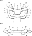
- FIG. 1 is a front view illustrating a boss 4, a rim 1, and spokes 7.
- FIG. 2 is a plan view illustrating the boss 4, the rim 1, and the spokes 7.
- the front surface indicates the surface facing the occupant
- the rear surface indicates the surface positioned on the side opposite the occupant.
- the steering wheel includes the boss 4, rim 1, spokes 7 and cover 8 (see FIG. 4 ).
- the rim 1 and spokes 7 correspond to the steering portion.
- the boss 4 is connected to a steering shaft (not illustrated).
- the boss 4 includes a block-shaped center portion 5 attached to the steering shaft, and protruding parts 6 protruding from both side surfaces of the center portion 5.
- the protruding parts 6 protrude outward in the radial direction of the steering shaft.
- the rim 1 has a U-shape in front view and surrounds the boss 4.
- the spokes 7 are connected to both ends of the rim 1.
- the spokes 7 protrude from both ends of the rim 1 toward the boss 4, and are connected to the center portion 5 of the boss 4 via the protruding parts 6.
- the connecting portion of the rim 1 and the spokes 7 is L-shaped in front view, and the internal angle of the rim 1 and the spokes 7 is an acute angle.
- the protruding parts 6 of the boss 4 are attached to a part of the front surface 7a of the spokes 7.
- the protruding parts 6 may be removed, and the spokes 7 and the boss 4 may be directly connected.
- the rim 1 and spokes 7 include a first region 10, a second region 20, and a third region 30.
- the U-shaped rim 1 includes a bottom portion 2 and two protruding parts 3 protruding from both sides of the bottom portion 2.
- the surface of the bottom portion 2 forms the third region 30.
- the front surface 3a, rear surface 3b, and side surface 3c of the protruding parts 3 of the rim 1 and the front surface 7a and rear surface 7b of the spokes 7 form the first region 10.
- the end surface 3d of the rib and the surface of the spokes 7 (hereinafter referred to as the upper surface 7c) positioned between the end surface 3d and the boss 4 form the second region 20.
- the upper surface 7c of the spokes 7 is positioned between the front surface 7a and the rear surface 7b and is connected to the end surface 3d of the rib.
- the end surface 3d of the rib has a circular shape when viewed from above.
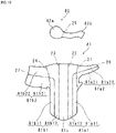
- FIG. 3 is an explanatory diagram illustrating the attachment of the cover 8 to the rim 1 and the spokes 7.
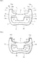
- FIG. 4 is a front view illustrating the steering wheel to which the cover 8 is attached.
- the cover 8 is made of leather and includes two first cover pieces 81, two second cover pieces 82, and one third cover piece 83. Note that the cover 8 may be made of cloth.
- the first cover piece 81 has a sheet shape and corresponds to the shapes of the front surface 3a, rear surface 3b and side surface 3c of the protruding parts 3 of the rim 1 and the shapes of the front surface 7a and the rear surface 7b of the spokes 7.
- the first cover piece 81 includes a front surface portion 81a, a side surface portion 81c, and a rear surface portion 81b.
- a front surface portion 81a and a rear surface portion 81b are connected to both sides of the side surface portion 81c, respectively.
- the broken line of the first cover piece 81 indicates the boundary between the front surface portion 81a and the side surface portion 81c and the boundary between the rear surface portion 81b and the side surface portion 81c.
- the front surface portion 81a is attached to the front surfaces 3a and 7a of the first region 10
- the side surface portion 81c is attached to the side surface 3c of the first region 10
- the rear surface portion 81b is attached to the rear surfaces 3b and 7b of the first region 10.
- the front surface side portion of the side surface portion 81c may be a portion of the front surface portion 81a
- the rear surface side portion of the side surface portion 81c may be a portion of the rear surface portion 81b.
- the boundary between the front surface portion 81a and the rear surface portion 81b is positioned at the center of the side surface portion 81c.
- the first cover piece 81 covers the first region 10 from the outer peripheral side of the rim 1, and the two edges of the first cover piece 81 are joined by stitching on the inner peripheral side of the rim 1, where a seam 41 is formed.
- the second cover piece 82 has a sheet shape and corresponds to the shape of the end surface 3d of the rib and the shape of the upper surface 7c of the spokes 7.
- the portion of the second cover piece 82 attached to the end surface 3d has a circular shape and corresponds to the shape of the end surface 3d.
- the second cover piece 82 is attached to the second region 20, and the edge portion of the second cover piece 82 and the edge portion of the first cover piece 81 are joined by stitching to form a seam 42.
- the third cover piece 83 has a sheet shape and corresponds to the shape of the bottom portion 2. As illustrated in FIG. 4 , the third cover piece 83 covers the third region 30 from the outer peripheral side of the rim 1, and the two edges of the third cover piece 83 are joined by stitching on the inner peripheral side of the rim 1, where a seam 43 is formed. As described above, the steering wheel is manufactured by attaching the cover 8 to the rim 1 and the spokes 7.
- the end portion of the rim 1 and the front surfaces 3a and 7a and the rear surfaces 3b and 7b of the spokes 7 are covered by the first cover piece 81, and the end surface 3d of the rim 1 and upper surface 7c of the spokes 7 are covered by the second cover piece 82. Since the front surfaces 3a and 7a and the rear surfaces 3b and 7b are covered with different cover pieces than the end surface 3d and the upper surface 7c, wrinkles are less readily to occur in the cover 8 at the connecting portion (corner portion) between the rim 1 and the spokes 7, and the cover 8 does not readily loosen.
- the first cover piece 81 and the second cover piece 82 are joined by stitching and are not easily peeled off from the rim 1 and the spokes 7.
- the rim 1 and the spokes 7 are connected in an L shape, so that the operator can easily operate the steering wheel. Since the rim 1 and the spokes 7 are connected at an acute angle, the operator can easily grasp the vicinity of the corner of the steering wheel and easily transmit force to the steering wheel.
- the shape of the second cover piece 82 corresponds to the shape of the end surface 3d of the rim 1, the second cover piece 82 is connected to the first cover piece 81 with no play, and wrinkles are less likely to occur. Moreover, the design is not impaired.
- the leather cover 8 is not slippery and can improve the design.
- a cloth cover 8 can also be used.
- the cloth cover 8 is easily colored, and a variation of the cover 8 can be easily manufactured.
- the two spokes 7 protrude from the two ends of the rim 1, but the two ends of the rim 1 can be connected by one spoke 7 curved so as to protrude toward the boss 4.
- the rim 1 and the spokes 7 have a crescent shape, for example, and the center portion of the spokes 7 is connected to the boss 4.
- the first cover piece 81 and the second cover piece 82 may be configured as follows.
- the first cover piece 81 may correspond to the shapes of the front surface 3a and the side surface 3c of the protruding parts 3 and the shape of the front surface 7a of the spokes 7, and the second cover piece 82 may correspond to the shapes of the rear surface 3b of the protruding parts 3, the rear surface 7b of the spokes 7, the end surface 3d of the rib, and the upper surface 7c of the spokes 7.
- first cover piece 81 may correspond to the shape of the side surface 3c of the first cover piece 81
- second cover piece 82 may correspond to the shapes of the front surface 3a, the end surface 3d and the rear surface 3b of the protruding part 3, and the front surface 7a, the upper surface 7c, and the rear surface 7b of the spokes 7.
- the steering wheel may be configured such that one of the first cover piece 81 and the second cover piece 82 covers one to three of the four surfaces including the front surface, the rear surface, the upper surface, and the side surface of the protruding part 3 and the entirety of the spokes 7, with the remainder being covered by the other of the first cover piece 81 and second cover piece 82.
- FIG. 5 and FIG. 6 are development views illustrating modified examples of the first cover piece 81 and the second cover piece 82 whose configurations are partially modified.
- the side surface portion 81c of the first cover piece 81 and the second cover piece 82 may be connected via the connecting portion 84.
- the rear surface portion 81b of the first cover piece 81 and the second cover piece 82 may be connected via the connecting portion 84.
- the operator folds the connecting portion 84 inward and attaches the edge portions of the first cover piece 81 and the second cover piece 82, respectively, by stitching, covering the rim 1 and the spokes 7.
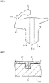
- FIG. 7 is a partially enlarged cross-sectional view illustrating a modified example of the steering wheel whose configuration is partially modified.
- an adhesive may be used to join the first cover piece 81 and the second cover piece 82.
- a groove 70 is formed in the spokes 7 and the rim 1.
- the position of the groove 70 corresponds to the position of the edge portion of each of the first cover piece 81 and the second cover piece 82.
- the operator may insert the edge portions of the first cover piece 81 and the second cover piece 82 into the groove 70, and secure each edge portion to the groove 70 using an adhesive.
- FIG. 8 is a front view illustrating the boss 4, the rim 1, and the spokes 7.
- an end portion 13 protrudes from each protruding part 3 above the upper surface 7c.
- the upper end surface of the end portion 13 forms the end surface 3d.
- the end portion 13 comprises a first side surface 3e.
- the first side surface 3e is connected to the end surface 3d and the upper surface 7c.
- the end portion 13 comprises a second side surface 3f.
- the second side surface 3f is connected to the end surface 3d and the side surface 3c.
- the first side surface 3e and the second side surface 3f are positioned between the front surface 3a and the rear surface 3b.
- the front surface 3a, rear surface 3b, and side surface 3c of the protruding parts 3, the front surface, rear surface and second side surface 3f of the end portion 13, and the front surface 7a and rear surface 7b of the spokes 7 form a first region 10a.
- the end surface 3d, the upper surface 7c, and the first side surface 3e form a second region 20a. From a front view, the position of the end surface 3d in the circumferential direction of the rim 1 corresponds to the discontinuity point.
- FIG. 9 is a front view illustrating the steering wheel to which the cover 8 is attached.
- a first cover piece 181 has a sheet shape, and corresponds to the shapes of the front surface 3a, rear surface 3b, and side surface 3c of the protruding part 3, the front surface, rear surface, and second side surface 3f of the end portion 13, and the front surface 7a and rear surface 7b of the spokes 7.
- the second cover piece 182 has a sheet shape and corresponds to the shape of the end surface 3d, the shape of the first side surface 3e, and the shape of the upper surface 7c of the spokes 7. As illustrated in FIG. 9 , the first cover piece 181 covers the first region 10a, and the second cover piece 182 covers the second region 20a.
- the edge portion of the second cover piece 182 and the edge portion of the first cover piece 181 are joined by stitching to form the seam 42.
- first region 10a and the second region 20a are covered with different cover pieces, wrinkles are less likely to occur on the cover 8 at the connecting portion (corner portion) and the end portion 13 between the rim 1 and the spokes 7, and this decreases the likelihood of the cover 8 loosening.
- FIG. 10 is a front view illustrating the boss 4, the rim 1, and the spokes 7.
- the rim 1 does not have a bottom portion 2, unlike Embodiments 1 and 2.
- the rim 1 includes an arc-shaped rim portion 3k arranged along the periphery of the boss 4.
- the rim portion 3k includes a front surface 3a, a rear surface 3b, an outer peripheral surface 13c, an inner peripheral surface 13d, and an end surface 3d.
- the spokes 7 protrude from the middle portion of the inner peripheral surface 13d.
- a portion of the rim portion 3k protruding above the upper surface 7c forms an end portion 13a.
- the upper end surface of the end portion 13a forms the end surface 3d.
- the front surface 3a, rear surface 3b, outer peripheral surface 13c, front surface 7a, and rear surface 7b of the spokes 7 form a first region 10b.
- the end surface 3d, the upper surface 7c, and the inner peripheral surface 13d above the upper surface 7c form a second region 20b.
- FIG. 11 is a front view illustrating the steering wheel to which the cover 8 is attached.
- the first cover piece 181a has a sheet shape and corresponds to the shapes of the front surface 3a, rear surface 3b, and outer peripheral surface 13c, and the front surface 7a and rear surface 7b of the spokes 7.
- the second cover piece 182a has a sheet shape and corresponds to the shape of the end surface 3d, the upper surface 7c, and the inner peripheral surface 13d above the upper surface 7c.
- the first cover piece 181a covers the first region 10b
- the second cover piece 182a covers the second region 20b.
- the edge portion of the second cover piece 182a and the edge portion of the first cover piece 181ab are joined by stitching to form the seam 42.
- first region 10b and the second region 20b are covered with different cover pieces, wrinkles are less likely to occur on the cover 8 at the connecting portion (corner portion) and at the end portion 13a between the rim portion 3k and the spokes 7, and this decreases the likelihood of the cover 8 loosening.
- the cover 8 includes the separated first cover piece 81 and the second cover piece 82 as in Embodiment 1.
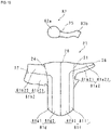
- FIG. 12 is a front view illustrating the first cover piece 81 and the second cover piece 82.
- FIG. 12 corresponds to the first cover piece 81 and the second cover piece 82 arranged on the left side of FIG. 3 .
- the first cover piece 81 may be divided by at least one dividing line among a first dividing line 21, a second dividing line 22, a third dividing line 23, and a fourth dividing line 24. Further, the second cover piece 82 may be divided by a fifth dividing line 25.
- the first dividing line 21 is formed in the region of the front surface portion 81a. As described above, the front surface portion 81a corresponds to the front surface 3a of the protruding parts 3 and the front surface 7a of the spokes 7. The first dividing line 21 is positioned at the boundary between the portion 81a1 corresponding to the front surface 3a and the portion 81a2 corresponding to the front surface 7a in the front surface portion 81a.
- the second dividing line 22 is positioned at the boundary between the front surface portion 81a and the side surface portion 81c.
- the third dividing line 23 is positioned at the boundary between the side surface portion 81c and the rear surface portion 81b.
- the fourth dividing line 24 is formed in the region of the rear surface portion 81b. As described above, the rear surface portion 81b corresponds to the rear surface 3b of the protruding parts 3 and the rear surface 7b of the spokes 7. The fourth dividing line 24 is positioned at the boundary between the portion 81b1 corresponding to the rear surface 3b and the portion 81b2 corresponding to the rear surface 7b in the rear surface portion 81b.
- the second cover piece 82 corresponds to the end surface 3d of the rib and the upper surface 7c of the spokes 7.
- the fifth dividing line 25 is positioned at the boundary between the portion 82a corresponding to the end surface 3d and the portion 82b corresponding to the upper surface 7c in the second cover piece 82.
- the first cover piece 81 and the second cover piece 82 may be divided by at least one of the first dividing line 21 to fifth dividing line 25, and may be divided into 3 to 7 cover portions. Adjacent cover portions are connected to each other by stitching or adhesion. By further dividing the first cover piece 81 or the second cover piece 82, the generation of wrinkles is further suppressed.
- the cover 8 includes the separated first cover piece 81 and the second cover piece 82, and may be divided by the first dividing line 21 to fifth dividing line 25.
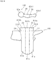
- FIG. 13 is a front view illustrating the first cover piece 81 and the second cover piece 82.
- the first cover piece 81 may be divided by the sixth dividing line 26 or seventh dividing line 27. As illustrated in FIG. 13 , the sixth dividing line 26 is formed in the region of the portion 81a1 corresponding to the front surface 3a and the portion 81a2 corresponding to the front surface 7a.
- the center portion 5 side is referred to as the inside, and the side opposite the center portion 5 is referred to as the outside (see FIG. 1 ).
- the sixth dividing line 26 is positioned at the boundary between the portion 81a11 corresponding to the inner portion of the front surface 3a in the portion 81a1 and the portion 81a12 corresponding to the outer portion of the front surface 3a, and is further positioned at the boundary between the portion 81a21 corresponding to the inner portion of the front surface 7a in the portion 81a2 and the portion 81a22 corresponding to the outer portion of the front surface 7a.
- the seventh dividing line 27 is positioned at the boundary between the portion 81b11 corresponding to the inner portion of the rear surface 3b in the portion 81b1 and the portion 81b12 corresponding to the outer portion of the rear surface 3b, and is further positioned at the boundary between the portion 81b21 corresponding to the inner portion of the rear surface 7b in the portion 81b2 and the portion 81b22 corresponding to the outer portion of the rear surface 7b.
- the first cover piece 81 and the second cover piece 82 are divided by at least one of the first dividing line 21 to seventh dividing line 27, and can be divided into 3 to 11 cover portions. Adjacent cover portions are connected to each other by stitching or adhesion.
- the cover 8 includes the separated first cover piece 81 and the second cover piece 82, and can be divided by the first dividing line 21, fourth dividing line 24, or fifth dividing line 25.
- FIG. 14 is a front view illustrating the first cover piece 81 and the second cover piece 82.
- the first cover piece 81 may be divided by the eight dividing line 28. As illustrated in FIG. 14 , the eight dividing line 28 is positioned at the center of the side surface 3c of the protruding part 3.
- the portion 81f between the first dividing line 21 and the eight dividing line 28 in the first cover piece 81 corresponds to the front surface side portion of the front surface 3a and the side surface 3c of the protruding part.
- the portion 81g between the fourth dividing line 24 and the eight dividing line 28 in the first cover piece 81 corresponds to the rear surface side portion of the rear surface 3b and the side surface 3c of the protruding part.
- the portion 81f corresponds to the front surface of the protruding part 3 and the portion 81g corresponds to the rear surface of the protruding part 3.
- the first cover piece 81 and the second cover piece 82 are separated by at least one of the first dividing line 21, fourth dividing line 24, fifth dividing line 25, and eight dividing line 28, and can be divided into 3 to 6 cover portions. Adjacent cover portions are connected to each other by stitching or adhesion.
- the cover 8 includes the separated first cover piece 81 and the second cover piece 82 as in Embodiment 6, and is divided by the first dividing line 21, fourth dividing line 24, fifth dividing line 25, or eight dividing line 28.
- FIG. 15 is a front view illustrating the first cover piece 81 and the second cover piece 82.
- the first cover piece 81 may be divided by the sixth dividing line 26 or seventh dividing line 27, as in Embodiment 5.
- the sixth dividing line 26 is positioned at the boundary between the portion 81a21 and the portion 81a22, and is further positioned at the boundary between the inner portion 81f1 of the portion 81f and the outer portion 81f2 of the portion 81f.
- the seventh dividing line 27 is positioned at the boundary between the portion 81b21 and the portion 81b22, and is further positioned at the boundary between the inner portion 81g1 of the portion 81g and the outer portion 81g2 of the portion 81g.
- the sixth dividing line 26 is only an example of a line that divides the portion 81a2 and the portion 81f, and a line that divides the portion 81a2 and the portion 81f is not limited to the sixth dividing line 26.
- the seventh dividing line 27 is only an example of a line that divides the portion 81b2 and the portion 81g, and a line that divides the portion 81b2 and the portion 81g is not limited to the seventh dividing line 27.
- the first cover piece 81 and the second cover piece 82 are divided by at least one of the first dividing line 21 and fourth dividing line 24 to eight dividing line 28, and can be divided into 3 to 10 cover portions. Adjacent cover portions are connected to each other by stitching or adhesion.
- the cover 8 includes the separated first cover piece 181 and the second cover piece 182, and is divided by the first dividing line 21 to fifth dividing line 25, as in Embodiment 4.
- FIG. 16 is a front view illustrating the first cover piece 181 and the second cover piece 182.
- the cover 8 covers the boss 4, the rim 1, and the spokes 7 (see FIG. 8 ) of Embodiment 2. Therefore, the cover 8 includes a cover piece 810 that covers the end portion 13 protruding upward from the protruding part 3.
- the cover piece 810 is arranged above the front surface portion 81a, the rear surface portion 81b, and the side surface portion 81c.
- the cover 8 may be divided by the first dividing line 21 to fifth dividing line 25.
- the second dividing line 22 to fourth dividing line 24 extend to the cover piece 810.
- the first cover piece 181 may be divided by a tenth dividing line 210.
- the tenth dividing line 210 is positioned at the boundary between the cover piece 810 and the front surface portion 81a, the rear surface portion 81b, and the side surface portion 81c.
- the cover piece 810 has a portion 810a demarcated by the 10th dividing line 210 and second dividing line 22, a portion 810b demarcated by the 10th dividing line 210, second dividing line 22, and third dividing line 23, and a portion 810c demarcated by the tenth dividing line 210 and third dividing line 23.
- the portion 810a covers the front surface of the end portion 13
- the portion 810b covers the rear surface of the end portion 13
- the portion 810c covers the side surface of the end portion 13.
- the second cover piece 82 may be divided by the fifth dividing line 25 and ninth dividing line 29.
- the fifth dividing line 25 is positioned at the boundary between the portion 82a corresponding to the end surface 3d and the portion 82b1 corresponding to the first side surface 3e.
- the ninth dividing line 29 is positioned at the boundary between the portion 82b1 and the portion 82b2 corresponding to the upper surface 7c.
- At least one of the first dividing line 21 to fifth dividing line 25, ninth dividing line 29, and tenth dividing line 210 divides the first cover piece 181 and second cover piece 182, and can divide them into 3 to 11 cover portions. Adjacent cover portions are connected to each other by stitching or adhesion.
- the cover 8 includes the separated first cover piece 181 and the second cover piece 182 as in Embodiment 8, and is divided by the first dividing line 21 to fifth dividing line 25, the ninth dividing line 29, or the tenth dividing line 210.
- FIG. 17 is a front view illustrating the first cover piece 181 and the second cover piece 182.
- the first cover piece 181 may be further divided by an eleventh dividing line 211 or a twelfth dividing line 212.
- the eleventh dividing line 211 is positioned in the region of the front surface portion 81a and the portion 810a, and may divide the front surface portion 81a and the portion 810a.
- the twelfth dividing line 212 is positioned in the region of the rear surface portion 81b and the portion 810b, and may divide the rear surface portion 81b and the portion 810b.
- At least one of the first dividing line 21 to fifth dividing line 25 and ninth dividing line 29 to twelfth dividing line 212 divides the first cover piece 181 and second cover piece 182, dividing them into 3 to 15 cover portions. Adjacent cover portions are connected to each other by stitching or adhesion.
- FIG. 18 is a front view illustrating the boss 4, the rim 1, and the spokes 7.
- the boss 4, the rim 1, and the spokes 7 according to Embodiment 10 have the same configurations as those of Embodiment 2 except for the upper surface 7c1, the first side surface 3e1, and the end surface 3d1.
- the upper surface 7c1, the first side surface 3e1, and the end surface 3d1 will be described.
- the upper surface 7c1, the first side surface 3e1, and the end surface 3d1 each form a flat square shape.
- the first side surface 3e1 is inclined with respect to the upper surface 7c1 and the end surface 3d1.
- the upper surface 7c1 and the end surface 3d1 are substantially parallel to each other, and the first side surface 3e1, upper surface 7c1, and end surface 3d1 are connected so as to intersect linearly with each other.
- the cover 8 includes the separated first cover piece 181 and the second cover piece 182, and is divided by the first dividing line 21 to fifth dividing line 25, as in Embodiment 4.
- FIG. 19 is a front view illustrating the first cover piece 181 and the second cover piece 182.
- the cover 8 includes a cover piece 810 that covers the end portion 13 protruding upward from the protruding part 3.
- the second dividing line 22 to fourth dividing line 24 extend to the cover piece 810.
- the cover piece 810 has a portion 811a demarcated by the 10th dividing line 210 and 2nd dividing line 22, a portion 811b demarcated by the 10th dividing line 210, second dividing line 22, and 3rd dividing line 23, and a portion 811c demarcated by the tenth dividing line 210 and third dividing line 23.
- the portion 811a covers the front surface of the end portion 13
- the portion 811b covers the rear surface of the end portion 13
- the portion 811c covers the side surface of the end portion 13.
- the second cover piece 82 has a rectangular strip shape and can be divided by the fifth dividing line 25 and ninth dividing line 29.
- the fifth dividing line 25 is positioned at the boundary between the portion 82a1 corresponding to the end surface 3d1 and the portion 82b3 corresponding to the first side surface 3e1.
- the ninth dividing line 29 is positioned at the boundary between the portion 82b3 and the portion 82b4 corresponding to the upper surface 7c1.
- At least one of the first dividing line 21 to fifth dividing line 25, ninth dividing line 29, and tenth dividing line 210 can divide the first cover piece 181 and second cover piece 182, and can divide them into 3 to 11 cover portions. Adjacent cover portions are connected to each other by stitching or adhesion.
- the curved outer edge shape of the first cover piece 81 and the second cover piece 82 may include a shape represented approximately linearly. Further, the curved surfaces of the first cover piece 81 and the second cover piece 82 may include a shape approximately represented by a plane.
Landscapes
- Engineering & Computer Science (AREA)
- Chemical & Material Sciences (AREA)
- Combustion & Propulsion (AREA)
- Transportation (AREA)
- Mechanical Engineering (AREA)
- Steering Controls (AREA)
Abstract
Description
- The present technology relates to a steering wheel.
- Conventionally, a steering wheel in which a circular rim and spokes are covered with a cover has been proposed. The cover includes a plurality of cover pieces, and the plurality of cover pieces are joined by stitching. When attaching the cover to the rim, attach the cover from the outer circumference of the rim with the cover part corresponding to the inner circumference of the rim open, and stitch together the open part. By attaching the cover, the steerability can be improved (see, for example, Patent Document 1).
- In recent years, steering wheels with non-circular rims have been proposed. A non-circular rim has, for example, an acutely curved portion (see, for example, Patent Document 2).
-
- [Patent Document 1]
Japanese Unexamined Patent Publication No. 2015-39900 - [Patent Document 2]
French Patent Application Publication No. 3057532 - When the cover is attached to a non-circular rim by the conventional method, the cover is likely to be wrinkled at the bent portion of the rim, and the cover may be loosened. When the cover moves relative to the rim during steering due to the occurrence and loosening of wrinkles, operator steering is less readily transmitted to the steering wheel.
- In light of the circumstances, an object of the present disclosure is to provide a steering wheel capable of suppressing deterioration of steering ability even if a cover is attached to a non-circular portion of the steering portion.
- The steering wheel according to the present disclosure is a steering wheel including a boss connected to a steering shaft and a steering portion arranged around the boss, where the steering portion has a non-circular portion including a corner portion or an end portion, and the non-circular portion is covered with one or more cover pieces.
- In the present disclosure, a plurality of surfaces constituting the non-circular portion are covered with one or a plurality of cover pieces to prevent wrinkles from being generated on the cover in the non-circular portion.
- In the steering wheel according to the present disclosure, the one or more cover pieces cover the front surface facing the occupant in the non-circular portion, the rear surface positioned on the opposite side of the occupant, and the upper surface positioned between the front surface and the rear surface.
- In the present disclosure, the front, back and top surfaces of the non-circular portion are covered with one or more cover pieces to suppress the occurrence of wrinkles.
- The steering wheel according to the present disclosure includes a first cover piece that covers the front surface and the rear surface, and a second cover piece that is connected to an edge portion of the first cover piece and covers the upper surface of the steering wheel.
- In the present disclosure, the front and rear surfaces are covered by the first cover piece, and the upper surface is covered by the second cover piece. The first cover piece and the second cover piece are connected to each other, which enables the cover to be attached efficiently.
- In the steering wheel according to the present disclosure, the plurality of cover pieces include a first cover piece that covers the front surface and the rear surface, and a second cover piece that covers the upper surface.
- In the present disclosure, the front and rear surfaces are covered by the first cover piece, and the upper surface is covered by the second cover piece. The first cover piece and the second cover piece are separated, and it is easy to suppress the occurrence of wrinkles.
- In the steering wheel according to the present disclosure, at least one of the first cover piece or the second cover piece is divided into a plurality of cover portions.
- In the present disclosure, at least one of the first cover piece and the second cover piece is further divided, and the generation of wrinkles is further suppressed.
- In the steering wheel according to the present disclosure, the steering portion includes a rim arranged around the boss and spokes protruding from the rim toward the boss, where the first cover piece covers the front surface facing the occupant and the rear surface positioned on the opposite side of the occupant, and the second cover piece is arranged on both the front surface and the rear surface and covers the end surfaces of the rim extending from the front surface to the rear surface, and the surface of the spokes arranged between the front surface and rear surface that extend from the end surface of the rim to the boss.
- In the present disclosure, the first cover piece covers the front and rear surfaces of the rim and spokes, and the second cover piece covers the end surface of the rim and the surface of the spokes between the end surface of the rim and the boss. Since the front and rear surfaces and the end surface and the top surface are covered with different cover pieces, wrinkles are less likely to occur on the cover at the connecting portion between the rim and the spokes.
- The steering wheel according to the present disclosure is characterized in that the rim and spokes are connected in an L-shape or a T-shape.
- In the present disclosure, the rims and spokes are connected in an L-shape or a T-shape, so that the operator can easily operate the steering wheel.
- The steering wheel according to the present disclosure is characterized in that the outer edge of the portion of the second cover piece corresponding to the end surface of the rim is formed in a curved shape.
- In the present disclosure, the shape of the second cover piece corresponds to the shape of the end surface of the rim, the second cover piece is connected to the first cover piece without play, and wrinkles are less likely to occur. Moreover, the design is not impaired.
- In the steering wheel according to the present disclosure, the second cover piece has a rectangular strip shape.
- In the present disclosure, the second cover piece covers the surface of the steering portion having a quadrangular shape.
- In the steering wheel according to the present disclosure, the steering portion includes a rim arranged around the boss, and the cover piece covers an end portion of a discontinuity point in the circumferential direction of the outer diameter of the rim.
- In the present disclosure, the cover piece covers the end of a discontinuous rim, for example, an arc-shaped rim that is cut off from a portion of the ring. Therefore, it is easy to suppress wrinkles from being generated on the cover at the end of the rim.
- In the steering wheel according to the present disclosure, the edge portions of the cover pieces are joined by stitching.
- In the present disclosure, the plurality of cover pieces are joined by stitching and are not easily peeled off from the rim and spokes.
- The steering wheel according to the present disclosure is characterized in that the cover piece is made of leather or cloth.
- In the present disclosure, the leather cover is not slippery and can improve the design. The cloth cover is easy to color, and the design of the cover variation can be easily manufactured.
- In the steering wheel according to the present disclosure, since the plurality of surfaces constituting the non-circular portion are covered with different cover pieces, wrinkles are less likely to occur on the cover in the non-circular portion, and the cover is less likely to loosen.
-
-
FIG. 1 is a front view illustrating a boss, a rim, and spokes according to Embodiment 1. -
FIG. 2 is a top view illustrating a boss, a rim, and spokes. -
FIG. 3 is an explanatory diagram illustrating attachment of a cover to a rim and spokes. -
FIG. 4 is a front view illustrating a steering wheel to which a cover is attached. -
FIG. 5 is a development view illustrating a modified example of the first cover piece and the second cover piece whose configuration is partially modified. -
FIG. 6 is a development view illustrating a modified example of the first cover piece and the second cover piece whose configuration is partially modified. -
FIG. 7 is a partially enlarged cross-sectional view illustrating a modified example of a steering wheel whose configuration has been partially modified. -
FIG. 8 is a front view illustrating a boss, a rim, and spokes according to Embodiment 2. -
FIG. 9 is a front view illustrating a steering wheel to which a cover is attached. -
FIG. 10 is a front view illustrating a boss, a rim, and spokes according to Embodiment 3. -
FIG. 11 is a front view illustrating a steering wheel to which a cover is attached. -
FIG. 12 is a front view illustrating a first cover piece and a second cover piece according to Embodiment 4. -
FIG. 13 is a front view illustrating a first cover piece and a second cover piece according to Embodiment 5. -
FIG. 14 is a front view illustrating a first cover piece and a second cover piece according to Embodiment 6. -
FIG. 15 is a front view illustrating a first cover piece and a second cover piece according to Embodiment 7. -
FIG. 16 is a front view illustrating a first cover piece and a second cover piece according toEmbodiment 8. -
FIG. 17 is a front view illustrating a first cover piece and a second cover piece according to Embodiment 9. -
FIG. 18 is a front view illustrating the boss, rim, and spokes according toEmbodiment 10. -
FIG. 19 is a front view illustrating a first cover piece and a second cover piece according toEmbodiment 10. - Hereinafter, the present invention will be described with reference to the drawings illustrating the steering wheel according to the Embodiment.
FIG. 1 is a front view illustrating aboss 4, arim 1, andspokes 7.FIG. 2 is a plan view illustrating theboss 4, therim 1, and thespokes 7. In the following description, the front surface indicates the surface facing the occupant, and the rear surface indicates the surface positioned on the side opposite the occupant. - The steering wheel includes the
boss 4,rim 1,spokes 7 and cover 8 (seeFIG. 4 ). Therim 1 andspokes 7 correspond to the steering portion. Theboss 4 is connected to a steering shaft (not illustrated). As illustrated inFIG. 1 , theboss 4 includes a block-shapedcenter portion 5 attached to the steering shaft, and protrudingparts 6 protruding from both side surfaces of thecenter portion 5. The protrudingparts 6 protrude outward in the radial direction of the steering shaft. - The
rim 1 has a U-shape in front view and surrounds theboss 4. Thespokes 7 are connected to both ends of therim 1. Thespokes 7 protrude from both ends of therim 1 toward theboss 4, and are connected to thecenter portion 5 of theboss 4 via the protrudingparts 6. The connecting portion of therim 1 and thespokes 7 is L-shaped in front view, and the internal angle of therim 1 and thespokes 7 is an acute angle. The protrudingparts 6 of theboss 4 are attached to a part of thefront surface 7a of thespokes 7. The protrudingparts 6 may be removed, and thespokes 7 and theboss 4 may be directly connected. - As illustrated in
FIG. 1 and FIG. 2 , therim 1 andspokes 7 include afirst region 10, asecond region 20, and athird region 30. TheU-shaped rim 1 includes abottom portion 2 and two protrudingparts 3 protruding from both sides of thebottom portion 2. The surface of thebottom portion 2 forms thethird region 30. The front surface 3a,rear surface 3b, andside surface 3c of the protrudingparts 3 of therim 1 and thefront surface 7a andrear surface 7b of thespokes 7 form thefirst region 10. Theend surface 3d of the rib and the surface of the spokes 7 (hereinafter referred to as theupper surface 7c) positioned between theend surface 3d and theboss 4 form thesecond region 20. Theupper surface 7c of thespokes 7 is positioned between thefront surface 7a and therear surface 7b and is connected to theend surface 3d of the rib. Theend surface 3d of the rib has a circular shape when viewed from above. -
FIG. 3 is an explanatory diagram illustrating the attachment of thecover 8 to therim 1 and thespokes 7.FIG. 4 is a front view illustrating the steering wheel to which thecover 8 is attached. Thecover 8 is made of leather and includes twofirst cover pieces 81, twosecond cover pieces 82, and onethird cover piece 83. Note that thecover 8 may be made of cloth. - The
first cover piece 81 has a sheet shape and corresponds to the shapes of the front surface 3a,rear surface 3b andside surface 3c of the protrudingparts 3 of therim 1 and the shapes of thefront surface 7a and therear surface 7b of thespokes 7. Thefirst cover piece 81 includes afront surface portion 81a, aside surface portion 81c, and arear surface portion 81b. Afront surface portion 81a and arear surface portion 81b are connected to both sides of theside surface portion 81c, respectively. InFIG. 3 , the broken line of thefirst cover piece 81 indicates the boundary between thefront surface portion 81a and theside surface portion 81c and the boundary between therear surface portion 81b and theside surface portion 81c. Thefront surface portion 81a is attached to thefront surfaces 3a and 7a of thefirst region 10, theside surface portion 81c is attached to theside surface 3c of thefirst region 10, and therear surface portion 81b is attached to therear surfaces first region 10. - Note, the front surface side portion of the
side surface portion 81c may be a portion of thefront surface portion 81a, and the rear surface side portion of theside surface portion 81c may be a portion of therear surface portion 81b. In this case, for example, the boundary between thefront surface portion 81a and therear surface portion 81b is positioned at the center of theside surface portion 81c. - As illustrated in
FIG. 4 , thefirst cover piece 81 covers thefirst region 10 from the outer peripheral side of therim 1, and the two edges of thefirst cover piece 81 are joined by stitching on the inner peripheral side of therim 1, where aseam 41 is formed. - The
second cover piece 82 has a sheet shape and corresponds to the shape of theend surface 3d of the rib and the shape of theupper surface 7c of thespokes 7. The portion of thesecond cover piece 82 attached to theend surface 3d has a circular shape and corresponds to the shape of theend surface 3d. As illustrated inFIG. 4 , thesecond cover piece 82 is attached to thesecond region 20, and the edge portion of thesecond cover piece 82 and the edge portion of thefirst cover piece 81 are joined by stitching to form aseam 42. - The
third cover piece 83 has a sheet shape and corresponds to the shape of thebottom portion 2. As illustrated inFIG. 4 , thethird cover piece 83 covers thethird region 30 from the outer peripheral side of therim 1, and the two edges of thethird cover piece 83 are joined by stitching on the inner peripheral side of therim 1, where aseam 43 is formed. As described above, the steering wheel is manufactured by attaching thecover 8 to therim 1 and thespokes 7. - In the steering wheel according to
Embodiment 1, the end portion of therim 1 and thefront surfaces 3a and 7a and therear surfaces spokes 7 are covered by thefirst cover piece 81, and theend surface 3d of therim 1 andupper surface 7c of thespokes 7 are covered by thesecond cover piece 82. Since thefront surfaces 3a and 7a and therear surfaces end surface 3d and theupper surface 7c, wrinkles are less readily to occur in thecover 8 at the connecting portion (corner portion) between therim 1 and thespokes 7, and thecover 8 does not readily loosen. - The
first cover piece 81 and thesecond cover piece 82 are joined by stitching and are not easily peeled off from therim 1 and thespokes 7. - Further, the
rim 1 and thespokes 7 are connected in an L shape, so that the operator can easily operate the steering wheel. Since therim 1 and thespokes 7 are connected at an acute angle, the operator can easily grasp the vicinity of the corner of the steering wheel and easily transmit force to the steering wheel. - Further, the shape of the
second cover piece 82 corresponds to the shape of theend surface 3d of therim 1, thesecond cover piece 82 is connected to thefirst cover piece 81 with no play, and wrinkles are less likely to occur. Moreover, the design is not impaired. - Further, the
leather cover 8 is not slippery and can improve the design. Acloth cover 8 can also be used. Thecloth cover 8 is easily colored, and a variation of thecover 8 can be easily manufactured. - In
Embodiment 1, the twospokes 7 protrude from the two ends of therim 1, but the two ends of therim 1 can be connected by one spoke 7 curved so as to protrude toward theboss 4. In this case, therim 1 and thespokes 7 have a crescent shape, for example, and the center portion of thespokes 7 is connected to theboss 4. - The
first cover piece 81 and thesecond cover piece 82 may be configured as follows. Thefirst cover piece 81 may correspond to the shapes of the front surface 3a and theside surface 3c of the protrudingparts 3 and the shape of thefront surface 7a of thespokes 7, and thesecond cover piece 82 may correspond to the shapes of therear surface 3b of the protrudingparts 3, therear surface 7b of thespokes 7, theend surface 3d of the rib, and theupper surface 7c of thespokes 7. - Furthermore, the
first cover piece 81 may correspond to the shape of theside surface 3c of thefirst cover piece 81, and thesecond cover piece 82 may correspond to the shapes of the front surface 3a, theend surface 3d and therear surface 3b of theprotruding part 3, and thefront surface 7a, theupper surface 7c, and therear surface 7b of thespokes 7. - That is to say, that the steering wheel may be configured such that one of the
first cover piece 81 and thesecond cover piece 82 covers one to three of the four surfaces including the front surface, the rear surface, the upper surface, and the side surface of theprotruding part 3 and the entirety of thespokes 7, with the remainder being covered by the other of thefirst cover piece 81 andsecond cover piece 82. -
FIG. 5 andFIG. 6 are development views illustrating modified examples of thefirst cover piece 81 and thesecond cover piece 82 whose configurations are partially modified. As illustrated inFIG. 5 , theside surface portion 81c of thefirst cover piece 81 and thesecond cover piece 82 may be connected via the connectingportion 84. Further, as illustrated inFIG. 6 , therear surface portion 81b of thefirst cover piece 81 and thesecond cover piece 82 may be connected via the connectingportion 84. - When the
first cover piece 81 and thesecond cover piece 82 are connected, for example, the operator folds the connectingportion 84 inward and attaches the edge portions of thefirst cover piece 81 and thesecond cover piece 82, respectively, by stitching, covering therim 1 and thespokes 7. -
FIG. 7 is a partially enlarged cross-sectional view illustrating a modified example of the steering wheel whose configuration is partially modified. As described below, instead of stitching, an adhesive may be used to join thefirst cover piece 81 and thesecond cover piece 82. As illustrated inFIG. 7 , agroove 70 is formed in thespokes 7 and therim 1. The position of thegroove 70 corresponds to the position of the edge portion of each of thefirst cover piece 81 and thesecond cover piece 82. For example, the operator may insert the edge portions of thefirst cover piece 81 and thesecond cover piece 82 into thegroove 70, and secure each edge portion to thegroove 70 using an adhesive. - Hereinafter, the present invention will be described with reference to the drawings illustrating the steering wheel according to
Embodiment 2. Of the configurations according toEmbodiment 2, the same configurations as those ofEmbodiment 1 are designated by the same codes, and detailed descriptions thereof are omitted.FIG. 8 is a front view illustrating theboss 4, therim 1, and thespokes 7. - As illustrated in
FIG. 8 , anend portion 13 protrudes from eachprotruding part 3 above theupper surface 7c. The upper end surface of theend portion 13 forms theend surface 3d. On the opposite side of theside surface 3c, theend portion 13 comprises a first side surface 3e. The first side surface 3e is connected to theend surface 3d and theupper surface 7c. On the opposite side of the first side surface 3e, theend portion 13 comprises a second side surface 3f. The second side surface 3f is connected to theend surface 3d and theside surface 3c. The first side surface 3e and the second side surface 3f are positioned between the front surface 3a and therear surface 3b. - The front surface 3a,
rear surface 3b, andside surface 3c of the protrudingparts 3, the front surface, rear surface and second side surface 3f of theend portion 13, and thefront surface 7a andrear surface 7b of thespokes 7 form a first region 10a. Theend surface 3d, theupper surface 7c, and the first side surface 3e form asecond region 20a. From a front view, the position of theend surface 3d in the circumferential direction of therim 1 corresponds to the discontinuity point. -
FIG. 9 is a front view illustrating the steering wheel to which thecover 8 is attached. Afirst cover piece 181 has a sheet shape, and corresponds to the shapes of the front surface 3a,rear surface 3b, andside surface 3c of theprotruding part 3, the front surface, rear surface, and second side surface 3f of theend portion 13, and thefront surface 7a andrear surface 7b of thespokes 7. Thesecond cover piece 182 has a sheet shape and corresponds to the shape of theend surface 3d, the shape of the first side surface 3e, and the shape of theupper surface 7c of thespokes 7. As illustrated inFIG. 9 , thefirst cover piece 181 covers the first region 10a, and thesecond cover piece 182 covers thesecond region 20a. The edge portion of thesecond cover piece 182 and the edge portion of thefirst cover piece 181 are joined by stitching to form theseam 42. - Since the first region 10a and the
second region 20a are covered with different cover pieces, wrinkles are less likely to occur on thecover 8 at the connecting portion (corner portion) and theend portion 13 between therim 1 and thespokes 7, and this decreases the likelihood of thecover 8 loosening. - Hereinafter, the present invention will be described with reference to the drawings illustrating the steering wheel according to
Embodiment 3. Of the configurations according toEmbodiment 3, the same configurations as those ofEmbodiment FIG. 10 is a front view illustrating theboss 4, therim 1, and thespokes 7. InEmbodiment 3, therim 1 does not have abottom portion 2, unlikeEmbodiments rim 1 includes an arc-shapedrim portion 3k arranged along the periphery of theboss 4. Therim portion 3k includes a front surface 3a, arear surface 3b, an outerperipheral surface 13c, an innerperipheral surface 13d, and anend surface 3d. Thespokes 7 protrude from the middle portion of the innerperipheral surface 13d. A portion of therim portion 3k protruding above theupper surface 7c forms an end portion 13a. The upper end surface of the end portion 13a forms theend surface 3d. - The front surface 3a,
rear surface 3b, outerperipheral surface 13c,front surface 7a, andrear surface 7b of thespokes 7 form afirst region 10b. Theend surface 3d, theupper surface 7c, and the innerperipheral surface 13d above theupper surface 7c form asecond region 20b. -
FIG. 11 is a front view illustrating the steering wheel to which thecover 8 is attached. Thefirst cover piece 181a has a sheet shape and corresponds to the shapes of the front surface 3a,rear surface 3b, and outerperipheral surface 13c, and thefront surface 7a andrear surface 7b of thespokes 7. The second cover piece 182a has a sheet shape and corresponds to the shape of theend surface 3d, theupper surface 7c, and the innerperipheral surface 13d above theupper surface 7c. As illustrated inFIG. 11 , thefirst cover piece 181a covers thefirst region 10b, and the second cover piece 182a covers thesecond region 20b. The edge portion of the second cover piece 182a and the edge portion of the first cover piece 181ab are joined by stitching to form theseam 42. - Since the
first region 10b and thesecond region 20b are covered with different cover pieces, wrinkles are less likely to occur on thecover 8 at the connecting portion (corner portion) and at the end portion 13a between therim portion 3k and thespokes 7, and this decreases the likelihood of thecover 8 loosening. - Hereinafter, the present invention will be described with reference to the drawings illustrating the steering wheel according to
Embodiment 4. Of the configurations according toEmbodiment 4, the same configurations as those ofembodiments 1 to 3 are designated by the same reference numerals, and detailed description thereof will be omitted. InEmbodiment 4, thecover 8 includes the separatedfirst cover piece 81 and thesecond cover piece 82 as inEmbodiment 1.FIG. 12 is a front view illustrating thefirst cover piece 81 and thesecond cover piece 82.FIG. 12 corresponds to thefirst cover piece 81 and thesecond cover piece 82 arranged on the left side ofFIG. 3 . - As illustrated in
FIG. 12 , thefirst cover piece 81 may be divided by at least one dividing line among afirst dividing line 21, asecond dividing line 22, athird dividing line 23, and afourth dividing line 24. Further, thesecond cover piece 82 may be divided by afifth dividing line 25. - The
first dividing line 21 is formed in the region of thefront surface portion 81a. As described above, thefront surface portion 81a corresponds to the front surface 3a of the protrudingparts 3 and thefront surface 7a of thespokes 7. Thefirst dividing line 21 is positioned at the boundary between the portion 81a1 corresponding to the front surface 3a and the portion 81a2 corresponding to thefront surface 7a in thefront surface portion 81a. - The
second dividing line 22 is positioned at the boundary between thefront surface portion 81a and theside surface portion 81c. Thethird dividing line 23 is positioned at the boundary between theside surface portion 81c and therear surface portion 81b. - The
fourth dividing line 24 is formed in the region of therear surface portion 81b. As described above, therear surface portion 81b corresponds to therear surface 3b of the protrudingparts 3 and therear surface 7b of thespokes 7. Thefourth dividing line 24 is positioned at the boundary between the portion 81b1 corresponding to therear surface 3b and the portion 81b2 corresponding to therear surface 7b in therear surface portion 81b. - As described above, the
second cover piece 82 corresponds to theend surface 3d of the rib and theupper surface 7c of thespokes 7. Thefifth dividing line 25 is positioned at the boundary between theportion 82a corresponding to theend surface 3d and theportion 82b corresponding to theupper surface 7c in thesecond cover piece 82. - In
Embodiment 4, thefirst cover piece 81 and thesecond cover piece 82 may be divided by at least one of thefirst dividing line 21 tofifth dividing line 25, and may be divided into 3 to 7 cover portions. Adjacent cover portions are connected to each other by stitching or adhesion. By further dividing thefirst cover piece 81 or thesecond cover piece 82, the generation of wrinkles is further suppressed. - Hereinafter, the present invention will be described with reference to the drawings illustrating the steering wheel according to
Embodiment 5. Of the configurations according toEmbodiment 5, the same configurations as those ofEmbodiment 1 to 4 are designated by the same codes, and detailed descriptions thereof are omitted. InEmbodiment 5, similar toEmbodiment 4, thecover 8 includes the separatedfirst cover piece 81 and thesecond cover piece 82, and may be divided by thefirst dividing line 21 tofifth dividing line 25.FIG. 13 is a front view illustrating thefirst cover piece 81 and thesecond cover piece 82. - The
first cover piece 81 may be divided by thesixth dividing line 26 orseventh dividing line 27. As illustrated inFIG. 13 , thesixth dividing line 26 is formed in the region of the portion 81a1 corresponding to the front surface 3a and the portion 81a2 corresponding to thefront surface 7a. In the following description, thecenter portion 5 side is referred to as the inside, and the side opposite thecenter portion 5 is referred to as the outside (seeFIG. 1 ). Thesixth dividing line 26 is positioned at the boundary between the portion 81a11 corresponding to the inner portion of the front surface 3a in the portion 81a1 and the portion 81a12 corresponding to the outer portion of the front surface 3a, and is further positioned at the boundary between the portion 81a21 corresponding to the inner portion of thefront surface 7a in the portion 81a2 and the portion 81a22 corresponding to the outer portion of thefront surface 7a. - The
seventh dividing line 27 is positioned at the boundary between the portion 81b11 corresponding to the inner portion of therear surface 3b in the portion 81b1 and the portion 81b12 corresponding to the outer portion of therear surface 3b, and is further positioned at the boundary between the portion 81b21 corresponding to the inner portion of therear surface 7b in the portion 81b2 and the portion 81b22 corresponding to the outer portion of therear surface 7b. - In
Embodiment 5, thefirst cover piece 81 and thesecond cover piece 82 are divided by at least one of thefirst dividing line 21 toseventh dividing line 27, and can be divided into 3 to 11 cover portions. Adjacent cover portions are connected to each other by stitching or adhesion. - Hereinafter, the present invention will be described with reference to the drawings illustrating the steering wheel according to
Embodiment 6. Of the configurations according toEmbodiment 6, the same configurations as those ofEmbodiments 1 to 5 are designated by the same reference numerals, and detailed description thereof will be omitted. InEmbodiment 6, as inEmbodiment 4, thecover 8 includes the separatedfirst cover piece 81 and thesecond cover piece 82, and can be divided by thefirst dividing line 21,fourth dividing line 24, orfifth dividing line 25.FIG. 14 is a front view illustrating thefirst cover piece 81 and thesecond cover piece 82. - The
first cover piece 81 may be divided by the eight dividingline 28. As illustrated inFIG. 14 , the eight dividingline 28 is positioned at the center of theside surface 3c of theprotruding part 3. Theportion 81f between thefirst dividing line 21 and the eight dividingline 28 in thefirst cover piece 81 corresponds to the front surface side portion of the front surface 3a and theside surface 3c of the protruding part. Theportion 81g between thefourth dividing line 24 and the eight dividingline 28 in thefirst cover piece 81 corresponds to the rear surface side portion of therear surface 3b and theside surface 3c of the protruding part. - Since the front surface side portion of the
side surface 3c can be regarded as a part of the front surface 3a and the rear surface side portion of theside surface 3c can be regarded as a part of therear surface 3b, theportion 81f corresponds to the front surface of theprotruding part 3 and theportion 81g corresponds to the rear surface of theprotruding part 3. - In
Embodiment 6, thefirst cover piece 81 and thesecond cover piece 82 are separated by at least one of thefirst dividing line 21,fourth dividing line 24,fifth dividing line 25, and eight dividingline 28, and can be divided into 3 to 6 cover portions. Adjacent cover portions are connected to each other by stitching or adhesion. - Hereinafter, the present invention will be described with reference to the drawings illustrating the steering wheel according to
Embodiment 7. Of the configurations according toEmbodiment 7, the same configurations as those ofEmbodiments 1 to 6 are designated by the same reference numerals, and detailed description thereof will be omitted. InEmbodiment 7, thecover 8 includes the separatedfirst cover piece 81 and thesecond cover piece 82 as inEmbodiment 6, and is divided by thefirst dividing line 21,fourth dividing line 24,fifth dividing line 25, or eight dividingline 28.FIG. 15 is a front view illustrating thefirst cover piece 81 and thesecond cover piece 82. - The
first cover piece 81 may be divided by thesixth dividing line 26 orseventh dividing line 27, as inEmbodiment 5. As illustrated inFIG. 15 , thesixth dividing line 26 is positioned at the boundary between the portion 81a21 and the portion 81a22, and is further positioned at the boundary between the inner portion 81f1 of theportion 81f and the outer portion 81f2 of theportion 81f. Theseventh dividing line 27 is positioned at the boundary between the portion 81b21 and the portion 81b22, and is further positioned at the boundary between the inner portion 81g1 of theportion 81g and the outer portion 81g2 of theportion 81g. - The
sixth dividing line 26 is only an example of a line that divides the portion 81a2 and theportion 81f, and a line that divides the portion 81a2 and theportion 81f is not limited to thesixth dividing line 26. Further, theseventh dividing line 27 is only an example of a line that divides the portion 81b2 and theportion 81g, and a line that divides the portion 81b2 and theportion 81g is not limited to theseventh dividing line 27. - In
Embodiment 7, thefirst cover piece 81 and thesecond cover piece 82 are divided by at least one of thefirst dividing line 21 andfourth dividing line 24 to eight dividingline 28, and can be divided into 3 to 10 cover portions. Adjacent cover portions are connected to each other by stitching or adhesion. - Hereinafter, the present invention will be described with reference to the drawings illustrating the steering wheel according to
Embodiment 8. Of the configurations according toEmbodiment 8, the same configurations as those ofEmbodiments 1 to 7 are designated by the same reference numerals, and a detailed description thereof will be omitted. InEmbodiment 8, thecover 8 includes the separatedfirst cover piece 181 and thesecond cover piece 182, and is divided by thefirst dividing line 21 tofifth dividing line 25, as inEmbodiment 4.FIG. 16 is a front view illustrating thefirst cover piece 181 and thesecond cover piece 182. - The
cover 8 covers theboss 4, therim 1, and the spokes 7 (seeFIG. 8 ) ofEmbodiment 2. Therefore, thecover 8 includes acover piece 810 that covers theend portion 13 protruding upward from the protrudingpart 3. - As illustrated in
FIG. 16 , thecover piece 810 is arranged above thefront surface portion 81a, therear surface portion 81b, and theside surface portion 81c. Thecover 8 may be divided by thefirst dividing line 21 tofifth dividing line 25. Thesecond dividing line 22 tofourth dividing line 24 extend to thecover piece 810. - The
first cover piece 181 may be divided by atenth dividing line 210. Thetenth dividing line 210 is positioned at the boundary between thecover piece 810 and thefront surface portion 81a, therear surface portion 81b, and theside surface portion 81c. Thecover piece 810 has aportion 810a demarcated by the10th dividing line 210 andsecond dividing line 22, aportion 810b demarcated by the10th dividing line 210,second dividing line 22, andthird dividing line 23, and aportion 810c demarcated by thetenth dividing line 210 andthird dividing line 23. Theportion 810a covers the front surface of theend portion 13, theportion 810b covers the rear surface of theend portion 13, and theportion 810c covers the side surface of theend portion 13. - The
second cover piece 82 may be divided by thefifth dividing line 25 andninth dividing line 29. Thefifth dividing line 25 is positioned at the boundary between theportion 82a corresponding to theend surface 3d and the portion 82b1 corresponding to the first side surface 3e. Theninth dividing line 29 is positioned at the boundary between the portion 82b1 and the portion 82b2 corresponding to theupper surface 7c. - In
Embodiment 8, at least one of thefirst dividing line 21 tofifth dividing line 25,ninth dividing line 29, andtenth dividing line 210 divides thefirst cover piece 181 andsecond cover piece 182, and can divide them into 3 to 11 cover portions. Adjacent cover portions are connected to each other by stitching or adhesion. - Hereinafter, the present invention will be described with reference to the drawings illustrating the steering wheel according to Embodiment 9. Of the configurations according to Embodiment 9, the same configurations as those of
Embodiments 1 to 8 are designated by the same reference numerals, and a detailed description thereof will be omitted. In Embodiment 9, thecover 8 includes the separatedfirst cover piece 181 and thesecond cover piece 182 as inEmbodiment 8, and is divided by thefirst dividing line 21 tofifth dividing line 25, theninth dividing line 29, or thetenth dividing line 210.FIG. 17 is a front view illustrating thefirst cover piece 181 and thesecond cover piece 182. - As illustrated in
FIG. 17 , thefirst cover piece 181 may be further divided by aneleventh dividing line 211 or atwelfth dividing line 212. Theeleventh dividing line 211 is positioned in the region of thefront surface portion 81a and theportion 810a, and may divide thefront surface portion 81a and theportion 810a. - The
twelfth dividing line 212 is positioned in the region of therear surface portion 81b and theportion 810b, and may divide therear surface portion 81b and theportion 810b. - In Embodiment 9, at least one of the
first dividing line 21 tofifth dividing line 25 andninth dividing line 29 totwelfth dividing line 212 divides thefirst cover piece 181 andsecond cover piece 182, dividing them into 3 to 15 cover portions. Adjacent cover portions are connected to each other by stitching or adhesion. - Hereinafter, the present invention will be described with reference to the drawings illustrating the steering wheel according to
Embodiment 10. Of the configurations according toEmbodiment 10, the same configurations as those ofEmbodiments 1 to 9 are designated by the same reference numerals, and a detailed description thereof will be omitted.FIG. 18 is a front view illustrating theboss 4, therim 1, and thespokes 7. Theboss 4, therim 1, and thespokes 7 according toEmbodiment 10 have the same configurations as those ofEmbodiment 2 except for the upper surface 7c1, the first side surface 3e1, and the end surface 3d1. Here, the upper surface 7c1, the first side surface 3e1, and the end surface 3d1 will be described. - The upper surface 7c1, the first side surface 3e1, and the end surface 3d1 each form a flat square shape. The first side surface 3e1 is inclined with respect to the upper surface 7c1 and the end surface 3d1. As illustrated in
FIG. 18 , the upper surface 7c1 and the end surface 3d1 are substantially parallel to each other, and the first side surface 3e1, upper surface 7c1, and end surface 3d1 are connected so as to intersect linearly with each other. - The
cover 8 includes the separatedfirst cover piece 181 and thesecond cover piece 182, and is divided by thefirst dividing line 21 tofifth dividing line 25, as inEmbodiment 4.FIG. 19 is a front view illustrating thefirst cover piece 181 and thesecond cover piece 182. Thecover 8 includes acover piece 810 that covers theend portion 13 protruding upward from the protrudingpart 3. Thesecond dividing line 22 tofourth dividing line 24 extend to thecover piece 810. - The
cover piece 810 has aportion 811a demarcated by the10th dividing line 210 and2nd dividing line 22, aportion 811b demarcated by the10th dividing line 210,second dividing line 22, and3rd dividing line 23, and aportion 811c demarcated by thetenth dividing line 210 andthird dividing line 23. Theportion 811a covers the front surface of theend portion 13, theportion 811b covers the rear surface of theend portion 13, and theportion 811c covers the side surface of theend portion 13. - The
second cover piece 82 has a rectangular strip shape and can be divided by thefifth dividing line 25 andninth dividing line 29. Thefifth dividing line 25 is positioned at the boundary between the portion 82a1 corresponding to the end surface 3d1 and the portion 82b3 corresponding to the first side surface 3e1. Theninth dividing line 29 is positioned at the boundary between the portion 82b3 and the portion 82b4 corresponding to the upper surface 7c1. - In
Embodiment 10, at least one of thefirst dividing line 21 tofifth dividing line 25,ninth dividing line 29, andtenth dividing line 210 can divide thefirst cover piece 181 andsecond cover piece 182, and can divide them into 3 to 11 cover portions. Adjacent cover portions are connected to each other by stitching or adhesion. - In each of the Embodiments described above, the curved outer edge shape of the
first cover piece 81 and thesecond cover piece 82 may include a shape represented approximately linearly. Further, the curved surfaces of thefirst cover piece 81 and thesecond cover piece 82 may include a shape approximately represented by a plane. - When a reference code is noted in a claim, the reference code is merely provided as a reference in correspondence with the reference code described in the embodiment in order to facilitate understanding of the claim. The scope of claims is not limited to the embodiments.
- The embodiments presently disclosed are to be considered as examples for all points, and are not restrictive. The technical features described in the examples can be combined with each other, and the scope of the invention is intended to include all changes within the scope of the claims and a scope equal to the claims.
-
- 1: Rim
- 3: Protruding part
- 3a: Front surface
- 3b: Rear surface
- 3d: End surface
- 4: Boss
- 7: Spokes
- 7a: Front surface
- 7b: Rear surface
- 7c: Upper surface
- 8: Cover
- 81: First cover piece
- 82: Second cover piece
- 83: Third cover piece
Claims (12)
- A steering wheel, comprising:a boss connected to a steering shaft and a steering portion arranged around the boss, whereinthe steering portion has a non-circular portion including a corner portion or an end portion, and the non-circular portion is covered with one or more cover pieces.
- The steering wheel according to claim 1, wherein the one or more cover pieces cover the front surface facing the occupant in the non-circular portion, the rear surface is positioned on the side opposite the occupant, and the upper surface is positioned between the front surface and the rear surface.
- The steering wheel according to claim 2, comprising:a first cover piece that covers the front surface and the rear surface; anda second cover piece that is connected to an edge portion of the first cover piece and covers the upper surface.
- The steering wheel according to claim 2, wherein the plurality of cover pieces include a first cover piece that covers the front surface and the rear surface, and a second cover piece that covers the upper surface.
- The steering wheel according to claim 4, wherein at least one of the first cover piece and the second cover piece is divided into a plurality of cover portions.
- The steering wheel according to any one of claims 3 to 5, whereinthe steering portion includes a rim arranged around the boss and spokes protruding from the rim toward the boss,the first cover piece covers the front surface facing the occupant and the rear surface positioned on the side opposite the occupant, andthe second cover piece is arranged on both the front surface and the rear surface, and covers the end surfaces of the rim extending from the front surface to the rear surface and the surface of the spokes arranged between the front surface and rear surface that extend between the end surface of the rim and the boss.
- The steering wheel according to claim 6, wherein the rim and spokes are connected in an L-shape or a T-shape.
- The steering wheel according to claim 6 or 7, wherein the outer edge of the portion of the second cover piece corresponding to the end surface of the rim is formed in a curved shape.
- The steering wheel according to claim 6 or 7, wherein the second cover piece has a rectangular strip shape.
- The steering wheel according to any one of claims 3 to 5, wherein the steering portion includes a rim arranged around the boss, and the cover piece covers an end portion of a discontinuity point in the circumferential direction of the outer diameter of the rim.
- The steering wheel according to any one of claims 1 to 10, wherein the edge portions of the cover pieces are connected by stitching.
- The steering wheel according to any one of claims 1 to 11, wherein the cover piece is made of leather or cloth.
Applications Claiming Priority (2)
| Application Number | Priority Date | Filing Date | Title |
|---|---|---|---|
| JP2019229288 | 2019-12-19 | ||
| PCT/JP2020/039922 WO2021124678A1 (en) | 2019-12-19 | 2020-10-23 | Steering wheel |
Publications (2)
| Publication Number | Publication Date |
|---|---|
| EP4079604A1 true EP4079604A1 (en) | 2022-10-26 |
| EP4079604A4 EP4079604A4 (en) | 2024-01-10 |
Family
ID=76477203
Family Applications (1)
| Application Number | Title | Priority Date | Filing Date |
|---|---|---|---|
| EP20902800.0A Pending EP4079604A4 (en) | 2019-12-19 | 2020-10-23 | Steering wheel |
Country Status (6)
| Country | Link |
|---|---|
| US (1) | US11938995B2 (en) |
| EP (1) | EP4079604A4 (en) |
| JP (1) | JP7303331B2 (en) |
| KR (1) | KR102702636B1 (en) |
| CN (1) | CN114728667B (en) |
| WO (1) | WO2021124678A1 (en) |
Families Citing this family (4)
| Publication number | Priority date | Publication date | Assignee | Title |
|---|---|---|---|---|
| USD1110907S1 (en) * | 2022-02-21 | 2026-02-03 | Gordon Murray Automotive Limited | Steering wheel |
| JP7630485B2 (en) * | 2022-12-27 | 2025-02-17 | 本田技研工業株式会社 | Steering Wheel |
| JP7630486B2 (en) | 2022-12-27 | 2025-02-17 | 本田技研工業株式会社 | Steering Wheel |
| JP7445033B1 (en) | 2023-01-31 | 2024-03-06 | 丸山 徹 | Steering member |
Family Cites Families (33)
| Publication number | Priority date | Publication date | Assignee | Title |
|---|---|---|---|---|
| GB2189755B (en) | 1986-05-01 | 1989-11-29 | Moto Lita Ltd | An improved vehicle steering-wheel |
| JPH01159434A (en) | 1987-12-16 | 1989-06-22 | Mazda Motor Corp | Controller for fuel-injection engine |
| JPH0716542Y2 (en) * | 1989-06-08 | 1995-04-19 | 豊田合成株式会社 | Skin-wrapped steering wheel |
| CA2200820C (en) | 1996-03-25 | 2000-04-11 | Grant Products | Steering wheel overlay |
| JP3197005B2 (en) * | 1997-08-27 | 2001-08-13 | 本田技研工業株式会社 | Vehicle steering wheel |
| JP3518996B2 (en) | 1998-07-29 | 2004-04-12 | ミドリ安全株式会社 | Leather-coated steering wheel |
| JP3842096B2 (en) * | 2001-10-10 | 2006-11-08 | 本田技研工業株式会社 | Vehicle steering wheel |
| US6997281B2 (en) * | 2002-11-26 | 2006-02-14 | General Motors Corporation | Driver control input device for drive-by-wire vehicle |
| JP3726820B2 (en) * | 2003-04-04 | 2005-12-14 | スズキ株式会社 | Handle structure of small electric vehicle |
| US7441799B2 (en) * | 2003-12-08 | 2008-10-28 | Autoliv Asp, Inc. | Non-circular steering wheel assembly and airbag module |
| JP2005312728A (en) * | 2004-04-30 | 2005-11-10 | Midori Anzen Co Ltd | Leather, shift knob and steering wheel |
| MX2007013387A (en) * | 2005-04-27 | 2008-03-14 | Midori Anzen Co Ltd | Leather and process for producing leather. |
| DE102006010155A1 (en) * | 2006-02-27 | 2007-09-13 | Takata-Petri Ag | A method of manufacturing a steering wheel and steering wheel made by the method |
| JP4241799B2 (en) * | 2006-10-16 | 2009-03-18 | トヨタ自動車株式会社 | Vehicle steering device |
| US20110167953A1 (en) * | 2010-01-14 | 2011-07-14 | Takamori Enterprise Co., Ltd. | Automobile steering wheel |
| DE102010063440A1 (en) | 2010-12-17 | 2012-06-21 | Takata-Petri Ag | Method for producing a steering wheel and enclosure for wrapping a steering wheel rim of a steering wheel |
| JP6117046B2 (en) * | 2013-07-30 | 2017-04-19 | 日本プラスト株式会社 | handle |
| JP6064835B2 (en) | 2013-08-20 | 2017-01-25 | マツダ株式会社 | Leather winding grip structure for automobiles |
| KR101522096B1 (en) | 2013-10-04 | 2015-05-20 | 주식회사 포스코 | Waste gas valve for removing foreign substance |
| CN203651868U (en) * | 2013-11-04 | 2014-06-18 | 欧阳晓民 | Improved Structure of Steering Wheel Grip |
| JP6032188B2 (en) * | 2013-11-29 | 2016-11-24 | 豊田合成株式会社 | Decorative product with clear layer and method for forming the same |
| JP6123686B2 (en) * | 2014-01-10 | 2017-05-10 | 豊田合成株式会社 | Steering wheel |
| JP6356509B2 (en) * | 2014-07-09 | 2018-07-11 | 日本プラスト株式会社 | handle |
| CN204415497U (en) * | 2015-01-26 | 2015-06-24 | 重庆义唐贸易有限公司 | The solid forming automobile steering wheel cover of safe healthcare |
| FR3057532B1 (en) | 2016-10-17 | 2019-04-12 | Renault S.A.S | FLYWHEEL FOR AUTONOMOUS MOTOR VEHICLE. |
| EP3335915B1 (en) * | 2016-12-13 | 2019-12-04 | AeroMobil R&D, s. r. o. | Stability control for operation of a convertible air - road vehicle |
| US20180229752A1 (en) * | 2017-02-16 | 2018-08-16 | Ford Global Technologies, Llc | Heated steering wheel system |
| JP6990611B2 (en) | 2018-03-23 | 2022-01-12 | 日本プラスト株式会社 | Covering member for handle, handle, and manufacturing method of handle |
| JP7014039B2 (en) | 2018-05-10 | 2022-02-15 | トヨタ自動車株式会社 | Steering device for vehicles |
| US10836420B2 (en) * | 2018-10-03 | 2020-11-17 | Po-Jen Lai | Steering wheel sheath with composite structure |
| JP7060494B2 (en) * | 2018-11-21 | 2022-04-26 | 豊田合成株式会社 | Steering wheel |
| CN209290476U (en) * | 2018-12-31 | 2019-08-23 | 青岛龙翔机械制造有限公司 | A premium auto accessory for new drivetrains |
| WO2021053982A1 (en) * | 2019-09-17 | 2021-03-25 | オートリブ ディベロップメント エービー | Driver seat airbag device |
-
2020
- 2020-10-23 KR KR1020227024252A patent/KR102702636B1/en active Active
- 2020-10-23 CN CN202080080232.6A patent/CN114728667B/en active Active
- 2020-10-23 JP JP2021565345A patent/JP7303331B2/en active Active
- 2020-10-23 WO PCT/JP2020/039922 patent/WO2021124678A1/en not_active Ceased
- 2020-10-23 US US17/757,534 patent/US11938995B2/en active Active
- 2020-10-23 EP EP20902800.0A patent/EP4079604A4/en active Pending
Also Published As
| Publication number | Publication date |
|---|---|
| US20230082806A1 (en) | 2023-03-16 |
| JPWO2021124678A1 (en) | 2021-06-24 |
| KR102702636B1 (en) | 2024-09-06 |
| WO2021124678A1 (en) | 2021-06-24 |
| CN114728667A (en) | 2022-07-08 |
| EP4079604A4 (en) | 2024-01-10 |
| CN114728667B (en) | 2023-12-29 |
| JP7303331B2 (en) | 2023-07-04 |
| KR20220110306A (en) | 2022-08-05 |
| US11938995B2 (en) | 2024-03-26 |
Similar Documents
| Publication | Publication Date | Title |
|---|---|---|
| US11938995B2 (en) | Steering wheel | |
| US9302535B2 (en) | Automobile wheel | |
| JP6125998B2 (en) | Wheel disc for vehicle | |
| US9248801B2 (en) | Cover element composed of plastic for a driver's airbag module and cover consisting of such a cover element and a casing arranged on the latter | |
| US20130026746A1 (en) | Vehicle body structure for automobile | |
| MX2023011089A (en) | Lid element and closure assembly for a beverage container. | |
| US2368246A (en) | Wheel structure | |
| US6443030B1 (en) | Vehicle steering wheel | |
| US20190070894A1 (en) | Vehicle wheel | |
| KR20160048588A (en) | Reflecting mirror for road | |
| CN108602536A (en) | Device for being fastened to mud guard on the vehicle body of motor vehicles | |
| US3013639A (en) | Air circulation wheel structure | |
| EP1736325B1 (en) | Hubcap or wheel cover unit | |
| JP5623373B2 (en) | Wheel cap | |
| US2386245A (en) | Wheel structure | |
| US2842405A (en) | Wheel cover | |
| CN210760044U (en) | Wheel of vehicle | |
| US2857025A (en) | Wheel structure | |
| JP6578578B2 (en) | Method of attaching vehicle wheel and balance weight to vehicle wheel | |
| US3025111A (en) | Wheel cover | |
| US2148210A (en) | Ornamental wheel disk | |
| US2664318A (en) | Wheel cover | |
| US2414824A (en) | Wheel structure | |
| US2597882A (en) | Hubcap | |
| KR200464500Y1 (en) | A handle cover for automobile |
Legal Events
| Date | Code | Title | Description |
|---|---|---|---|
| STAA | Information on the status of an ep patent application or granted ep patent |
Free format text: STATUS: THE INTERNATIONAL PUBLICATION HAS BEEN MADE |
|
| PUAI | Public reference made under article 153(3) epc to a published international application that has entered the european phase |
Free format text: ORIGINAL CODE: 0009012 |
|
| STAA | Information on the status of an ep patent application or granted ep patent |
Free format text: STATUS: REQUEST FOR EXAMINATION WAS MADE |
|
| 17P | Request for examination filed |
Effective date: 20220708 |
|
| AK | Designated contracting states |
Kind code of ref document: A1 Designated state(s): AL AT BE BG CH CY CZ DE DK EE ES FI FR GB GR HR HU IE IS IT LI LT LU LV MC MK MT NL NO PL PT RO RS SE SI SK SM TR |
|
| DAV | Request for validation of the european patent (deleted) | ||
| DAX | Request for extension of the european patent (deleted) | ||
| A4 | Supplementary search report drawn up and despatched |
Effective date: 20231208 |
|
| RIC1 | Information provided on ipc code assigned before grant |
Ipc: B62D 1/04 20060101AFI20231204BHEP |