EP4079590A1 - Electronic brake system and control method therefor - Google Patents
Electronic brake system and control method therefor Download PDFInfo
- Publication number
- EP4079590A1 EP4079590A1 EP21743675.7A EP21743675A EP4079590A1 EP 4079590 A1 EP4079590 A1 EP 4079590A1 EP 21743675 A EP21743675 A EP 21743675A EP 4079590 A1 EP4079590 A1 EP 4079590A1
- Authority
- EP
- European Patent Office
- Prior art keywords
- motor
- hydraulic
- excitation current
- controller
- abs
- Prior art date
- Legal status (The legal status is an assumption and is not a legal conclusion. Google has not performed a legal analysis and makes no representation as to the accuracy of the status listed.)
- Granted
Links
Images



Classifications
-
- B—PERFORMING OPERATIONS; TRANSPORTING
- B60—VEHICLES IN GENERAL
- B60T—VEHICLE BRAKE CONTROL SYSTEMS OR PARTS THEREOF; BRAKE CONTROL SYSTEMS OR PARTS THEREOF, IN GENERAL; ARRANGEMENT OF BRAKING ELEMENTS ON VEHICLES IN GENERAL; PORTABLE DEVICES FOR PREVENTING UNWANTED MOVEMENT OF VEHICLES; VEHICLE MODIFICATIONS TO FACILITATE COOLING OF BRAKES
- B60T8/00—Arrangements for adjusting wheel-braking force to meet varying vehicular or ground-surface conditions, e.g. limiting or varying distribution of braking force
- B60T8/17—Using electrical or electronic regulation means to control braking
- B60T8/176—Brake regulation specially adapted to prevent excessive wheel slip during vehicle deceleration, e.g. ABS
-
- B—PERFORMING OPERATIONS; TRANSPORTING
- B60—VEHICLES IN GENERAL
- B60T—VEHICLE BRAKE CONTROL SYSTEMS OR PARTS THEREOF; BRAKE CONTROL SYSTEMS OR PARTS THEREOF, IN GENERAL; ARRANGEMENT OF BRAKING ELEMENTS ON VEHICLES IN GENERAL; PORTABLE DEVICES FOR PREVENTING UNWANTED MOVEMENT OF VEHICLES; VEHICLE MODIFICATIONS TO FACILITATE COOLING OF BRAKES
- B60T7/00—Brake-action initiating means
- B60T7/02—Brake-action initiating means for personal initiation
- B60T7/04—Brake-action initiating means for personal initiation foot actuated
- B60T7/042—Brake-action initiating means for personal initiation foot actuated by electrical means, e.g. using travel or force sensors
-
- B—PERFORMING OPERATIONS; TRANSPORTING
- B60—VEHICLES IN GENERAL
- B60W—CONJOINT CONTROL OF VEHICLE SUB-UNITS OF DIFFERENT TYPE OR DIFFERENT FUNCTION; CONTROL SYSTEMS SPECIALLY ADAPTED FOR HYBRID VEHICLES; ROAD VEHICLE DRIVE CONTROL SYSTEMS FOR PURPOSES NOT RELATED TO THE CONTROL OF A PARTICULAR SUB-UNIT
- B60W50/00—Details of control systems for road vehicle drive control not related to the control of a particular sub-unit, e.g. process diagnostic or vehicle driver interfaces
- B60W50/08—Interaction between the driver and the control system
- B60W50/14—Means for informing the driver, warning the driver or prompting a driver intervention
- B60W50/16—Tactile feedback to the driver, e.g. vibration or force feedback to the driver on the steering wheel or the accelerator pedal
-
- B—PERFORMING OPERATIONS; TRANSPORTING
- B60—VEHICLES IN GENERAL
- B60T—VEHICLE BRAKE CONTROL SYSTEMS OR PARTS THEREOF; BRAKE CONTROL SYSTEMS OR PARTS THEREOF, IN GENERAL; ARRANGEMENT OF BRAKING ELEMENTS ON VEHICLES IN GENERAL; PORTABLE DEVICES FOR PREVENTING UNWANTED MOVEMENT OF VEHICLES; VEHICLE MODIFICATIONS TO FACILITATE COOLING OF BRAKES
- B60T13/00—Transmitting braking action from initiating means to ultimate brake actuator with power assistance or drive; Brake systems incorporating such transmitting means, e.g. air-pressure brake systems
- B60T13/10—Transmitting braking action from initiating means to ultimate brake actuator with power assistance or drive; Brake systems incorporating such transmitting means, e.g. air-pressure brake systems with fluid assistance, drive, or release
- B60T13/12—Transmitting braking action from initiating means to ultimate brake actuator with power assistance or drive; Brake systems incorporating such transmitting means, e.g. air-pressure brake systems with fluid assistance, drive, or release the fluid being liquid
- B60T13/16—Transmitting braking action from initiating means to ultimate brake actuator with power assistance or drive; Brake systems incorporating such transmitting means, e.g. air-pressure brake systems with fluid assistance, drive, or release the fluid being liquid using pumps directly, i.e. without interposition of accumulators or reservoirs
- B60T13/161—Systems with master cylinder
- B60T13/165—Master cylinder integrated or hydraulically coupled with booster
- B60T13/166—Part of the system directly actuated by booster pressure
-
- B—PERFORMING OPERATIONS; TRANSPORTING
- B60—VEHICLES IN GENERAL
- B60T—VEHICLE BRAKE CONTROL SYSTEMS OR PARTS THEREOF; BRAKE CONTROL SYSTEMS OR PARTS THEREOF, IN GENERAL; ARRANGEMENT OF BRAKING ELEMENTS ON VEHICLES IN GENERAL; PORTABLE DEVICES FOR PREVENTING UNWANTED MOVEMENT OF VEHICLES; VEHICLE MODIFICATIONS TO FACILITATE COOLING OF BRAKES
- B60T13/00—Transmitting braking action from initiating means to ultimate brake actuator with power assistance or drive; Brake systems incorporating such transmitting means, e.g. air-pressure brake systems
- B60T13/74—Transmitting braking action from initiating means to ultimate brake actuator with power assistance or drive; Brake systems incorporating such transmitting means, e.g. air-pressure brake systems with electrical assistance or drive
-
- B—PERFORMING OPERATIONS; TRANSPORTING
- B60—VEHICLES IN GENERAL
- B60T—VEHICLE BRAKE CONTROL SYSTEMS OR PARTS THEREOF; BRAKE CONTROL SYSTEMS OR PARTS THEREOF, IN GENERAL; ARRANGEMENT OF BRAKING ELEMENTS ON VEHICLES IN GENERAL; PORTABLE DEVICES FOR PREVENTING UNWANTED MOVEMENT OF VEHICLES; VEHICLE MODIFICATIONS TO FACILITATE COOLING OF BRAKES
- B60T13/00—Transmitting braking action from initiating means to ultimate brake actuator with power assistance or drive; Brake systems incorporating such transmitting means, e.g. air-pressure brake systems
- B60T13/74—Transmitting braking action from initiating means to ultimate brake actuator with power assistance or drive; Brake systems incorporating such transmitting means, e.g. air-pressure brake systems with electrical assistance or drive
- B60T13/745—Transmitting braking action from initiating means to ultimate brake actuator with power assistance or drive; Brake systems incorporating such transmitting means, e.g. air-pressure brake systems with electrical assistance or drive acting on a hydraulic system, e.g. a master cylinder
-
- B—PERFORMING OPERATIONS; TRANSPORTING
- B60—VEHICLES IN GENERAL
- B60T—VEHICLE BRAKE CONTROL SYSTEMS OR PARTS THEREOF; BRAKE CONTROL SYSTEMS OR PARTS THEREOF, IN GENERAL; ARRANGEMENT OF BRAKING ELEMENTS ON VEHICLES IN GENERAL; PORTABLE DEVICES FOR PREVENTING UNWANTED MOVEMENT OF VEHICLES; VEHICLE MODIFICATIONS TO FACILITATE COOLING OF BRAKES
- B60T17/00—Component parts, details, or accessories of power brake systems not covered by groups B60T8/00, B60T13/00 or B60T15/00, or presenting other characteristic features
- B60T17/18—Safety devices; Monitoring
- B60T17/22—Devices for monitoring or checking brake systems; Signal devices
-
- B—PERFORMING OPERATIONS; TRANSPORTING
- B60—VEHICLES IN GENERAL
- B60T—VEHICLE BRAKE CONTROL SYSTEMS OR PARTS THEREOF; BRAKE CONTROL SYSTEMS OR PARTS THEREOF, IN GENERAL; ARRANGEMENT OF BRAKING ELEMENTS ON VEHICLES IN GENERAL; PORTABLE DEVICES FOR PREVENTING UNWANTED MOVEMENT OF VEHICLES; VEHICLE MODIFICATIONS TO FACILITATE COOLING OF BRAKES
- B60T7/00—Brake-action initiating means
- B60T7/02—Brake-action initiating means for personal initiation
- B60T7/04—Brake-action initiating means for personal initiation foot actuated
-
- B—PERFORMING OPERATIONS; TRANSPORTING
- B60—VEHICLES IN GENERAL
- B60T—VEHICLE BRAKE CONTROL SYSTEMS OR PARTS THEREOF; BRAKE CONTROL SYSTEMS OR PARTS THEREOF, IN GENERAL; ARRANGEMENT OF BRAKING ELEMENTS ON VEHICLES IN GENERAL; PORTABLE DEVICES FOR PREVENTING UNWANTED MOVEMENT OF VEHICLES; VEHICLE MODIFICATIONS TO FACILITATE COOLING OF BRAKES
- B60T8/00—Arrangements for adjusting wheel-braking force to meet varying vehicular or ground-surface conditions, e.g. limiting or varying distribution of braking force
- B60T8/17—Using electrical or electronic regulation means to control braking
- B60T8/1701—Braking or traction control means specially adapted for particular types of vehicles
-
- G—PHYSICS
- G05—CONTROLLING; REGULATING
- G05G—CONTROL DEVICES OR SYSTEMS INSOFAR AS CHARACTERISED BY MECHANICAL FEATURES ONLY
- G05G1/00—Controlling members, e.g. knobs or handles; Assemblies or arrangements thereof; Indicating position of controlling members
- G05G1/30—Controlling members actuated by foot
- G05G1/46—Means, e.g. links, for connecting the pedal to the controlled unit
-
- H—ELECTRICITY
- H02—GENERATION; CONVERSION OR DISTRIBUTION OF ELECTRIC POWER
- H02P—CONTROL OR REGULATION OF ELECTRIC MOTORS, ELECTRIC GENERATORS OR DYNAMO-ELECTRIC CONVERTERS; CONTROLLING TRANSFORMERS, REACTORS OR CHOKE COILS
- H02P21/00—Arrangements or methods for the control of electric machines by vector control, e.g. by control of field orientation
- H02P21/05—Arrangements or methods for the control of electric machines by vector control, e.g. by control of field orientation specially adapted for damping motor oscillations, e.g. for reducing hunting
-
- H—ELECTRICITY
- H02—GENERATION; CONVERSION OR DISTRIBUTION OF ELECTRIC POWER
- H02P—CONTROL OR REGULATION OF ELECTRIC MOTORS, ELECTRIC GENERATORS OR DYNAMO-ELECTRIC CONVERTERS; CONTROLLING TRANSFORMERS, REACTORS OR CHOKE COILS
- H02P21/00—Arrangements or methods for the control of electric machines by vector control, e.g. by control of field orientation
- H02P21/22—Current control, e.g. using a current control loop
-
- H—ELECTRICITY
- H02—GENERATION; CONVERSION OR DISTRIBUTION OF ELECTRIC POWER
- H02P—CONTROL OR REGULATION OF ELECTRIC MOTORS, ELECTRIC GENERATORS OR DYNAMO-ELECTRIC CONVERTERS; CONTROLLING TRANSFORMERS, REACTORS OR CHOKE COILS
- H02P27/00—Arrangements or methods for the control of AC motors characterised by the kind of supply voltage
- H02P27/04—Arrangements or methods for the control of AC motors characterised by the kind of supply voltage using variable-frequency supply voltage, e.g. inverter or converter supply voltage
- H02P27/06—Arrangements or methods for the control of AC motors characterised by the kind of supply voltage using variable-frequency supply voltage, e.g. inverter or converter supply voltage using DC to AC converters or inverters
-
- B—PERFORMING OPERATIONS; TRANSPORTING
- B60—VEHICLES IN GENERAL
- B60Q—ARRANGEMENT OF SIGNALLING OR LIGHTING DEVICES, THE MOUNTING OR SUPPORTING THEREOF OR CIRCUITS THEREFOR, FOR VEHICLES IN GENERAL
- B60Q9/00—Arrangement or adaptation of signal devices not provided for in one of main groups B60Q1/00 - B60Q7/00, e.g. haptic signalling
-
- B—PERFORMING OPERATIONS; TRANSPORTING
- B60—VEHICLES IN GENERAL
- B60T—VEHICLE BRAKE CONTROL SYSTEMS OR PARTS THEREOF; BRAKE CONTROL SYSTEMS OR PARTS THEREOF, IN GENERAL; ARRANGEMENT OF BRAKING ELEMENTS ON VEHICLES IN GENERAL; PORTABLE DEVICES FOR PREVENTING UNWANTED MOVEMENT OF VEHICLES; VEHICLE MODIFICATIONS TO FACILITATE COOLING OF BRAKES
- B60T2270/00—Further aspects of brake control systems not otherwise provided for
- B60T2270/10—ABS control systems
-
- B—PERFORMING OPERATIONS; TRANSPORTING
- B60—VEHICLES IN GENERAL
- B60T—VEHICLE BRAKE CONTROL SYSTEMS OR PARTS THEREOF; BRAKE CONTROL SYSTEMS OR PARTS THEREOF, IN GENERAL; ARRANGEMENT OF BRAKING ELEMENTS ON VEHICLES IN GENERAL; PORTABLE DEVICES FOR PREVENTING UNWANTED MOVEMENT OF VEHICLES; VEHICLE MODIFICATIONS TO FACILITATE COOLING OF BRAKES
- B60T2270/00—Further aspects of brake control systems not otherwise provided for
- B60T2270/82—Brake-by-Wire, EHB
-
- B—PERFORMING OPERATIONS; TRANSPORTING
- B60—VEHICLES IN GENERAL
- B60T—VEHICLE BRAKE CONTROL SYSTEMS OR PARTS THEREOF; BRAKE CONTROL SYSTEMS OR PARTS THEREOF, IN GENERAL; ARRANGEMENT OF BRAKING ELEMENTS ON VEHICLES IN GENERAL; PORTABLE DEVICES FOR PREVENTING UNWANTED MOVEMENT OF VEHICLES; VEHICLE MODIFICATIONS TO FACILITATE COOLING OF BRAKES
- B60T2270/00—Further aspects of brake control systems not otherwise provided for
- B60T2270/84—Driver circuits for actuating motor, valve and the like
-
- B—PERFORMING OPERATIONS; TRANSPORTING
- B60—VEHICLES IN GENERAL
- B60Y—INDEXING SCHEME RELATING TO ASPECTS CROSS-CUTTING VEHICLE TECHNOLOGY
- B60Y2400/00—Special features of vehicle units
- B60Y2400/81—Braking systems
Definitions
- the disclosure relates to an electronic brake system that generates a braking force according to an electrical signal corresponding to a displacement of a brake pedal and a control method thereof.
- ABS when ABS is activated, because a direct connection between a master cylinder and a wheel brake is disconnected in the integrated electronic brake system, a driver's brake pedal operation is not directly linked to the wheel brake. Accordingly, a kickback phenomenon where a brake pedal vibration occurs during an ABS operation does not occur, and thus a driver may not recognize whether ABS is operating. Also, since an ABS noise is not loud, the driver may not be aware of whether ABS is operating, causing a difficulty in the driver's defensive driving.
- An aspect of the disclosure provides an electronic brake system and a control method thereof that may notify a driver of whether ABS is operating when ABS is activated.
- an electronic brake system including: a master cylinder connected to a brake pedal; a hydraulic pressure supply device including a motor that generates a rotational force and a hydraulic piston movably accommodated in a pressure chamber, and configured to generate a hydraulic pressure by a movement of the hydraulic piston; a hydraulic control unit configured to control a flow of the hydraulic pressure transferred to a wheel cylinder from the hydraulic pressure supply device; a hydraulic block in which the master cylinder, the hydraulic pressure supply device and the hydraulic control unit are integrated; and a controller configured to control the motor and the hydraulic control unit, wherein, during an anti-lock braking system (ABS) operation, the controller is configured to generate vibration in the motor by supplying the motor with an excitation current for exciting the motor to notify a driver of the ABS operation by vibration of the brake pedal.
- ABS anti-lock braking system
- the controller is configured to generate vibration simulating a kickback of the brake pedal in the motor in an ABS operation period.
- the controller is configured to periodically repeat an ABS operation notification ON period for which the excitation current is supplied and an ABS operation notification OFF period for which the excitation current is not supplied, in the ABS operation period.
- the controller is configured to supply the motor with an excitation current of a frequency which does not overlap an ABS operation frequency band.
- the controller is configured to generate the vibration in the motor to generate vibration simulating a kickback of the brake pedal in an ABS operation period and generate an alarm sound due to shaking of a vehicle body.
- the controller is configured to supply the motor with an excitation current having a plurality of frequencies different from each other.
- the controller is configured to supply the motor with an excitation current in which a first frequency and a second frequency are continuously repeated, to generate an alarm sound where two sounds are repeated.
- the controller is configured to generate the excitation current by adding an excitation current command for generating the excitation current to a q-axis current command among the q-axis current command and a d-axis current command generated according to a target pressure.
- a control method of an electronic brake system including a master cylinder connected to a brake pedal; a hydraulic pressure supply device including a motor that generates a rotational force and a hydraulic piston movably accommodated in a pressure chamber, and configured to generate a hydraulic pressure by a movement of the hydraulic piston; a hydraulic control unit configured to control a flow of the hydraulic pressure transferred to a wheel cylinder from the hydraulic pressure supply device; a hydraulic block in which the master cylinder, the hydraulic pressure supply device and the hydraulic control unit are integrated; and a controller configured to control the motor and the hydraulic control unit, the control method including: during an ABS operation, generating vibration in the motor by supplying the motor with an excitation current for exciting the motor to notify a driver of the ABS operation by vibration of the brake pedal.
- Vibration simulating a kickback of the brake pedal is caused to be generated in the motor in an ABS operation period
- An ABS operation notification ON period for which the excitation current is supplied and an ABS operation notification OFF period for which the excitation current is not supplied are periodically repeated in the ABS operation period.
- the vibration is caused to be generated in the motor to generate vibration simulating a kickback of the brake pedal in an ABS operation period and generate an alarm sound due to shaking of a vehicle body.
- the motor is supplied with an excitation current having a plurality of frequencies different from each other.
- the motor is supplied with an excitation current in which a first frequency and a second frequency are continuously repeated, to generate an alarm sound where two sounds are repeated.
- an electronic brake system and a control method thereof can notify a driver of whether ABS is operating when ABS is activated.
- FIG. 1 illustrates a schematic diagram of an electronic brake system according to an embodiment.
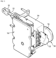
- FIG. 2 illustrates a schematic perspective view of an electronic brake system according to an embodiment.
- the electronic brake system may include a master cylinder 20 which is provided in a hydraulic block 30 and pressurizes and discharges a pressurized medium accommodated therein by an operation of a brake pedal 10, the hydraulic block 30 in which a plurality of flow paths and valves are provided for adjusting a hydraulic pressure therein, a wheel brake 40 coupled to the hydraulic block 30 and provided in each wheel, a hydraulic pressure supply device 50 which is coupled to the hydraulic block 30 and operated by an electrical signal corresponding to a displacement of the brake pedal 10 to generate a hydraulic pressure and supply the generated hydraulic pressure to each of the wheel brakes 40 provided in the respective wheels, a hydraulic control unit 60 that controls a flow of the hydraulic pressure transferred to each of the wheel brakes 40 by the master cylinder 20 or the hydraulic pressure supply device 50, and a control unit (electronic control unit, ECU) 70 that controls the hydraulic pressure supply device 50 and the hydraulic control unit 60 based on hydraulic pressure information and pedal displacement information.
- a master cylinder 20 which is provided in a hydraulic block 30 and pressurizes and
- the master cylinder 20 is connected to the brake pedal 10 and includes a master chamber and a master piston pressurized when the brake pedal 10 is depressed, to generate a hydraulic pressure.
- the master cylinder 20 may include a clevis 21 coupled to the brake pedal 10 and an input shaft 22 coupled to the clevis 21.
- a reservoir for storing oil is coupled to an upper portion of the hydraulic block 30 in which the master cylinder 20 is provided to provide a hydraulic pressure to the master cylinder 20.
- the hydraulic block 30 has a hexahedral shape and may function to transfer the hydraulic pressure to the wheel brake 40 provided in each of the wheels.
- the hydraulic block 30 may have flow paths formed therein to control the hydraulic pressure transferred to the wheel brake 40, and a plurality of valves may be installed therein.
- the master cylinder 20 may be provided inside the hydraulic block 30.
- the hydraulic pressure supply device 50 may include a motor 51, coupled to a side surface of the hydraulic block 30, and a slave cylinder 52 pressurized by a power conversion unit which is coupled to the motor 51 and converts a rotational force into a linear motion.
- the motor 51 may be a three-phase motor.
- the motor 51 is a permanent magnet synchronous motor (PMSM).
- the motor 51 may have a stator and a rotor.
- the power conversion unit may be provided to have a plurality of gears that receive the rotational force from a rotational shaft of the motor 51 and convert the rotational motion into linear motion.
- the power conversion unit may have an assembly structure of a worm and worm wheel gear and a rack and pinion gear to convert the rotational force into the linear motion.
- the slave cylinder 52 is installed inside the hydraulic block 30, separately from the master cylinder 20, and may include a slave piston 52a, which reciprocates by the rotational force of the motor 51 to generate a hydraulic pressure, and a hydraulic chamber 52b pressurized by the slave piston 52a.
- a rack gear may be formed in a portion of the slave piston 52a to linearly move through the power conversion unit.
- the hydraulic pressure supply device 50 may be provided in various manners or structures.
- the hydraulic control unit 60 may control the hydraulic pressure transferred to the wheel brake 40 from the master cylinder 20 or the hydraulic pressure supply device 50.
- the hydraulic control unit 60 may include an electronically open and closed solenoid valve.
- ABS anti-lock braking system
- control unit 70 may close a cut valve provided in a flow path between the master cylinder 20 and the wheel brake 40 to prevent a hydraulic pressure discharged from the master cylinder 20 from being transferred to the wheel brake 40.
- the controller 40 may operate the hydraulic pressure supply device 50 to generate a hydraulic pressure. For example, by moving the slave piston 52a by an operation of the motor 51 of the hydraulic pressure supply device 50, a hydraulic pressure may be generated in the hydraulic chamber 52b. The hydraulic pressure generated by the hydraulic pressure supply device 50 may be supplied to the wheel brake 40 through the hydraulic control unit 60 to generate a braking force on the wheels. In this instance, the control unit 70 may drive the hydraulic pressure supply device 50 and the hydraulic control unit 60 according to a required ABS target pressure, thereby increasing, decreasing or maintaining a pressure of the wheel brake 40 of each of the wheels.
- the electronic brake system has a structure in which the motor 51 and the brake pedal 10 are mounted on the same hydraulic block 30, which enables vibration of the motor 51 to be directly transmitted to the brake pedal 10.
- the electronic brake system may generate vibration corresponding to an ABS operation in the motor 51 through control of the motor, thereby enabling the driver to recognize whether the ABS is operating by a vibration pattern transmitted to the brake pedal 10 and an alarm sound generated by the vibration pattern.
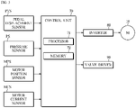
- FIG. 3 illustrates a control block of an electronic brake system according to an embodiment.
- the electronic brake system may include the control unit 70 that performs overall control.
- An inverter 80 and a valve driver 90 may be electrically connected to an output side of the control unit 70.
- a pedal displacement sensor (PTS), a pressure sensor (PS), a motor position sensor (MPS), and a motor current sensor (MCS) may be electrically connected to an input side of the control unit 70.
- the inverter 80 may drive the motor 51.
- the valve driver 90 may drive various types of electromagnetic valves of the electronic brake system.
- the valve driver 90 may drive a solenoid valve of the hydraulic control unit 60.
- the PTS may detect an operation and a displacement of the brake pedal 10.
- the PS may detect a pressure of the wheel brake 40. Also, the PS may detect a hydraulic pressure transferred to the wheel brake 40.
- the MPS may detect a rotation position and rotation speed of the motor 51.
- the MPS may include at least one Hall sensor for detecting a position of a rotor.
- the Hall sensor is an application of a galvanomagnetic effect called a 'Hall effect'.
- the Hall effect refers to a generation of electromotive force (Hall voltage) at both ends of a compound semiconductor when a current flows through the compound semiconductor and a magnetic field is applied at a right angle.
- Hall voltage electromotive force
- the Hall sensor may detect a change in pole of a permanent magnet provided in a rotor using the above principle to identify a position or a speed of the rotor.
- the MCS may detect a current flowing in each phase of the motor 51.
- the MCS may include a first current sensor for detecting a current flowing in any one phase of three phases of the motor 51 and a second current sensor for detecting a current flowing in any one of the remaining two phases.
- Each of the PTS, the PS, the MPS and the MCS may transmit detected information to the control unit 70.
- the control unit 70 may be referred to as an electronic control unit (ECU).
- ECU electronice control unit
- the control unit 70 may include a processor 71 and a memory 72.
- the memory 72 may temporarily store detection data received from the PTS, the PS, the MPS, and the MCS, and also temporarily store a processing result of the detection data by the processor 71.
- the memory 72 may include a volatile memory such as a static random access memory (S-RAM) and dynamic random access memory (D-RAM), and a non-volatile memory such as a flash memory, a read only memory (ROM), an erasable programmable read only memory (EPROM), and the like
- a volatile memory such as a static random access memory (S-RAM) and dynamic random access memory (D-RAM)
- D-RAM dynamic random access memory
- non-volatile memory such as a flash memory, a read only memory (ROM), an erasable programmable read only memory (EPROM), and the like
- the processor 71 may drive the motor 51 through the inverter 80 based on various information detected through the PTS, the PS, the MPS, and the MCS, and drive the hydraulic control unit 60 through the valve driver 90.
- the processor 71 may drive the motor 51 and the hydraulic control unit 60, thereby generating a hydraulic pressure by a movement of the slave piston 52a. Also, the processor 71 may supply the generated hydraulic pressure to the wheel brake 40 provided in each wheel, thereby braking the wheels.
- the processor 71 may determine a target pressure (command pressure) according to a pedal displacement detected through the PTS in a normal braking mode.
- the processor 71 may determine a target pressure (command pressure) according to an ABS situation in an ABS mode.
- the processor 71 may detect a motor position through the MPS.
- the processor 71 may determine the amount of movement of the slave piston 52a from a change in motor position. The amount of movement of the slave piston 52a from an original position to a current position may be determined from the change in motor position.
- the processor 71 may determine a pressure by converting the amount of movement of the slave piston 52a into a pressure value. As the slave piston 52a moves forward, a volume of the hydraulic chamber 52b decreases and a pressure may increase. The processor 71 may convert the pressure from the amount of movement of the slave piston 52a in same volume. The opposite is also possible.
- the processor 71 may determine a pressure of the wheel brake 40 detected through the PS as a circuit pressure.
- the processor 71 may detect a displacement of the brake pedal 10 through the PTS, determine the target pressure based on the detected displacement of the brake pedal 10, set the determined target pressure as a target pressure of the wheel brake 40, detect a pressure of the wheel brake 40 through the PS, and move the slave piston 52a using a rotational force of the motor 51 so that the detected pressure of the wheel brake 40 reaches the set target pressure.
- the processor 71 may switch the normal braking mode to the ABS mode.
- the processor 71 may set a target pressure according to the ABS control situation as a target pressure of the wheel brake 40, detect a pressure of the wheel brake 40 through the PS, and operate the motor 51 and the hydraulic control unit 60 so that the detected pressure of the wheel brake 40 reaches the set target pressure.
- the processor 71 may vibrate the motor 51 by excitation/vibration, thereby transmitting the vibration to the brake pedal 10 to enable the driver to recognize the ABS operation.
- the processor 71 may apply a dithering signal to a current command of the motor 51, thereby inducing vibration of the brake pedal 10 through motor excitation/vibration while minimizing an effect of pressure control, to enable the driver to recognize an ABS operation.
- the driver may feel the vibration of the brake pedal 10 and recognize whether ABS is operating.
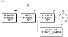
- FIG. 4 illustrates a schematic control block of a controller of an electronic brake system according to an embodiment.
- control unit 70 may include a pressure control unit 100, a speed control unit 110, a current control unit 120, and an excitation current control unit 130.
- the pressure control unit 100 may output a speed command for adjusting a speed of the motor 51 so that an actual pressure of the wheel brake 40 reaches a command pressure.
- the pressure control unit 100 may output the speed command to the speed control unit 110.
- the speed control unit 110 may output a current command for adjusting a current of the motor 51 so that an actual speed of the motor 51 reaches a command speed.
- the speed control unit 110 may output the current command to the current control unit 120.
- the current control unit 120 may output a voltage command for adjusting a voltage of the motor 51 so that an actual current of the motor 51 reaches a command current.
- the current control unit 120 may output the voltage command to the motor 51 side.
- the excitation current control unit 130 may output an excitation current command for exciting the motor 51.
- the excitation current control unit 130 may output the excitation current command to the current control unit 120.
- FIG. 5 illustrates a detailed control block of a controller of an electronic brake system according to an embodiment.
- the pressure control unit 100 may include a pressure controller 101 controlling overall operations of the pressure control unit 100.
- the speed control unit 110 may include a speed controller 111 controlling overall operations of the speed control unit 110.
- the current control unit 120 may include a current controller 121/coordinate converter 122 or the current controller 121 controlling overall operations of the current control unit 120.
- the excitation current control unit 130 may include an excitation current controller 131 controlling overall operations of the excitation current control unit 130.
- the motor 51 may be controlled by the inverter 80.
- the inverter 80 may be controlled by the current controller 121.
- the speed controller 111 may receive a speed command according to a pressure difference between a command pressure and an actual pressure from the pressure controller 101, and provide a current command to the current controller 121.
- the current controller 121 may output a three-phase voltage command to the inverter 80, and the inverter 80 may provide the motor 51 with a three-phase current according to the three-phase voltage command.
- the MPS may be mounted on the motor 51, and the MPS may detect a speed of a rotor of the motor 51. The detected speed of the rotor may be used for feedback-control in the speed controller 111.
- the current controller 121 may receive, from the speed controller 111, a d-axis current command Id ⁇ and a q-axis current command Iq ⁇ , which are current commands Id ⁇ and Iq ⁇ of a synchronous coordinate system, and transmit voltage commands Vd ⁇ and Vq ⁇ of the synchronous coordinate system to the coordinate converter 122.
- the coordinate converter 122 may convert the voltage commands of the synchronous coordinate system into a three-phase voltage command (a-phase, b-phase, and c-phase) and provide to the inverter 80.
- the inverter 80 may provide the motor 51 with a three-phase current through a duty of pulse width modulation (PWM) of a three-phase switching circuit, based on the received three-phase voltage command (a-phase, b-phase, and c-phase).
- PWM pulse width modulation
- the current controller 121 may be implemented as a single current controller by integrating a function of the current controller 121 and a function of the coordinate converter 122. (refer to FIG. 6 )
- FIG. 7 illustrates a connection between an inverter and a motor of an electronic brake system according to an embodiment.
- the inverter 80 may be electrically connected to a vehicle battery B+, which is a direct current (DC) power source, and a DC link capacitor C for smoothing a voltage signal.
- the DC link capacitor C may be connected in parallel to the vehicle battery B+.
- the DC link capacitor C may smooth a DC voltage supplied from the vehicle battery B+.
- the DC voltage smoothed by the DC link capacitor C may be supplied to the inverter 80.
- the inverter 80 may drive the motor 51 by converting the DC voltage into a three-phase alternating current (AC) voltage in a form of pulse having an arbitrary variable frequency through a pulse width modulation (PWM).
- the inverter 80 may include a plurality of power switching devices and a plurality of diodes.
- the inverter 80 may include six power switching devices Q1 to Q6 and six diodes D1 to D6.
- the inverter 80 may turn on or off the power switching devices Q1 to Q6 according to a three-phase voltage command (a-phase, b-phase, and c-phase) provided from the current controller 121, thereby converting the current supplied from the battery B+ from a direct current to an alternating current and supplying to the motor 51.
- a-phase, b-phase, and c-phase a three-phase voltage command
- the voltage of the battery B+ may be boosted by a converter and supplied to the inverter 80.
- Each phase terminal of the motor 51 is connected to the inverter 80.
- the motor 51 may have three coils which are an a-phase coil, a b-phase coil, and a c-phase coil.
- the a-phase coil, the b-phase coil, and the c-phase coil may form a Y configuration.
- an alternating current having a phase difference of 120 degrees may be applied to each coil, thereby rotating a rotation shaft of the motor 51.
- the current controller 121 may apply a voltage command to the inverter 80, so that a measured value of the driving current supplied by the inverter 80 to the motor 51 follows the current command.
- the MCS for detecting the driving current supplied from the inverter 80 to the motor 51 may be provided between the inverter 80 and the motor 51.
- the MCS may measure two or more currents among the three-phase driving currents and the currents may be fed back to the current controller 121.
- the current controller 121 may perform feedback control so that the measured driving current values Id and Iq follow the current commands Id ⁇ and Iq ⁇ received from the speed controller 111.
- the excitation current controller 131 may transmit to the current controller 121 by adding an excitation current command Ie or 0 to the q-axis current command Iq ⁇ . That is, by transmitting the q-axis current command Iq ⁇ together with the excitation current command Ie, the motor 51 may be vibrated by the excitation current command Ie transmitted together with the q-axis current command Iq ⁇ when driving the motor.
- the processor 71 may generate vibration to the brake pedal 10 by exciting the motor 51 and generate an alarm sound that the driver may hear by inducing a vehicle shaking due to the vibration of the motor 51.
- Each of the vibration and the alarm sound may be repeated at a preset pattern.
- the processor 71 may transmit the current command of the motor 51 together with the excitation current command, thereby generating a specific sound pattern through motor excitation/vibration while minimizing an effect of pressure control to enable the driver to recognize whether ABS is operating through the alarm sound.
- FIG. 8 illustrates an excitation current when an ABS is operating, in an electronic brake system according to an embodiment.
- an excitation current command is injected into a q-axis current command Iq ⁇ in an ABS notification ON period, but not injected into the q-axis current command Iq ⁇ in an ABS notification OFF period, so that a driver may reliably recognize an ABS operation and an ABS release in an ABS operation period.
- An excitation current may have a preset amplitude and a preset frequency.
- the excitation current may have a frequency which provides ' ⁇ ' to a basic command current for a brake pedal feeling according to an ABS operation.
- the frequency of the excitation current may be determined in a region that does not overlap an ABS operation frequency.
- the amplitude and a period of the excitation current may vary depending on a capacity and a load size of the motor 51.
- the amplitude of the excitation current is provided so that the amount of load entering is the same as the amount of load being subtracted based on a q-axis current, and thus a slight ripple may occur in a speed of the motor. However, pressure fluctuations may be minimized in terms of pressure.
- a total amplitude value may be assigned from 0 to 100 based on 0, or ⁇ 50 based on 50. Based on an arbitrary reference value, a specific value determined according to the reference value may be assigned as ⁇ .
- an amplitude value may be determined in a + direction based on the q-axis current, and may also be determined in a - direction. That is, an amplitude may be given in a single direction.
- a total excitation duty cycle of an excitation current pattern may be adjusted to minimize the effect on the pressure control.
- a load may be distributed by applying the excitation current pattern at 25 % duty cycle from the total excitation duty cycle.
- a load may be distributed by applying the excitation current pattern at 50 % duty cycle from the total excitation duty cycle.
- At least one of the amplitude or the period of the excitation current may be changed.
- vibration is generated in a motor driving pattern and transmitted to the brake pedal, and thus the driver may recognize whether the ABS is operating.
- the driver may recognize whether the ABS is operating through the alarm sound.
- the excitation current may be periodically repeated in the ABS notification ON period and the ABS notification OFF period during the ABS operation period.
- the excitation current may be discontinuously repeated in the ABS operation period.
- the alarm sound due to the vehicle shaking may be generated together with vibration in the ABS operation period.
- FIG. 9 illustrates another example of excitation current in an electronic brake system according to an embodiment.
- motor vibration and an alarm sound having a specific tone may be generated by varying a vibration period of excitation current in an ABS operation period.
- the excitation current may combine two or more different frequencies, not a single frequency.
- the excitation current may include a first frequency having a first period and a second frequency having a second period.
- the excitation current may continuously repeat the first frequency and the second frequency.
- the excitation current may diversify a pattern of the alarm sound by having the first and second frequencies.
- the motor vibration causes a vehicle shaking according to the two different frequencies, and the vehicle shaking may generate the alarm sound such as a beep sound in which two sounds are repeated. Accordingly, a driver may recognize whether an ABS is operating through the alarm sound together with a brake pedal feeling.
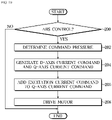
- FIG. 10 illustrates a control method of an electronic brake system according to an embodiment.
- control unit 70 may determine whether ABS control is required (200).
- control unit 70 may determine a command pressure according to an ABS control situation (202).
- the control unit 70 may generate a d-axis current command and a q-axis current command according to the determined command pressure (204).
- the control unit 70 may add an excitation current command to the q-axis current command (206).
- the control unit 70 may drive the motor 51 through the inverter 80 according to the d-axis current command and the q-axis current command to which the excitation current command is added (208). Accordingly, the motor 51 generates vibration by an excitation current added to a command current, and the vibration may be transmitted to the brake pedal 10, thereby generating vibration similar to a kickback phenomenon to the brake pedal 10. Also, due to a change in frequency of excitation current, a vehicle shaking may generate an alarm sound in a form of beep sound. Accordingly, a driver may recognize whether ABS is operating through the vibration of the brake pedal 10 and the alarm sound.
- the excitation current command is added to the q-axis current command
- the excitation current command may also be added to the d-axis current command.
- control unit and/or its constituent components may include at least one processor/microprocessor(s) combined with a computer-readable recording medium storing a computer-readable code/algorithm/software.
- the processor/microprocessor(s) may execute the computer-readable code/algorithm/software stored in the computer-readable recording medium to perform the above-described functions, operations, steps, and the like.
- the aforementioned controller and/or its constituent components may further include a memory implemented as a non-transitory computer-readable recording medium or transitory computer-readable recording medium.
- the memory may be controlled by the aforementioned controller and/or its constituent components and configured to store data, transmitted to or received from the aforementioned controller and/or its constituent components, or data processed or to be processed by the aforementioned controller and/or its constituent components.
- the disclosed embodiment may be implemented as the computer-readable code/algorithm/software in the computer-readable recording medium.
- the computer-readable recording medium may be a non-transitory computer-readable recording medium such as a data storage device capable of storing data readable by the processor/microprocessor(s).
- the computer-readable recording medium may be a hard disk drive (HDD), a solid state drive (SDD), a silicon disk drive (SDD), a read only memory (ROM), a compact disc read only memory (CD-ROM), a magnetic tape, a floppy disk, an optical recording medium, and the like.
Landscapes
- Engineering & Computer Science (AREA)
- Mechanical Engineering (AREA)
- Transportation (AREA)
- Power Engineering (AREA)
- Automation & Control Theory (AREA)
- Human Computer Interaction (AREA)
- Physics & Mathematics (AREA)
- General Physics & Mathematics (AREA)
- Regulating Braking Force (AREA)
Abstract
Description
- The disclosure relates to an electronic brake system that generates a braking force according to an electrical signal corresponding to a displacement of a brake pedal and a control method thereof.
- As part of the preparation for emergency braking, autonomous driving and ongoing demand for eco-friendly technology and safety, the development of a brake-by-wire system that replaces mechanical connections among components of a master cylinder, a booster, an anti-lock braking system (ABS)/electronic stability control (ESC) with electrical and electronic connections is rapidly in progress. In particular, a demand for an integrated electronic brake system that integrates a master cylinder and an actuator into a single block to reduce engine load, reduce weight and allow more design flexibility is increasing.
- Unlike an existing brake system, when ABS is activated, because a direct connection between a master cylinder and a wheel brake is disconnected in the integrated electronic brake system, a driver's brake pedal operation is not directly linked to the wheel brake. Accordingly, a kickback phenomenon where a brake pedal vibration occurs during an ABS operation does not occur, and thus a driver may not recognize whether ABS is operating. Also, since an ABS noise is not loud, the driver may not be aware of whether ABS is operating, causing a difficulty in the driver's defensive driving.
- Therefore, in the integrated electronic brake system, a new method is required for allowing a driver to recognize whether ABS is operating during an ABS operation.
- An aspect of the disclosure provides an electronic brake system and a control method thereof that may notify a driver of whether ABS is operating when ABS is activated.
- According to an aspect of the disclosure, there is provided an electronic brake system including: a master cylinder connected to a brake pedal; a hydraulic pressure supply device including a motor that generates a rotational force and a hydraulic piston movably accommodated in a pressure chamber, and configured to generate a hydraulic pressure by a movement of the hydraulic piston; a hydraulic control unit configured to control a flow of the hydraulic pressure transferred to a wheel cylinder from the hydraulic pressure supply device; a hydraulic block in which the master cylinder, the hydraulic pressure supply device and the hydraulic control unit are integrated; and a controller configured to control the motor and the hydraulic control unit, wherein, during an anti-lock braking system (ABS) operation, the controller is configured to generate vibration in the motor by supplying the motor with an excitation current for exciting the motor to notify a driver of the ABS operation by vibration of the brake pedal.
- The controller is configured to generate vibration simulating a kickback of the brake pedal in the motor in an ABS operation period.
- The controller is configured to periodically repeat an ABS operation notification ON period for which the excitation current is supplied and an ABS operation notification OFF period for which the excitation current is not supplied, in the ABS operation period.
- The controller is configured to supply the motor with an excitation current of a frequency which does not overlap an ABS operation frequency band.
- The controller is configured to generate the vibration in the motor to generate vibration simulating a kickback of the brake pedal in an ABS operation period and generate an alarm sound due to shaking of a vehicle body.
- The controller is configured to supply the motor with an excitation current having a plurality of frequencies different from each other.
- The controller is configured to supply the motor with an excitation current in which a first frequency and a second frequency are continuously repeated, to generate an alarm sound where two sounds are repeated.
- During the ABS operation, the controller is configured to generate the excitation current by adding an excitation current command for generating the excitation current to a q-axis current command among the q-axis current command and a d-axis current command generated according to a target pressure.
- According to another aspect of the disclosure, there is provided a control method of an electronic brake system including a master cylinder connected to a brake pedal; a hydraulic pressure supply device including a motor that generates a rotational force and a hydraulic piston movably accommodated in a pressure chamber, and configured to generate a hydraulic pressure by a movement of the hydraulic piston; a hydraulic control unit configured to control a flow of the hydraulic pressure transferred to a wheel cylinder from the hydraulic pressure supply device; a hydraulic block in which the master cylinder, the hydraulic pressure supply device and the hydraulic control unit are integrated; and a controller configured to control the motor and the hydraulic control unit, the control method including: during an ABS operation, generating vibration in the motor by supplying the motor with an excitation current for exciting the motor to notify a driver of the ABS operation by vibration of the brake pedal.
- Vibration simulating a kickback of the brake pedal is caused to be generated in the motor in an ABS operation period
- An ABS operation notification ON period for which the excitation current is supplied and an ABS operation notification OFF period for which the excitation current is not supplied are periodically repeated in the ABS operation period.
- The vibration is caused to be generated in the motor to generate vibration simulating a kickback of the brake pedal in an ABS operation period and generate an alarm sound due to shaking of a vehicle body.
- The motor is supplied with an excitation current having a plurality of frequencies different from each other.
- The motor is supplied with an excitation current in which a first frequency and a second frequency are continuously repeated, to generate an alarm sound where two sounds are repeated.
- According to an aspect of the disclosure, an electronic brake system and a control method thereof can notify a driver of whether ABS is operating when ABS is activated..
-
-
FIG. 1 illustrates a schematic diagram of an electronic brake system according to an embodiment. -
FIG. 2 illustrates a schematic perspective view of an electronic brake system according to an embodiment. -
FIG. 3 illustrates a control block of an electronic brake system according to an embodiment. -
FIG. 4 illustrates a schematic control block of a controller of an electronic brake system according to an embodiment. -
FIG. 5 illustrates a detailed control block of a controller of an electronic brake system according to an embodiment. -
FIG. 6 illustrates another example of a detailed control block of a controller of an electronic brake system according to an embodiment. -
FIG. 7 illustrates a connection between an inverter and a motor of an electronic brake system according to an embodiment. -
FIG. 8 illustrates an excitation current when an anti-lock braking system (ABS) is operating, in an electronic brake system according to an embodiment. -
FIG. 9 illustrates another example of excitation current in an electronic brake system according to an embodiment. -
FIG. 10 illustrates a control method of an electronic brake system according to an embodiment. - Like reference numerals throughout the specification denote like elements. Also, this specification does not describe all the elements according to embodiments of the disclosure, and descriptions well-known in the art to which the disclosure pertains or overlapped portions are omitted. The terms such as "-part", "~member", "-module", "~block", and the like may refer to at least one process processed by at least one hardware or software. According to embodiments, a plurality of "-part", "~member", "~module", "-block" may be embodied as a single element, or a single of "-part", "~member", "~module", "-block" may include a plurality of elements.
- It will be understood that when an element is referred to as being "connected" to another element, it can be directly or indirectly connected to the other element, wherein the indirect connection includes connection via a wireless communication network.
- It will be understood that the term "include" when used in this specification, specifies the presence of stated elements, but do not preclude the presence or addition of one or more other elements.
- It will be understood that when it is stated in this specification that a member is located "on" another member, not only a member may be in contact with another member, but also still another member may be present between the two members.
- It will be understood that, although the terms first, second, etc. may be used herein to describe various elements, these elements should not be limited by these terms. It is to be understood that the singular forms are intended to include the plural forms as well, unless the context clearly dictates otherwise.
- Reference numerals used for method steps are just used for convenience of explanation, but not to limit an order of the steps. Thus, unless the context clearly dictates otherwise, the written order may be practiced otherwise.
-
FIG. 1 illustrates a schematic diagram of an electronic brake system according to an embodiment.FIG. 2 illustrates a schematic perspective view of an electronic brake system according to an embodiment. - Referring to
FIGS. 1 and2 , the electronic brake system may include amaster cylinder 20 which is provided in ahydraulic block 30 and pressurizes and discharges a pressurized medium accommodated therein by an operation of abrake pedal 10, thehydraulic block 30 in which a plurality of flow paths and valves are provided for adjusting a hydraulic pressure therein, awheel brake 40 coupled to thehydraulic block 30 and provided in each wheel, a hydraulicpressure supply device 50 which is coupled to thehydraulic block 30 and operated by an electrical signal corresponding to a displacement of thebrake pedal 10 to generate a hydraulic pressure and supply the generated hydraulic pressure to each of thewheel brakes 40 provided in the respective wheels, ahydraulic control unit 60 that controls a flow of the hydraulic pressure transferred to each of thewheel brakes 40 by themaster cylinder 20 or the hydraulicpressure supply device 50, and a control unit (electronic control unit, ECU) 70 that controls the hydraulicpressure supply device 50 and thehydraulic control unit 60 based on hydraulic pressure information and pedal displacement information. - The
master cylinder 20 is connected to thebrake pedal 10 and includes a master chamber and a master piston pressurized when thebrake pedal 10 is depressed, to generate a hydraulic pressure. - The
master cylinder 20 may include aclevis 21 coupled to thebrake pedal 10 and aninput shaft 22 coupled to theclevis 21. - A reservoir for storing oil is coupled to an upper portion of the
hydraulic block 30 in which themaster cylinder 20 is provided to provide a hydraulic pressure to themaster cylinder 20. - The
hydraulic block 30 has a hexahedral shape and may function to transfer the hydraulic pressure to thewheel brake 40 provided in each of the wheels. - The
hydraulic block 30 may have flow paths formed therein to control the hydraulic pressure transferred to thewheel brake 40, and a plurality of valves may be installed therein. - The
master cylinder 20 may be provided inside thehydraulic block 30. - The hydraulic
pressure supply device 50 may include amotor 51, coupled to a side surface of thehydraulic block 30, and aslave cylinder 52 pressurized by a power conversion unit which is coupled to themotor 51 and converts a rotational force into a linear motion. - The
motor 51 may be a three-phase motor. For example, themotor 51 is a permanent magnet synchronous motor (PMSM). Themotor 51 may have a stator and a rotor. The power conversion unit may be provided to have a plurality of gears that receive the rotational force from a rotational shaft of themotor 51 and convert the rotational motion into linear motion. For example, the power conversion unit may have an assembly structure of a worm and worm wheel gear and a rack and pinion gear to convert the rotational force into the linear motion. - The
slave cylinder 52 is installed inside thehydraulic block 30, separately from themaster cylinder 20, and may include aslave piston 52a, which reciprocates by the rotational force of themotor 51 to generate a hydraulic pressure, and ahydraulic chamber 52b pressurized by theslave piston 52a. In this instance, a rack gear may be formed in a portion of theslave piston 52a to linearly move through the power conversion unit. - The hydraulic
pressure supply device 50 may be provided in various manners or structures. - The
hydraulic control unit 60 may control the hydraulic pressure transferred to thewheel brake 40 from themaster cylinder 20 or the hydraulicpressure supply device 50. - The
hydraulic control unit 60 may include an electronically open and closed solenoid valve. - Hereinafter, an anti-lock braking system (ABS) control operation of the electronic brake system including the above-described constituent components is described.
- During an ABS operation, the
control unit 70 may close a cut valve provided in a flow path between themaster cylinder 20 and thewheel brake 40 to prevent a hydraulic pressure discharged from themaster cylinder 20 from being transferred to thewheel brake 40. - Also, the
controller 40 may operate the hydraulicpressure supply device 50 to generate a hydraulic pressure. For example, by moving theslave piston 52a by an operation of themotor 51 of the hydraulicpressure supply device 50, a hydraulic pressure may be generated in thehydraulic chamber 52b. The hydraulic pressure generated by the hydraulicpressure supply device 50 may be supplied to thewheel brake 40 through thehydraulic control unit 60 to generate a braking force on the wheels. In this instance, thecontrol unit 70 may drive the hydraulicpressure supply device 50 and thehydraulic control unit 60 according to a required ABS target pressure, thereby increasing, decreasing or maintaining a pressure of thewheel brake 40 of each of the wheels. - As described above, in the electronic brake system having the above constituent components, because a direct connection between the
master cylinder 20 and thewheel brake 40 is disconnected during an ABS operation, a driver's brake pedal operation is not directly linked to thewheel brake 40. Accordingly, a kickback phenomenon where vibration occurs in thebrake pedal 10 during an ABS operation does not occur. In addition, an ABS noise is not loud, and thus a driver may not recognize whether an ABS is operating. - Therefore, a new method for enabling a driver to recognize whether an ABS is operating is required.
- The electronic brake system according to an embodiment has a structure in which the
motor 51 and thebrake pedal 10 are mounted on the samehydraulic block 30, which enables vibration of themotor 51 to be directly transmitted to thebrake pedal 10. - Accordingly, the electronic brake system according to an embodiment may generate vibration corresponding to an ABS operation in the
motor 51 through control of the motor, thereby enabling the driver to recognize whether the ABS is operating by a vibration pattern transmitted to thebrake pedal 10 and an alarm sound generated by the vibration pattern. -
FIG. 3 illustrates a control block of an electronic brake system according to an embodiment. - Referring to
FIG. 3 , the electronic brake system may include thecontrol unit 70 that performs overall control. - An
inverter 80 and avalve driver 90 may be electrically connected to an output side of thecontrol unit 70. - A pedal displacement sensor (PTS), a pressure sensor (PS), a motor position sensor (MPS), and a motor current sensor (MCS) may be electrically connected to an input side of the
control unit 70. - The
inverter 80 may drive themotor 51. - The
valve driver 90 may drive various types of electromagnetic valves of the electronic brake system. - The
valve driver 90 may drive a solenoid valve of thehydraulic control unit 60. - The PTS may detect an operation and a displacement of the
brake pedal 10. - The PS may detect a pressure of the
wheel brake 40. Also, the PS may detect a hydraulic pressure transferred to thewheel brake 40. - The MPS may detect a rotation position and rotation speed of the
motor 51. The MPS may include at least one Hall sensor for detecting a position of a rotor. The Hall sensor is an application of a galvanomagnetic effect called a 'Hall effect'. The Hall effect refers to a generation of electromotive force (Hall voltage) at both ends of a compound semiconductor when a current flows through the compound semiconductor and a magnetic field is applied at a right angle. When measuring a Hall voltage using the above phenomenon, whether an applied magnetic field is N-pole or S-pole may be identified. The Hall sensor may detect a change in pole of a permanent magnet provided in a rotor using the above principle to identify a position or a speed of the rotor. - The MCS may detect a current flowing in each phase of the
motor 51. For example, the MCS may include a first current sensor for detecting a current flowing in any one phase of three phases of themotor 51 and a second current sensor for detecting a current flowing in any one of the remaining two phases. - Each of the PTS, the PS, the MPS and the MCS may transmit detected information to the
control unit 70. - The
control unit 70 may be referred to as an electronic control unit (ECU). - The
control unit 70 may include aprocessor 71 and amemory 72. - The
memory 72 may temporarily store detection data received from the PTS, the PS, the MPS, and the MCS, and also temporarily store a processing result of the detection data by theprocessor 71. - The
memory 72 may include a volatile memory such as a static random access memory (S-RAM) and dynamic random access memory (D-RAM), and a non-volatile memory such as a flash memory, a read only memory (ROM), an erasable programmable read only memory (EPROM), and the like - The
processor 71 may drive themotor 51 through theinverter 80 based on various information detected through the PTS, the PS, the MPS, and the MCS, and drive thehydraulic control unit 60 through thevalve driver 90. - The
processor 71 may drive themotor 51 and thehydraulic control unit 60, thereby generating a hydraulic pressure by a movement of theslave piston 52a. Also, theprocessor 71 may supply the generated hydraulic pressure to thewheel brake 40 provided in each wheel, thereby braking the wheels. - The
processor 71 may determine a target pressure (command pressure) according to a pedal displacement detected through the PTS in a normal braking mode. - The
processor 71 may determine a target pressure (command pressure) according to an ABS situation in an ABS mode. - The
processor 71 may detect a motor position through the MPS. - The
processor 71 may determine the amount of movement of theslave piston 52a from a change in motor position. The amount of movement of theslave piston 52a from an original position to a current position may be determined from the change in motor position. - The
processor 71 may determine a pressure by converting the amount of movement of theslave piston 52a into a pressure value. As theslave piston 52a moves forward, a volume of thehydraulic chamber 52b decreases and a pressure may increase. Theprocessor 71 may convert the pressure from the amount of movement of theslave piston 52a in same volume. The opposite is also possible. - The
processor 71 may determine a pressure of thewheel brake 40 detected through the PS as a circuit pressure. - In order to generate a hydraulic pressure, in the normal braking mode, the
processor 71 may detect a displacement of thebrake pedal 10 through the PTS, determine the target pressure based on the detected displacement of thebrake pedal 10, set the determined target pressure as a target pressure of thewheel brake 40, detect a pressure of thewheel brake 40 through the PS, and move theslave piston 52a using a rotational force of themotor 51 so that the detected pressure of thewheel brake 40 reaches the set target pressure. - When an ABS control situation occurs in the normal braking mode, the
processor 71 may switch the normal braking mode to the ABS mode. - In the ABS mode, the
processor 71 may set a target pressure according to the ABS control situation as a target pressure of thewheel brake 40, detect a pressure of thewheel brake 40 through the PS, and operate themotor 51 and thehydraulic control unit 60 so that the detected pressure of thewheel brake 40 reaches the set target pressure. - In the ABS mode, the
processor 71 may vibrate themotor 51 by excitation/vibration, thereby transmitting the vibration to thebrake pedal 10 to enable the driver to recognize the ABS operation. - In the ABS mode, when driving the
motor 51 to generate a hydraulic pressure, theprocessor 71 may apply a dithering signal to a current command of themotor 51, thereby inducing vibration of thebrake pedal 10 through motor excitation/vibration while minimizing an effect of pressure control, to enable the driver to recognize an ABS operation. - When the
motor 51 is excited in the ABS mode, the vibration in themotor 51 is transmitted to thebrake pedal 10 coupled to the samehydraulic block 30 as themotor 51, and thus vibration simulating a kickback may be generated in thebrake pedal 10. - The driver may feel the vibration of the
brake pedal 10 and recognize whether ABS is operating. -
FIG. 4 illustrates a schematic control block of a controller of an electronic brake system according to an embodiment. - Referring to
FIG. 4 , thecontrol unit 70 may include apressure control unit 100, aspeed control unit 110, acurrent control unit 120, and an excitationcurrent control unit 130. - The
pressure control unit 100 may output a speed command for adjusting a speed of themotor 51 so that an actual pressure of thewheel brake 40 reaches a command pressure. - The
pressure control unit 100 may output the speed command to thespeed control unit 110. - The
speed control unit 110 may output a current command for adjusting a current of themotor 51 so that an actual speed of themotor 51 reaches a command speed. - The
speed control unit 110 may output the current command to thecurrent control unit 120. - The
current control unit 120 may output a voltage command for adjusting a voltage of themotor 51 so that an actual current of themotor 51 reaches a command current. - The
current control unit 120 may output the voltage command to themotor 51 side. - The excitation
current control unit 130 may output an excitation current command for exciting themotor 51. - The excitation
current control unit 130 may output the excitation current command to thecurrent control unit 120. -
FIG. 5 illustrates a detailed control block of a controller of an electronic brake system according to an embodiment. - Referring to
FIG. 5 , thepressure control unit 100 may include apressure controller 101 controlling overall operations of thepressure control unit 100. Thespeed control unit 110 may include aspeed controller 111 controlling overall operations of thespeed control unit 110. Thecurrent control unit 120 may include acurrent controller 121/coordinateconverter 122 or thecurrent controller 121 controlling overall operations of thecurrent control unit 120. The excitationcurrent control unit 130 may include an excitationcurrent controller 131 controlling overall operations of the excitationcurrent control unit 130. - The
motor 51 may be controlled by theinverter 80. - The
inverter 80 may be controlled by thecurrent controller 121. - The
speed controller 111 may receive a speed command according to a pressure difference between a command pressure and an actual pressure from thepressure controller 101, and provide a current command to thecurrent controller 121. - The
current controller 121 may output a three-phase voltage command to theinverter 80, and theinverter 80 may provide themotor 51 with a three-phase current according to the three-phase voltage command. - The MPS may be mounted on the
motor 51, and the MPS may detect a speed of a rotor of themotor 51. The detected speed of the rotor may be used for feedback-control in thespeed controller 111. - Specifically, the
current controller 121 may receive, from thespeed controller 111, a d-axis current command Id∗ and a q-axis current command Iq∗, which are current commands Id∗ and Iq∗ of a synchronous coordinate system, and transmit voltage commands Vd∗ and Vq∗ of the synchronous coordinate system to the coordinateconverter 122. The coordinateconverter 122 may convert the voltage commands of the synchronous coordinate system into a three-phase voltage command (a-phase, b-phase, and c-phase) and provide to theinverter 80. Theinverter 80 may provide themotor 51 with a three-phase current through a duty of pulse width modulation (PWM) of a three-phase switching circuit, based on the received three-phase voltage command (a-phase, b-phase, and c-phase). - The
current controller 121 may be implemented as a single current controller by integrating a function of thecurrent controller 121 and a function of the coordinateconverter 122. (refer toFIG. 6 ) -
FIG. 7 illustrates a connection between an inverter and a motor of an electronic brake system according to an embodiment. - Referring to
FIG. 7 , theinverter 80 may be electrically connected to a vehicle battery B+, which is a direct current (DC) power source, and a DC link capacitor C for smoothing a voltage signal. The DC link capacitor C may be connected in parallel to the vehicle battery B+. The DC link capacitor C may smooth a DC voltage supplied from the vehicle battery B+. The DC voltage smoothed by the DC link capacitor C may be supplied to theinverter 80. - The
inverter 80 may drive themotor 51 by converting the DC voltage into a three-phase alternating current (AC) voltage in a form of pulse having an arbitrary variable frequency through a pulse width modulation (PWM). Theinverter 80 may include a plurality of power switching devices and a plurality of diodes. For example, theinverter 80 may include six power switching devices Q1 to Q6 and six diodes D1 to D6. - The
inverter 80 may turn on or off the power switching devices Q1 to Q6 according to a three-phase voltage command (a-phase, b-phase, and c-phase) provided from thecurrent controller 121, thereby converting the current supplied from the battery B+ from a direct current to an alternating current and supplying to themotor 51. In this instance, the voltage of the battery B+ may be boosted by a converter and supplied to theinverter 80. - Each phase terminal of the
motor 51 is connected to theinverter 80. - The
motor 51 may have three coils which are an a-phase coil, a b-phase coil, and a c-phase coil. For example, the a-phase coil, the b-phase coil, and the c-phase coil may form a Y configuration. In themotor 51, an alternating current having a phase difference of 120 degrees may be applied to each coil, thereby rotating a rotation shaft of themotor 51. - Referring again to
FIGS. 5 and6 , thecurrent controller 121 may apply a voltage command to theinverter 80, so that a measured value of the driving current supplied by theinverter 80 to themotor 51 follows the current command. The MCS for detecting the driving current supplied from theinverter 80 to themotor 51 may be provided between theinverter 80 and themotor 51. The MCS may measure two or more currents among the three-phase driving currents and the currents may be fed back to thecurrent controller 121. Thecurrent controller 121 may perform feedback control so that the measured driving current values Id and Iq follow the current commands Id∗ and Iq∗ received from thespeed controller 111. - Meanwhile, when transmitting the q-axis current command Iq∗ from the
speed controller 111 to thecurrent controller 121, the excitationcurrent controller 131 may transmit to thecurrent controller 121 by adding an excitation current command Ie or 0 to the q-axis current command Iq∗. That is, by transmitting the q-axis current command Iq∗ together with the excitation current command Ie, themotor 51 may be vibrated by the excitation current command Ie transmitted together with the q-axis current command Iq∗ when driving the motor. - Referring again to
FIG. 3 , in order for the driver to recognize an ABS operation when the ABS mode is on, theprocessor 71 may generate vibration to thebrake pedal 10 by exciting themotor 51 and generate an alarm sound that the driver may hear by inducing a vehicle shaking due to the vibration of themotor 51. Each of the vibration and the alarm sound may be repeated at a preset pattern. - When driving the
motor 51 to generate a hydraulic pressure in the ABS mode, theprocessor 71 may transmit the current command of themotor 51 together with the excitation current command, thereby generating a specific sound pattern through motor excitation/vibration while minimizing an effect of pressure control to enable the driver to recognize whether ABS is operating through the alarm sound. -
FIG. 8 illustrates an excitation current when an ABS is operating, in an electronic brake system according to an embodiment. - Referring to
FIG. 8 , an excitation current command is injected into a q-axis current command Iq∗ in an ABS notification ON period, but not injected into the q-axis current command Iq∗ in an ABS notification OFF period, so that a driver may reliably recognize an ABS operation and an ABS release in an ABS operation period. - An excitation current may have a preset amplitude and a preset frequency.
- The excitation current may have a frequency which provides '±' to a basic command current for a brake pedal feeling according to an ABS operation.
- The frequency of the excitation current may be determined in a region that does not overlap an ABS operation frequency.
- The amplitude and a period of the excitation current may vary depending on a capacity and a load size of the
motor 51. - The amplitude of the excitation current is provided so that the amount of load entering is the same as the amount of load being subtracted based on a q-axis current, and thus a slight ripple may occur in a speed of the motor. However, pressure fluctuations may be minimized in terms of pressure.
- With respect to the amplitude of the excitation current, a total amplitude value may be assigned from 0 to 100 based on 0, or ±50 based on 50. Based on an arbitrary reference value, a specific value determined according to the reference value may be assigned as ±.
- For reference, for the amplitude of the excitation current, an amplitude value may be determined in a + direction based on the q-axis current, and may also be determined in a - direction. That is, an amplitude may be given in a single direction.
- In addition, a total excitation duty cycle of an excitation current pattern may be adjusted to minimize the effect on the pressure control.
- For example, a load may be distributed by applying the excitation current pattern at 25 % duty cycle from the total excitation duty cycle.
- Also, a load may be distributed by applying the excitation current pattern at 50 % duty cycle from the total excitation duty cycle.
- As such, at least one of the amplitude or the period of the excitation current may be changed.
- As described above, during the ABS operation, by additionally applying the excitation current command to a load current command, vibration is generated in a motor driving pattern and transmitted to the brake pedal, and thus the driver may recognize whether the ABS is operating.
- As such, in the ABS mode, by inducing a specific alarm sound through motor excitation/vibration while minimizing an effect of pressure control, the driver may recognize whether the ABS is operating through the alarm sound.
- The excitation current may be periodically repeated in the ABS notification ON period and the ABS notification OFF period during the ABS operation period.
- The excitation current may be discontinuously repeated in the ABS operation period. In this case, the alarm sound due to the vehicle shaking may be generated together with vibration in the ABS operation period.
-
FIG. 9 illustrates another example of excitation current in an electronic brake system according to an embodiment. - Referring to
FIG. 9 , motor vibration and an alarm sound having a specific tone may be generated by varying a vibration period of excitation current in an ABS operation period. - In the ABS operation period, the excitation current may combine two or more different frequencies, not a single frequency.
- For example, the excitation current may include a first frequency having a first period and a second frequency having a second period.
- The excitation current may continuously repeat the first frequency and the second frequency.
- The excitation current may diversify a pattern of the alarm sound by having the first and second frequencies. The motor vibration causes a vehicle shaking according to the two different frequencies, and the vehicle shaking may generate the alarm sound such as a beep sound in which two sounds are repeated. Accordingly, a driver may recognize whether an ABS is operating through the alarm sound together with a brake pedal feeling.
-
FIG. 10 illustrates a control method of an electronic brake system according to an embodiment. - Referring to
FIG. 10 , first, thecontrol unit 70 may determine whether ABS control is required (200). - When it is determined that the ABS control is required as a result of the determination in
operation 200, thecontrol unit 70 may determine a command pressure according to an ABS control situation (202). - The
control unit 70 may generate a d-axis current command and a q-axis current command according to the determined command pressure (204). - The
control unit 70 may add an excitation current command to the q-axis current command (206). - The
control unit 70 may drive themotor 51 through theinverter 80 according to the d-axis current command and the q-axis current command to which the excitation current command is added (208). Accordingly, themotor 51 generates vibration by an excitation current added to a command current, and the vibration may be transmitted to thebrake pedal 10, thereby generating vibration similar to a kickback phenomenon to thebrake pedal 10. Also, due to a change in frequency of excitation current, a vehicle shaking may generate an alarm sound in a form of beep sound. Accordingly, a driver may recognize whether ABS is operating through the vibration of thebrake pedal 10 and the alarm sound. - Although it is described in the above-described embodiment that the excitation current command is added to the q-axis current command, the excitation current command may also be added to the d-axis current command.
- Meanwhile, the aforementioned control unit and/or its constituent components may include at least one processor/microprocessor(s) combined with a computer-readable recording medium storing a computer-readable code/algorithm/software. The processor/microprocessor(s) may execute the computer-readable code/algorithm/software stored in the computer-readable recording medium to perform the above-described functions, operations, steps, and the like.
- The aforementioned controller and/or its constituent components may further include a memory implemented as a non-transitory computer-readable recording medium or transitory computer-readable recording medium. The memory may be controlled by the aforementioned controller and/or its constituent components and configured to store data, transmitted to or received from the aforementioned controller and/or its constituent components, or data processed or to be processed by the aforementioned controller and/or its constituent components.
- The disclosed embodiment may be implemented as the computer-readable code/algorithm/software in the computer-readable recording medium. The computer-readable recording medium may be a non-transitory computer-readable recording medium such as a data storage device capable of storing data readable by the processor/microprocessor(s). For example, the computer-readable recording medium may be a hard disk drive (HDD), a solid state drive (SDD), a silicon disk drive (SDD), a read only memory (ROM), a compact disc read only memory (CD-ROM), a magnetic tape, a floppy disk, an optical recording medium, and the like.
Claims (14)
- An electronic brake system, comprising:a master cylinder connected to a brake pedal;a hydraulic pressure supply device comprising a motor that generates a rotational force and a hydraulic piston movably accommodated in a pressure chamber, and configured to generate a hydraulic pressure by a movement of the hydraulic piston;a hydraulic control unit configured to control a flow of the hydraulic pressure transferred to a wheel cylinder from the hydraulic pressure supply device;a hydraulic block in which the master cylinder, the hydraulic pressure supply device and the hydraulic control unit are integrated; anda controller configured to control the motor and the hydraulic control unit, wherein, during an anti-lock braking system (ABS) operation, the controller is configured to generate vibration in the motor by supplying the motor with an excitation current for exciting the motor to notify a driver of the ABS operation by vibration of the brake pedal.
- The electronic brake system of claim 1, wherein the controller is configured to generate vibration simulating a kickback of the brake pedal in the motor in an ABS operation period.
- The electronic brake system of claim 2, wherein the controller is configured to periodically repeat an ABS operation notification ON period for which the excitation current is supplied and an ABS operation notification OFF period for which the excitation current is not supplied, in the ABS operation period.
- The electronic brake system of claim 1, wherein the controller is configured to supply the motor with an excitation current of a frequency which does not overlap an ABS operation frequency band.
- The electronic brake system of claim 1, wherein the controller is configured to generate the vibration in the motor to generate vibration simulating a kickback of the brake pedal in an ABS operation period and generate an alarm sound due to shaking of a vehicle body.
- The electronic brake system of claim 5, wherein the controller is configured to supply the motor with an excitation current having a plurality of frequencies different from each other.
- The electronic brake system of claim 6, wherein the controller is configured to supply the motor with an excitation current in which a first frequency and a second frequency are continuously repeated, to generate an alarm sound where two sounds are repeated.
- The electronic brake system of claim 1, wherein, during the ABS operation, the controller is configured to generate the excitation current by adding an excitation current command for generating the excitation current to a q-axis current command among the q-axis current command and a d-axis current command generated according to a target pressure.
- A control method of an electronic brake system comprising a master cylinder connected to a brake pedal; a hydraulic pressure supply device comprising a motor that generates a rotational force and a hydraulic piston movably accommodated in a pressure chamber, and configured to generate a hydraulic pressure by a movement of the hydraulic piston; a hydraulic control unit configured to control a flow of the hydraulic pressure transferred to a wheel cylinder from the hydraulic pressure supply device; a hydraulic block in which the master cylinder, the hydraulic pressure supply device and the hydraulic control unit are integrated; and a controller configured to control the motor and the hydraulic control unit, the control method comprising:
during an ABS operation, generating vibration in the motor by supplying the motor with an excitation current for exciting the motor to notify a driver of the ABS operation by vibration of the brake pedal. - The control method of claim 9, wherein vibration simulating a kickback of the brake pedal is caused to be generated in the motor in an ABS operation period.
- The control method of claim 10, wherein an ABS operation notification ON period for which the excitation current is supplied and an ABS operation notification OFF period for which the excitation current is not supplied are periodically repeated in the ABS operation period.
- The control method of claim 9, wherein the vibration is caused to be generated in the motor to generate vibration simulating a kickback of the brake pedal in an ABS operation period and generate an alarm sound due to shaking of a vehicle body.
- The control method of claim 12, wherein the motor is supplied with an excitation current having a plurality of frequencies different from each other.
- The control method of claim 13, wherein the motor is supplied with an excitation current in which a first frequency and a second frequency are continuously repeated, to generate an alarm sound where two sounds are repeated.
Applications Claiming Priority (2)
| Application Number | Priority Date | Filing Date | Title |
|---|---|---|---|
| KR20200009190 | 2020-01-23 | ||
| PCT/KR2021/000905 WO2021150058A1 (en) | 2020-01-23 | 2021-01-22 | Electronic brake system and control method therefor |
Publications (3)
| Publication Number | Publication Date |
|---|---|
| EP4079590A1 true EP4079590A1 (en) | 2022-10-26 |
| EP4079590A4 EP4079590A4 (en) | 2023-07-26 |
| EP4079590B1 EP4079590B1 (en) | 2024-07-10 |
Family
ID=76992677
Family Applications (1)
| Application Number | Title | Priority Date | Filing Date |
|---|---|---|---|
| EP21743675.7A Active EP4079590B1 (en) | 2020-01-23 | 2021-01-22 | Electronic brake system and control method therefor |
Country Status (6)
| Country | Link |
|---|---|
| US (1) | US12623639B2 (en) |
| EP (1) | EP4079590B1 (en) |
| KR (1) | KR102727578B1 (en) |
| CN (1) | CN114981137B (en) |
| PL (1) | PL4079590T3 (en) |
| WO (1) | WO2021150058A1 (en) |
Families Citing this family (2)
| Publication number | Priority date | Publication date | Assignee | Title |
|---|---|---|---|---|
| DE102021202168B3 (en) * | 2021-03-05 | 2022-04-28 | Zf Friedrichshafen Ag | Method of monitoring a vehicle |
| KR20240048765A (en) * | 2022-10-07 | 2024-04-16 | 현대자동차주식회사 | Judder identification device, and Vehicle having the same |
Family Cites Families (24)
| Publication number | Priority date | Publication date | Assignee | Title |
|---|---|---|---|---|
| JP2773108B2 (en) * | 1996-06-20 | 1998-07-09 | 豊田通商株式会社 | Driving simulator device |
| JP3641953B2 (en) * | 1997-11-25 | 2005-04-27 | 富士電機機器制御株式会社 | Control method of permanent magnet type synchronous motor |
| DE19753786A1 (en) | 1997-12-04 | 1999-06-10 | Itt Mfg Enterprises Inc | Braking system for motor vehicle |
| DE10040511A1 (en) * | 2000-03-09 | 2001-09-20 | Continental Teves Ag & Co Ohg | Automobile safety-critical measurement detection system has at least 2 independent measuring channels provided with independent sensors |
| JP2004090899A (en) * | 2002-09-04 | 2004-03-25 | Advics:Kk | Brake alarm device for vehicle |
| DE102007045292B4 (en) * | 2007-09-22 | 2016-04-28 | Volkswagen Ag | Vehicle brake system with an electromechanical brake booster and a slip control system |
| KR101400539B1 (en) * | 2008-01-23 | 2014-05-28 | 엘지전자 주식회사 | Motor and controlling system for the motor, controlling method for the motor, and waching machine |
| JP2009303435A (en) * | 2008-06-17 | 2009-12-24 | Sanyo Electric Co Ltd | Motor controller |
| DE102009033499A1 (en) * | 2008-07-18 | 2010-01-21 | Continental Teves Ag & Co. Ohg | Brake system for motor vehicles |
| JP5049939B2 (en) * | 2008-10-07 | 2012-10-17 | 本田技研工業株式会社 | Brake device for vehicle |
| JP5228996B2 (en) * | 2009-02-27 | 2013-07-03 | 日産自動車株式会社 | Vibration suppression control device for electric vehicle |
| KR101126847B1 (en) * | 2009-12-04 | 2012-03-23 | 현대자동차주식회사 | Operation mode embodiment pendant type Adjustment Pedal Apparatus |
| JP2013123972A (en) * | 2011-12-14 | 2013-06-24 | Nissan Motor Co Ltd | Vehicle braking force control device |
| JP5856465B2 (en) * | 2011-12-16 | 2016-02-09 | トヨタ自動車株式会社 | vehicle |
| DE102013217257A1 (en) * | 2012-09-03 | 2014-04-03 | Robert Bosch Gmbh | Hydraulic unit of a vehicle brake system with a motor shaft bearing |
| JP6131131B2 (en) * | 2013-07-04 | 2017-05-17 | 本田技研工業株式会社 | Vehicle braking system |
| KR101729940B1 (en) * | 2013-07-25 | 2017-04-25 | 주식회사 만도 | Pump unit of electronic control brake system |
| KR102016381B1 (en) * | 2014-12-30 | 2019-10-21 | 주식회사 만도 | Electric brake system |
| ITUB20156916A1 (en) * | 2015-12-09 | 2017-06-09 | Freni Brembo Spa | BRAKING SYSTEM FOR BRAKE BY WIRE TYPE VEHICLES EQUIPPED WITH HYDRAULIC FEEDBACK SIMULATOR, AND METHOD OF IMPLEMENTATION OF A BRAKE SYSTEM FOR VEHICLES |
| US10870418B2 (en) * | 2017-02-15 | 2020-12-22 | Mando Corporation | Electronic brake system and control method thereof |
| KR102515675B1 (en) * | 2017-02-15 | 2023-03-29 | 에이치엘만도 주식회사 | Electronic brake system and control method thereof |
| DE102017212366A1 (en) * | 2017-07-19 | 2019-01-24 | Bayerische Motoren Werke Aktiengesellschaft | Driver assistance system, means of locomotion and method for assisting a user in the operation of a brake system |
| JP6936157B2 (en) * | 2018-01-26 | 2021-09-15 | 株式会社シマノ | Braking control device and braking device equipped with this |
| JP6901650B2 (en) * | 2018-05-16 | 2021-07-14 | 相原 雅彦 | Electric vehicle |
-
2021
- 2021-01-22 EP EP21743675.7A patent/EP4079590B1/en active Active
- 2021-01-22 CN CN202180010412.1A patent/CN114981137B/en active Active
- 2021-01-22 US US17/794,615 patent/US12623639B2/en active Active
- 2021-01-22 PL PL21743675.7T patent/PL4079590T3/en unknown
- 2021-01-22 KR KR1020227026025A patent/KR102727578B1/en active Active
- 2021-01-22 WO PCT/KR2021/000905 patent/WO2021150058A1/en not_active Ceased
Also Published As
| Publication number | Publication date |
|---|---|
| PL4079590T3 (en) | 2024-12-16 |
| KR20220116310A (en) | 2022-08-22 |
| WO2021150058A1 (en) | 2021-07-29 |
| EP4079590B1 (en) | 2024-07-10 |
| US12623639B2 (en) | 2026-05-12 |
| CN114981137B (en) | 2023-12-22 |
| KR102727578B1 (en) | 2024-11-07 |
| EP4079590A4 (en) | 2023-07-26 |
| CN114981137A (en) | 2022-08-30 |
| US20230061412A1 (en) | 2023-03-02 |
Similar Documents
| Publication | Publication Date | Title |
|---|---|---|
| US9531305B2 (en) | Inverter apparatus | |
| JP4620709B2 (en) | In-vehicle actuator system | |
| US20070216218A1 (en) | Brake by wire type brake system | |
| CN103619676A (en) | Braking System | |
| EP4079590B1 (en) | Electronic brake system and control method therefor | |
| US11001242B2 (en) | Braking control device for vehicle | |
| US20150372629A1 (en) | System, method and apparatus of sensor-less field oriented control for permanent magnet motor | |
| US7818111B2 (en) | Motor control apparatus and motor control method | |
| CN106416050A (en) | Method for controlling a braking system | |
| EP2345147B1 (en) | System and method for controlling power balance in an electrical/mechanical system | |
| JP6508112B2 (en) | Vehicle braking control device | |
| KR20150124394A (en) | Motor driving system | |
| Hao et al. | Electromechanical regenerative actuator with fault-tolerance capability for automotive chassis applications | |
| CN109661335A (en) | The brake control of vehicle | |
| US10562399B2 (en) | Motor control device of vehicle | |
| JP2021035220A (en) | Motor drive device | |
| JP2002013566A (en) | Electric disc brake device | |
| KR20190028008A (en) | Motor controlling device for vehicle and control method thereof | |
| JP6707981B2 (en) | Vehicle braking control device | |
| KR102330383B1 (en) | Electric Brake Booster System for Vehicles | |
| JP6634868B2 (en) | Vehicle motor control device | |
| JP6855708B2 (en) | Vehicle braking control device | |
| US20240400012A1 (en) | Apparatus and method for controlling electro-mechanical brake system, and its system | |
| JP6816406B2 (en) | Vehicle braking control device | |
| JP6816381B2 (en) | A pressure adjustment unit and a braking control device for a vehicle equipped with the unit. |
Legal Events
| Date | Code | Title | Description |
|---|---|---|---|
| STAA | Information on the status of an ep patent application or granted ep patent |
Free format text: STATUS: THE INTERNATIONAL PUBLICATION HAS BEEN MADE |
|
| PUAI | Public reference made under article 153(3) epc to a published international application that has entered the european phase |
Free format text: ORIGINAL CODE: 0009012 |
|
| STAA | Information on the status of an ep patent application or granted ep patent |
Free format text: STATUS: REQUEST FOR EXAMINATION WAS MADE |
|
| 17P | Request for examination filed |
Effective date: 20220720 |
|
| AK | Designated contracting states |
Kind code of ref document: A1 Designated state(s): AL AT BE BG CH CY CZ DE DK EE ES FI FR GB GR HR HU IE IS IT LI LT LU LV MC MK MT NL NO PL PT RO RS SE SI SK SM TR |
|
| RAP3 | Party data changed (applicant data changed or rights of an application transferred) |
Owner name: HL MANDO CORPORATION |
|
| DAV | Request for validation of the european patent (deleted) | ||
| DAX | Request for extension of the european patent (deleted) | ||
| A4 | Supplementary search report drawn up and despatched |
Effective date: 20230628 |
|
| RIC1 | Information provided on ipc code assigned before grant |
Ipc: H02P 21/22 20160101ALI20230622BHEP Ipc: H02P 27/06 20060101ALI20230622BHEP Ipc: B60T 8/176 20060101ALI20230622BHEP Ipc: B60T 13/74 20060101AFI20230622BHEP |
|
| GRAP | Despatch of communication of intention to grant a patent |
Free format text: ORIGINAL CODE: EPIDOSNIGR1 |
|
| STAA | Information on the status of an ep patent application or granted ep patent |
Free format text: STATUS: GRANT OF PATENT IS INTENDED |
|
| INTG | Intention to grant announced |
Effective date: 20240202 |
|
| GRAS | Grant fee paid |
Free format text: ORIGINAL CODE: EPIDOSNIGR3 |
|
| GRAA | (expected) grant |
Free format text: ORIGINAL CODE: 0009210 |
|
| STAA | Information on the status of an ep patent application or granted ep patent |
Free format text: STATUS: THE PATENT HAS BEEN GRANTED |
|
| AK | Designated contracting states |
Kind code of ref document: B1 Designated state(s): AL AT BE BG CH CY CZ DE DK EE ES FI FR GB GR HR HU IE IS IT LI LT LU LV MC MK MT NL NO PL PT RO RS SE SI SK SM TR |
|
| REG | Reference to a national code |
Ref country code: CH Ref legal event code: EP |
|
| REG | Reference to a national code |
Ref country code: DE Ref legal event code: R096 Ref document number: 602021015539 Country of ref document: DE |
|
| REG | Reference to a national code |
Ref country code: NL Ref legal event code: FP |
|
| REG | Reference to a national code |
Ref country code: LT Ref legal event code: MG9D |
|
| PG25 | Lapsed in a contracting state [announced via postgrant information from national office to epo] |
Ref country code: PT Free format text: LAPSE BECAUSE OF FAILURE TO SUBMIT A TRANSLATION OF THE DESCRIPTION OR TO PAY THE FEE WITHIN THE PRESCRIBED TIME-LIMIT Effective date: 20241111 |
|
| REG | Reference to a national code |
Ref country code: AT Ref legal event code: MK05 Ref document number: 1701805 Country of ref document: AT Kind code of ref document: T Effective date: 20240710 |
|
| PG25 | Lapsed in a contracting state [announced via postgrant information from national office to epo] |
Ref country code: PT Free format text: LAPSE BECAUSE OF FAILURE TO SUBMIT A TRANSLATION OF THE DESCRIPTION OR TO PAY THE FEE WITHIN THE PRESCRIBED TIME-LIMIT Effective date: 20241111 |
|
| PG25 | Lapsed in a contracting state [announced via postgrant information from national office to epo] |
Ref country code: NO Free format text: LAPSE BECAUSE OF FAILURE TO SUBMIT A TRANSLATION OF THE DESCRIPTION OR TO PAY THE FEE WITHIN THE PRESCRIBED TIME-LIMIT Effective date: 20241010 |
|
| PG25 | Lapsed in a contracting state [announced via postgrant information from national office to epo] |
Ref country code: FI Free format text: LAPSE BECAUSE OF FAILURE TO SUBMIT A TRANSLATION OF THE DESCRIPTION OR TO PAY THE FEE WITHIN THE PRESCRIBED TIME-LIMIT Effective date: 20240710 Ref country code: GR Free format text: LAPSE BECAUSE OF FAILURE TO SUBMIT A TRANSLATION OF THE DESCRIPTION OR TO PAY THE FEE WITHIN THE PRESCRIBED TIME-LIMIT Effective date: 20241011 |
|
| PG25 | Lapsed in a contracting state [announced via postgrant information from national office to epo] |
Ref country code: BG Free format text: LAPSE BECAUSE OF FAILURE TO SUBMIT A TRANSLATION OF THE DESCRIPTION OR TO PAY THE FEE WITHIN THE PRESCRIBED TIME-LIMIT Effective date: 20240710 |
|
| PG25 | Lapsed in a contracting state [announced via postgrant information from national office to epo] |
Ref country code: LV Free format text: LAPSE BECAUSE OF FAILURE TO SUBMIT A TRANSLATION OF THE DESCRIPTION OR TO PAY THE FEE WITHIN THE PRESCRIBED TIME-LIMIT Effective date: 20240710 |
|
| PG25 | Lapsed in a contracting state [announced via postgrant information from national office to epo] |
Ref country code: AT Free format text: LAPSE BECAUSE OF FAILURE TO SUBMIT A TRANSLATION OF THE DESCRIPTION OR TO PAY THE FEE WITHIN THE PRESCRIBED TIME-LIMIT Effective date: 20240710 Ref country code: IS Free format text: LAPSE BECAUSE OF FAILURE TO SUBMIT A TRANSLATION OF THE DESCRIPTION OR TO PAY THE FEE WITHIN THE PRESCRIBED TIME-LIMIT Effective date: 20241110 |
|
| PG25 | Lapsed in a contracting state [announced via postgrant information from national office to epo] |
Ref country code: HR Free format text: LAPSE BECAUSE OF FAILURE TO SUBMIT A TRANSLATION OF THE DESCRIPTION OR TO PAY THE FEE WITHIN THE PRESCRIBED TIME-LIMIT Effective date: 20240710 |
|
| PG25 | Lapsed in a contracting state [announced via postgrant information from national office to epo] |
Ref country code: RS Free format text: LAPSE BECAUSE OF FAILURE TO SUBMIT A TRANSLATION OF THE DESCRIPTION OR TO PAY THE FEE WITHIN THE PRESCRIBED TIME-LIMIT Effective date: 20241010 Ref country code: ES Free format text: LAPSE BECAUSE OF FAILURE TO SUBMIT A TRANSLATION OF THE DESCRIPTION OR TO PAY THE FEE WITHIN THE PRESCRIBED TIME-LIMIT Effective date: 20240710 |
|
| PG25 | Lapsed in a contracting state [announced via postgrant information from national office to epo] |
Ref country code: RS Free format text: LAPSE BECAUSE OF FAILURE TO SUBMIT A TRANSLATION OF THE DESCRIPTION OR TO PAY THE FEE WITHIN THE PRESCRIBED TIME-LIMIT Effective date: 20241010 Ref country code: NO Free format text: LAPSE BECAUSE OF FAILURE TO SUBMIT A TRANSLATION OF THE DESCRIPTION OR TO PAY THE FEE WITHIN THE PRESCRIBED TIME-LIMIT Effective date: 20241010 Ref country code: LV Free format text: LAPSE BECAUSE OF FAILURE TO SUBMIT A TRANSLATION OF THE DESCRIPTION OR TO PAY THE FEE WITHIN THE PRESCRIBED TIME-LIMIT Effective date: 20240710 Ref country code: IS Free format text: LAPSE BECAUSE OF FAILURE TO SUBMIT A TRANSLATION OF THE DESCRIPTION OR TO PAY THE FEE WITHIN THE PRESCRIBED TIME-LIMIT Effective date: 20241110 Ref country code: HR Free format text: LAPSE BECAUSE OF FAILURE TO SUBMIT A TRANSLATION OF THE DESCRIPTION OR TO PAY THE FEE WITHIN THE PRESCRIBED TIME-LIMIT Effective date: 20240710 Ref country code: GR Free format text: LAPSE BECAUSE OF FAILURE TO SUBMIT A TRANSLATION OF THE DESCRIPTION OR TO PAY THE FEE WITHIN THE PRESCRIBED TIME-LIMIT Effective date: 20241011 Ref country code: FI Free format text: LAPSE BECAUSE OF FAILURE TO SUBMIT A TRANSLATION OF THE DESCRIPTION OR TO PAY THE FEE WITHIN THE PRESCRIBED TIME-LIMIT Effective date: 20240710 Ref country code: ES Free format text: LAPSE BECAUSE OF FAILURE TO SUBMIT A TRANSLATION OF THE DESCRIPTION OR TO PAY THE FEE WITHIN THE PRESCRIBED TIME-LIMIT Effective date: 20240710 Ref country code: BG Free format text: LAPSE BECAUSE OF FAILURE TO SUBMIT A TRANSLATION OF THE DESCRIPTION OR TO PAY THE FEE WITHIN THE PRESCRIBED TIME-LIMIT Effective date: 20240710 Ref country code: AT Free format text: LAPSE BECAUSE OF FAILURE TO SUBMIT A TRANSLATION OF THE DESCRIPTION OR TO PAY THE FEE WITHIN THE PRESCRIBED TIME-LIMIT Effective date: 20240710 |
|
| REG | Reference to a national code |
Ref country code: DE Ref legal event code: R097 Ref document number: 602021015539 Country of ref document: DE |
|
| PG25 | Lapsed in a contracting state [announced via postgrant information from national office to epo] |
Ref country code: DK Free format text: LAPSE BECAUSE OF FAILURE TO SUBMIT A TRANSLATION OF THE DESCRIPTION OR TO PAY THE FEE WITHIN THE PRESCRIBED TIME-LIMIT Effective date: 20240710 Ref country code: SM Free format text: LAPSE BECAUSE OF FAILURE TO SUBMIT A TRANSLATION OF THE DESCRIPTION OR TO PAY THE FEE WITHIN THE PRESCRIBED TIME-LIMIT Effective date: 20240710 Ref country code: RO Free format text: LAPSE BECAUSE OF FAILURE TO SUBMIT A TRANSLATION OF THE DESCRIPTION OR TO PAY THE FEE WITHIN THE PRESCRIBED TIME-LIMIT Effective date: 20240710 |
|
| PG25 | Lapsed in a contracting state [announced via postgrant information from national office to epo] |
Ref country code: EE Free format text: LAPSE BECAUSE OF FAILURE TO SUBMIT A TRANSLATION OF THE DESCRIPTION OR TO PAY THE FEE WITHIN THE PRESCRIBED TIME-LIMIT Effective date: 20240710 |
|
| PG25 | Lapsed in a contracting state [announced via postgrant information from national office to epo] |
Ref country code: CZ Free format text: LAPSE BECAUSE OF FAILURE TO SUBMIT A TRANSLATION OF THE DESCRIPTION OR TO PAY THE FEE WITHIN THE PRESCRIBED TIME-LIMIT Effective date: 20240710 |
|
| PG25 | Lapsed in a contracting state [announced via postgrant information from national office to epo] |
Ref country code: SK Free format text: LAPSE BECAUSE OF FAILURE TO SUBMIT A TRANSLATION OF THE DESCRIPTION OR TO PAY THE FEE WITHIN THE PRESCRIBED TIME-LIMIT Effective date: 20240710 |
|
| PLBE | No opposition filed within time limit |
Free format text: ORIGINAL CODE: 0009261 |
|
| STAA | Information on the status of an ep patent application or granted ep patent |
Free format text: STATUS: NO OPPOSITION FILED WITHIN TIME LIMIT |
|
| 26N | No opposition filed |
Effective date: 20250411 |
|
| REG | Reference to a national code |
Ref country code: CH Ref legal event code: PL |
|
| PG25 | Lapsed in a contracting state [announced via postgrant information from national office to epo] |
Ref country code: SE Free format text: LAPSE BECAUSE OF FAILURE TO SUBMIT A TRANSLATION OF THE DESCRIPTION OR TO PAY THE FEE WITHIN THE PRESCRIBED TIME-LIMIT Effective date: 20240710 |
|
| PG25 | Lapsed in a contracting state [announced via postgrant information from national office to epo] |
Ref country code: MC Free format text: LAPSE BECAUSE OF FAILURE TO SUBMIT A TRANSLATION OF THE DESCRIPTION OR TO PAY THE FEE WITHIN THE PRESCRIBED TIME-LIMIT Effective date: 20240710 Ref country code: LU Free format text: LAPSE BECAUSE OF NON-PAYMENT OF DUE FEES Effective date: 20250122 |
|
| GBPC | Gb: european patent ceased through non-payment of renewal fee |
Effective date: 20250122 |
|
| PG25 | Lapsed in a contracting state [announced via postgrant information from national office to epo] |
Ref country code: GB Free format text: LAPSE BECAUSE OF NON-PAYMENT OF DUE FEES Effective date: 20250122 Ref country code: BE Free format text: LAPSE BECAUSE OF NON-PAYMENT OF DUE FEES Effective date: 20250131 |
|
| PG25 | Lapsed in a contracting state [announced via postgrant information from national office to epo] |
Ref country code: CH Free format text: LAPSE BECAUSE OF NON-PAYMENT OF DUE FEES Effective date: 20250131 |
|
| REG | Reference to a national code |
Ref country code: BE Ref legal event code: MM Effective date: 20250131 |
|
| PGFP | Annual fee paid to national office [announced via postgrant information from national office to epo] |
Ref country code: NL Payment date: 20251120 Year of fee payment: 6 |
|
| PGFP | Annual fee paid to national office [announced via postgrant information from national office to epo] |
Ref country code: FR Payment date: 20251125 Year of fee payment: 6 |
|
| PG25 | Lapsed in a contracting state [announced via postgrant information from national office to epo] |
Ref country code: IE Free format text: LAPSE BECAUSE OF NON-PAYMENT OF DUE FEES Effective date: 20250122 |
|
| PGFP | Annual fee paid to national office [announced via postgrant information from national office to epo] |
Ref country code: PL Payment date: 20251113 Year of fee payment: 6 |
|
| PGFP | Annual fee paid to national office [announced via postgrant information from national office to epo] |
Ref country code: DE Payment date: 20251120 Year of fee payment: 6 |
|
| PGFP | Annual fee paid to national office [announced via postgrant information from national office to epo] |
Ref country code: IT Payment date: 20251121 Year of fee payment: 6 |