EP4079588A1 - A relay valve for a pneumatic brake system - Google Patents
A relay valve for a pneumatic brake system Download PDFInfo
- Publication number
- EP4079588A1 EP4079588A1 EP21170108.1A EP21170108A EP4079588A1 EP 4079588 A1 EP4079588 A1 EP 4079588A1 EP 21170108 A EP21170108 A EP 21170108A EP 4079588 A1 EP4079588 A1 EP 4079588A1
- Authority
- EP
- European Patent Office
- Prior art keywords
- piece
- relay valve
- valve
- pressure
- brake
- Prior art date
- Legal status (The legal status is an assumption and is not a legal conclusion. Google has not performed a legal analysis and makes no representation as to the accuracy of the status listed.)
- Granted
Links
Images


Classifications
-
- B—PERFORMING OPERATIONS; TRANSPORTING
- B60—VEHICLES IN GENERAL
- B60T—VEHICLE BRAKE CONTROL SYSTEMS OR PARTS THEREOF; BRAKE CONTROL SYSTEMS OR PARTS THEREOF, IN GENERAL; ARRANGEMENT OF BRAKING ELEMENTS ON VEHICLES IN GENERAL; PORTABLE DEVICES FOR PREVENTING UNWANTED MOVEMENT OF VEHICLES; VEHICLE MODIFICATIONS TO FACILITATE COOLING OF BRAKES
- B60T13/00—Transmitting braking action from initiating means to ultimate brake actuator with power assistance or drive; Brake systems incorporating such transmitting means, e.g. air-pressure brake systems
- B60T13/10—Transmitting braking action from initiating means to ultimate brake actuator with power assistance or drive; Brake systems incorporating such transmitting means, e.g. air-pressure brake systems with fluid assistance, drive, or release
- B60T13/66—Electrical control in fluid-pressure brake systems
- B60T13/68—Electrical control in fluid-pressure brake systems by electrically-controlled valves
- B60T13/683—Electrical control in fluid-pressure brake systems by electrically-controlled valves in pneumatic systems or parts thereof
-
- B—PERFORMING OPERATIONS; TRANSPORTING
- B60—VEHICLES IN GENERAL
- B60T—VEHICLE BRAKE CONTROL SYSTEMS OR PARTS THEREOF; BRAKE CONTROL SYSTEMS OR PARTS THEREOF, IN GENERAL; ARRANGEMENT OF BRAKING ELEMENTS ON VEHICLES IN GENERAL; PORTABLE DEVICES FOR PREVENTING UNWANTED MOVEMENT OF VEHICLES; VEHICLE MODIFICATIONS TO FACILITATE COOLING OF BRAKES
- B60T15/00—Construction arrangement, or operation of valves incorporated in power brake systems and not covered by groups B60T11/00 or B60T13/00
- B60T15/02—Application and release valves
- B60T15/18—Triple or other relay valves which allow step-wise application or release and which are actuated by brake-pipe pressure variation to connect brake cylinders or equivalent to compressed air or vacuum source or atmosphere
- B60T15/20—Triple or other relay valves which allow step-wise application or release and which are actuated by brake-pipe pressure variation to connect brake cylinders or equivalent to compressed air or vacuum source or atmosphere controlled by two fluid pressures
Definitions
- the present invention relates to a relay valve for a pneumatic brake system.
- the relay valve for the pneumatic brake system is applied in commercial vehicle brake systems.
- Conventional relay valves include a variety of methods and devices to prevent backflow of the pressurized air when said pressurized air is supplied from an independent fluid source.
- the importance of said methods and devices to prevent backflow of the pressurized air is found to be more important because a constant pressure magnitude needs to be maintained in a supply line connected to said relay valves.
- a relay valve for a pneumatic brake system comprises a housing, a first control pressure port receiving a first control brake pressure for applying, preferably a parking brake, a second control pressure port receiving a second control brake pressure for applying, preferably a service brake.
- a parking brake can be applied through the activation of a hand brake valve present in the driver's cabin whereas a service brake is activated via a brake pedal provided in the driver's cabin.
- the second control brake pressure is configured to be independently applied to that of the first control brake pressure, preferably the first control brake pressure and second control brake pressure are received from at least two independent pressurized fluid sources.
- the relay valve further comprises a pressurized fluid inlet for receiving supply pressure from at least two independent pressurized fluid sources and selectively take the supply pressure from only one of the at least two independent pressurized fluid sources, a pressurized fluid outlet selectively pneumatically connected with the pressurized fluid inlet when the pressure received either at the first control pressure port or at the second control pressure port when the pressure is higher than a predetermined threshold, and wherein the relay valve further comprises a check valve coaxially positioned with respect to the pressurized fluid inlet within the housing.
- the present invention overcomes some of the technical problems present in the prior art (such as US 5624163 cited above in the background section) by advantageously providing the check valve within the housing of the relay valve.
- the check valve is merely provided as an insert at pressurized fluid inlet P1.
- the simplified construction of the check valve and its individual features are explained in detail in association with the accompanying figures.
- the check valve mentioned above is sung fit to an internal surface of the pressurized fluid inlet (of the relay valve).
- the use of snug fit check valve at the inlet prevents any fluid leakage between the external surface of the check valve and the internal surface of the pressurized fluid inlet.
- the provision of snug fit assembly of the check valve at the pressurized fluid inlet of the relay valve makes the check valve easy to assemble or insert into the pressurized fluid inlet.
- the check valve is a two-piece check valve wherein first and second pieces of said two-piece check valve are coaxial to each other and form a preassembled unit to be inserted into the pressurized fluid inlet.
- the first and second pieces i.e., the two-piece formation of the check valve
- the preassembled unit can be inserted into pressurized fluid inlet P1.
- this preassembled unit can be inserted into pressurized fluid inlet P1 without complicated procedure during the assembly of the relay valve.
- the check valve in particular the first piece, includes a plurality of holes for letting the pressurized air pass through it and impinge on the second piece.
- a plurality of holes for letting the pressurized air pass through it and impinge on the second piece.
- having more than one hole i.e., the plurality of holes within the first piece of the check valve establishes better and/or more equal force transmission of pressurized air impinging on the first piece onto the second piece.
- the design of the second piece may enable only having the plurality of the holes (but not a singular hole) in the first piece of the check valve.
- the relay valve of any one of the above embodiments includes the check valve with the first piece with a receiving slot and the second piece includes at least one circular extension, wherein the first and second pieces are assembled such that the receiving slot accommodates the at least one circular extension of the second piece to form a snap fit.
- Such an arrangement of the snap fit between the first and second pieces is for providing a preassembled unit of the check valve.
- the plurality of holes of the check valve are circumferentially symmetrically distributed in the second piece with respect to a geometric center point of the second piece.
- the technical advantage of providing the plurality of holes in such a circumferentially symmetrically distributed fashion is to enable application of almost equal pressure on the second piece of the check valve, which pressure lifts the second piece from a surface of the first piece.
- the first piece and the second piece are made of elastomeric material. For instance, this would enable the skilled person to not vary the material requirements of the first and second pieces drastically, but to enable varying of the dimensional requirements of the first and second pieces of the check valve to achieve the required function of enabling a unidirectional flow.
- the first piece is made of material that is harder than the material used for the second piece.
- the structural rigidity of the check valve can be maintained while at the same time providing a leakproof sealing between the second piece of the check valve and an internal surface of the pressurized fluid inlet. This leakproof sealing is enabled because of the flexible or elastic behavior exhibited by the second piece being sandwiched between the first piece made of harder material and the internal surface of the pressurized fluid inlet.
- the pressurized air impinging on the first piece enables lifting of the second piece temporarily from an external surface of the second piece such that the pressurized air enters a relay valve chamber of the relay valve.
- a pneumatic brake system which is preferably an Anti-lock Braking System (ABS), comprising the relay valve of any one of the above-captioned embodiments. Still furthermore, a commercial vehicle comprising the pneumatic brake system as mentioned above is disclosed.
- ABS Anti-lock Braking System
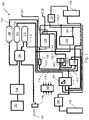
- Fig. 1 illustrates an exemplary brake system layout for an Anti-lock Braking System (ABS) 100 in accordance with an embodiment of the present invention.
- ABS Anti-lock Braking System
- ABS 100 includes a compressor 102, which functions with the help or assistance form the output power from an international combustion (IC) engine (not shown in fig. 1 ) of a vehicle or an input shaft (not shown in fig. 1 ) of compressor 102 is connected to an output crankshaft (not shown in fig. 1 ) of the IC engine.
- the compressed air from compressor 102 is thereafter sent to an air-drying and/or filtering unit 104.
- compressor 102 assists ABS 100 in creating and maintaining the pressure preferably in the range of 7.2 and 8.1 bar within the brake circuit.
- multi-circuit protection valve 106 that transmits the air to three reservoirs I, II, and III (labeled as reservoirs 108, 110 and 112) as shown in fig. 1 .
- multi-circuit protection valve 106 can be a four-circuit protection valve or quadruple-circuit protection valve.
- One of the outlets of four-circuit protection valve 106 is connected to safety valve 144 for limiting the pressure within the brake circuit within a permissible range. In case of excess pressure present within the brake circuit is released via outlet 142 as allowed or permitted by safety valve 144.
- first and second reservoirs 108, 110 are connected to a foot brake valve 124 via first and second connecting lines 114 and 116, respectively.
- first and second connecting lines 114 and 116 respectively.
- a first part 114.1 of first connecting line 114 leads to foot brake valve 124.
- each of first and second connecting lines 114 and 116 connected to foot brake valve 124 could be assigned for supplying control brake pressure the front and rear axles of the vehicle. This is derivable from Fig. 1 where one of the outlets of foot brake valve 124 leads to ABS valve 134 of the front axle where another of the outlets of foot brake valve 124 leads to ABS valve 132 of the rear axle.
- the compressed air from third reservoir 112 leads to hand brake valve 122 via lines 118, 118.1 and 122.1 and a relay valve 126 via line 122.2 according to the present embodiment.
- Relay valve 126 can be activated by control pressure received from e.g., hand brake valve 122 via e.g., a control line 122.2. It is, for instance, recognizable that hand brake valve 122 of ABS 100 is for activating the parking brake of the vehicle.
- relay valve 126 is explained in detailed in the embodiments associated with Figs. 2, 2a , 3 , 4a -4c . Further, a second part 114.2 of first connecting line 114 from reservoir 108 leads to relay valve 126, as can be taken from fig. 1 . The outlet from relay valve 126 reaches directly to a first brake actuator 136 associated with one of the wheels (not shown in Fig. 1 ) of the vehicle.
- Hand brake valve 122 furthermore is connected to a trailer control valve 130 via control line 122.3.
- ABS valve 132 is arranged before brake actuator 136.
- ABS valve 132 is similar to the construction of the conventional ABS valves and can be electronically controlled to open and/or close for varying time durations in order to arrive at an optimum condition taking the momentary braking conditions into account.
- a brake modulator 128 which receives the supply pressure from reservoir 110 via line 116 is configured to selectively transmit the supply pressure to ABS valve 132 via first supply line 128.1 and to trailer control valve 130 via second supply line 128.2.
- Trailer control valve 130 is connected to the trailer brakes (not shown in fig. 1 ) via a coupling 'CH2' (a.k.a. "trailer coupling"). From the trailer coupling, the brake pressure reaches respective trailer brake cylinders (not shown in the enclosed figures).
- ABS 100 additionally includes an electronic control unit 140 (or ECU), which can, for instance, be wirelessly connected to other components within ABS 100.
- ECU electronice control unit
- ABS 100 may have one or more pressure sensors at different connection lines such as 114, 116, 118 and their sub-divisions such as 114.1, 114.2,118.1 throughout ABS 100 to determine whether there are any disconnection or breaking down in the pressure lines or if there are any drops in the pressure in any of the lines.
- the output of the determination from the one or more pressure sensors is then transferred to ECU 140, which determines, for instance, that there is indeed a pressure drop in one of the connecting lines and may determine corrective measures to be taken (along with a warning signal to the driver of the vehicle).
- ABS system 100 Further details regarding ABS system 100 is explained in conjunction with the details that is necessary to the extent the explanation regarding relay valve 126 of the present invention.
- Fig. 2 illustrates relay valve 126 used in ABS system 100 in accordance with an embodiment of the present invention.
- Relay valve 126 for a pneumatic brake system 100.
- Relay valve 126 comprises a housing 214, a first control pressure port P42 receiving a first control brake pressure for applying e.g., a parking brake, a second control pressure port P41 receiving a second control brake pressure for applying a service brake, wherein the second control brake pressure is configured to be independently applied to that of the first control brake pressure, preferably the first control brake pressure and second control brake pressure are received from at least two independent pressurized fluid sources 110, 112 (see reservoirs 110 and 112 of Fig. 1 ).
- the parking brake may refer to the control pressure received from hand brake valve 122 (see Fig. 1 ), which is typically present within a driver's cabin.
- the service brake refers to the control pressure received from foot brake valve 124 (see Fig. 1 ).
- Relay valve 126 further comprises a pressurized fluid inlet (P1) for receiving supply pressure from at least two independent pressurized fluid sources 110, 112 and selectively take the supply pressure from only one of the at least two independent pressurized fluid sources 110, 112, a pressurized fluid outlet (P2) selectively pneumatically connected with the pressurized fluid inlet P1 when the pressure received either at first control pressure port P42 or at second control pressure port P41 when the pressure is higher than a predetermined threshold, and wherein relay valve 126 further comprises a check valve 202 coaxially positioned with respect to the pressurized fluid inlet P1 within housing 214.
- P1 pressurized fluid inlet
- P2 for receiving supply pressure from at least two independent pressurized fluid sources 110, 112 and selectively take the supply pressure from only one of the at least two independent pressurized fluid sources 110, 112, a pressurized fluid outlet (P2) selectively pneumatically connected with the pressurized fluid inlet P1 when the pressure received either at first control pressure port P42 or at second
- check valve 202 within housing 214 as shown in figs. 2 and 2a .
- check valve 202 is merely provided as an insert at pressurized fluid inlet P1.
- the simplified construction of check valve 202 and its individual features will be explained in detail in association with figures 2a , 3 , 4a to 4c of the present application.
- pressurized fluid inlet P1 is connected to a filter 206, or an air filter for removing moisture and impurities in air entering inlet P1.
- Fig. 2a illustrates an enhanced view of a portion of a relay valve shown in Fig. 2 in accordance with the same embodiment or a different advantageous embodiment of the present invention.
- check valve 202 is sung fit to an internal surface of the pressurized fluid inlet P1.
- the internal surface can be an inner generally cylindrical surface 320 as shown in Fig. 2a .
- Inner generally cylindrical surface 320 has at notches 210 and 212 so that the position of check valve 202 is snugly secured.
- check valve 202 can be inserted as a unit along inner generally cylindrical surface 320 without the difficulty of aligning a central axis of check valve 202 with central axis 322 of pressurized fluid inlet P1.
- inner generally cylindrical surface 320 aligns the position of check valve 202 automatically due to its generally cylindrical structure to be coaxial. This helps in achieving the minimum assembly line efficiency when check valve 202 must be assembled to relay valve 126.
- Fig. 2a illustrates check valve 202 as a two-piece check valve wherein first and second pieces 302, 304 of said two-piece check valve are coaxial to each other and form a preassembled unit to be inserted into the pressurized fluid inlet P1.
- first and second pieces 302, 304 are configured to be preassembled before the preassembled unit can be inserted into pressurized fluid inlet P1.
- this preassembled unit can be inserted into pressurized fluid inlet P1 without complicated procedure.
- Fig. 2a also shows that check valve 202, in particular, first piece 302 of check valve 202 includes a plurality of holes 310 for letting the pressurized air pass through it and impinge on the second piece 304.
- This feature can be clearly realized with the aid of Fig. 2a where two holes 310 are shown due to the cross-sectional view or an enhanced cross-sectional view of a section of relay valve 126 has been displayed.
- having more than one hole 310 within first piece 302 establishes better and/or more equal force transmission of pressurized air impinging on first piece 302 onto second piece 304.
- check valve 202 in association with relay valve 126 of the present invention is explained in the following sections of the detailed description.
- Figs. 3 , 4a, 4b and 4c illustrate check valve 202 and its details as used in relay valve 126 of ABS system 100 in accordance with the present invention.
- first piece 302 includes a receiving slot 308 and second piece 304 includes at least one circular extension 306, wherein first and second pieces 302, 304 are assembled such that receiving slot 308 accommodates said at least one circular extension 306 of second piece 304 to form a snap fit.
- Such an arrangement of snap fit between first and second pieces 302 and 304 is for providing a preassembled unit of check valve 202 as explained above in reference to Figs. 2 and 2a .
- second piece 304 is made of an elastomeric material which enables the user to expand and place it at a gap (not labeled in fig. 3 ) present at circular extension 306. This forms a snap fit between first and second pieces 302 and 304. It is also recognizable that second piece 304 is flexible enough to move when the pressurized air enters via hole 310 (only one hole 310 is shown in fig. 3 , but first piece 302 has plurality of holes 310).
- second piece 304 When the pressurized air via hole 310 impinges on second piece 304, it lifts second piece 304 (briefly) off surface 314 of first piece 302.
- the direction of flow of the pressurized air through hole 310 is shown with the help of arrow mark 330.
- second piece 304 includes a contact part 312 of second piece 304 touching surface 314 of first piece 302. It may be derivable that, in order to let the pressurized fluid to pass through check valve 202, contact part 312 of second piece 304 should be lifted off surface 314.
- the elastomeric material and its composition may have to be carefully chosen considering the pressure created by the pressurized fluid from port P1.
- the material of second piece 304 needs to be lifted off surface 314 as long as there is a flow of pressurized air through hole 310.
- both first piece 302 and second piece 304 of check valve 202 are made of the elastomeric material.
- the thickness of the wall of first piece 302 is larger than the thickness of second piece 304.
- the pressure applied via e.g., port or inlet P1 does not deform first piece 302 but lifts second piece 304 off surface 314 of first piece 302.
- the functionality of check valve 202 can be achieved due to the varying wall thickness of first and second pieces 302 and 304.
- plurality of holes 310 are circumferentially symmetrically distributed in second piece 304 with respect to a geometric center point 316 of second piece 304.
- the technical advantage of providing plurality of holes 310 in such a circumferentially symmetrically distributed fashion is to enable equal pressure on second piece 304, which in turn lifts second piece 304 from surface 314 of first piece 302.
- first piece 302 is made of material that is harder than the material used for second piece 304.
- the pressurized air impinging on first piece 302 (and passing through holes 310) enables lifting of second piece 304 temporarily from an external surface 314 of second piece 304 such that the pressurized air enters a relay valve chamber 204 of relay valve 126.
Landscapes
- Engineering & Computer Science (AREA)
- Transportation (AREA)
- Mechanical Engineering (AREA)
- Physics & Mathematics (AREA)
- Fluid Mechanics (AREA)
- Valves And Accessory Devices For Braking Systems (AREA)
Abstract
Description
- The present invention relates to a relay valve for a pneumatic brake system. In particular, the relay valve for the pneumatic brake system is applied in commercial vehicle brake systems.
- Conventional relay valves include a variety of methods and devices to prevent backflow of the pressurized air when said pressurized air is supplied from an independent fluid source. The importance of said methods and devices to prevent backflow of the pressurized air is found to be more important because a constant pressure magnitude needs to be maintained in a supply line connected to said relay valves.
- It is however often the case that said devices for preventing backflow of the pressurized air is either complex and are positioned at locations with a brake circuit that may increase the costs and/or time involved in assembling said devices to the existing brake circuit. One such relay valve is disclosed in
US patent publication 5624163 . - Accordingly, it is one of the objectives of the present invention that provides a device for preventing backflow of the pressurized air from an inlet of the relay valves that is not only functionally less complicated, but also easy to assemble and costs less for the manufacturing.
- In accordance with an embodiment of the present invention, a relay valve for a pneumatic brake system is disclosed. The relay valve comprises a housing, a first control pressure port receiving a first control brake pressure for applying, preferably a parking brake, a second control pressure port receiving a second control brake pressure for applying, preferably a service brake. It is noted that, for instance, a parking brake can be applied through the activation of a hand brake valve present in the driver's cabin whereas a service brake is activated via a brake pedal provided in the driver's cabin. Furthermore, in accordance with the present embodiment, the second control brake pressure is configured to be independently applied to that of the first control brake pressure, preferably the first control brake pressure and second control brake pressure are received from at least two independent pressurized fluid sources. The relay valve further comprises a pressurized fluid inlet for receiving supply pressure from at least two independent pressurized fluid sources and selectively take the supply pressure from only one of the at least two independent pressurized fluid sources, a pressurized fluid outlet selectively pneumatically connected with the pressurized fluid inlet when the pressure received either at the first control pressure port or at the second control pressure port when the pressure is higher than a predetermined threshold, and wherein the relay valve further comprises a check valve coaxially positioned with respect to the pressurized fluid inlet within the housing.
- The present invention overcomes some of the technical problems present in the prior art (such as
US 5624163 cited above in the background section) by advantageously providing the check valve within the housing of the relay valve. In particular, the check valve is merely provided as an insert at pressurized fluid inlet P1. The simplified construction of the check valve and its individual features are explained in detail in association with the accompanying figures. - The further advantageous embodiments are listed in the dependent claims.
- In accordance with an embodiment of the present invention, the check valve mentioned above is sung fit to an internal surface of the pressurized fluid inlet (of the relay valve). The use of snug fit check valve at the inlet prevents any fluid leakage between the external surface of the check valve and the internal surface of the pressurized fluid inlet. Furthermore, the provision of snug fit assembly of the check valve at the pressurized fluid inlet of the relay valve makes the check valve easy to assemble or insert into the pressurized fluid inlet.
- In accordance with any of the above-mentioned embodiments of the present invention, the check valve is a two-piece check valve wherein first and second pieces of said two-piece check valve are coaxial to each other and form a preassembled unit to be inserted into the pressurized fluid inlet. In the present embodiment, the first and second pieces (i.e., the two-piece formation of the check valve) are configured to be preassembled before the preassembled unit can be inserted into pressurized fluid inlet P1. As can be ascertained by the skilled person, this preassembled unit can be inserted into pressurized fluid inlet P1 without complicated procedure during the assembly of the relay valve.
- In accordance with another embodiment of the present invention, the check valve, in particular the first piece, includes a plurality of holes for letting the pressurized air pass through it and impinge on the second piece. For instance, having more than one hole i.e., the plurality of holes within the first piece of the check valve establishes better and/or more equal force transmission of pressurized air impinging on the first piece onto the second piece. Moreover, within the context of the present invention, the design of the second piece may enable only having the plurality of the holes (but not a singular hole) in the first piece of the check valve.
- In accordance with yet another embodiment of the present invention, the relay valve of any one of the above embodiments includes the check valve with the first piece with a receiving slot and the second piece includes at least one circular extension, wherein the first and second pieces are assembled such that the receiving slot accommodates the at least one circular extension of the second piece to form a snap fit. Such an arrangement of the snap fit between the first and second pieces is for providing a preassembled unit of the check valve.
- In accordance with any one of the above-mentioned embodiments, the plurality of holes of the check valve are circumferentially symmetrically distributed in the second piece with respect to a geometric center point of the second piece. The technical advantage of providing the plurality of holes in such a circumferentially symmetrically distributed fashion is to enable application of almost equal pressure on the second piece of the check valve, which pressure lifts the second piece from a surface of the first piece.
- In accordance with an exemplary embodiment of the present invention, the first piece and the second piece are made of elastomeric material. For instance, this would enable the skilled person to not vary the material requirements of the first and second pieces drastically, but to enable varying of the dimensional requirements of the first and second pieces of the check valve to achieve the required function of enabling a unidirectional flow.
- In accordance with another exemplary embodiment of the present invention, the first piece is made of material that is harder than the material used for the second piece. For instance, by using a harder material for the first piece, the structural rigidity of the check valve can be maintained while at the same time providing a leakproof sealing between the second piece of the check valve and an internal surface of the pressurized fluid inlet. This leakproof sealing is enabled because of the flexible or elastic behavior exhibited by the second piece being sandwiched between the first piece made of harder material and the internal surface of the pressurized fluid inlet.
- In accordance with any one of the above-mentioned embodiments, the pressurized air impinging on the first piece enables lifting of the second piece temporarily from an external surface of the second piece such that the pressurized air enters a relay valve chamber of the relay valve.
- Furthermore, a pneumatic brake system is disclosed, which is preferably an Anti-lock Braking System (ABS), comprising the relay valve of any one of the above-captioned embodiments. Still furthermore, a commercial vehicle comprising the pneumatic brake system as mentioned above is disclosed.
-
-
Fig. 1 illustrates an exemplary brake system layout for an Anti-lock Braking System (ABS) in accordance with an embodiment of the present invention; -
Fig. 2 illustrates a relay valve used in an ABS system in accordance with an embodiment of the present invention; -
Fig. 2a illustrates an enhanced view of a portion of a relay valve shown inFig. 2 in accordance with an embodiment of the present invention; and -
Figs. 3 ,4a, 4b and 4c illustrate a check valve and its details as used in a relay valve of an ABS system in accordance with an embodiment of the present invention. -
Fig. 1 illustrates an exemplary brake system layout for an Anti-lock Braking System (ABS) 100 in accordance with an embodiment of the present invention. -
ABS 100 includes acompressor 102, which functions with the help or assistance form the output power from an international combustion (IC) engine (not shown infig. 1 ) of a vehicle or an input shaft (not shown infig. 1 ) ofcompressor 102 is connected to an output crankshaft (not shown infig. 1 ) of the IC engine. The compressed air fromcompressor 102 is thereafter sent to an air-drying and/or filteringunit 104. For instance,compressor 102assists ABS 100 in creating and maintaining the pressure preferably in the range of 7.2 and 8.1 bar within the brake circuit. The filtered, dried air from the air-drying and/or filteringunit 104 reaches amulti-circuit protection valve 106 that transmits the air to three reservoirs I, II, and III (labeled asreservoirs fig. 1 . For instance,multi-circuit protection valve 106 can be a four-circuit protection valve or quadruple-circuit protection valve. One of the outlets of four-circuit protection valve 106 is connected to safety valve 144 for limiting the pressure within the brake circuit within a permissible range. In case of excess pressure present within the brake circuit is released viaoutlet 142 as allowed or permitted by safety valve 144. - Further, the air from first and
second reservoirs foot brake valve 124 via first and second connectinglines line 114 leads tofoot brake valve 124. In accordance with one exemplary implementation, each of first and second connectinglines foot brake valve 124 could be assigned for supplying control brake pressure the front and rear axles of the vehicle. This is derivable fromFig. 1 where one of the outlets offoot brake valve 124 leads toABS valve 134 of the front axle where another of the outlets offoot brake valve 124 leads toABS valve 132 of the rear axle. - The compressed air from
third reservoir 112 leads tohand brake valve 122 vialines 118, 118.1 and 122.1 and arelay valve 126 via line 122.2 according to the present embodiment.Relay valve 126 can be activated by control pressure received from e.g.,hand brake valve 122 via e.g., a control line 122.2. It is, for instance, recognizable thathand brake valve 122 ofABS 100 is for activating the parking brake of the vehicle. - It is noted that
relay valve 126 is explained in detailed in the embodiments associated withFigs. 2, 2a ,3 ,4a -4c . Further, a second part 114.2 of first connectingline 114 fromreservoir 108 leads torelay valve 126, as can be taken fromfig. 1 . The outlet fromrelay valve 126 reaches directly to afirst brake actuator 136 associated with one of the wheels (not shown inFig. 1 ) of the vehicle. -
Hand brake valve 122 furthermore is connected to atrailer control valve 130 via control line 122.3.ABS valve 132 is arranged beforebrake actuator 136.ABS valve 132 is similar to the construction of the conventional ABS valves and can be electronically controlled to open and/or close for varying time durations in order to arrive at an optimum condition taking the momentary braking conditions into account. - A
brake modulator 128 which receives the supply pressure fromreservoir 110 vialine 116 is configured to selectively transmit the supply pressure toABS valve 132 via first supply line 128.1 and totrailer control valve 130 via second supply line 128.2.Trailer control valve 130 is connected to the trailer brakes (not shown infig. 1 ) via a coupling 'CH2' (a.k.a. "trailer coupling"). From the trailer coupling, the brake pressure reaches respective trailer brake cylinders (not shown in the enclosed figures). -
ABS 100 additionally includes an electronic control unit 140 (or ECU), which can, for instance, be wirelessly connected to other components withinABS 100. What is, however, not shown inFig. 1 is that,ABS 100 may have one or more pressure sensors at different connection lines such as 114, 116, 118 and their sub-divisions such as 114.1, 114.2,118.1 throughoutABS 100 to determine whether there are any disconnection or breaking down in the pressure lines or if there are any drops in the pressure in any of the lines. The output of the determination from the one or more pressure sensors is then transferred toECU 140, which determines, for instance, that there is indeed a pressure drop in one of the connecting lines and may determine corrective measures to be taken (along with a warning signal to the driver of the vehicle). - Further details regarding
ABS system 100 is explained in conjunction with the details that is necessary to the extent the explanation regardingrelay valve 126 of the present invention. -
Fig. 2 illustratesrelay valve 126 used inABS system 100 in accordance with an embodiment of the present invention. -
Relay valve 126 for apneumatic brake system 100.Relay valve 126 comprises ahousing 214, a first control pressure port P42 receiving a first control brake pressure for applying e.g., a parking brake, a second control pressure port P41 receiving a second control brake pressure for applying a service brake, wherein the second control brake pressure is configured to be independently applied to that of the first control brake pressure, preferably the first control brake pressure and second control brake pressure are received from at least two independent pressurizedfluid sources 110, 112 (seereservoirs Fig. 1 ). In the present embodiment, the parking brake may refer to the control pressure received from hand brake valve 122 (seeFig. 1 ), which is typically present within a driver's cabin. In the same embodiment, the service brake refers to the control pressure received from foot brake valve 124 (seeFig. 1 ). -
Relay valve 126, according to the present embodiment, further comprises a pressurized fluid inlet (P1) for receiving supply pressure from at least two independent pressurizedfluid sources fluid sources relay valve 126 further comprises acheck valve 202 coaxially positioned with respect to the pressurized fluid inlet P1 withinhousing 214. - In general, it is known in the prior art such as
US5624163A , which is also cited in the background section above, to provide the check valves "outside" the housing of the conventional relay valves due the constructional complexity involved in incorporating such a check valve within the housing of the conventional relay valve. Furthermore, the design of the relay valves and their corresponding check valves should be adjusted so that the individual components do not become over-expensive and at the same time provide easy assembly procedure. In convention check valves, the structure may include e.g., a spring and a ball or spool to open and close the valve for allowing unidirectional flow. - The present invention overcomes the above said technical problems by advantageously providing
check valve 202 withinhousing 214 as shown infigs. 2 and 2a . In particular,check valve 202 is merely provided as an insert at pressurized fluid inlet P1. The simplified construction ofcheck valve 202 and its individual features will be explained in detail in association withfigures 2a ,3 ,4a to 4c of the present application. - In accordance with an embodiment, as shown in
Fig. 2 , pressurized fluid inlet P1 is connected to afilter 206, or an air filter for removing moisture and impurities in air entering inlet P1. -
Fig. 2a illustrates an enhanced view of a portion of a relay valve shown inFig. 2 in accordance with the same embodiment or a different advantageous embodiment of the present invention. In this advantageous embodiment, as also shown inFig. 2a check valve 202 is sung fit to an internal surface of the pressurized fluid inlet P1. For instance, the internal surface can be an inner generallycylindrical surface 320 as shown inFig. 2a . Inner generallycylindrical surface 320 has atnotches check valve 202 is snugly secured. - The presence of
notches 210und 212 is particularly advantageous because in a typical assembly line ofmanufacturing relay valve 126,check valve 202 can be inserted as a unit along inner generallycylindrical surface 320 without the difficulty of aligning a central axis ofcheck valve 202 withcentral axis 322 of pressurized fluid inlet P1. In other words, inner generallycylindrical surface 320 aligns the position ofcheck valve 202 automatically due to its generally cylindrical structure to be coaxial. This helps in achieving the minimum assembly line efficiency whencheck valve 202 must be assembled to relayvalve 126. - Furthermore,
Fig. 2a illustratescheck valve 202 as a two-piece check valve wherein first andsecond pieces second pieces - In continuation of the present embodiment,
Fig. 2a also shows thatcheck valve 202, in particular,first piece 302 ofcheck valve 202 includes a plurality ofholes 310 for letting the pressurized air pass through it and impinge on thesecond piece 304. This feature can be clearly realized with the aid ofFig. 2a where twoholes 310 are shown due to the cross-sectional view or an enhanced cross-sectional view of a section ofrelay valve 126 has been displayed. Naturally, having more than onehole 310 withinfirst piece 302 establishes better and/or more equal force transmission of pressurized air impinging onfirst piece 302 ontosecond piece 304. - Further details of
check valve 202 in association withrelay valve 126 of the present invention are explained in the following sections of the detailed description. -
Figs. 3 ,4a, 4b and 4c illustratecheck valve 202 and its details as used inrelay valve 126 ofABS system 100 in accordance with the present invention. - As can be seen in
Fig. 3 ,first piece 302 includes a receivingslot 308 andsecond piece 304 includes at least onecircular extension 306, wherein first andsecond pieces slot 308 accommodates said at least onecircular extension 306 ofsecond piece 304 to form a snap fit. Such an arrangement of snap fit between first andsecond pieces check valve 202 as explained above in reference toFigs. 2 and 2a . - Working mode of
check valve 202 is briefly explained herewith. As can be seen infig. 3 ,check valve 202 and its first andsecond pieces second piece 304 is made of an elastomeric material which enables the user to expand and place it at a gap (not labeled infig. 3 ) present atcircular extension 306. This forms a snap fit between first andsecond pieces second piece 304 is flexible enough to move when the pressurized air enters via hole 310 (only onehole 310 is shown infig. 3 , butfirst piece 302 has plurality of holes 310). When the pressurized air viahole 310 impinges onsecond piece 304, it lifts second piece 304 (briefly) offsurface 314 offirst piece 302. The direction of flow of the pressurized air throughhole 310 is shown with the help ofarrow mark 330. For instance, inFig. 3 ,second piece 304 includes acontact part 312 ofsecond piece 304touching surface 314 offirst piece 302. It may be derivable that, in order to let the pressurized fluid to pass throughcheck valve 202,contact part 312 ofsecond piece 304 should be lifted offsurface 314. - It is briefly noted that the elastomeric material and its composition may have to be carefully chosen considering the pressure created by the pressurized fluid from port P1. In particular, the material of
second piece 304 needs to be lifted offsurface 314 as long as there is a flow of pressurized air throughhole 310. - In accordance with an embodiment, both
first piece 302 andsecond piece 304 ofcheck valve 202 are made of the elastomeric material. In the present embodiment, as can also be taken fromfig. 3 , the thickness of the wall offirst piece 302 is larger than the thickness ofsecond piece 304. Thus, the pressure applied via e.g., port or inlet P1 (seefig. 2 ) does not deformfirst piece 302 but liftssecond piece 304 offsurface 314 offirst piece 302. As a result, despite havingfirst piece 302 andsecond piece 304 made of the same material, the functionality ofcheck valve 202 can be achieved due to the varying wall thickness of first andsecond pieces - Furthermore, as can be realized from
Fig. 4b , it is preferred that plurality ofholes 310 are circumferentially symmetrically distributed insecond piece 304 with respect to ageometric center point 316 ofsecond piece 304. The technical advantage of providing plurality ofholes 310 in such a circumferentially symmetrically distributed fashion is to enable equal pressure onsecond piece 304, which in turn liftssecond piece 304 fromsurface 314 offirst piece 302. - It is also preferred, that
first piece 302 is made of material that is harder than the material used forsecond piece 304. - As also explained above, the pressurized air impinging on first piece 302 (and passing through holes 310) enables lifting of
second piece 304 temporarily from anexternal surface 314 ofsecond piece 304 such that the pressurized air enters arelay valve chamber 204 ofrelay valve 126. -
- 100 - ABS or an exemplary pneumatic brake system
- 102 - compressor
- 104 - air-drying and/or filtering unit
- 106 - multi-circuit protection valve
- 108 - first reservoir
- 110 - second reservoir
- 112 - third reservoir
- 114 - first connecting line starting from
reservoir 108 - 116 - second connecting line starting from
reservoir 110 - 118 - third connecting line starting from
reservoir 112 - 120 - a check valve for third connecting
line 118 - 122 - hand brake valve or parking brake valve
- 124 - foot brake valve
- 126 - relay valve
- 128 - brake modulator
- 130 - trailer control valve
- 132 - first ABS valve
- 134 - second ABS valve
- 136 - first brake actuator
- 138 - second brake actuator
- 140 - Electron Control Unit (ECU)
- 142 - outlet
- 144 - safety valve for limiting the pressure within the brake circuit within a permissible range
- 114.1 - first part of first connecting
line 114 - 114.2 - second part of first connecting
line 114 - 118.1 - first part of third connecting
line 118 - 118.2 - second part of third connecting
line 118 - 122.1 - inlet part of
hand brake valve 122 - 122.2 - first outlet part of
hand brake valve 122 - 122.3 - second outlet part of
hand brake valve 122 - 128.1 - first supply line of
brake modulator 128 - 128.2 - second supply line of
brake modulator 128 - P1 - pressurized fluid inlet of
relay valve 126 - P2 - pressurized fluid outlet of
relay valve 126 - P41 - second control pressure port of
relay valve 126 - P42 - first control pressure port of
relay valve 126 - 202 - check valve
- 204 - relay valve chamber
- 206 - filter
- 208 - internal surface of pressurized fluid outlet of
relay valve 126 - 210, 212 - notches at pressurized fluid inlet P1 receiving
check valve 202 - 214 - housing
- 302, 304 - first and second pieces of
check valve 202 - 306 - circular extension
- 308 - receiving slot
- 310 - plurality of holes present at
first piece 302 - 312 - contact part of
second piece 304touching surface 314 offirst piece 302 - 314 - external surface of
first piece 302 - 316 - a geometric center point
- 320 - inner generally cylindrical surface of pressurized fluid inlet P1
- 322 - central axis of pressurized fluid inlet P1
Claims (11)
- A relay valve (126) for a pneumatic brake system (100), comprisinga housing (214);a first control pressure port (P42) receiving a first control brake pressure for applying, preferably a parking brake;a second control pressure port (P41) receiving a second control brake pressure for applying, preferably a service brake,wherein the second control brake pressure is configured to be independently applied to that of the first control brake pressure, preferably the first control brake pressure and second control brake pressure are received from at least two independent pressurized fluid sources (110, 112);a pressurized fluid inlet (P1) for receiving supply pressure from at least two independent pressurized fluid sources (110, 112) and selectively take the supply pressure from only one of the at least two independent pressurized fluid sources (110, 112);a pressurized fluid outlet (P2) selectively pneumatically connected with the pressurized fluid inlet (P1) when the pressure received either at the first control pressure port (P42) or at the second control pressure port (P41) when the pressure is higher than a predetermined threshold; andwherein the relay valve (126) further comprises a check valve (202) coaxially positioned with respect to the pressurized fluid inlet (P1) within the housing (214).
- The relay valve (126) of claim 1, wherein the check valve (202) is sung fit to an internal surface of the pressurized fluid inlet (P1).
- The relay valve (126) of any one of the above claims, wherein the check valve (202) is a two-piece check valve wherein first and second pieces (302, 304) of said two-piece check valve are coaxial to each other and form a preassembled unit to be inserted into the pressurized fluid inlet (P1).
- The relay valve (126) of claim 3, wherein the check valve (202), in particular the first piece (302) includes a plurality of holes (310) for letting the pressurized air pass through it and impinge on the second piece (304).
- The relay valve (126) of any one of claims 3 and 4, wherein the first piece (302) includes a receiving slot (308) and the second piece (304) includes at least one circular extension (306), wherein the first and second pieces (302, 304) are assembled such that the receiving slot (308) accommodates said at least one circular extension (306) of the second piece (304) to form a snap fit.
- The relay valve of any one of the claims 4 and 5, wherein the plurality of holes (310) are circumferentially symmetrically distributed in the second piece (304) with respect to a geometric center point (316) of the second piece (304).
- The relay valve of any one of the claims 3 to 6, wherein the first piece (302) and the second piece (304) are made of elastomeric material.
- The relay valve (126) of any one of claims 3 to 6, wherein the first piece (302) is made of material that is harder than the material used for the second piece (304).
- The relay valve (126) of any one of claims 3 to 8, wherein the pressurized air impinging on the first piece (302) enables lifting of the second piece (304) temporarily from an external surface (314) of the second piece (304) such that the pressurized air enters a relay valve chamber (204) of the relay valve (126).
- A pneumatic brake system (100), preferably an Anti-lock Braking System (ABS) (100), comprising the relay valve (126) of any one of the above-captioned claims.
- A commercial vehicle comprising the pneumatic brake system (100) of claim 10.
Priority Applications (1)
| Application Number | Priority Date | Filing Date | Title |
|---|---|---|---|
| EP21170108.1A EP4079588B1 (en) | 2021-04-23 | 2021-04-23 | A relay valve for a pneumatic brake system |
Applications Claiming Priority (1)
| Application Number | Priority Date | Filing Date | Title |
|---|---|---|---|
| EP21170108.1A EP4079588B1 (en) | 2021-04-23 | 2021-04-23 | A relay valve for a pneumatic brake system |
Publications (2)
| Publication Number | Publication Date |
|---|---|
| EP4079588A1 true EP4079588A1 (en) | 2022-10-26 |
| EP4079588B1 EP4079588B1 (en) | 2024-06-05 |
Family
ID=75659886
Family Applications (1)
| Application Number | Title | Priority Date | Filing Date |
|---|---|---|---|
| EP21170108.1A Active EP4079588B1 (en) | 2021-04-23 | 2021-04-23 | A relay valve for a pneumatic brake system |
Country Status (1)
| Country | Link |
|---|---|
| EP (1) | EP4079588B1 (en) |
Citations (4)
| Publication number | Priority date | Publication date | Assignee | Title |
|---|---|---|---|---|
| US5624163A (en) | 1995-02-10 | 1997-04-29 | Wabco Gmbh | Pressure medium actuated vehicle braking system |
| DE19510492C2 (en) * | 1995-03-23 | 2003-12-11 | Wabco Gmbh & Co Ohg | Relay valve arrangement |
| CN204296700U (en) * | 2014-12-16 | 2015-04-29 | 齐齐哈尔轨道交通装备有限责任公司 | Relay valve |
| CN206691102U (en) * | 2017-01-17 | 2017-12-01 | 瑞立集团瑞安汽车零部件有限公司 | A kind of servo combination valve |
-
2021
- 2021-04-23 EP EP21170108.1A patent/EP4079588B1/en active Active
Patent Citations (5)
| Publication number | Priority date | Publication date | Assignee | Title |
|---|---|---|---|---|
| US5624163A (en) | 1995-02-10 | 1997-04-29 | Wabco Gmbh | Pressure medium actuated vehicle braking system |
| EP0726189B1 (en) * | 1995-02-10 | 1998-07-22 | WABCO GmbH | Pressure operated vehicle brake installation |
| DE19510492C2 (en) * | 1995-03-23 | 2003-12-11 | Wabco Gmbh & Co Ohg | Relay valve arrangement |
| CN204296700U (en) * | 2014-12-16 | 2015-04-29 | 齐齐哈尔轨道交通装备有限责任公司 | Relay valve |
| CN206691102U (en) * | 2017-01-17 | 2017-12-01 | 瑞立集团瑞安汽车零部件有限公司 | A kind of servo combination valve |
Also Published As
| Publication number | Publication date |
|---|---|
| EP4079588B1 (en) | 2024-06-05 |
Similar Documents
| Publication | Publication Date | Title |
|---|---|---|
| EP2750945B1 (en) | Vehicle braking system | |
| EP2380792A1 (en) | Brake-by-wire system | |
| US6662824B2 (en) | Check valve slantedly biased against pressure-imposing direction | |
| CN113039102A (en) | Relay valve module for use as axle modulator and trailer control module | |
| CN101312864A (en) | Electropneumatic Brake Control | |
| CN101801745A (en) | Parking brake modulator and use of a brake modulator as a parking brake modulator | |
| US4938541A (en) | Remote power assist hydraulic antilock braking system | |
| US6116280A (en) | Spring brake valve having a balance piston with integral quick release | |
| CN101460345A (en) | Hydraulic vehicle brake system having a service brake which can be actuated by muscle force and having a device for regulating the wheel slip | |
| EP4079588B1 (en) | A relay valve for a pneumatic brake system | |
| US6179391B1 (en) | Relay valve with integral biased double check valve | |
| US5960629A (en) | Control apparatus for a brake booster | |
| EP0956227B1 (en) | Pneumatically-operated braking system for tractor-trailer combinations | |
| IT1182587B (en) | SERVOAUTOMODULATOR OF BRAKING FOR TRAILED VEHICLES EQUIPPED WITH A PNEUMATIC BRAKING SYSTEM | |
| JPH0661631U (en) | Antilock modulator | |
| JP2007511396A (en) | Valve seat for control valve in vehicle brake system | |
| US6766644B2 (en) | Master cylinder with by-pass function and proportioning valve | |
| JPH0676052B2 (en) | Trip differential pressure dash control valve using the same plunger | |
| WO2002087938A3 (en) | Electropneumatic control valve with a seal arrangement | |
| EP1747133B1 (en) | Improvements in air dryers | |
| CN223384444U (en) | Valve device for vehicle electronic brake system and vehicle electronic brake system | |
| JPH09511717A (en) | Switching valve for multi-circuit braking systems of motor vehicles | |
| CN103978967B (en) | Mechanical hydraulic brake booster with extension for autonomous braking | |
| JPS5928933Y2 (en) | Valve for automobile fluid pressure brake system | |
| JPS6215388B2 (en) |
Legal Events
| Date | Code | Title | Description |
|---|---|---|---|
| PUAI | Public reference made under article 153(3) epc to a published international application that has entered the european phase |
Free format text: ORIGINAL CODE: 0009012 |
|
| STAA | Information on the status of an ep patent application or granted ep patent |
Free format text: STATUS: THE APPLICATION HAS BEEN PUBLISHED |
|
| AK | Designated contracting states |
Kind code of ref document: A1 Designated state(s): AL AT BE BG CH CY CZ DE DK EE ES FI FR GB GR HR HU IE IS IT LI LT LU LV MC MK MT NL NO PL PT RO RS SE SI SK SM TR |
|
| STAA | Information on the status of an ep patent application or granted ep patent |
Free format text: STATUS: REQUEST FOR EXAMINATION WAS MADE |
|
| 17P | Request for examination filed |
Effective date: 20230426 |
|
| RBV | Designated contracting states (corrected) |
Designated state(s): AL AT BE BG CH CY CZ DE DK EE ES FI FR GB GR HR HU IE IS IT LI LT LU LV MC MK MT NL NO PL PT RO RS SE SI SK SM TR |
|
| GRAP | Despatch of communication of intention to grant a patent |
Free format text: ORIGINAL CODE: EPIDOSNIGR1 |
|
| STAA | Information on the status of an ep patent application or granted ep patent |
Free format text: STATUS: GRANT OF PATENT IS INTENDED |
|
| INTG | Intention to grant announced |
Effective date: 20240327 |
|
| RIC1 | Information provided on ipc code assigned before grant |
Ipc: B60T 15/20 20060101ALI20240315BHEP Ipc: B60T 8/38 20060101ALI20240315BHEP Ipc: B60T 8/32 20060101ALI20240315BHEP Ipc: B60T 13/68 20060101AFI20240315BHEP |
|
| GRAS | Grant fee paid |
Free format text: ORIGINAL CODE: EPIDOSNIGR3 |
|
| GRAA | (expected) grant |
Free format text: ORIGINAL CODE: 0009210 |
|
| STAA | Information on the status of an ep patent application or granted ep patent |
Free format text: STATUS: THE PATENT HAS BEEN GRANTED |
|
| AK | Designated contracting states |
Kind code of ref document: B1 Designated state(s): AL AT BE BG CH CY CZ DE DK EE ES FI FR GB GR HR HU IE IS IT LI LT LU LV MC MK MT NL NO PL PT RO RS SE SI SK SM TR |
|
| REG | Reference to a national code |
Ref country code: CH Ref legal event code: EP |
|
| REG | Reference to a national code |
Ref country code: DE Ref legal event code: R096 Ref document number: 602021013984 Country of ref document: DE |
|
| REG | Reference to a national code |
Ref country code: IE Ref legal event code: FG4D |
|
| REG | Reference to a national code |
Ref country code: LT Ref legal event code: MG9D |
|
| PG25 | Lapsed in a contracting state [announced via postgrant information from national office to epo] |
Ref country code: BG Free format text: LAPSE BECAUSE OF FAILURE TO SUBMIT A TRANSLATION OF THE DESCRIPTION OR TO PAY THE FEE WITHIN THE PRESCRIBED TIME-LIMIT Effective date: 20240605 |
|
| REG | Reference to a national code |
Ref country code: NL Ref legal event code: MP Effective date: 20240605 |
|
| PG25 | Lapsed in a contracting state [announced via postgrant information from national office to epo] |
Ref country code: FI Free format text: LAPSE BECAUSE OF FAILURE TO SUBMIT A TRANSLATION OF THE DESCRIPTION OR TO PAY THE FEE WITHIN THE PRESCRIBED TIME-LIMIT Effective date: 20240605 Ref country code: HR Free format text: LAPSE BECAUSE OF FAILURE TO SUBMIT A TRANSLATION OF THE DESCRIPTION OR TO PAY THE FEE WITHIN THE PRESCRIBED TIME-LIMIT Effective date: 20240605 |
|
| PG25 | Lapsed in a contracting state [announced via postgrant information from national office to epo] |
Ref country code: GR Free format text: LAPSE BECAUSE OF FAILURE TO SUBMIT A TRANSLATION OF THE DESCRIPTION OR TO PAY THE FEE WITHIN THE PRESCRIBED TIME-LIMIT Effective date: 20240906 |
|
| PG25 | Lapsed in a contracting state [announced via postgrant information from national office to epo] |
Ref country code: ES Free format text: LAPSE BECAUSE OF FAILURE TO SUBMIT A TRANSLATION OF THE DESCRIPTION OR TO PAY THE FEE WITHIN THE PRESCRIBED TIME-LIMIT Effective date: 20240605 |
|
| PG25 | Lapsed in a contracting state [announced via postgrant information from national office to epo] |
Ref country code: LV Free format text: LAPSE BECAUSE OF FAILURE TO SUBMIT A TRANSLATION OF THE DESCRIPTION OR TO PAY THE FEE WITHIN THE PRESCRIBED TIME-LIMIT Effective date: 20240605 |
|
| PG25 | Lapsed in a contracting state [announced via postgrant information from national office to epo] |
Ref country code: NO Free format text: LAPSE BECAUSE OF FAILURE TO SUBMIT A TRANSLATION OF THE DESCRIPTION OR TO PAY THE FEE WITHIN THE PRESCRIBED TIME-LIMIT Effective date: 20240905 Ref country code: LV Free format text: LAPSE BECAUSE OF FAILURE TO SUBMIT A TRANSLATION OF THE DESCRIPTION OR TO PAY THE FEE WITHIN THE PRESCRIBED TIME-LIMIT Effective date: 20240605 Ref country code: HR Free format text: LAPSE BECAUSE OF FAILURE TO SUBMIT A TRANSLATION OF THE DESCRIPTION OR TO PAY THE FEE WITHIN THE PRESCRIBED TIME-LIMIT Effective date: 20240605 Ref country code: GR Free format text: LAPSE BECAUSE OF FAILURE TO SUBMIT A TRANSLATION OF THE DESCRIPTION OR TO PAY THE FEE WITHIN THE PRESCRIBED TIME-LIMIT Effective date: 20240906 Ref country code: FI Free format text: LAPSE BECAUSE OF FAILURE TO SUBMIT A TRANSLATION OF THE DESCRIPTION OR TO PAY THE FEE WITHIN THE PRESCRIBED TIME-LIMIT Effective date: 20240605 Ref country code: ES Free format text: LAPSE BECAUSE OF FAILURE TO SUBMIT A TRANSLATION OF THE DESCRIPTION OR TO PAY THE FEE WITHIN THE PRESCRIBED TIME-LIMIT Effective date: 20240605 Ref country code: BG Free format text: LAPSE BECAUSE OF FAILURE TO SUBMIT A TRANSLATION OF THE DESCRIPTION OR TO PAY THE FEE WITHIN THE PRESCRIBED TIME-LIMIT Effective date: 20240605 Ref country code: RS Free format text: LAPSE BECAUSE OF FAILURE TO SUBMIT A TRANSLATION OF THE DESCRIPTION OR TO PAY THE FEE WITHIN THE PRESCRIBED TIME-LIMIT Effective date: 20240905 |
|
| PG25 | Lapsed in a contracting state [announced via postgrant information from national office to epo] |
Ref country code: NL Free format text: LAPSE BECAUSE OF FAILURE TO SUBMIT A TRANSLATION OF THE DESCRIPTION OR TO PAY THE FEE WITHIN THE PRESCRIBED TIME-LIMIT Effective date: 20240605 |
|
| REG | Reference to a national code |
Ref country code: AT Ref legal event code: MK05 Ref document number: 1692250 Country of ref document: AT Kind code of ref document: T Effective date: 20240605 |
|
| PG25 | Lapsed in a contracting state [announced via postgrant information from national office to epo] |
Ref country code: NL Free format text: LAPSE BECAUSE OF FAILURE TO SUBMIT A TRANSLATION OF THE DESCRIPTION OR TO PAY THE FEE WITHIN THE PRESCRIBED TIME-LIMIT Effective date: 20240605 |
|
| PG25 | Lapsed in a contracting state [announced via postgrant information from national office to epo] |
Ref country code: PT Free format text: LAPSE BECAUSE OF FAILURE TO SUBMIT A TRANSLATION OF THE DESCRIPTION OR TO PAY THE FEE WITHIN THE PRESCRIBED TIME-LIMIT Effective date: 20241007 |
|
| PG25 | Lapsed in a contracting state [announced via postgrant information from national office to epo] |
Ref country code: PT Free format text: LAPSE BECAUSE OF FAILURE TO SUBMIT A TRANSLATION OF THE DESCRIPTION OR TO PAY THE FEE WITHIN THE PRESCRIBED TIME-LIMIT Effective date: 20241007 |
|
| PG25 | Lapsed in a contracting state [announced via postgrant information from national office to epo] |
Ref country code: PL Free format text: LAPSE BECAUSE OF FAILURE TO SUBMIT A TRANSLATION OF THE DESCRIPTION OR TO PAY THE FEE WITHIN THE PRESCRIBED TIME-LIMIT Effective date: 20240605 |
|
| PG25 | Lapsed in a contracting state [announced via postgrant information from national office to epo] |
Ref country code: EE Free format text: LAPSE BECAUSE OF FAILURE TO SUBMIT A TRANSLATION OF THE DESCRIPTION OR TO PAY THE FEE WITHIN THE PRESCRIBED TIME-LIMIT Effective date: 20240605 |
|
| PG25 | Lapsed in a contracting state [announced via postgrant information from national office to epo] |
Ref country code: IS Free format text: LAPSE BECAUSE OF FAILURE TO SUBMIT A TRANSLATION OF THE DESCRIPTION OR TO PAY THE FEE WITHIN THE PRESCRIBED TIME-LIMIT Effective date: 20241005 Ref country code: AT Free format text: LAPSE BECAUSE OF FAILURE TO SUBMIT A TRANSLATION OF THE DESCRIPTION OR TO PAY THE FEE WITHIN THE PRESCRIBED TIME-LIMIT Effective date: 20240605 |
|
| PG25 | Lapsed in a contracting state [announced via postgrant information from national office to epo] |
Ref country code: CZ Free format text: LAPSE BECAUSE OF FAILURE TO SUBMIT A TRANSLATION OF THE DESCRIPTION OR TO PAY THE FEE WITHIN THE PRESCRIBED TIME-LIMIT Effective date: 20240605 |
|
| PG25 | Lapsed in a contracting state [announced via postgrant information from national office to epo] |
Ref country code: RO Free format text: LAPSE BECAUSE OF FAILURE TO SUBMIT A TRANSLATION OF THE DESCRIPTION OR TO PAY THE FEE WITHIN THE PRESCRIBED TIME-LIMIT Effective date: 20240605 Ref country code: SK Free format text: LAPSE BECAUSE OF FAILURE TO SUBMIT A TRANSLATION OF THE DESCRIPTION OR TO PAY THE FEE WITHIN THE PRESCRIBED TIME-LIMIT Effective date: 20240605 |
|
| PG25 | Lapsed in a contracting state [announced via postgrant information from national office to epo] |
Ref country code: SM Free format text: LAPSE BECAUSE OF FAILURE TO SUBMIT A TRANSLATION OF THE DESCRIPTION OR TO PAY THE FEE WITHIN THE PRESCRIBED TIME-LIMIT Effective date: 20240605 |
|
| PG25 | Lapsed in a contracting state [announced via postgrant information from national office to epo] |
Ref country code: SM Free format text: LAPSE BECAUSE OF FAILURE TO SUBMIT A TRANSLATION OF THE DESCRIPTION OR TO PAY THE FEE WITHIN THE PRESCRIBED TIME-LIMIT Effective date: 20240605 Ref country code: SK Free format text: LAPSE BECAUSE OF FAILURE TO SUBMIT A TRANSLATION OF THE DESCRIPTION OR TO PAY THE FEE WITHIN THE PRESCRIBED TIME-LIMIT Effective date: 20240605 Ref country code: RO Free format text: LAPSE BECAUSE OF FAILURE TO SUBMIT A TRANSLATION OF THE DESCRIPTION OR TO PAY THE FEE WITHIN THE PRESCRIBED TIME-LIMIT Effective date: 20240605 Ref country code: PL Free format text: LAPSE BECAUSE OF FAILURE TO SUBMIT A TRANSLATION OF THE DESCRIPTION OR TO PAY THE FEE WITHIN THE PRESCRIBED TIME-LIMIT Effective date: 20240605 Ref country code: IS Free format text: LAPSE BECAUSE OF FAILURE TO SUBMIT A TRANSLATION OF THE DESCRIPTION OR TO PAY THE FEE WITHIN THE PRESCRIBED TIME-LIMIT Effective date: 20241005 Ref country code: EE Free format text: LAPSE BECAUSE OF FAILURE TO SUBMIT A TRANSLATION OF THE DESCRIPTION OR TO PAY THE FEE WITHIN THE PRESCRIBED TIME-LIMIT Effective date: 20240605 Ref country code: CZ Free format text: LAPSE BECAUSE OF FAILURE TO SUBMIT A TRANSLATION OF THE DESCRIPTION OR TO PAY THE FEE WITHIN THE PRESCRIBED TIME-LIMIT Effective date: 20240605 Ref country code: AT Free format text: LAPSE BECAUSE OF FAILURE TO SUBMIT A TRANSLATION OF THE DESCRIPTION OR TO PAY THE FEE WITHIN THE PRESCRIBED TIME-LIMIT Effective date: 20240605 |
|
| PG25 | Lapsed in a contracting state [announced via postgrant information from national office to epo] |
Ref country code: IT Free format text: LAPSE BECAUSE OF FAILURE TO SUBMIT A TRANSLATION OF THE DESCRIPTION OR TO PAY THE FEE WITHIN THE PRESCRIBED TIME-LIMIT Effective date: 20240605 |
|
| REG | Reference to a national code |
Ref country code: DE Ref legal event code: R097 Ref document number: 602021013984 Country of ref document: DE |
|
| PLBE | No opposition filed within time limit |
Free format text: ORIGINAL CODE: 0009261 |
|
| STAA | Information on the status of an ep patent application or granted ep patent |
Free format text: STATUS: NO OPPOSITION FILED WITHIN TIME LIMIT |
|
| PG25 | Lapsed in a contracting state [announced via postgrant information from national office to epo] |
Ref country code: DK Free format text: LAPSE BECAUSE OF FAILURE TO SUBMIT A TRANSLATION OF THE DESCRIPTION OR TO PAY THE FEE WITHIN THE PRESCRIBED TIME-LIMIT Effective date: 20240605 |
|
| 26N | No opposition filed |
Effective date: 20250306 |
|
| PGFP | Annual fee paid to national office [announced via postgrant information from national office to epo] |
Ref country code: DE Payment date: 20250305 Year of fee payment: 5 |
|
| PG25 | Lapsed in a contracting state [announced via postgrant information from national office to epo] |
Ref country code: SE Free format text: LAPSE BECAUSE OF FAILURE TO SUBMIT A TRANSLATION OF THE DESCRIPTION OR TO PAY THE FEE WITHIN THE PRESCRIBED TIME-LIMIT Effective date: 20240605 |
|
| REG | Reference to a national code |
Ref country code: CH Ref legal event code: H13 Free format text: ST27 STATUS EVENT CODE: U-0-0-H10-H13 (AS PROVIDED BY THE NATIONAL OFFICE) Effective date: 20251125 |
|
| PG25 | Lapsed in a contracting state [announced via postgrant information from national office to epo] |
Ref country code: LU Free format text: LAPSE BECAUSE OF NON-PAYMENT OF DUE FEES Effective date: 20250423 |
|
| PG25 | Lapsed in a contracting state [announced via postgrant information from national office to epo] |
Ref country code: MC Free format text: LAPSE BECAUSE OF FAILURE TO SUBMIT A TRANSLATION OF THE DESCRIPTION OR TO PAY THE FEE WITHIN THE PRESCRIBED TIME-LIMIT Effective date: 20240605 |
|
| REG | Reference to a national code |
Ref country code: BE Ref legal event code: MM Effective date: 20250430 |
|
| PG25 | Lapsed in a contracting state [announced via postgrant information from national office to epo] |
Ref country code: BE Free format text: LAPSE BECAUSE OF NON-PAYMENT OF DUE FEES Effective date: 20250430 |
|
| PG25 | Lapsed in a contracting state [announced via postgrant information from national office to epo] |
Ref country code: CH Free format text: LAPSE BECAUSE OF NON-PAYMENT OF DUE FEES Effective date: 20250430 |
|
| PGFP | Annual fee paid to national office [announced via postgrant information from national office to epo] |
Ref country code: GB Payment date: 20260313 Year of fee payment: 6 |
|
| PG25 | Lapsed in a contracting state [announced via postgrant information from national office to epo] |
Ref country code: IE Free format text: LAPSE BECAUSE OF NON-PAYMENT OF DUE FEES Effective date: 20250423 |
|
| PGFP | Annual fee paid to national office [announced via postgrant information from national office to epo] |
Ref country code: FR Payment date: 20260309 Year of fee payment: 6 |