EP4079265B1 - Schulterstütze - Google Patents
Schulterstütze Download PDFInfo
- Publication number
- EP4079265B1 EP4079265B1 EP21169085.4A EP21169085A EP4079265B1 EP 4079265 B1 EP4079265 B1 EP 4079265B1 EP 21169085 A EP21169085 A EP 21169085A EP 4079265 B1 EP4079265 B1 EP 4079265B1
- Authority
- EP
- European Patent Office
- Prior art keywords
- shoulder
- upper arm
- arm sleeve
- brace
- shoulder pad
- Prior art date
- Legal status (The legal status is an assumption and is not a legal conclusion. Google has not performed a legal analysis and makes no representation as to the accuracy of the status listed.)
- Active
Links
Images
Classifications
-
- A—HUMAN NECESSITIES
- A61—MEDICAL OR VETERINARY SCIENCE; HYGIENE
- A61F—FILTERS IMPLANTABLE INTO BLOOD VESSELS; PROSTHESES; DEVICES PROVIDING PATENCY TO, OR PREVENTING COLLAPSING OF, TUBULAR STRUCTURES OF THE BODY, e.g. STENTS; ORTHOPAEDIC, NURSING OR CONTRACEPTIVE DEVICES; FOMENTATION; TREATMENT OR PROTECTION OF EYES OR EARS; BANDAGES, DRESSINGS OR ABSORBENT PADS; FIRST-AID KITS
- A61F5/00—Orthopaedic methods or devices for non-surgical treatment of bones or joints; Nursing devices ; Anti-rape devices
- A61F5/37—Restraining devices for the body or for body parts; Restraining shirts
- A61F5/3715—Restraining devices for the body or for body parts; Restraining shirts for attaching the limbs to other parts of the body
- A61F5/3723—Restraining devices for the body or for body parts; Restraining shirts for attaching the limbs to other parts of the body for the arms
Definitions
- a commonly known manner of relieving the shoulder is by use of a sling.
- the sling is wrapped around the forearm and around the neck of the person.
- the weight of the arm is borne by the neck and the arm is immobilized against the body.
- the neck is however not suited for carrying such a weight and after a day wearing a sling, the muscles in the neck will start to ache.
- the fact that one of the arms cannot be properly used, as it is immobilized will result in overloading other parts of the body, such as the other arm and the back.
- Such a shoulder brace has a shoulder pad held in position by an adjustable arm pit belt.
- An upper arm sleeve is furthermore provided and mounted by one or more straps to the shoulder pad.
- Such a shoulder brace allows for more freedom of movement compared to for example a sling.
- the shoulder brace provides support when the upper arm is hanging downwards, but as soon as the upper arm is lifted, the distance between the mounting points on the upper arm sleeve and the shoulder pad changes, such that the support for the shoulder is changed.
- the known shoulder braces either provide insufficient support, such that the shoulder is not relieved sufficiently and might cause blood circulation problems, or the known shoulder braces provide sufficient support, while immobilizing the full arm.
- the at least one flexible tube When the shoulder brace is worn by a user, the at least one flexible tube thus extends in a plane substantially parallel to the sagittal plane.
- the at least one wire is able to slide through the at least one flexible tube. So, when the person wearing the shoulder brace moves the upper arm back and forth parallel to the sagittal plane, the increased distance between a mounting point on one side on the upper arm sleeve and the shoulder pad is compensated, as the wire can slide though the flexible tube, by the decreased distance of a mounting on the opposite side of the upper arm sleeve.
- At least one section of the at least one flexible tube is fixed to the shoulder pad and wherein both ends of the at least one flexible tube are arranged free.
- the distance between the shoulder pad and the mounting of the end of the wire will increase.
- these ends can bend towards the movement of the upper arm such that the distance between the shoulder pad and the mounting of the ends on the upper arm sleeve are maintained more or less equal.
- the free ends of the at least one flexible tube are at least 5 cm long. This allows for sufficient flexibility to allow for movement of the upper arm in the frontal plane.
- At least two flexible tubes run parallel over the shoulder pad from the dorsal end to the ventral end and wherein wires run through each of the at least two flexible tubes and wherein both ends of each wire are arranged to the upper arm sleeve on opposite sides relative to the axis of the upper arm sleeve.
- Having at least two flexible tubes with wires running there through provides a more stable support of the upper arm sleeve and thus for a more stable support of the shoulder.
- the ends of both wires on one side of the upper arm sleeve are connected to each other and guided around a guide mounted on said one side of the upper arm sleeve.
- the flexibility of the free ends of the two flexible tubes differ between the two flexible tubes. A more stiff tube will compensate less the distance change when the upper arm is moved in the frontal plane.
- At least one end of the at least one wire is linked to a lockable spool rotationally arranged on the upper arm sleeve.
- the spool allows for a quick adjustment of the length of the wires, such that the shoulder brace can be fitted on a specific person.
- the shoulder brace further comprises a tightening mechanism attached to the upper arm sleeve and coupled to the spool, the tightening mechanism having a spring for winding a first length of cable around the spool and a manual control for manually winding a second length of cable around the spool to adjust the length of the wire.
- a tightening mechanism attached to the upper arm sleeve and coupled to the spool, the tightening mechanism having a spring for winding a first length of cable around the spool and a manual control for manually winding a second length of cable around the spool to adjust the length of the wire.
- the spring allows for any play on the wire, which contributes to the wear comfort of the shoulder brace according to the invention.
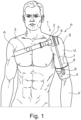
- Figure 1 shows a person P wearing a shoulder brace 1 according to the invention.
- the shoulder brace 1 has a shoulder pad 2 arranged over the shoulder S of the person P.
- an upper arm sleeve 4 is arranged around the upper arm U near the elbow where the forearm F starts.
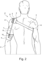
- the shoulder pad 2 is provided with two flexible tubes 5, 6 which run over the shoulder pad 2 from the dorsal end (see figure 2 ) to the ventral end (see figure 1 ).
- Two wires 7, 8 run through the flexible tubes 5, 6 respectively and are wound with one end on a spool 9 and are connected with the other ends to each other and are guided along a guide 10 (see figure 2 ).
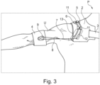
- Figure 3 shows a more detailed view of the person P of figure 1 with his upper arm U lifted up in the frontal plane.
- the flexible tubes 5, 6 are mounted to the shoulder pad 2 with mounts 11, leaving each flexible tube 5, 6 with a free end 12, 13 respectively.
- the free ends 12, 13 of the flexible tubes 5, 6 will bend when the person P lifts his upper arm U in the frontal plane and compensate for the change in distance between the spool 9 and the ends of the flexible tubes 5, 6 if they were fixed to the shoulder pad 2 and would not have been free.
Landscapes
- Health & Medical Sciences (AREA)
- Nursing (AREA)
- Orthopedic Medicine & Surgery (AREA)
- Engineering & Computer Science (AREA)
- Biomedical Technology (AREA)
- Heart & Thoracic Surgery (AREA)
- Vascular Medicine (AREA)
- Life Sciences & Earth Sciences (AREA)
- Animal Behavior & Ethology (AREA)
- General Health & Medical Sciences (AREA)
- Public Health (AREA)
- Veterinary Medicine (AREA)
- Orthopedics, Nursing, And Contraception (AREA)
Claims (8)
- Schulterstütze (1) zur Annäherung des Oberarmkopfes an das Schultergelenk einer Person (P), wobei die Schulterstütze (1) umfasst:- ein Schulterpolster (2), das dazu ausgelegt ist, über der Oberseite einer Schulter (S) einer Person (P) positioniert zu werden, wobei das Schulterpolster (2) ein dorsales Ende und ein ventrales Ende aufweist und welches Schulterpolster (2) so konfiguriert ist, dass es sich von der dorsalen Seite über die Oberseite der Schulter (S) zur ventralen Seite erstreckt;- einen verstellbaren Achselgürtel (3), wobei beide Enden des verstellbaren Achselgürtels (3) am Schulterpolster (2) angeordnet sind, wobei der verstellbare Achselgürtel (3) dazu ausgelegt ist, entlang der Achselhöhle (A) gegenüberliegend der Schulter (S) zu verlaufen, auf der das Schulterpolster (2) positioniert ist;- eine Oberarmmanschette (4), die dazu ausgelegt ist, um den Oberarm (U) einer Person (P) getragen zu werden, und so konfiguriert ist, dass sie den Oberarm (U) umschließt und sich von der ventralen Seite zur dorsalen Seite des Oberarms (U) erstreckt;- Kopplungsmittel, die mit einem Ende am Schulterpolster (2) und mit dem anderen Ende an der Oberarmmanschette (4) angeordnet sind,dadurch gekennzeichnet, dass
die Kopplungsmittel umfassen:- mindestens einen flexiblen Schlauch (5, 6), der über das Schulterpolster (2) vom dorsalen Ende zum ventralen Ende verläuft;- mindestens ein Draht (7, 8), der durch den mindestens einen flexiblen Schlauch (5, 6) verläuft, wobei beide Enden des mindestens einen Drahtes (7, 8) an der Oberarmmanschette (4) auf gegenüberliegenden Seiten relativ zur Achse der Oberarmmanschette (4) angeordnet sind. - Schulterstütze (1) nach Anspruch 1, wobei mindestens ein Abschnitt des mindestens einen flexiblen Schlauchs (5, 6) am Schulterpolster (2) befestigt ist und wobei beide Enden (12, 13) des mindestens einen flexiblen Schlauchs (5, 6) frei angeordnet sind.
- Schulterstütze (1) nach Anspruch 2, wobei die freien Enden (12, 13) des mindestens einen flexiblen Schlauchs (5, 6) mindestens 5 cm lang sind.
- Schulterstütze (1) nach einem der vorstehenden Ansprüche, wobei mindestens zwei flexible Schläuche (5, 6) parallel über das Schulterpolster (2) vom dorsalen Ende zum ventralen Ende verlaufen und wobei Drähte (7, 8) durch jeden der mindestens zwei flexiblen Schläuche (5, 6) verlaufen und wobei beide Enden jedes Drahtes (7, 8) auf gegenüberliegenden Seiten relativ zur Achse der Oberarmmanschette (4) an der Oberarmmanschette (4) angeordnet sind.
- Schulterstütze (1) nach Anspruch 4, wobei die Enden beider Drähte (7, 8) auf einer Seite der Oberarmmanschette (4) miteinander verbunden sind und um eine auf dieser einen Seite der Oberarmmanschette (4) angebrachte Führung (10) geführt sind.
- Schulterstütze (1) nach Anspruch 2 und 4 oder nach Anspruch 2 und 5, wobei die Flexibilität der freien Enden (12, 13) der beiden flexiblen Schläuche (5, 6) zwischen den beiden flexiblen Schläuchen (5, 6) unterschiedlich ist.
- Schulterstütze (1) nach einem der vorstehenden Ansprüche, wobei mindestens ein Ende des mindestens einen Drahtes (7, 8) mit einer arretierbaren Spule (9) verbunden ist, die drehbar an der Oberarmmanschette (4) angeordnet ist.
- Schulterstütze (1) nach Anspruch 7, weiter umfassend einen Spannmechanismus, der an der Oberarmmanschette (4) befestigt und mit der Spule (9) gekoppelt ist, wobei der Spannmechanismus eine Feder zum Aufwickeln einer ersten Kabellänge (7, 8) um die Spule (9) und eine manuelle Steuerung zum manuellen Aufwickeln einer zweiten Kabellänge (7, 8) um die Spule aufweist, um die Länge des Drahtes (7, 8) anzupassen.
Priority Applications (4)
| Application Number | Priority Date | Filing Date | Title |
|---|---|---|---|
| ES21169085T ES2969354T3 (es) | 2021-04-19 | 2021-04-19 | Férula de hombro |
| EP21169085.4A EP4079265B1 (de) | 2021-04-19 | 2021-04-19 | Schulterstütze |
| PL21169085.4T PL4079265T3 (pl) | 2021-04-19 | 2021-04-19 | Orteza barku |
| US17/722,868 US20220331140A1 (en) | 2021-04-19 | 2022-04-18 | Shoulder Brace |
Applications Claiming Priority (1)
| Application Number | Priority Date | Filing Date | Title |
|---|---|---|---|
| EP21169085.4A EP4079265B1 (de) | 2021-04-19 | 2021-04-19 | Schulterstütze |
Publications (3)
| Publication Number | Publication Date |
|---|---|
| EP4079265A1 EP4079265A1 (de) | 2022-10-26 |
| EP4079265C0 EP4079265C0 (de) | 2023-10-18 |
| EP4079265B1 true EP4079265B1 (de) | 2023-10-18 |
Family
ID=75581435
Family Applications (1)
| Application Number | Title | Priority Date | Filing Date |
|---|---|---|---|
| EP21169085.4A Active EP4079265B1 (de) | 2021-04-19 | 2021-04-19 | Schulterstütze |
Country Status (4)
| Country | Link |
|---|---|
| US (1) | US20220331140A1 (de) |
| EP (1) | EP4079265B1 (de) |
| ES (1) | ES2969354T3 (de) |
| PL (1) | PL4079265T3 (de) |
Families Citing this family (1)
| Publication number | Priority date | Publication date | Assignee | Title |
|---|---|---|---|---|
| DE102021129271A1 (de) * | 2021-11-10 | 2023-05-11 | Ottobock Se & Co. Kgaa | Verfahren zum Befestigen einer Orthese und Orthese |
Family Cites Families (10)
| Publication number | Priority date | Publication date | Assignee | Title |
|---|---|---|---|---|
| US3235474A (en) | 1961-10-02 | 1966-02-15 | Air Prod & Chem | Electrolytic method of producing nitrogen trifluoride |
| US5203763A (en) * | 1992-02-04 | 1993-04-20 | Lajiness O Neill Renee | Dynamic sling |
| US5403268A (en) | 1993-10-25 | 1995-04-04 | Med-Techna, Inc. | Arm support |
| US20060156517A1 (en) * | 1997-08-22 | 2006-07-20 | Hammerslag Gary R | Reel based closure system |
| US20060013976A1 (en) * | 2004-07-19 | 2006-01-19 | Leiss Lisa E | Neck protector |
| EP2081522A4 (de) * | 2006-11-17 | 2014-06-18 | Neil Motyer | Vorrichtung zum tragen der belastung von verletztem gewebe |
| EP2413725B1 (de) * | 2009-03-31 | 2018-08-29 | 3M Innovative Properties Company | Handgelenkbandage |
| US10646366B2 (en) * | 2016-04-01 | 2020-05-12 | Silas Efraim Bezerra de Araujo Pimentel | Functional shoulder support brace with cabling system |
| EP3235474A1 (de) * | 2016-04-18 | 2017-10-25 | Roessingh Beheer B.V. | Schulterschiene |
| US11660222B2 (en) * | 2020-12-07 | 2023-05-30 | Robert Lee Bullock | Methods and systems for treating hand tremors |
-
2021
- 2021-04-19 PL PL21169085.4T patent/PL4079265T3/pl unknown
- 2021-04-19 ES ES21169085T patent/ES2969354T3/es active Active
- 2021-04-19 EP EP21169085.4A patent/EP4079265B1/de active Active
-
2022
- 2022-04-18 US US17/722,868 patent/US20220331140A1/en not_active Abandoned
Also Published As
| Publication number | Publication date |
|---|---|
| US20220331140A1 (en) | 2022-10-20 |
| EP4079265C0 (de) | 2023-10-18 |
| PL4079265T3 (pl) | 2024-03-25 |
| ES2969354T3 (es) | 2024-05-17 |
| EP4079265A1 (de) | 2022-10-26 |
Similar Documents
| Publication | Publication Date | Title |
|---|---|---|
| CN107835675B (zh) | 用于人手臂支承外骨骼的方法和装置 | |
| US4665905A (en) | Dynamic elbow and knee extension brace | |
| US3707963A (en) | Articulated hand brace | |
| US7001352B2 (en) | Dynamic resting hand splint | |
| ES2980958T3 (es) | Dispositivo de asistencia física no motorizado de tipo exoesqueleto para el transporte manual de cargas | |
| US5810752A (en) | Knee joint orthosis | |
| US11903862B2 (en) | Device for supporting a back of a user | |
| US20200078200A1 (en) | Device for supporting at least one arm of a user | |
| EP4079265B1 (de) | Schulterstütze | |
| US4598702A (en) | Cantilevered suspension sling | |
| US4497316A (en) | Cantilevered suspension sling | |
| US20210137721A1 (en) | Orthopedic device for supporting a lower back of a user | |
| WO2017011781A1 (en) | Arm support | |
| EP3235474A1 (de) | Schulterschiene | |
| US20070129657A1 (en) | Adjustable shoulder orthotic | |
| GB2098490A (en) | Body support | |
| EP0727198A1 (de) | Orthese für den Oberkörper | |
| US3923045A (en) | Ambulation device | |
| US11857446B2 (en) | Orthopedic device | |
| US4750479A (en) | Portable self-applied traction device having plates strapped to thighs | |
| US7771332B1 (en) | Shoulder stabilizer orthotic device | |
| US20240415687A1 (en) | Method for fastening an orthosis, and orthosis | |
| JP6360416B2 (ja) | 肩痛緩和装具 | |
| WO1986003399A1 (en) | Cantilevered suspension sling | |
| GB2056860A (en) | Back bending aid |
Legal Events
| Date | Code | Title | Description |
|---|---|---|---|
| PUAI | Public reference made under article 153(3) epc to a published international application that has entered the european phase |
Free format text: ORIGINAL CODE: 0009012 |
|
| STAA | Information on the status of an ep patent application or granted ep patent |
Free format text: STATUS: THE APPLICATION HAS BEEN PUBLISHED |
|
| AK | Designated contracting states |
Kind code of ref document: A1 Designated state(s): AL AT BE BG CH CY CZ DE DK EE ES FI FR GB GR HR HU IE IS IT LI LT LU LV MC MK MT NL NO PL PT RO RS SE SI SK SM TR |
|
| STAA | Information on the status of an ep patent application or granted ep patent |
Free format text: STATUS: REQUEST FOR EXAMINATION WAS MADE |
|
| 17P | Request for examination filed |
Effective date: 20230424 |
|
| RBV | Designated contracting states (corrected) |
Designated state(s): AL AT BE BG CH CY CZ DE DK EE ES FI FR GB GR HR HU IE IS IT LI LT LU LV MC MK MT NL NO PL PT RO RS SE SI SK SM TR |
|
| GRAP | Despatch of communication of intention to grant a patent |
Free format text: ORIGINAL CODE: EPIDOSNIGR1 |
|
| STAA | Information on the status of an ep patent application or granted ep patent |
Free format text: STATUS: GRANT OF PATENT IS INTENDED |
|
| INTG | Intention to grant announced |
Effective date: 20230609 |
|
| GRAS | Grant fee paid |
Free format text: ORIGINAL CODE: EPIDOSNIGR3 |
|
| GRAA | (expected) grant |
Free format text: ORIGINAL CODE: 0009210 |
|
| STAA | Information on the status of an ep patent application or granted ep patent |
Free format text: STATUS: THE PATENT HAS BEEN GRANTED |
|
| AK | Designated contracting states |
Kind code of ref document: B1 Designated state(s): AL AT BE BG CH CY CZ DE DK EE ES FI FR GB GR HR HU IE IS IT LI LT LU LV MC MK MT NL NO PL PT RO RS SE SI SK SM TR |
|
| REG | Reference to a national code |
Ref country code: GB Ref legal event code: FG4D |
|
| REG | Reference to a national code |
Ref country code: CH Ref legal event code: EP |
|
| REG | Reference to a national code |
Ref country code: IE Ref legal event code: FG4D |
|
| REG | Reference to a national code |
Ref country code: DE Ref legal event code: R096 Ref document number: 602021005914 Country of ref document: DE |
|
| U01 | Request for unitary effect filed |
Effective date: 20231116 |
|
| U07 | Unitary effect registered |
Designated state(s): AT BE BG DE DK EE FI FR IT LT LU LV MT NL PT SE SI Effective date: 20231124 |
|
| REG | Reference to a national code |
Ref country code: NO Ref legal event code: T2 Effective date: 20231018 |
|
| PG25 | Lapsed in a contracting state [announced via postgrant information from national office to epo] |
Ref country code: GR Free format text: LAPSE BECAUSE OF FAILURE TO SUBMIT A TRANSLATION OF THE DESCRIPTION OR TO PAY THE FEE WITHIN THE PRESCRIBED TIME-LIMIT Effective date: 20240119 |
|
| PG25 | Lapsed in a contracting state [announced via postgrant information from national office to epo] |
Ref country code: GR Free format text: LAPSE BECAUSE OF FAILURE TO SUBMIT A TRANSLATION OF THE DESCRIPTION OR TO PAY THE FEE WITHIN THE PRESCRIBED TIME-LIMIT Effective date: 20240119 |
|
| REG | Reference to a national code |
Ref country code: ES Ref legal event code: FG2A Ref document number: 2969354 Country of ref document: ES Kind code of ref document: T3 Effective date: 20240517 |
|
| U20 | Renewal fee for the european patent with unitary effect paid |
Year of fee payment: 4 Effective date: 20240415 |
|
| PG25 | Lapsed in a contracting state [announced via postgrant information from national office to epo] |
Ref country code: RS Free format text: LAPSE BECAUSE OF FAILURE TO SUBMIT A TRANSLATION OF THE DESCRIPTION OR TO PAY THE FEE WITHIN THE PRESCRIBED TIME-LIMIT Effective date: 20231018 Ref country code: HR Free format text: LAPSE BECAUSE OF FAILURE TO SUBMIT A TRANSLATION OF THE DESCRIPTION OR TO PAY THE FEE WITHIN THE PRESCRIBED TIME-LIMIT Effective date: 20231018 |
|
| REG | Reference to a national code |
Ref country code: DE Ref legal event code: R097 Ref document number: 602021005914 Country of ref document: DE |
|
| PG25 | Lapsed in a contracting state [announced via postgrant information from national office to epo] |
Ref country code: CZ Free format text: LAPSE BECAUSE OF FAILURE TO SUBMIT A TRANSLATION OF THE DESCRIPTION OR TO PAY THE FEE WITHIN THE PRESCRIBED TIME-LIMIT Effective date: 20231018 |
|
| PG25 | Lapsed in a contracting state [announced via postgrant information from national office to epo] |
Ref country code: SK Free format text: LAPSE BECAUSE OF FAILURE TO SUBMIT A TRANSLATION OF THE DESCRIPTION OR TO PAY THE FEE WITHIN THE PRESCRIBED TIME-LIMIT Effective date: 20231018 |
|
| PG25 | Lapsed in a contracting state [announced via postgrant information from national office to epo] |
Ref country code: SM Free format text: LAPSE BECAUSE OF FAILURE TO SUBMIT A TRANSLATION OF THE DESCRIPTION OR TO PAY THE FEE WITHIN THE PRESCRIBED TIME-LIMIT Effective date: 20231018 Ref country code: SK Free format text: LAPSE BECAUSE OF FAILURE TO SUBMIT A TRANSLATION OF THE DESCRIPTION OR TO PAY THE FEE WITHIN THE PRESCRIBED TIME-LIMIT Effective date: 20231018 Ref country code: RO Free format text: LAPSE BECAUSE OF FAILURE TO SUBMIT A TRANSLATION OF THE DESCRIPTION OR TO PAY THE FEE WITHIN THE PRESCRIBED TIME-LIMIT Effective date: 20231018 Ref country code: CZ Free format text: LAPSE BECAUSE OF FAILURE TO SUBMIT A TRANSLATION OF THE DESCRIPTION OR TO PAY THE FEE WITHIN THE PRESCRIBED TIME-LIMIT Effective date: 20231018 |
|
| PLBE | No opposition filed within time limit |
Free format text: ORIGINAL CODE: 0009261 |
|
| STAA | Information on the status of an ep patent application or granted ep patent |
Free format text: STATUS: NO OPPOSITION FILED WITHIN TIME LIMIT |
|
| 26N | No opposition filed |
Effective date: 20240719 |
|
| PG25 | Lapsed in a contracting state [announced via postgrant information from national office to epo] |
Ref country code: MC Free format text: LAPSE BECAUSE OF FAILURE TO SUBMIT A TRANSLATION OF THE DESCRIPTION OR TO PAY THE FEE WITHIN THE PRESCRIBED TIME-LIMIT Effective date: 20231018 |
|
| PG25 | Lapsed in a contracting state [announced via postgrant information from national office to epo] |
Ref country code: MC Free format text: LAPSE BECAUSE OF FAILURE TO SUBMIT A TRANSLATION OF THE DESCRIPTION OR TO PAY THE FEE WITHIN THE PRESCRIBED TIME-LIMIT Effective date: 20231018 |
|
| PGFP | Annual fee paid to national office [announced via postgrant information from national office to epo] |
Ref country code: PL Payment date: 20250321 Year of fee payment: 5 |
|
| PGFP | Annual fee paid to national office [announced via postgrant information from national office to epo] |
Ref country code: TR Payment date: 20250326 Year of fee payment: 5 |
|
| U20 | Renewal fee for the european patent with unitary effect paid |
Year of fee payment: 5 Effective date: 20250415 |
|
| PGFP | Annual fee paid to national office [announced via postgrant information from national office to epo] |
Ref country code: ES Payment date: 20250512 Year of fee payment: 5 |
|
| PGFP | Annual fee paid to national office [announced via postgrant information from national office to epo] |
Ref country code: IS Payment date: 20250423 Year of fee payment: 5 Ref country code: NO Payment date: 20250424 Year of fee payment: 5 |
|
| PGFP | Annual fee paid to national office [announced via postgrant information from national office to epo] |
Ref country code: CH Payment date: 20250501 Year of fee payment: 5 |
|
| PGFP | Annual fee paid to national office [announced via postgrant information from national office to epo] |
Ref country code: IE Payment date: 20250417 Year of fee payment: 5 |
|
| PG25 | Lapsed in a contracting state [announced via postgrant information from national office to epo] |
Ref country code: CY Free format text: LAPSE BECAUSE OF FAILURE TO SUBMIT A TRANSLATION OF THE DESCRIPTION OR TO PAY THE FEE WITHIN THE PRESCRIBED TIME-LIMIT; INVALID AB INITIO Effective date: 20210419 |
|
| PG25 | Lapsed in a contracting state [announced via postgrant information from national office to epo] |
Ref country code: HU Free format text: LAPSE BECAUSE OF FAILURE TO SUBMIT A TRANSLATION OF THE DESCRIPTION OR TO PAY THE FEE WITHIN THE PRESCRIBED TIME-LIMIT; INVALID AB INITIO Effective date: 20210419 |
|
| PGFP | Annual fee paid to national office [announced via postgrant information from national office to epo] |
Ref country code: GB Payment date: 20260325 Year of fee payment: 6 |