EP4079172A1 - Flexible heating element, fabrication method therefor, flexible heating assembly thereof, and aerosol generator - Google Patents
Flexible heating element, fabrication method therefor, flexible heating assembly thereof, and aerosol generator Download PDFInfo
- Publication number
- EP4079172A1 EP4079172A1 EP20902306.8A EP20902306A EP4079172A1 EP 4079172 A1 EP4079172 A1 EP 4079172A1 EP 20902306 A EP20902306 A EP 20902306A EP 4079172 A1 EP4079172 A1 EP 4079172A1
- Authority
- EP
- European Patent Office
- Prior art keywords
- substrate
- target
- heating
- heating element
- layer
- Prior art date
- Legal status (The legal status is an assumption and is not a legal conclusion. Google has not performed a legal analysis and makes no representation as to the accuracy of the status listed.)
- Pending
Links
Images

Classifications
-
- A—HUMAN NECESSITIES
- A24—TOBACCO; CIGARS; CIGARETTES; SIMULATED SMOKING DEVICES; SMOKERS' REQUISITES
- A24F—SMOKERS' REQUISITES; MATCH BOXES; SIMULATED SMOKING DEVICES
- A24F40/00—Electrically operated smoking devices; Component parts thereof; Manufacture thereof; Maintenance or testing thereof; Charging means specially adapted therefor
- A24F40/40—Constructional details, e.g. connection of cartridges and battery parts
- A24F40/46—Shape or structure of electric heating means
-
- A—HUMAN NECESSITIES
- A24—TOBACCO; CIGARS; CIGARETTES; SIMULATED SMOKING DEVICES; SMOKERS' REQUISITES
- A24F—SMOKERS' REQUISITES; MATCH BOXES; SIMULATED SMOKING DEVICES
- A24F40/00—Electrically operated smoking devices; Component parts thereof; Manufacture thereof; Maintenance or testing thereof; Charging means specially adapted therefor
- A24F40/70—Manufacture
-
- H—ELECTRICITY
- H05—ELECTRIC TECHNIQUES NOT OTHERWISE PROVIDED FOR
- H05B—ELECTRIC HEATING; ELECTRIC LIGHT SOURCES NOT OTHERWISE PROVIDED FOR; CIRCUIT ARRANGEMENTS FOR ELECTRIC LIGHT SOURCES, IN GENERAL
- H05B3/00—Ohmic-resistance heating
- H05B3/10—Heating elements characterised by the composition or nature of the materials or by the arrangement of the conductor
-
- H—ELECTRICITY
- H05—ELECTRIC TECHNIQUES NOT OTHERWISE PROVIDED FOR
- H05B—ELECTRIC HEATING; ELECTRIC LIGHT SOURCES NOT OTHERWISE PROVIDED FOR; CIRCUIT ARRANGEMENTS FOR ELECTRIC LIGHT SOURCES, IN GENERAL
- H05B3/00—Ohmic-resistance heating
- H05B3/10—Heating elements characterised by the composition or nature of the materials or by the arrangement of the conductor
- H05B3/12—Heating elements characterised by the composition or nature of the materials or by the arrangement of the conductor characterised by the composition or nature of the conductive material
-
- H—ELECTRICITY
- H05—ELECTRIC TECHNIQUES NOT OTHERWISE PROVIDED FOR
- H05B—ELECTRIC HEATING; ELECTRIC LIGHT SOURCES NOT OTHERWISE PROVIDED FOR; CIRCUIT ARRANGEMENTS FOR ELECTRIC LIGHT SOURCES, IN GENERAL
- H05B3/00—Ohmic-resistance heating
- H05B3/20—Heating elements having extended surface area substantially in a two-dimensional [2D] plane, e.g. plate-heater
- H05B3/34—Heating elements having extended surface area substantially in a two-dimensional [2D] plane, e.g. plate-heater flexible, e.g. heating nets or webs
-
- H—ELECTRICITY
- H05—ELECTRIC TECHNIQUES NOT OTHERWISE PROVIDED FOR
- H05B—ELECTRIC HEATING; ELECTRIC LIGHT SOURCES NOT OTHERWISE PROVIDED FOR; CIRCUIT ARRANGEMENTS FOR ELECTRIC LIGHT SOURCES, IN GENERAL
- H05B3/00—Ohmic-resistance heating
- H05B3/20—Heating elements having extended surface area substantially in a two-dimensional [2D] plane, e.g. plate-heater
- H05B3/34—Heating elements having extended surface area substantially in a two-dimensional [2D] plane, e.g. plate-heater flexible, e.g. heating nets or webs
- H05B3/36—Heating elements having extended surface area substantially in a two-dimensional [2D] plane, e.g. plate-heater flexible, e.g. heating nets or webs heating conductor embedded in insulating material
-
- H—ELECTRICITY
- H05—ELECTRIC TECHNIQUES NOT OTHERWISE PROVIDED FOR
- H05B—ELECTRIC HEATING; ELECTRIC LIGHT SOURCES NOT OTHERWISE PROVIDED FOR; CIRCUIT ARRANGEMENTS FOR ELECTRIC LIGHT SOURCES, IN GENERAL
- H05B3/00—Ohmic-resistance heating
- H05B3/40—Heating elements having the shape of rods or tubes
- H05B3/42—Heating elements having the shape of rods or tubes non-flexible
-
- A—HUMAN NECESSITIES
- A24—TOBACCO; CIGARS; CIGARETTES; SIMULATED SMOKING DEVICES; SMOKERS' REQUISITES
- A24F—SMOKERS' REQUISITES; MATCH BOXES; SIMULATED SMOKING DEVICES
- A24F40/00—Electrically operated smoking devices; Component parts thereof; Manufacture thereof; Maintenance or testing thereof; Charging means specially adapted therefor
- A24F40/20—Devices using solid inhalable precursors
-
- H—ELECTRICITY
- H05—ELECTRIC TECHNIQUES NOT OTHERWISE PROVIDED FOR
- H05B—ELECTRIC HEATING; ELECTRIC LIGHT SOURCES NOT OTHERWISE PROVIDED FOR; CIRCUIT ARRANGEMENTS FOR ELECTRIC LIGHT SOURCES, IN GENERAL
- H05B2203/00—Aspects relating to Ohmic resistive heating covered by group H05B3/00
- H05B2203/002—Heaters using a particular layout for the resistive material or resistive elements
- H05B2203/003—Heaters using a particular layout for the resistive material or resistive elements using serpentine layout
-
- H—ELECTRICITY
- H05—ELECTRIC TECHNIQUES NOT OTHERWISE PROVIDED FOR
- H05B—ELECTRIC HEATING; ELECTRIC LIGHT SOURCES NOT OTHERWISE PROVIDED FOR; CIRCUIT ARRANGEMENTS FOR ELECTRIC LIGHT SOURCES, IN GENERAL
- H05B2203/00—Aspects relating to Ohmic resistive heating covered by group H05B3/00
- H05B2203/013—Heaters using resistive films or coatings
-
- H—ELECTRICITY
- H05—ELECTRIC TECHNIQUES NOT OTHERWISE PROVIDED FOR
- H05B—ELECTRIC HEATING; ELECTRIC LIGHT SOURCES NOT OTHERWISE PROVIDED FOR; CIRCUIT ARRANGEMENTS FOR ELECTRIC LIGHT SOURCES, IN GENERAL
- H05B2203/00—Aspects relating to Ohmic resistive heating covered by group H05B3/00
- H05B2203/017—Manufacturing methods or apparatus for heaters
Definitions
- the present invention relates to the field of vaporization, and more specifically, to a flexible heating element, a fabrication method thereof, a using method thereof, and an aerosol generator.
- a heat not burn cigarette mainly heats tobacco by accurately controlling a temperature after a heating element is energized, and can quickly release tobacco extracts in the tobacco under a low temperature condition, so that a consumer can have a smoking experience similar to that of conventional tobacco-burning cigarettes but with less harmful components being released.
- the heating bodies are, for example, a sheet-shaped heating element, a rod-shaped heating element, and a tubular heating element.
- a principle of heating tobacco by the sheet-shaped heating element and rod-shaped heating element is that a heating sheet is inserted into a middle part of the cigarette, and after being energized, a resistance material on a surface of the heating sheet radiates heat to heat the tobacco and conducts the heat in the tobacco. According to this heating manner, the tobacco can be only inhaled after being preheated for a period of time (usually 15s to 20s) to fully heat the tobacco. Due to a small heating area, the amount of vapor is small (compared with a real cigarette) after the tobacco is baked. In addition, because the tobacco closest to the heating sheet is over-baked after a plurality of times of inhaling, a burnt taste occurs in the later stage of inhaling, and the taste consistency is poor.
- a principle of heating tobacco by the tubular heating element is that a cigarette is inserted into a tube, and a resistance material on a wall surface of the tube radiates heat after being energized to heat the tobacco in the tube and conducts the heat in the tobacco.
- a contact area between the tobacco and the heating element can be increased, and a preheating time of the tobacco is shortened, so that vapor can be generated quickly.
- the heat conduction is slow, resulting in a long preheating time and a small amount of vapor in the early stage of heating.
- a heating element is urgently required that can quickly and fully heat the aerosol-generating substrate and generate a large amount of vapor through baking.
- a technical problem to be solved by the present invention is to provide a flexible heating element, a fabrication method thereof, a using method thereof, and an aerosol generator for the foregoing defects in the related art.
- the technical solution adopted by the present invention to solve the technical problem is to construct a flexible heating element, including a sheet-shaped flexible substrate, at least one heating circuit disposed on the substrate, conductive circuits disposed on the substrate and respectively connected to two ends of each heating circuit, and a flexible protective film covering the at least one heating circuit.
- the at least one heating circuit, the conductive circuits, and the protective film are all formed by magnetron sputtering coating.
- the substrate is made of at least one of aluminosilicate fiber paper, PI film, and casting ceramic sheet.
- the protective film is made of at least one of casting sheet, nitride ceramic material, and oxide ceramic material, and the thermal expansion coefficient of the protective film adapts to the thermal expansion coefficient of the substrate.
- the protective film is prepared by at least one of ZrO 2 composite film, Al 2 O 3 composite film, SiO 2 composite film, and Si 3 N 4 composite film prepared through direct current magnetron sputtering or radio frequency magnetron sputtering, and the thickness of the protective film is from 100 nm to 1000 nm.
- the thickness of the heating circuit is from 1 ⁇ m to 3.5 ⁇ m, and the thickness of the conductive circuits is from 1 ⁇ m to 5 ⁇ m.
- the heating element further includes electrode leads respectively connected to the conductive circuits.
- the heating circuit includes a transition layer disposed on the substrate and a heating layer disposed on the transition layer.
- the transition layer is made of at least one of Cr, ZrNi, and TiN
- the heating layer is made of at least one of Pt, AgPd, AuPd, PtRu, PtRh, NiCr, and NiCrAlY.
- the conductive circuits include a bottom layer disposed on the substrate, an intermediate buffer layer disposed on the bottom layer, and a conductive layer disposed on the intermediate buffer layer.
- the bottom layer is made of at least one of pure Ti or pure Ni
- the intermediate buffer layer is made of at least one of pure Ti and pure Ni
- the conductive layer is made of at least one of Au, Ag, and Cu.
- the present invention further provides a method for fabricating a flexible heating element, including the following steps:
- step S1 wiping and cleaning the substrate with alcohol, placing the substrate in a coating machine cavity, vacuuming and preheating the coating machine cavity, and ion-cleaning the surface of the substrate; and in step S4, introducing argon and oxygen in a ratio of 1:1 into the cavity until the working air pressure therein reaches 0.4 Pa; turning on a power supply for a SiO 2 target, a ZrO 2 target, an Al 2 O 3 target, or a Si 3 N 4 target; and performing magnetron sputtering at a power density between 2 W/cm 2 and 6 W/cm 2 and at a temperature between room temperature and 500°C to form the protective film with a thickness between 100 nm and 1000 nm.
- step S2 includes:
- step S2 introducing argon into the cavity until the working air pressure therein reaches 0.5 Pa, turning on a power supply for a Cr target, a ZrNi target, or a TiN target, coating a film on the substrate for 5 minutes to 15 minutes at a power density between 6 W/cm 2 and 8 W/cm 2 and at room temperature to form the transition layer with a thickness between 10 nm and 200 nm, and
- step S3 includes:
- step S2 introducing argon into the cavity until the working air pressure therein reaches 0.5 Pa; turning on a power supply for a Titanium target or a Nickel target; coating a film on the substrate for 5 minutes to 10 minutes at a power density between 6 W/cm 2 and 8 W/cm 2 and at room temperature to form the bottom layer;
- the present invention further provides a flexible heating assembly.
- the heating assembly is in spiral cylindrical shape, and the heating assembly includes the heating element according to any one of the above and an aerosol-generating substrate coated on the side surface of the heating element on which the at least one heating circuit is disposed.
- the aerosol-generating substrate is an aerosol-generating substrate to which a viscous substance is added, and the thickness of the aerosol-generating substrate is from 0.5 mm to 1 mm.
- the present invention further provides an aerosol generator, including the heating element according to any one of the above.
- an aerosol-generating substrate can be coated on a surface of the heating element, and then the heating element coated with the aerosol-generating substrate can be wound into a shape of a spiral cylinder to form a heating assembly.
- This structure can increase a direct contact area and a heating area between the heating element and the aerosol-generating substrate.
- the heating element can heat the aerosol-generating substrate in all directions, and the aerosol-generating substrate is heated faster and more uniformly, which reduces a preheating time, so that the heating element can reach an instant inhaling mode, which has advantages such as fast vapor generation and a large amount of vapor.
- the flexible heating assembly in some embodiments of the present invention includes a flexible heating element 1 and an aerosol-generating substrate 2 coated on a side surface of the heating element 1.
- the flexible heating element 1 includes a sheet-shaped flexible substrate 11, at least one heating circuit 12 disposed on the substrate 11, conductive circuits 13 disposed on the substrate 11 and respectively connected to two ends of the heating circuit 12, electrode leads 14 respectively connected to the conductive circuits 13, and a flexible protective film covering the at least one heating circuit 12.
- an aerosol-generating substrate 2 added with a viscous substance (for example, reconstituted tobacco added with a viscous substance) can be coated on the side surface of the heating element 1 on which the heating circuit 12 is disposed, and the thickness of the aerosol-generating substrate 2 may be from 0.5 nm to 1 mm. Then the heating element 1 covered with the aerosol-generating substrate 2 is wound into a shape of a spiral cylinder to form a flexible heating assembly. This structure can increase the direct contact area and the heating area between the heating element 1 and the aerosol-generating substrate 2.
- a viscous substance for example, reconstituted tobacco added with a viscous substance
- the heating element 1 can heat the aerosol-generating substrate 2 in all directions, and the aerosol-generating substrate 2 is heated faster and more uniformly, which reduces a preheating time, so that the heating element 1 can reach an instant inhaling mode, which has advantages such as fast vapor generation and a large amount of vapor.
- Two or more heating circuits 12 may be disposed on the substrate 11 of the heating element 1, and two ends of each heating circuit 12 are respectively electrically connected to the electrode leads 14.
- the aerosol-generating substrate 2 can be heated by segments, so that the aerosol-generating substrate 2 can be heated sequentially by segments instead of being heated at one time, which improves the utilization of the aerosol-generating substrate and the inhaling convenience, and simultaneously can avoid a burnt smell produced by over-baking the baked aerosol-generating substrate, thereby improving the inhaling taste.
- Each heating circuit 12 can be distributed in the axial direction of the substrate 11 after winding (the width direction of the substrate 11 in this embodiment), or can be distributed in a circumferential direction after winding (a length direction of the substrate 11 in this embodiment), or can be distributed in the axial and circumferential directions of the substrate 11 after winding.
- the heating circuit 12 needs to be formed into a proper pattern, such as an S shape, a spiral shape, a wave shape, or the like.
- a pattern of the heating circuit 12 may be prepared by using a mask method or an ion etching method. The mask method is to form the pattern of the heating circuit 12 on the substrate 11 after sputtering the heating circuit 12 by masking a non-patterned position on the substrate 11.
- the ion etching method is to first plate the heating circuit 12 on a whole surface of the substrate 11, after photoresist is applied for exposure and curing, ion-etch the exposed photoresist and a region of the heating circuit 12, and then remove the unexposed photoresist to form a required pattern of the heating circuit 12.
- a pattern of the conductive circuit 13 may also be prepared by using the mask method or the ion etching method.
- the heating circuit 12, the conductive circuit 13, and the protective film can be all formed by magnetron sputtering coating.
- a manner of magnetron sputtering can reduce the overall thickness of the heating element 1, and simultaneously can improve the resistance consistency of the pattern of the heating circuit 12 and reduce a fluctuation range of TCR, which is more conducive to precise temperature control of the heating field.
- the substrate 11 can be a transparent or non-transparent flexible insulating sheet with high temperature resistance, corrosion resistance, and a stable material structure, and provide a carrier for the sputtered heating circuit 12 and the conductive circuit 13.
- the substrate 11 may be made of at least one of high-temperature-resistant flexible insulating polyimide film (namely, PI film), aluminosilicate fiber paper, and flexible ceramic sheet prepared by casting.
- the thickness of the substrate 11 may be from 0.5 mm to 2 mm.
- a function of the heating circuit 12 is to stably generate heat after being energized, and to heat an aerosol-generating substrate, which can usually be made of a metal material with high resistivity (that is, high resistance) and more generated heat.
- the heating circuit 12 may be formed by sputtering a metal or an alloy material, such as Pt, AgPd, NiCr, or NiCrAlY, on the transition layer after direct current or radio frequency magnetron sputtering is performed on the transition layer, and the thickness of the heating circuit 12 may be from 1 ⁇ m to 3.5 ⁇ m.
- the heating circuit 12 includes a transition layer 121 disposed on the substrate 11 and a heating layer 122 disposed on the transition layer 121.
- the transition layer 121 mainly enhances the bonding force between the heating layer 122 and the substrate 11, increases the structural stability, prevents separation, and improves the bonding stability between a film and a substrate when the heating element generates heat circularly.
- the transition layer 121 may be made of an alloy that forms a stable chemical bond with both the substrate 11 and the heating layer 122, for example, the transition layer 121 may be made of at least one of Cr, ZrNi, and TiN.
- the heating layer 122 should be made of a material with high resistivity, more generated heat, stable material structure performance after high temperature heating, and good high temperature oxidation resistance and corrosion resistance, for example, a precious metal material such as Pt, or a precious metal alloy material such as AuPd, PtRu, PtRh, or AgPd, or a high-temperature-resistant alloy material such as NiCr or NiCrAlY.
- a precious metal material such as Pt
- a precious metal alloy material such as AuPd, PtRu, PtRh, or AgPd
- a high-temperature-resistant alloy material such as NiCr or NiCrAlY.
- the conductive circuit 13 has low resistivity (that is, low resistance), and generates few heat.
- the conductive circuit 13 may be formed by sputtering a thin film, such as an Ag thin film, an Au thin film, or a Cu thin film after performing direct current or radio frequency sputtering pure Ti or Pure Ni, or plating the pure Ti and the pure Ni on the substrate.
- the thickness of the conductive circuit 13 may be equal to or slightly higher than the thickness of the heating circuit 12. In some embodiments, the thickness of the conductive circuit 13 may be from 1 ⁇ m to 5 ⁇ m.
- the conductive circuit 13 may include a bottom layer 131 disposed on the substrate 11, an intermediate buffer layer 132 disposed on the bottom layer 131, and a conductive layer 133 disposed on the intermediate buffer layer 132.
- the bottom layer 131 and the intermediate buffer layer 132 may respectively be made of at least one of pure Ti and pure Ni.
- the bottom layer 131 and the intermediate buffer layer 132 are respectively formed by coating, which helps form a certain thickness, and can further increase the structural stability and prevent separation.
- the conductive layer 133 may be made of a metal material with good stability and conductivity, for example, the conductive layer 133 may be made of at least one of Au, Ag, Ni, and Cu. Generally, silver or copper may be used due to low costs.
- a function of the protective film is to reduce the erosive effect of oxygen and impurities on the heating circuit 12, prevent the heating circuit 12 from reacting with the aerosol-generating substrate 2 during heating, and reduce an impact of the accumulation of soot on the inhaling taste.
- Part regions of the conductive circuit 13 and regions on the substrate 11 where the conductive circuit 13 and the heating circuit 12 are not disposed may also be covered with a protective film. Because the conductive circuit 13 needs to be welded with the electrode lead 14, a region where the conductive circuit 13 is welded with the electrode lead 14 is not covered by the protective film.
- the protective film may be a ceramic material with good flexibility, a thermal expansion coefficient adapting to the substrate 11, good high temperature stability, easy to clean, and good corrosion resistance, for example, a material such as casting sheet or Si 3 N 4 , or an oxide material such as ZrO 2 , Al 2 O 3 , or SiO 2 .
- the protective film may be prepared by at least one of ZrO 2 composite film, Al 2 O 3 composite film, SiO 2 composite film, and Si 3 N 4 composite film prepared through direct current or radio frequency magnetron sputtering, and the thickness of the protective film is from 100 nm to 1000 nm.
- the present invention further provides a fabrication method for a flexible heating element, including the following steps:
- Magnetron sputtering is performed on the substrate 11 to form the heating circuit 12.
- step S2 may include:
- step S3 may include:
- Argon and oxygen in a ratio of 1:1 are introduced until the working air pressure in the cavity reaches 0.4 Pa, and sputtering is performed at a sputtering power density of a direct current SiO 2 target power supply between 2 W/cm 2 and 6 W/cm 2 and at a temperature between room temperature and 500°C to form the protective film with a thickness of from 100 nm to 1000 nm.
- the present invention further provides an aerosol generator, including a cavity for accommodating a heating assembly and a heating assembly disposed in the cavity, wherein the heating element 1 of the heating assembly, after being energized and heated up, bakes and heats the aerosol-generating substrate 2 for the user to inhale.
- an aerosol generator including a cavity for accommodating a heating assembly and a heating assembly disposed in the cavity, wherein the heating element 1 of the heating assembly, after being energized and heated up, bakes and heats the aerosol-generating substrate 2 for the user to inhale.
Landscapes
- Physical Vapour Deposition (AREA)
- Resistance Heating (AREA)
- Surface Heating Bodies (AREA)
Abstract
Description
- The present invention relates to the field of vaporization, and more specifically, to a flexible heating element, a fabrication method thereof, a using method thereof, and an aerosol generator.
- As a new type of electronic cigarette, a heat not burn cigarette mainly heats tobacco by accurately controlling a temperature after a heating element is energized, and can quickly release tobacco extracts in the tobacco under a low temperature condition, so that a consumer can have a smoking experience similar to that of conventional tobacco-burning cigarettes but with less harmful components being released. Currently, different types of heating bodies are launched at home and abroad to heat an aerosol-generating substrate such as tobacco. The heating bodies are, for example, a sheet-shaped heating element, a rod-shaped heating element, and a tubular heating element.
- A principle of heating tobacco by the sheet-shaped heating element and rod-shaped heating element is that a heating sheet is inserted into a middle part of the cigarette, and after being energized, a resistance material on a surface of the heating sheet radiates heat to heat the tobacco and conducts the heat in the tobacco. According to this heating manner, the tobacco can be only inhaled after being preheated for a period of time (usually 15s to 20s) to fully heat the tobacco. Due to a small heating area, the amount of vapor is small (compared with a real cigarette) after the tobacco is baked. In addition, because the tobacco closest to the heating sheet is over-baked after a plurality of times of inhaling, a burnt taste occurs in the later stage of inhaling, and the taste consistency is poor.
- A principle of heating tobacco by the tubular heating element is that a cigarette is inserted into a tube, and a resistance material on a wall surface of the tube radiates heat after being energized to heat the tobacco in the tube and conducts the heat in the tobacco. Theoretically, according to this heating manner, a contact area between the tobacco and the heating element can be increased, and a preheating time of the tobacco is shortened, so that vapor can be generated quickly. However, due to a gap between an inner wall of the tube and the cigarette, the heat conduction is slow, resulting in a long preheating time and a small amount of vapor in the early stage of heating.
- Therefore, a heating element is urgently required that can quickly and fully heat the aerosol-generating substrate and generate a large amount of vapor through baking.
- A technical problem to be solved by the present invention is to provide a flexible heating element, a fabrication method thereof, a using method thereof, and an aerosol generator for the foregoing defects in the related art.
- The technical solution adopted by the present invention to solve the technical problem is to construct a flexible heating element, including a sheet-shaped flexible substrate, at least one heating circuit disposed on the substrate, conductive circuits disposed on the substrate and respectively connected to two ends of each heating circuit, and a flexible protective film covering the at least one heating circuit.
- In some embodiments, the at least one heating circuit, the conductive circuits, and the protective film are all formed by magnetron sputtering coating.
- In some embodiments, the substrate is made of at least one of aluminosilicate fiber paper, PI film, and casting ceramic sheet.
- In some embodiments, the protective film is made of at least one of casting sheet, nitride ceramic material, and oxide ceramic material, and the thermal expansion coefficient of the protective film adapts to the thermal expansion coefficient of the substrate.
- In some embodiments, the protective film is prepared by at least one of ZrO2 composite film, Al2O3 composite film, SiO2 composite film, and Si3N4 composite film prepared through direct current magnetron sputtering or radio frequency magnetron sputtering, and the thickness of the protective film is from 100 nm to 1000 nm.
- In some embodiments, the thickness of the heating circuit is from 1 µm to 3.5 µm, and the thickness of the conductive circuits is from 1 µm to 5 µm.
- In some embodiments, the heating element further includes electrode leads respectively connected to the conductive circuits.
- In some embodiments, the heating circuit includes a transition layer disposed on the substrate and a heating layer disposed on the transition layer.
- In some embodiments, the transition layer is made of at least one of Cr, ZrNi, and TiN, and the heating layer is made of at least one of Pt, AgPd, AuPd, PtRu, PtRh, NiCr, and NiCrAlY.
- In some embodiments, the conductive circuits include a bottom layer disposed on the substrate, an intermediate buffer layer disposed on the bottom layer, and a conductive layer disposed on the intermediate buffer layer.
- In some embodiments, the bottom layer is made of at least one of pure Ti or pure Ni, the intermediate buffer layer is made of at least one of pure Ti and pure Ni, and the conductive layer is made of at least one of Au, Ag, and Cu.
- The present invention further provides a method for fabricating a flexible heating element, including the following steps:
- S1: providing a sheet-shaped flexible substrate, and placing the substrate into a coating machine cavity;
- S2: performing magnetron sputtering on the substrate to form at least one heating circuit;
- S3: performing magnetron sputtering on the substrate to form a conductive circuit; and
- S4: performing magnetron sputtering on the at least one heating circuit to form a protective film.
- In some embodiments, in step S1, wiping and cleaning the substrate with alcohol, placing the substrate in a coating machine cavity, vacuuming and preheating the coating machine cavity, and ion-cleaning the surface of the substrate; and
in step S4, introducing argon and oxygen in a ratio of 1:1 into the cavity until the working air pressure therein reaches 0.4 Pa; turning on a power supply for a SiO2 target, a ZrO2 target, an Al2O3 target, or a Si3N4 target; and performing magnetron sputtering at a power density between 2 W/cm2 and 6 W/cm2 and at a temperature between room temperature and 500°C to form the protective film with a thickness between 100 nm and 1000 nm. - In some embodiments, step S2 includes:
- performing magnetron sputtering on the substrate to form a transition layer; and
- performing magnetron sputtering on the transition layer to form a heating layer.
- In some embodiments, in step S2, introducing argon into the cavity until the working air pressure therein reaches 0.5 Pa, turning on a power supply for a Cr target, a ZrNi target, or a TiN target, coating a film on the substrate for 5 minutes to 15 minutes at a power density between 6 W/cm2 and 8 W/cm2 and at room temperature to form the transition layer with a thickness between 10 nm and 200 nm, and
- turning off the power supply for the Cr target, the ZrNi target, or the TiN target, turning on a power supply for a NiCr target, a NiCrAlY target, a Pt target, an AgPd target, an AuPd target, a PtRu target, or a PtRh target, and coating a film on the transition layer for 60 minutes to 120 minutes at a power density between 6 W/cm2 and 8 W/cm2 and at room temperature to form the heating layer with a thickness between 1 µm and 2.5 µm.
- In some embodiments, step S3 includes:
- performing magnetron sputtering on the substrate to form a bottom layer;
- performing magnetron sputtering on the bottom layer to form an intermediate buffer layer;
- performing magnetron sputtering on the intermediate buffer layer to form a conductive layer; and
- soldering an electrode lead on the conductive layer to form a conductive electrode.
- In some embodiments, in step S2, introducing argon into the cavity until the working air pressure therein reaches 0.5 Pa; turning on a power supply for a Titanium target or a Nickel target; coating a film on the substrate for 5 minutes to 10 minutes at a power density between 6 W/cm2 and 8 W/cm2 and at room temperature to form the bottom layer;
- turning off the power supply for the Titanium target or the Nickel target; turning on a power supply for a Nickel target or a Titanium target; coating a film on the bottom layer for 10 minutes to 30 minutes at a power density between 6 W/cm2 and 8 W/cm2 and at room temperature to form the intermediate buffer layer; and
- turning off the power supply for the Nickel target or the Titanium target; turning on a power supply for a silver target, a copper target, or a gold target; and coating a film on the intermediate buffer layer for 30 minutes to 120 minutes at a power density between 4 W/cm2 and to 8 W/cm2 and at room temperature to form the conductive layer.
- The present invention further provides a flexible heating assembly. The heating assembly is in spiral cylindrical shape, and the heating assembly includes the heating element according to any one of the above and an aerosol-generating substrate coated on the side surface of the heating element on which the at least one heating circuit is disposed.
- In some embodiments, the aerosol-generating substrate is an aerosol-generating substrate to which a viscous substance is added, and the thickness of the aerosol-generating substrate is from 0.5 mm to 1 mm.
- The present invention further provides an aerosol generator, including the heating element according to any one of the above.
- Implementing the present invention at least has the following beneficial effects: when the flexible heating element is in use, an aerosol-generating substrate can be coated on a surface of the heating element, and then the heating element coated with the aerosol-generating substrate can be wound into a shape of a spiral cylinder to form a heating assembly. This structure can increase a direct contact area and a heating area between the heating element and the aerosol-generating substrate. The heating element can heat the aerosol-generating substrate in all directions, and the aerosol-generating substrate is heated faster and more uniformly, which reduces a preheating time, so that the heating element can reach an instant inhaling mode, which has advantages such as fast vapor generation and a large amount of vapor.
- The present invention is further described below with reference to accompanying drawings and embodiments, and in the accompanying drawings:
-
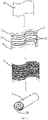
FIG. 1 is a fabrication flowchart of a heating assembly according to some embodiments of the present invention; -
FIG. 2 is a schematic structural diagram of a heating circuit of a heating element according to some embodiments of the present invention; and -
FIG. 3 is a schematic structural diagram of a conductive circuit of a heating element according to some embodiments of the present invention. - To provide a clearer understanding of the technical features, objectives, and effects of the present invention, specific implementations of the present invention are described with reference to the accompanying drawings.
- As shown in
FIG. 1 to FIG. 3 , the flexible heating assembly in some embodiments of the present invention includes aflexible heating element 1 and an aerosol-generating substrate 2 coated on a side surface of theheating element 1. Theflexible heating element 1 includes a sheet-shapedflexible substrate 11, at least oneheating circuit 12 disposed on thesubstrate 11,conductive circuits 13 disposed on thesubstrate 11 and respectively connected to two ends of theheating circuit 12, electrode leads 14 respectively connected to theconductive circuits 13, and a flexible protective film covering the at least oneheating circuit 12. - When the
flexible heating element 1 is in use, an aerosol-generating substrate 2 added with a viscous substance (for example, reconstituted tobacco added with a viscous substance) can be coated on the side surface of theheating element 1 on which theheating circuit 12 is disposed, and the thickness of the aerosol-generating substrate 2 may be from 0.5 nm to 1 mm. Then theheating element 1 covered with the aerosol-generating substrate 2 is wound into a shape of a spiral cylinder to form a flexible heating assembly. This structure can increase the direct contact area and the heating area between theheating element 1 and the aerosol-generating substrate 2. Theheating element 1 can heat the aerosol-generating substrate 2 in all directions, and the aerosol-generating substrate 2 is heated faster and more uniformly, which reduces a preheating time, so that theheating element 1 can reach an instant inhaling mode, which has advantages such as fast vapor generation and a large amount of vapor. - Two or
more heating circuits 12 may be disposed on thesubstrate 11 of theheating element 1, and two ends of eachheating circuit 12 are respectively electrically connected to the electrode leads 14. The aerosol-generating substrate 2 can be heated by segments, so that the aerosol-generating substrate 2 can be heated sequentially by segments instead of being heated at one time, which improves the utilization of the aerosol-generating substrate and the inhaling convenience, and simultaneously can avoid a burnt smell produced by over-baking the baked aerosol-generating substrate, thereby improving the inhaling taste. Eachheating circuit 12 can be distributed in the axial direction of thesubstrate 11 after winding (the width direction of thesubstrate 11 in this embodiment), or can be distributed in a circumferential direction after winding (a length direction of thesubstrate 11 in this embodiment), or can be distributed in the axial and circumferential directions of thesubstrate 11 after winding. - To ensure the uniformity of the temperature field in a heating region, the
heating circuit 12 needs to be formed into a proper pattern, such as an S shape, a spiral shape, a wave shape, or the like. A pattern of theheating circuit 12 may be prepared by using a mask method or an ion etching method. The mask method is to form the pattern of theheating circuit 12 on thesubstrate 11 after sputtering theheating circuit 12 by masking a non-patterned position on thesubstrate 11. The ion etching method is to first plate theheating circuit 12 on a whole surface of thesubstrate 11, after photoresist is applied for exposure and curing, ion-etch the exposed photoresist and a region of theheating circuit 12, and then remove the unexposed photoresist to form a required pattern of theheating circuit 12. A pattern of theconductive circuit 13 may also be prepared by using the mask method or the ion etching method. - The
heating circuit 12, theconductive circuit 13, and the protective film can be all formed by magnetron sputtering coating. A manner of magnetron sputtering can reduce the overall thickness of theheating element 1, and simultaneously can improve the resistance consistency of the pattern of theheating circuit 12 and reduce a fluctuation range of TCR, which is more conducive to precise temperature control of the heating field. - The
substrate 11 can be a transparent or non-transparent flexible insulating sheet with high temperature resistance, corrosion resistance, and a stable material structure, and provide a carrier for the sputteredheating circuit 12 and theconductive circuit 13. In some embodiments, thesubstrate 11 may be made of at least one of high-temperature-resistant flexible insulating polyimide film (namely, PI film), aluminosilicate fiber paper, and flexible ceramic sheet prepared by casting. The thickness of thesubstrate 11 may be from 0.5 mm to 2 mm. - A function of the
heating circuit 12 is to stably generate heat after being energized, and to heat an aerosol-generating substrate, which can usually be made of a metal material with high resistivity (that is, high resistance) and more generated heat. In some embodiments, theheating circuit 12 may be formed by sputtering a metal or an alloy material, such as Pt, AgPd, NiCr, or NiCrAlY, on the transition layer after direct current or radio frequency magnetron sputtering is performed on the transition layer, and the thickness of theheating circuit 12 may be from 1 µm to 3.5 µm. - In some embodiments, the
heating circuit 12 includes atransition layer 121 disposed on thesubstrate 11 and aheating layer 122 disposed on thetransition layer 121. Thetransition layer 121 mainly enhances the bonding force between theheating layer 122 and thesubstrate 11, increases the structural stability, prevents separation, and improves the bonding stability between a film and a substrate when the heating element generates heat circularly. Thetransition layer 121 may be made of an alloy that forms a stable chemical bond with both thesubstrate 11 and theheating layer 122, for example, thetransition layer 121 may be made of at least one of Cr, ZrNi, and TiN. Theheating layer 122 should be made of a material with high resistivity, more generated heat, stable material structure performance after high temperature heating, and good high temperature oxidation resistance and corrosion resistance, for example, a precious metal material such as Pt, or a precious metal alloy material such as AuPd, PtRu, PtRh, or AgPd, or a high-temperature-resistant alloy material such as NiCr or NiCrAlY. - One end of the
conductive circuit 13 is connected to theheating circuit 12, and the other end is connected to theelectrode lead 14 to be welded with theelectrode lead 14 and supply power to theheating circuit 12. Theconductive circuit 13 has low resistivity (that is, low resistance), and generates few heat. In some embodiments, theconductive circuit 13 may be formed by sputtering a thin film, such as an Ag thin film, an Au thin film, or a Cu thin film after performing direct current or radio frequency sputtering pure Ti or Pure Ni, or plating the pure Ti and the pure Ni on the substrate. The thickness of theconductive circuit 13 may be equal to or slightly higher than the thickness of theheating circuit 12. In some embodiments, the thickness of theconductive circuit 13 may be from 1 µm to 5 µm. - In some embodiments, the
conductive circuit 13 may include abottom layer 131 disposed on thesubstrate 11, anintermediate buffer layer 132 disposed on thebottom layer 131, and aconductive layer 133 disposed on theintermediate buffer layer 132. Thebottom layer 131 and theintermediate buffer layer 132 may respectively be made of at least one of pure Ti and pure Ni. Thebottom layer 131 and theintermediate buffer layer 132 are respectively formed by coating, which helps form a certain thickness, and can further increase the structural stability and prevent separation. Theconductive layer 133 may be made of a metal material with good stability and conductivity, for example, theconductive layer 133 may be made of at least one of Au, Ag, Ni, and Cu. Generally, silver or copper may be used due to low costs. - A function of the protective film is to reduce the erosive effect of oxygen and impurities on the
heating circuit 12, prevent theheating circuit 12 from reacting with the aerosol-generating substrate 2 during heating, and reduce an impact of the accumulation of soot on the inhaling taste. Part regions of theconductive circuit 13 and regions on thesubstrate 11 where theconductive circuit 13 and theheating circuit 12 are not disposed may also be covered with a protective film. Because theconductive circuit 13 needs to be welded with theelectrode lead 14, a region where theconductive circuit 13 is welded with theelectrode lead 14 is not covered by the protective film. In some embodiments, the protective film may be a ceramic material with good flexibility, a thermal expansion coefficient adapting to thesubstrate 11, good high temperature stability, easy to clean, and good corrosion resistance, for example, a material such as casting sheet or Si3N4, or an oxide material such as ZrO2, Al2O3, or SiO2. The protective film may be prepared by at least one of ZrO2 composite film, Al2O3 composite film, SiO2 composite film, and Si3N4 composite film prepared through direct current or radio frequency magnetron sputtering, and the thickness of the protective film is from 100 nm to 1000 nm. - The present invention further provides a fabrication method for a flexible heating element, including the following steps:
- S1: Processing before coating:
a sheet-shapeflexible substrate 11 is provided, after thesubstrate 11 is wiped and cleaned with alcohol, thesubstrate 11 is placed into a coating machine cavity, the coating machine cavity is vacuumized and preheated, and the surface of thesubstrate 11 is ion-cleaned. - S2: Formation of the heating circuit 12:
- Magnetron sputtering is performed on the
substrate 11 to form theheating circuit 12. - Specifically, step S2 may include:
- introducing argon until the working air pressure in the cavity reaches 0.5 Pa, turning on a Cr target power supply, and coating a film on the
substrate 11 for 5 minutes to 15 minutes at a power density of from 6 W/cm2 to 8 W/cm2 and at a room temperature to form thetransition layer 121 with a thickness of from 10 nm to 200 nm; and - then turning off the Cr target power supply, turning on a NiCr target power supply, and coating a film on the
transition layer 121 for 60 minutes to 120 minutes at a power density of from 6 W/cm2 to 8 W/cm2 and at a room temperature to form theheating layer 122 with a thickness of from 1 µm to 2.5 µm. - S3: Formation of the conductive circuit 13:
Magnetron sputtering is performed on thesubstrate 11 to form theconductive circuit 13. - Specifically, step S3 may include:
- introducing argon until a working air pressure in the cavity is 0.5 Pa, turning on of a Titanium target power supply, and coating a film on the
substrate 11 for 5 minutes to 10 minutes at a power density of from 6 W/cm2 to 8 W/cm2 and at a room temperature to form thebottom layer 131; turning off the Titanium target power supply; - then turning on the Titanium target power supply, and coating a
film 131 on the bottom layer for 10 minutes to 30 minutes at the power density of from 6 W/cm2 to 8 W/cm2 and at a room temperature to form theintermediate buffer layer 132; turning off the power supply of the Titanium target; - then turning on a silver target power supply, and coating a film on the
intermediate buffer layer 132 for 30 minutes to 120 minutes at a power density of from 4 W/cm2 to 8 W/cm2 and at a room temperature to form theconductive layer 133; and - soldering an
electrode lead 14 on theconductive layer 133 to form a conductive electrode. - S4: Formation of the protective film:
- Argon and oxygen in a ratio of 1:1 are introduced until the working air pressure in the cavity reaches 0.4 Pa, and sputtering is performed at a sputtering power density of a direct current SiO2 target power supply between 2 W/cm2 and 6 W/cm2 and at a temperature between room temperature and 500°C to form the protective film with a thickness of from 100 nm to 1000 nm.
- The present invention further provides an aerosol generator, including a cavity for accommodating a heating assembly and a heating assembly disposed in the cavity, wherein the
heating element 1 of the heating assembly, after being energized and heated up, bakes and heats the aerosol-generating substrate 2 for the user to inhale. - It can be understood that the foregoing technical features can be used in any combination without limitation.
- While the invention has been illustrated and described in detail in the drawings and foregoing description, such illustration and description are to be considered illustrative or exemplary and not restrictive. It will be understood that changes and modifications may be made by those of ordinary skill within the scope of the following claims. In particular, the present invention covers further embodiments with any combination of features from different embodiments described above and below. Additionally, statements made herein characterizing the invention refer to an embodiment of the invention and not necessarily all embodiments.
Claims (20)
- A flexible heating element, characterized by comprising:a sheet-shaped flexible substrate (11);at least one heating circuit (12) disposed on the substrate (11);conductive circuits (13) disposed on the substrate (11) and respectively connected to two ends of each heating circuit (12), anda flexible protective film covering the at least one heating circuit (12).
- The heating element of claim 1, wherein the at least one heating circuit (12), the conductive circuit (13), and the protective film are all formed by magnetron sputtering coating.
- The heating element of claim 1, wherein the substrate (11) is made of at least one of aluminosilicate fiber paper, PI film, and casting ceramic sheet.
- The heating element of claim 1, wherein the protective film is made of at least one of casting sheet, nitride ceramic material, and oxide ceramic material, and
wherein the thermal expansion coefficient of the protective film adapts to the thermal expansion coefficient of the substrate (11). - The heating element of claim 1, wherein the protective film is prepared by at least one of ZrO2 composite film, Al2O3 composite film, SiO2 composite film, and Si3N4 composite film prepared through direct current magnetron sputtering or radio frequency magnetron sputtering, and
wherein the thickness of the protective film is from 100 nm to 1000 nm. - The heating element of claim 1, wherein the thickness of the heating circuit (12) is from 1 µm to 3.5 µm, and the thickness of the conductive circuits (13) is from 1 µm to 5 µm.
- The heating element of claim 1, further comprising:
electrode leads (14) respectively connected to the conductive circuits (13). - The heating element according to any of claims 1 to 7, wherein the heating circuit (12) comprises a transition layer (121) disposed on the substrate (11) and a heating layer (122) disposed on the transition layer (121).
- The heating element of claim 8, wherein the transition layer (121) is made of at least one of Cr, ZrNi, and TiN, and
wherein the heating layer (122) is made of at least one of Pt, AgPd, AuPd, PtRu, PtRh, NiCr, and NiCrAlY. - The heating element according to any of claims 1 to 7, wherein the conductive circuits (13) comprise a bottom layer (131) disposed on the substrate (11), an intermediate buffer layer (132) disposed on the bottom layer (131), and a conductive layer (133) disposed on the intermediate buffer layer (132).
- The heating element of claim 10, wherein the bottom layer (131) is made of at least one of pure Ti, and pure Ni,
wherein the intermediate buffer layer (132) is made of at least one of pure Ti and pure Ni, and wherein the conductive layer (133) is made of at least one of Au, Ag, and Cu. - A method for fabricating a flexible heating element, comprising:S1: providing a sheet-shaped flexible substrate (11), and placing the substrate (11) into a coating machine cavity;S2: performing magnetron sputtering on the substrate (11) to form at least one heating circuit (12);S3: performing magnetron sputtering on the ubstrate (11) to form a conductive circuit (13); andS4: performing magnetron sputtering on the at least one heating circuit (12) to form a protective film.
- The method of claim 12, wherein in S1, wiping and cleaning the substrate (11) with alcohol,placing the substrate (11) in a coating machine cavity,vacuuming and preheating the coating machine cavity, andion-cleaning the surface of the substrate (11); andin S4, introducing argon and oxygen in a ratio of 1:1 into the cavity until the working air pressure therein reaches 0.4 Pa;turning on a power supply for a SiO2 target, a ZrO2 target, an Al2O3 target, or a Si3N4 target; andperforming magnetron sputtering at a power density between 2 W/cm2 and 6 W/cm2 and at a temperature between room temperature and 500°C to form the protective film with a thickness between 100 nm and 1000 nm.
- The method of claim 12, wherein S2 comprises:performing magnetron sputtering on the substrate (11) to form a transition layer (121); andperforming magnetron sputtering on the transition layer (121) to form a heating layer (122).
- The method of claim 14, wherein in S2, introducing argon into thecavity until the working air pressure therein reaches 0.5 Pa,turning on a power supply for a Cr target, a ZrNi target, or a TiN targe,coating a film on the substrate (11) for 5 minutes to 15 minutes at a power density between 6 W/cm2 and 8 W/cm2 and at room temperature to form the transition layer (121) with a thickness between 10 nm and 200 nm, andturning off the power supply for the Cr target, the ZrNi target, or the TiN target, turning on a power supply for a NiCr target, a NiCrAlY target, a Pt target, an AgPd target, an AuPd target, a PtRu target, or a PtRh target, andcoating a film on the transition layer (121) for 60 minutes to 120 minutes at a power density between 6 W/cm2 and 8 W/cm2 and at room temperature to form the heating layer (122) with a thickness between 1 µm and 2.5 µm.
- The method of claim 12, wherein S3 comprises:performing magnetron sputtering on the substrate (11) to form a bottom layer (131);performing magnetron sputtering on the bottom layer (131) to form an intermediate buffer layer (132);performing magnetron sputtering on the intermediate buffer layer (132) to form a conductive layer (133); andsoldering an electrode lead (14) on the conductive layer (133) to form a conductive electrode.
- The method of claim 16, wherein in S2, introducing argon into the cavity until the working air pressure therein reaches 0.5 Pa,turning on a power supply for a Titanium target or a Nickel target,coating a film on the substrate (11) for 5 minutes to 10 minutes at a power density between 6 W/cm2 and 8 W/cm2 and at room temperature to form the bottom layer (131),turning off the power supply for the Titanium target or the Nickel target,turning on a power supply for a Nickel target or a Titanium target.coating a film (131) on the bottom layer for 10 minutes to 30 minutes at a power density between 6 W/cm2 and 8 W/cm2 and at room temperature to form the intermediate buffer layer (132),turning off the power supply for the Nickel target or the Titanium target,turning on a power supply for a silver target, a copper target, or a gold target, and coating a film on the intermediate buffer layer (132) for 30 minutes to 120 minutes at a power density between 4 W/cm2 and 8 W/cm2 at room temperature to form the conductive layer (133).
- A flexible heating assembly, wherein the heating assembly is in spiral cylindrical shape, and the heating assembly comprises the heating element of any one of claims 1 to 11; and an aerosol-generating substrate coated on the side surface of the heating element, on which the at least one heating circuit (12) is disposed;
- The heating assembly of claim 18, wherein the aerosol-generating substrate is an aerosol-generating substrate to which a viscous substance is added, and wherein the thickness of the aerosol-generating substrate is from 0.5 mm to 1 mm.
- An aerosol generator, characterized by comprising:
the heating element of any one of claims 1 to 11.
Applications Claiming Priority (2)
| Application Number | Priority Date | Filing Date | Title |
|---|---|---|---|
| CN201911327773.XA CN111053298B (en) | 2019-12-20 | 2019-12-20 | Flexible heating element and manufacturing method thereof, flexible heating assembly and aerosol generator |
| PCT/CN2020/120691 WO2021120802A1 (en) | 2019-12-20 | 2020-10-13 | Flexible heating element, fabrication method therefor, flexible heating assembly thereof, and aerosol generator |
Publications (2)
| Publication Number | Publication Date |
|---|---|
| EP4079172A1 true EP4079172A1 (en) | 2022-10-26 |
| EP4079172A4 EP4079172A4 (en) | 2023-10-25 |
Family
ID=70302605
Family Applications (1)
| Application Number | Title | Priority Date | Filing Date |
|---|---|---|---|
| EP20902306.8A Pending EP4079172A4 (en) | 2019-12-20 | 2020-10-13 | FLEXIBLE HEATING ELEMENT, METHOD FOR MANUFACTURING ITS, ASSOCIATED FLEXIBLE HEATING ASSEMBLY, AND AEROSOL GENERATOR |
Country Status (4)
| Country | Link |
|---|---|
| US (1) | US20220295602A1 (en) |
| EP (1) | EP4079172A4 (en) |
| CN (1) | CN111053298B (en) |
| WO (1) | WO2021120802A1 (en) |
Families Citing this family (12)
| Publication number | Priority date | Publication date | Assignee | Title |
|---|---|---|---|---|
| GB201805510D0 (en) * | 2018-04-04 | 2018-05-16 | Nicoventures Trading Ltd | Vapour provision systems |
| CN112251723B (en) * | 2019-07-04 | 2022-05-03 | 深圳麦克韦尔科技有限公司 | Heating element, preparation method thereof and electronic smoking set |
| CN111053298B (en) * | 2019-12-20 | 2022-03-15 | 深圳麦克韦尔科技有限公司 | Flexible heating element and manufacturing method thereof, flexible heating assembly and aerosol generator |
| CN111418906A (en) * | 2020-03-19 | 2020-07-17 | 云南中烟工业有限责任公司 | A kind of flexible heating element, its preparation method and use |
| JP7641362B2 (en) | 2020-10-28 | 2025-03-06 | フィリップ・モーリス・プロダクツ・ソシエテ・アノニム | Heater tubes with thermal and electrical insulation |
| CN116058551A (en) * | 2021-11-03 | 2023-05-05 | 深圳市合元科技有限公司 | Heating element, manufacturing method of heating element, and aerosol generating device |
| CN220800051U (en) | 2021-12-30 | 2024-04-19 | 深圳麦克韦尔科技有限公司 | Heating component, atomizer and electronic atomization device |
| EP4298932B1 (en) * | 2022-05-13 | 2024-09-04 | Shenzhen Smoore Technology Limited | Heat generating element, atomizing assembly, and electronic atomizing device |
| CN114831358B (en) * | 2022-05-20 | 2025-08-19 | 深圳市赛尔美电子科技有限公司 | Heating component of atomization device and preparation method thereof |
| CN115024529A (en) * | 2022-06-06 | 2022-09-09 | 深圳市吉迩科技有限公司 | Heating element and preparation method thereof |
| CN115349673A (en) * | 2022-08-08 | 2022-11-18 | 海南摩尔兄弟科技有限公司 | Aerosol generating device and its heating components |
| CN117547067A (en) * | 2023-11-10 | 2024-02-13 | 谦逊恩典有限公司 | Atomizer component and manufacturing method thereof, atomizer and aerosol generating device |
Family Cites Families (55)
| Publication number | Priority date | Publication date | Assignee | Title |
|---|---|---|---|---|
| US4449039A (en) * | 1981-09-14 | 1984-05-15 | Nippondenso Co., Ltd. | Ceramic heater |
| US4468557A (en) * | 1983-02-03 | 1984-08-28 | Bylin Heating Systems, Inc. | Conformable electric heating apparatus |
| JPS60193288A (en) * | 1984-03-15 | 1985-10-01 | 徳丸 千之助 | Sheetlike heater |
| US4797536A (en) * | 1986-03-31 | 1989-01-10 | Electrofilm, Inc. | Temperature control apparatus for a waterbed |
| US4926106A (en) * | 1986-07-22 | 1990-05-15 | Tanis Peter G | Aircraft battery charging device |
| US5150722A (en) * | 1989-07-12 | 1992-09-29 | International Flavors & Fragrances Inc. | Multi-layer scent emitting article and device adapted to employ same |
| US5408574A (en) * | 1989-12-01 | 1995-04-18 | Philip Morris Incorporated | Flat ceramic heater having discrete heating zones |
| US5114754A (en) * | 1991-01-14 | 1992-05-19 | International Business Machines Corporation | Passivation of metal in metal/polyimide structures |
| US5369723A (en) * | 1992-09-11 | 1994-11-29 | Philip Morris Incorporated | Tobacco flavor unit for electrical smoking article comprising fibrous mat |
| US5498855A (en) * | 1992-09-11 | 1996-03-12 | Philip Morris Incorporated | Electrically powered ceramic composite heater |
| US5472539A (en) * | 1994-06-06 | 1995-12-05 | General Electric Company | Methods for forming and positioning moldable permanent magnets on electromagnetically actuated microfabricated components |
| JP3228924B2 (en) * | 2000-01-21 | 2001-11-12 | イビデン株式会社 | Ceramic heater for semiconductor manufacturing and inspection equipment |
| US6964201B2 (en) * | 2003-02-25 | 2005-11-15 | Palo Alto Research Center Incorporated | Large dimension, flexible piezoelectric ceramic tapes |
| JP4569077B2 (en) * | 2003-06-05 | 2010-10-27 | 住友電気工業株式会社 | HOLDER FOR SEMICONDUCTOR OR LIQUID CRYSTAL MANUFACTURING DEVICE AND SEMICONDUCTOR OR LIQUID CRYSTAL MANUFACTURING DEVICE WITH THE SAME |
| JP2005149751A (en) * | 2003-11-11 | 2005-06-09 | Olympus Corp | Heater element |
| US20060035413A1 (en) * | 2004-01-13 | 2006-02-16 | Cookson Electronics, Inc. | Thermal protection for electronic components during processing |
| US20050151555A1 (en) * | 2004-01-13 | 2005-07-14 | Cookson Electronics, Inc. | Cooling devices and methods of using them |
| SG119230A1 (en) * | 2004-07-29 | 2006-02-28 | Micron Technology Inc | Interposer including at least one passive element at least partially defined by a recess formed therein method of manufacture system including same and wafer-scale interposer |
| US7687724B2 (en) * | 2005-01-10 | 2010-03-30 | Endicott Interconnect Technologies, Inc. | Circuitized substrate with internal resistor, method of making said circuitized substrate, and electrical assembly utilizing said circuitized substrate |
| US9390790B2 (en) * | 2005-04-05 | 2016-07-12 | Nantero Inc. | Carbon based nonvolatile cross point memory incorporating carbon based diode select devices and MOSFET select devices for memory and logic applications |
| US20090162651A1 (en) * | 2005-08-02 | 2009-06-25 | World Properties, Inc. | Silicone compositions, methods of manufacture, and articles formed therefrom |
| CN100517517C (en) * | 2006-11-22 | 2009-07-22 | 鲁东大学 | A kind of flexible composite transparent conductive film and preparation method thereof |
| US8747599B2 (en) * | 2008-05-29 | 2014-06-10 | Chidella Krishna Sastry | Process for making self-patterning substrates and the product thereof |
| US20100000762A1 (en) * | 2008-07-02 | 2010-01-07 | Applied Nanotech Holdings, Inc. | Metallic pastes and inks |
| EP2416400A1 (en) * | 2009-03-31 | 2012-02-08 | Nippon Steel Corporation | Material for metallic outer case for secondary battery utilizing non-aqueous electrolyte, metallic outer case, secondary battery, and process for production of material for metallic outer case |
| EP2319334A1 (en) * | 2009-10-27 | 2011-05-11 | Philip Morris Products S.A. | A smoking system having a liquid storage portion |
| EP2316286A1 (en) * | 2009-10-29 | 2011-05-04 | Philip Morris Products S.A. | An electrically heated smoking system with improved heater |
| EP2340729A1 (en) * | 2009-12-30 | 2011-07-06 | Philip Morris Products S.A. | An improved heater for an electrically heated aerosol generating system |
| US10136672B2 (en) * | 2010-05-15 | 2018-11-27 | Rai Strategic Holdings, Inc. | Solderless directly written heating elements |
| US20110290304A1 (en) * | 2010-05-27 | 2011-12-01 | Palo Alto Research Center Incorporated | Photovoltaic modules on a textile substrate |
| JP2012134132A (en) * | 2010-12-02 | 2012-07-12 | Ube Ind Ltd | Flexible heater and method of manufacturing the same |
| US20120305022A1 (en) * | 2011-06-02 | 2012-12-06 | William Robert Bickford | Cosmetic Applicator Head With Dynamically Adjustable Durometer |
| US20130105806A1 (en) * | 2011-11-01 | 2013-05-02 | Guojun Liu | Structures incorporating silicon nanoparticle inks, densified silicon materials from nanoparticle silicon deposits and corresponding methods |
| CN103890700B (en) * | 2011-11-07 | 2018-10-12 | 王子控股株式会社 | The display device of capacitor formula touch panel, capacitive touch panels |
| US10249684B2 (en) * | 2012-12-17 | 2019-04-02 | Nantero, Inc. | Resistive change elements incorporating carbon based diode select devices |
| US8941969B2 (en) * | 2012-12-21 | 2015-01-27 | Applied Materials, Inc. | Single-body electrostatic chuck |
| US20160249413A1 (en) * | 2015-02-23 | 2016-08-25 | Electronics And Telecommunications Research Institute | Transparent planar heater |
| TWI691399B (en) * | 2015-03-31 | 2020-04-21 | 美商羅傑斯公司 | Substrates, laminates, and components for flexible heaters, flexible heaters, and methods of manufacturing the same |
| GB201508670D0 (en) * | 2015-05-20 | 2015-07-01 | British American Tobacco Co | Aerosol generating material and devices including the same |
| US11445747B2 (en) * | 2015-10-22 | 2022-09-20 | Philip Morris Products Sa. | Aerosol-generating system |
| CN106028486A (en) * | 2016-05-17 | 2016-10-12 | 上海科比斯光学科技有限公司 | Composite conductive film and preparation method and application thereof |
| US10085485B2 (en) * | 2016-07-06 | 2018-10-02 | Rai Strategic Holdings, Inc. | Aerosol delivery device with a reservoir housing and a vaporizer assembly |
| CN106072775A (en) * | 2016-07-27 | 2016-11-09 | 杭州森翼科技有限公司 | A kind of electronic cigarette composite heating silk |
| US9993027B1 (en) * | 2016-12-06 | 2018-06-12 | Funai Electric Co., Ltd. | Heater element for a vaporization device |
| CN106579564B (en) * | 2016-12-23 | 2020-03-31 | 湘潭大学 | Porous heating film and preparation method thereof |
| CN206923677U (en) * | 2017-04-25 | 2018-01-26 | 湖南中烟工业有限责任公司 | Flexible heating element, jettisonable cigarette bullet and low temperature smoking set |
| CN207754542U (en) * | 2017-10-30 | 2018-08-24 | 深圳市合元科技有限公司 | The apparatus for aerosol creation of adjustable heating region |
| CN207869432U (en) * | 2018-03-07 | 2018-09-14 | 东莞市国研电热材料有限公司 | A multi-temperature zone ceramic heating element |
| CN108513378A (en) * | 2018-03-14 | 2018-09-07 | 电子科技大学 | A kind of thin resistive heater and preparation method thereof |
| CN209218417U (en) * | 2018-08-22 | 2019-08-06 | 东莞市国研电热材料有限公司 | A multi-layer heating ceramic heating element for electronic cigarettes |
| CN209376696U (en) * | 2018-11-29 | 2019-09-13 | 深圳市合元科技有限公司 | Electronic smoke atomizer and electronic cigarette comprising the electronic smoke atomizer |
| CN109527660B (en) * | 2019-01-18 | 2024-08-20 | 无锡杰程光电有限公司 | Manufacturing method of electronic cigarette film heating sheet |
| CN209769004U (en) * | 2019-03-21 | 2019-12-13 | 云南中烟工业有限责任公司 | self-heating type heating non-combustible cigarette with flexible heating material |
| CN110495642A (en) * | 2019-09-11 | 2019-11-26 | 深圳市你我网络科技有限公司 | Heat not burner and its heating component |
| CN111053298B (en) * | 2019-12-20 | 2022-03-15 | 深圳麦克韦尔科技有限公司 | Flexible heating element and manufacturing method thereof, flexible heating assembly and aerosol generator |
-
2019
- 2019-12-20 CN CN201911327773.XA patent/CN111053298B/en active Active
-
2020
- 2020-10-13 WO PCT/CN2020/120691 patent/WO2021120802A1/en not_active Ceased
- 2020-10-13 EP EP20902306.8A patent/EP4079172A4/en active Pending
-
2022
- 2022-06-01 US US17/829,646 patent/US20220295602A1/en active Pending
Also Published As
| Publication number | Publication date |
|---|---|
| WO2021120802A1 (en) | 2021-06-24 |
| CN111053298A (en) | 2020-04-24 |
| CN111053298B (en) | 2022-03-15 |
| US20220295602A1 (en) | 2022-09-15 |
| EP4079172A4 (en) | 2023-10-25 |
Similar Documents
| Publication | Publication Date | Title |
|---|---|---|
| US20220295602A1 (en) | Flexible heating element, fabrication method therefor, flexible heating assembly thereof, and aerosol generator | |
| US12484621B2 (en) | Electronic baking cigarette device and heating apparatus thereof | |
| CN109527660B (en) | Manufacturing method of electronic cigarette film heating sheet | |
| EP4136990B1 (en) | Heater and smoking set comprising the heater | |
| EP3815559B1 (en) | Aerosol generating device and heating assembly thereof | |
| CN104886775B (en) | Electrically heated smoking system for receiving an aerosol-forming substrate | |
| WO2021129677A1 (en) | Heater and cigarette utensil having same | |
| US12458073B2 (en) | Vapor generation device and infrared emitter | |
| KR102865696B1 (en) | A heater and a smoking set including the heater | |
| CN112251723B (en) | Heating element, preparation method thereof and electronic smoking set | |
| CN210988241U (en) | Electronic cigarette film heating sheet | |
| CN211065053U (en) | Electron cigarette heater | |
| WO2020244682A1 (en) | Heating element and atomization device | |
| EP4329424A1 (en) | Aerosol-forming apparatus and heating assembly | |
| JP2024545030A (en) | Heating chamber assembly for an aerosol generating device - Patent Application 20070123633 | |
| CN211960905U (en) | Embedded heating cigarette heating element | |
| CN219068401U (en) | Heating device and electronic cigarette | |
| CN224069736U (en) | Gas mist generating device and heater for gas mist generating device | |
| CN220274930U (en) | Needle type heating body and aerosol generating device | |
| KR20250121567A (en) | Heater and manufacturing method thereof, aerosol generating device | |
| CN118766168A (en) | Needle-type heating body and aerosol generating device | |
| CN222941805U (en) | Aerosol generating device and heater for aerosol generating device | |
| CN219982113U (en) | Heating components and aerosol generating devices | |
| US20250107568A1 (en) | Aerosol generating apparatus and heater for aerosol generating apparatus | |
| CN118766166A (en) | A HNB heating body and aerosol generating device |
Legal Events
| Date | Code | Title | Description |
|---|---|---|---|
| STAA | Information on the status of an ep patent application or granted ep patent |
Free format text: STATUS: THE INTERNATIONAL PUBLICATION HAS BEEN MADE |
|
| PUAI | Public reference made under article 153(3) epc to a published international application that has entered the european phase |
Free format text: ORIGINAL CODE: 0009012 |
|
| STAA | Information on the status of an ep patent application or granted ep patent |
Free format text: STATUS: REQUEST FOR EXAMINATION WAS MADE |
|
| 17P | Request for examination filed |
Effective date: 20220704 |
|
| AK | Designated contracting states |
Kind code of ref document: A1 Designated state(s): AL AT BE BG CH CY CZ DE DK EE ES FI FR GB GR HR HU IE IS IT LI LT LU LV MC MK MT NL NO PL PT RO RS SE SI SK SM TR |
|
| DAV | Request for validation of the european patent (deleted) | ||
| DAX | Request for extension of the european patent (deleted) | ||
| RIC1 | Information provided on ipc code assigned before grant |
Ipc: A24F 40/20 20200101ALN20230602BHEP Ipc: H05B 3/42 20060101ALI20230602BHEP Ipc: H05B 3/36 20060101ALI20230602BHEP Ipc: H05B 3/34 20060101ALI20230602BHEP Ipc: H05B 3/10 20060101ALI20230602BHEP Ipc: A24F 40/70 20200101ALI20230602BHEP Ipc: A24F 40/46 20200101AFI20230602BHEP |
|
| A4 | Supplementary search report drawn up and despatched |
Effective date: 20230921 |
|
| RIC1 | Information provided on ipc code assigned before grant |
Ipc: A24F 40/20 20200101ALN20230915BHEP Ipc: H05B 3/42 20060101ALI20230915BHEP Ipc: H05B 3/36 20060101ALI20230915BHEP Ipc: H05B 3/34 20060101ALI20230915BHEP Ipc: H05B 3/10 20060101ALI20230915BHEP Ipc: A24F 40/70 20200101ALI20230915BHEP Ipc: A24F 40/46 20200101AFI20230915BHEP |
|
| RAP3 | Party data changed (applicant data changed or rights of an application transferred) |
Owner name: SHENZHEN SMOORE TECHNOLOGY LIMITED |
|
| RAP3 | Party data changed (applicant data changed or rights of an application transferred) |
Owner name: SHENZHEN SMOORE TECHNOLOGY LIMITED |
|
| STAA | Information on the status of an ep patent application or granted ep patent |
Free format text: STATUS: EXAMINATION IS IN PROGRESS |
|
| 17Q | First examination report despatched |
Effective date: 20250707 |
|
| GRAP | Despatch of communication of intention to grant a patent |
Free format text: ORIGINAL CODE: EPIDOSNIGR1 |
|
| STAA | Information on the status of an ep patent application or granted ep patent |
Free format text: STATUS: GRANT OF PATENT IS INTENDED |
|
| RIC1 | Information provided on ipc code assigned before grant |
Ipc: A24F 40/46 20200101AFI20260408BHEP Ipc: A24F 40/70 20200101ALI20260408BHEP Ipc: H05B 3/10 20060101ALI20260408BHEP Ipc: H05B 3/34 20060101ALI20260408BHEP Ipc: H05B 3/36 20060101ALI20260408BHEP Ipc: H05B 3/42 20060101ALI20260408BHEP Ipc: A24F 40/20 20200101ALN20260408BHEP |