EP4078227B1 - Doppler-messverfahren für multistatische radarvorrichtung, radarvorrichtung zur durchführung eines solchen verfahrens - Google Patents
Doppler-messverfahren für multistatische radarvorrichtung, radarvorrichtung zur durchführung eines solchen verfahrens Download PDFInfo
- Publication number
- EP4078227B1 EP4078227B1 EP20812061.8A EP20812061A EP4078227B1 EP 4078227 B1 EP4078227 B1 EP 4078227B1 EP 20812061 A EP20812061 A EP 20812061A EP 4078227 B1 EP4078227 B1 EP 4078227B1
- Authority
- EP
- European Patent Office
- Prior art keywords
- radar
- frequency
- transmission
- reception
- target
- Prior art date
- Legal status (The legal status is an assumption and is not a legal conclusion. Google has not performed a legal analysis and makes no representation as to the accuracy of the status listed.)
- Active
Links
- 238000000034 method Methods 0.000 title claims description 17
- 238000000691 measurement method Methods 0.000 title 1
- 230000005540 biological transmission Effects 0.000 claims description 31
- 230000017105 transposition Effects 0.000 claims description 7
- 101100412102 Haemophilus influenzae (strain ATCC 51907 / DSM 11121 / KW20 / Rd) rec2 gene Proteins 0.000 description 9
- 101100356020 Haemophilus influenzae (strain ATCC 51907 / DSM 11121 / KW20 / Rd) recA gene Proteins 0.000 description 9
- 239000000243 solution Substances 0.000 description 9
- 101100042680 Mus musculus Slc7a1 gene Proteins 0.000 description 8
- 238000005259 measurement Methods 0.000 description 7
- 239000000969 carrier Substances 0.000 description 6
- 230000010287 polarization Effects 0.000 description 6
- 240000008042 Zea mays Species 0.000 description 4
- 238000001514 detection method Methods 0.000 description 2
- 238000010586 diagram Methods 0.000 description 2
- 230000000694 effects Effects 0.000 description 2
- 238000005070 sampling Methods 0.000 description 2
- 229920006395 saturated elastomer Polymers 0.000 description 2
- 238000000926 separation method Methods 0.000 description 2
- 238000000638 solvent extraction Methods 0.000 description 2
- AETVBWZVKDOWHH-UHFFFAOYSA-N 2-[4-[2-(2,3-dihydro-1H-inden-2-ylamino)pyrimidin-5-yl]-3-(1-ethylazetidin-3-yl)oxypyrazol-1-yl]-1-(2,4,6,7-tetrahydrotriazolo[4,5-c]pyridin-5-yl)ethanone Chemical compound C1C(CC2=CC=CC=C12)NC1=NC=C(C=N1)C=1C(=NN(C=1)CC(=O)N1CC2=C(CC1)NN=N2)OC1CN(C1)CC AETVBWZVKDOWHH-UHFFFAOYSA-N 0.000 description 1
- 239000000654 additive Substances 0.000 description 1
- 230000000996 additive effect Effects 0.000 description 1
- 230000003321 amplification Effects 0.000 description 1
- 230000001427 coherent effect Effects 0.000 description 1
- 230000007274 generation of a signal involved in cell-cell signaling Effects 0.000 description 1
- 230000003993 interaction Effects 0.000 description 1
- 230000004807 localization Effects 0.000 description 1
- 239000000203 mixture Substances 0.000 description 1
- 238000003199 nucleic acid amplification method Methods 0.000 description 1
- 238000005192 partition Methods 0.000 description 1
- 230000005855 radiation Effects 0.000 description 1
- 239000012088 reference solution Substances 0.000 description 1
- 230000003595 spectral effect Effects 0.000 description 1
Images


Classifications
-
- G—PHYSICS
- G01—MEASURING; TESTING
- G01S—RADIO DIRECTION-FINDING; RADIO NAVIGATION; DETERMINING DISTANCE OR VELOCITY BY USE OF RADIO WAVES; LOCATING OR PRESENCE-DETECTING BY USE OF THE REFLECTION OR RERADIATION OF RADIO WAVES; ANALOGOUS ARRANGEMENTS USING OTHER WAVES
- G01S13/00—Systems using the reflection or reradiation of radio waves, e.g. radar systems; Analogous systems using reflection or reradiation of waves whose nature or wavelength is irrelevant or unspecified
- G01S13/003—Bistatic radar systems; Multistatic radar systems
-
- G—PHYSICS
- G01—MEASURING; TESTING
- G01S—RADIO DIRECTION-FINDING; RADIO NAVIGATION; DETERMINING DISTANCE OR VELOCITY BY USE OF RADIO WAVES; LOCATING OR PRESENCE-DETECTING BY USE OF THE REFLECTION OR RERADIATION OF RADIO WAVES; ANALOGOUS ARRANGEMENTS USING OTHER WAVES
- G01S13/00—Systems using the reflection or reradiation of radio waves, e.g. radar systems; Analogous systems using reflection or reradiation of waves whose nature or wavelength is irrelevant or unspecified
- G01S13/02—Systems using reflection of radio waves, e.g. primary radar systems; Analogous systems
- G01S13/50—Systems of measurement based on relative movement of target
- G01S13/58—Velocity or trajectory determination systems; Sense-of-movement determination systems
- G01S13/583—Velocity or trajectory determination systems; Sense-of-movement determination systems using transmission of continuous unmodulated waves, amplitude-, frequency-, or phase-modulated waves and based upon the Doppler effect resulting from movement of targets
-
- G—PHYSICS
- G01—MEASURING; TESTING
- G01S—RADIO DIRECTION-FINDING; RADIO NAVIGATION; DETERMINING DISTANCE OR VELOCITY BY USE OF RADIO WAVES; LOCATING OR PRESENCE-DETECTING BY USE OF THE REFLECTION OR RERADIATION OF RADIO WAVES; ANALOGOUS ARRANGEMENTS USING OTHER WAVES
- G01S13/00—Systems using the reflection or reradiation of radio waves, e.g. radar systems; Analogous systems using reflection or reradiation of waves whose nature or wavelength is irrelevant or unspecified
- G01S13/87—Combinations of radar systems, e.g. primary radar and secondary radar
- G01S13/878—Combination of several spaced transmitters or receivers of known location for determining the position of a transponder or a reflector
-
- G—PHYSICS
- G01—MEASURING; TESTING
- G01S—RADIO DIRECTION-FINDING; RADIO NAVIGATION; DETERMINING DISTANCE OR VELOCITY BY USE OF RADIO WAVES; LOCATING OR PRESENCE-DETECTING BY USE OF THE REFLECTION OR RERADIATION OF RADIO WAVES; ANALOGOUS ARRANGEMENTS USING OTHER WAVES
- G01S7/00—Details of systems according to groups G01S13/00, G01S15/00, G01S17/00
- G01S7/003—Transmission of data between radar, sonar or lidar systems and remote stations
-
- G—PHYSICS
- G01—MEASURING; TESTING
- G01S—RADIO DIRECTION-FINDING; RADIO NAVIGATION; DETERMINING DISTANCE OR VELOCITY BY USE OF RADIO WAVES; LOCATING OR PRESENCE-DETECTING BY USE OF THE REFLECTION OR RERADIATION OF RADIO WAVES; ANALOGOUS ARRANGEMENTS USING OTHER WAVES
- G01S7/00—Details of systems according to groups G01S13/00, G01S15/00, G01S17/00
- G01S7/02—Details of systems according to groups G01S13/00, G01S15/00, G01S17/00 of systems according to group G01S13/00
- G01S7/024—Details of systems according to groups G01S13/00, G01S15/00, G01S17/00 of systems according to group G01S13/00 using polarisation effects
Definitions
- the technical field of the invention is that of radar detection, the field of application concerns multistatic radar systems comprising at least M ⁇ 1 transmitting radars and at least N ⁇ 1 receiving radars.
- the invention applies to fixed ground radars, to airborne, naval or space radars, more generally mobile, or even to a combination of the two types.
- a disadvantage of mono-static radar (case where the transmitter and receiver are on the same site) is its lack of discretion, and therefore its vulnerability.
- the radar which performs the detection, localization and speed measurement of the target is also the one which emits the signal and which is detectable by an opposing listening system. Bi-static systems avoid this vulnerability.
- FIG. 1 illustrates a bi-static system, inside an iso-distance ellipsoid.
- a first radar E transmits a signal towards a target C
- a second radar R receiving and processing the signal backscattered by the target C.
- Vulnerability is avoided by physically and very significantly separating the visible “transmission” part E from an ESM ( “ Electronic Support Measure ”) of the reception part R which detects and measures the target placed at C.
- ESM Electronic Support Measure
- the replica of the transmitted signal is transmitted directly from the transmitter to the receiver.
- PCL television broadcast signals
- radars Passive Coherent Locator
- the system is vulnerable to jamming or attack on the transmission of the replica of the transmitted signal.
- the visibility conditions of E seen from R must also allow the transmission of the replica with a sufficient signal-to-noise ratio.
- the treatment to be implemented is complex.
- the local oscillators and time bases of each radar are controlled (ultra-stable local atomic clocks). It is the reference solution for critical systems because it does not rely on the reception of a third-party signal and only some data must be exchanged or scheduled between the E and R radars, which allows the use of a simple and hardened between platforms. On the other hand, it is a complex and expensive solution to implement.
- two carrier waves are generated on transmission having a given frequency difference, the frequency difference being known to the second radar, the measurement of the Doppler speed in reception being a function of the difference in the reception frequencies of said carrier waves divided by said frequency difference.
- the two carrier waves are for example generated on transmission by mixing a wave of frequency close to the transmission frequency and a wave of lower fixed frequency and more stable in frequency than said transmission frequency.
- the transmitting antenna is for example delimited into at least two parts, a first part being dedicated to the emission of a carrier wave and a second part being dedicated to the emission of the other carrier wave.
- the carrier wave is emitted according to one polarization, the other carrier wave being emitted on another polarization.
- the frequency transposition of the reception signals of said carrier waves reflected by said target is for example carried out by mixing them with a wave of frequency close to said transmission frequency provided by a first clock. Said difference in the reception frequencies of said carriers reflected by said target is for example measured upon reception using a second clock more precise than said first clock.
- the two clocks are for example independent.
- the invention advantageously uses this fixed frequency source ⁇ f to extract the Doppler speed, this frequency source being at a lower frequency can be at high stability without excessive additional cost.
- k is a positive integer greater than or equal to 1 which corresponds to the harmonics of the frequency mixing signal ⁇ f .
- the two bandpass filters 24, 25 at the output make it possible to retain only the two desired carrier lines.
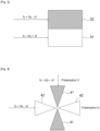
- FIG. 3 presents a first solution using partitioning of the transmitting antenna.
- the latter is partitioned into two radiating parts.
- a first part 31 is reserved for the transmission of the first signal f 0 + ⁇ f e + ⁇ f .
- the second part 32 is reserved for the transmission of the second signal f 0 + ⁇ f e - ⁇ f .
- the partition is carried out in such a way that the radiation of the signal is carried out under satisfactory conditions, in particular with regard to the secondary lobes and the lobe openings.
- FIG. 4 illustrates another solution where two radiating parts 41, 42 radiating in orthogonal polarizations are interleaved.
- a first part 41 is reserved for the emission of the first signal f 0 + ⁇ f e + ⁇ f according to the vertical polarization V.
- the second part 42 is reserved for the emission of the second signal f 0 + ⁇ f e - ⁇ f according to the horizontal polarization H.
- the Doppler speed V can be obtained from the measurement of the received frequencies f rec2 , f rec1 to the nearest factor 2 ⁇ f , with very low drift due to the high stability of the source 22. More particularly, the measurement of the speed V is a function of the ratio ( f rec 2 - f rec 1 ) / 2 ⁇ f, the difference 2 ⁇ f between the two carriers on transmission being more precise, more stable, than the nominal transmission frequency f0 .
- T duration counting interval
- ⁇ n 2 ⁇ f vs + V vs ⁇ V T 0 ⁇ T O ⁇ F F ⁇ 2 ⁇ fT 0 1 + 2 V vs 1 ⁇ ⁇ F F ⁇ 2 ⁇ fT 0 1 + 2 V vs ⁇ ⁇ F F by neglecting the second order, we obtain the measurement of the Doppler speed by involving ⁇ f according to the following equation: ⁇ n 2 T 0 ⁇ f ⁇ 1 + 2 V vs ⁇ ⁇ F F
- FIG. 5 presents an example of a block diagram of a reception device according to the invention making it possible to obtain the Doppler speed V as a function of measuring the difference of these two received frequencies (carriers of the signal reflected by the target) and the difference frequency ⁇ f .
- a mixer 53 receives on a first input the reception signal picked up by the reception antenna 52 and receives on a second input a signal coming from a local oscillator 51 at the transposition frequency, close to the transmission frequency, equal f 0 - f FI , the output signal of the mixer being conventionally transposed to the intermediate frequency f FI characterizing heterodyne reception.
- the output signal from the mixer is presented at the input of two band-pass filters 54, 55.
- a first bandpass filter 54 selects the line at the frequency f FI - ⁇ f , transposition of the received carrier which had been transmitted at f 0 + ⁇ f e - ⁇ f .
- a second bandpass filter 55 selects the line at the frequency f FI + ⁇ f , transposition of the received carrier which had been transmitted f 0 + ⁇ f e + ⁇ f .
- Processing means exploit the two lines selected by the bandpass filters to calculate the difference in the received carriers f rec 2 - f rec 1 .
- a high precision clock 57 is used, producing a signal at a frequency F, for the transposition of the two lines into base frequency ( f 0 ). as well as for their sampling in this base frequency.
- the processing means 56 calculate the Doppler speed according to equation (2). We thus obtain the Doppler speed of the targets detected by the reception antenna 51.
- the source 57 must have a sufficient level of stability to sample the signals coming from the filters 54, 55 with precision and consequently to calculate the difference in the frequencies received with precision. Its frequency F is low, in any case lower than the base frequency.
- the transposition of the received signal does not use a high stability source.
- the source used 51 can have a variable frequency, without particular stability, to manage frequency agility.
- Baseband sampling necessary in processing 56 to find the frequency difference (hence the Doppler speed) therefore uses a clock 57 of fixed frequency, rather low, but of high precision. There is not necessarily an interaction between the two sources 51, 57.
- the invention makes it possible to overcome the drift of the local oscillators of each radar, thus eliminating the drift of the local oscillator 21 generating the microwave waves on transmission and the drift of the local oscillator 51 generating microwave waves at reception.
Landscapes
- Engineering & Computer Science (AREA)
- Radar, Positioning & Navigation (AREA)
- Remote Sensing (AREA)
- Computer Networks & Wireless Communication (AREA)
- Physics & Mathematics (AREA)
- General Physics & Mathematics (AREA)
- Radar Systems Or Details Thereof (AREA)
Claims (7)
- Verfahren zur Messung der Dopplergeschwindigkeit eines Ziels, das von einer multistatischen Radarvorrichtung erfasst wird, die mindestens ein erstes Radar (E), das ein Sendesignal in Richtung des Ziels (C) erzeugt, und ein zweites Radar (R), welches das von dem Ziel rückgestreute Signal empfängt, umfasst, wobei das zweite Radar Kenntnis hat:- von Koordinaten des ersten Radars,- von einem Geschwindigkeitsvektor des ersten Radars,- von einer Richtung, die vom ersten Radar beleuchtet wird,- von einer zentralen Sendefrequenz (f0), die vom ersten Radar verwendet wird,- von einer Wellenform, die vom ersten Radar verwendete wird,wobei beim Senden zwei Trägerwellen mit einem gegebenen Frequenzabstand (2Δf) erzeugt werden (23, 24, 25), wobei der Frequenzabstand dem zweiten Radar bekannt ist, wobei das Verfahren zur Messung der Dopplergeschwindigkeit eines Ziels dadurch gekennzeichnet ist, dass die Messung der Dopplergeschwindigkeit im Empfang eine Funktion der Differenz der Empfangsfrequenzen der Trägerwellen ist, geteilt durch den Frequenzabstand (2Δf).
- Verfahren nach Anspruch 1, wobei die beiden Trägerwellen beim Senden durch Mischen (23) einer Welle mit einer Frequenz nahe der Sendefrequenz (21) und einer Welle mit niedrigerer Frequenz (22) erzeugt werden, die fest und frequenzstabiler als die Sendefrequenz ist.
- Verfahren nach einem der vorhergehenden Ansprüche, wobei die Sendeantenne des ersten Radars in mindestens zwei Teile (31, 32) abgegrenzt ist, wobei ein erster Teil (31) für die Aussendung einer Trägerwelle und ein zweiter Teil (32) für die Aussendung der anderen Trägerwelle bestimmt ist.
- Verfahren nach einem der Ansprüche 1 oder 2, wobei eine Trägerwelle gemäß einer Polarisation (41) gesendet wird, wobei die andere Trägerwelle gemäß einer anderen Polarisation (42) gesendet wird.
- Verfahren nach einem der vorhergehenden Ansprüche, wobei beim Empfang die Frequenzumsetzung der Empfangssignale der von dem Ziel (C) reflektierten Trägerwellen durchgeführt wird, indem sie mit einer Welle mit einer der Sendefrequenz benachbarten Frequenz, die von einem ersten Taktgeber (51) geliefert wird, gemischt werden (53).
- Verfahren nach Anspruch 5, wobei die Differenz der Empfangsfrequenzen der von dem Ziel (C) reflektierten Trägerwellen beim Empfang unter Verwendung eines zweiten Taktgebers (57) gemessen wird, der genauer ist als der erste Taktgeber (51).
- Verfahren nach Anspruch 6, wobei die beiden Taktgeber unabhängig sind.
Applications Claiming Priority (2)
| Application Number | Priority Date | Filing Date | Title |
|---|---|---|---|
| FR1914853A FR3105437B1 (fr) | 2019-12-19 | 2019-12-19 | Procede de mesure doppler pour dispositif radar multistatique, dispositif radar mettant en oeuvre un tel procede |
| PCT/EP2020/083921 WO2021121928A1 (fr) | 2019-12-19 | 2020-11-30 | Procede de mesure doppler pour dispositif radar multistatique, dispositif radar mettant en œuvre un tel procede |
Publications (2)
| Publication Number | Publication Date |
|---|---|
| EP4078227A1 EP4078227A1 (de) | 2022-10-26 |
| EP4078227B1 true EP4078227B1 (de) | 2024-02-21 |
Family
ID=71094414
Family Applications (1)
| Application Number | Title | Priority Date | Filing Date |
|---|---|---|---|
| EP20812061.8A Active EP4078227B1 (de) | 2019-12-19 | 2020-11-30 | Doppler-messverfahren für multistatische radarvorrichtung, radarvorrichtung zur durchführung eines solchen verfahrens |
Country Status (3)
| Country | Link |
|---|---|
| EP (1) | EP4078227B1 (de) |
| FR (1) | FR3105437B1 (de) |
| WO (1) | WO2021121928A1 (de) |
Family Cites Families (4)
| Publication number | Priority date | Publication date | Assignee | Title |
|---|---|---|---|---|
| NO921193D0 (no) * | 1992-03-26 | 1992-03-26 | Susar As | System for paavisning, maaling og klassifisering av luftfenomener |
| DE102004060087A1 (de) * | 2004-12-14 | 2006-06-22 | Robert Bosch Gmbh | Einrichtung für insbesondere bistatische Radaranwendungen |
| FR2968406B1 (fr) * | 2010-12-03 | 2013-04-12 | Thales Sa | Systeme de mesure de la vitesse radiale d'un mobile |
| US10203405B2 (en) * | 2013-04-25 | 2019-02-12 | The United States Of America As Represented By The Secretary Of The Army | Multitone radar with range determination and method of use |
-
2019
- 2019-12-19 FR FR1914853A patent/FR3105437B1/fr active Active
-
2020
- 2020-11-30 EP EP20812061.8A patent/EP4078227B1/de active Active
- 2020-11-30 WO PCT/EP2020/083921 patent/WO2021121928A1/fr unknown
Also Published As
| Publication number | Publication date |
|---|---|
| FR3105437B1 (fr) | 2021-12-10 |
| FR3105437A1 (fr) | 2021-06-25 |
| WO2021121928A1 (fr) | 2021-06-24 |
| EP4078227A1 (de) | 2022-10-26 |
Similar Documents
| Publication | Publication Date | Title |
|---|---|---|
| US11366228B2 (en) | Method and system for time separated quadrature detection of doppler effects in optical range measurements | |
| US11567351B2 (en) | Methods for computation-free wideband spectral correlation and analysis | |
| JP6558918B2 (ja) | マルチスタティックfmcwレーダーを用いるマイナス擬似レンジ処理 | |
| EP0258917B1 (de) | Frequenzmoduliertes Dauerstrichradar zur Entfernungsmessung | |
| EP0575221B1 (de) | Verfahren für Radargerät zum Eliminieren der Signale von Hindernissen und Anwendungen dafür | |
| EP0118342B1 (de) | Mit kontinuierlichen, frequenzmodulierten Wellen arbeitendes Radar und seine Anwendung für einen Höhenmesser | |
| EP3436845A1 (de) | Lidar-system und -verfahren mit direktdetektion mit frequenzmodulation (fm)-sender und quadraturempfänger | |
| FR3058227A1 (fr) | Radar fmcw multifaisceaux, notamment pour automobile | |
| FR2722005A1 (fr) | Appareil et procede pour attenuer les ambiguites dans les radars doppler a impulsions | |
| US20040150548A1 (en) | Linear frequency modulation superimposed on double sideband diplex radar | |
| US20040046689A1 (en) | Signal processing | |
| EP1096269A2 (de) | Zweiseitenband-DIPLEX-HETERODYN-RADARGERÄT | |
| US11555881B2 (en) | Locating method for localizing at least one object using wave-based signals and locating system | |
| EP0143497B1 (de) | Mit stetigen frequenzmodulierten Wellen arbeitendes Monopulsradargerät mit Achsenstabilisierung | |
| Scotti et al. | Multi-frequency lidar/radar integrated system for robust and flexible doppler measurements | |
| JP2019090791A (ja) | 単一の移動プラットフォームから測定された到達周波数(foa)を使用する、エミッタの場所決定 | |
| EP3171195A2 (de) | Verfahren zur lokalisierung einer bake | |
| EP4078227B1 (de) | Doppler-messverfahren für multistatische radarvorrichtung, radarvorrichtung zur durchführung eines solchen verfahrens | |
| JPH0743453A (ja) | 短波レーダ装置 | |
| Sandström et al. | A study of some FMCW radar algorithms for target location at low frequencies | |
| EP2410350A1 (de) | Antennenvorrichtung mit synthetischer Öffnung zur Aussendung von Signalen eines Satellitennavigationssystems, das eine Trägerwelle und Mittel zur Bestimmung ihrer Verlaufsbahn umfasst | |
| FR3058530A1 (fr) | Procede de controle de la compatibilite electromagnetique d'un detecteur de radars avec au moins un emetteur de bord de signaux impulsionnels | |
| EP2341363A1 (de) | Antwortsystem auf ein von einem Radar ausgesendetes Signal, und Einsatz dieses Systems insbesondere für Tests von Radaren, hauptsächlich vom Typ MTI | |
| EP3538917B1 (de) | Verfahren zum testen der elektromagnetischen verträglichkeit eines radardetektors mit mindestens einem impulssignalgeber an bord | |
| Laghezza et al. | Integrated multi-frequency lidar/radar system for precise and robust Doppler measurements |
Legal Events
| Date | Code | Title | Description |
|---|---|---|---|
| STAA | Information on the status of an ep patent application or granted ep patent |
Free format text: STATUS: UNKNOWN |
|
| STAA | Information on the status of an ep patent application or granted ep patent |
Free format text: STATUS: THE INTERNATIONAL PUBLICATION HAS BEEN MADE |
|
| PUAI | Public reference made under article 153(3) epc to a published international application that has entered the european phase |
Free format text: ORIGINAL CODE: 0009012 |
|
| STAA | Information on the status of an ep patent application or granted ep patent |
Free format text: STATUS: REQUEST FOR EXAMINATION WAS MADE |
|
| 17P | Request for examination filed |
Effective date: 20220523 |
|
| AK | Designated contracting states |
Kind code of ref document: A1 Designated state(s): AL AT BE BG CH CY CZ DE DK EE ES FI FR GB GR HR HU IE IS IT LI LT LU LV MC MK MT NL NO PL PT RO RS SE SI SK SM TR |
|
| DAV | Request for validation of the european patent (deleted) | ||
| DAX | Request for extension of the european patent (deleted) | ||
| P01 | Opt-out of the competence of the unified patent court (upc) registered |
Effective date: 20230427 |
|
| GRAP | Despatch of communication of intention to grant a patent |
Free format text: ORIGINAL CODE: EPIDOSNIGR1 |
|
| STAA | Information on the status of an ep patent application or granted ep patent |
Free format text: STATUS: GRANT OF PATENT IS INTENDED |
|
| INTG | Intention to grant announced |
Effective date: 20231129 |
|
| GRAS | Grant fee paid |
Free format text: ORIGINAL CODE: EPIDOSNIGR3 |
|
| GRAA | (expected) grant |
Free format text: ORIGINAL CODE: 0009210 |
|
| STAA | Information on the status of an ep patent application or granted ep patent |
Free format text: STATUS: THE PATENT HAS BEEN GRANTED |
|
| AK | Designated contracting states |
Kind code of ref document: B1 Designated state(s): AL AT BE BG CH CY CZ DE DK EE ES FI FR GB GR HR HU IE IS IT LI LT LU LV MC MK MT NL NO PL PT RO RS SE SI SK SM TR |
|
| RAP3 | Party data changed (applicant data changed or rights of an application transferred) |
Owner name: THALES |
|
| REG | Reference to a national code |
Ref country code: GB Ref legal event code: FG4D Free format text: NOT ENGLISH |
|
| REG | Reference to a national code |
Ref country code: CH Ref legal event code: EP |
|
| REG | Reference to a national code |
Ref country code: DE Ref legal event code: R096 Ref document number: 602020026158 Country of ref document: DE |
|
| REG | Reference to a national code |
Ref country code: IE Ref legal event code: FG4D Free format text: LANGUAGE OF EP DOCUMENT: FRENCH |