EP4077920B1 - Windturbinensteuerung - Google Patents
Windturbinensteuerung Download PDFInfo
- Publication number
- EP4077920B1 EP4077920B1 EP20902394.4A EP20902394A EP4077920B1 EP 4077920 B1 EP4077920 B1 EP 4077920B1 EP 20902394 A EP20902394 A EP 20902394A EP 4077920 B1 EP4077920 B1 EP 4077920B1
- Authority
- EP
- European Patent Office
- Prior art keywords
- motion
- controller
- wind turbine
- frequency range
- damping
- Prior art date
- Legal status (The legal status is an assumption and is not a legal conclusion. Google has not performed a legal analysis and makes no representation as to the accuracy of the status listed.)
- Active
Links
Images


Classifications
-
- F—MECHANICAL ENGINEERING; LIGHTING; HEATING; WEAPONS; BLASTING
- F03—MACHINES OR ENGINES FOR LIQUIDS; WIND, SPRING, OR WEIGHT MOTORS; PRODUCING MECHANICAL POWER OR A REACTIVE PROPULSIVE THRUST, NOT OTHERWISE PROVIDED FOR
- F03D—WIND MOTORS
- F03D7/00—Controlling wind motors
- F03D7/02—Controlling wind motors the wind motors having rotation axis substantially parallel to the air flow entering the rotor
- F03D7/0296—Controlling wind motors the wind motors having rotation axis substantially parallel to the air flow entering the rotor to prevent, counteract or reduce noise emissions
-
- F—MECHANICAL ENGINEERING; LIGHTING; HEATING; WEAPONS; BLASTING
- F03—MACHINES OR ENGINES FOR LIQUIDS; WIND, SPRING, OR WEIGHT MOTORS; PRODUCING MECHANICAL POWER OR A REACTIVE PROPULSIVE THRUST, NOT OTHERWISE PROVIDED FOR
- F03D—WIND MOTORS
- F03D7/00—Controlling wind motors
- F03D7/02—Controlling wind motors the wind motors having rotation axis substantially parallel to the air flow entering the rotor
-
- B—PERFORMING OPERATIONS; TRANSPORTING
- B63—SHIPS OR OTHER WATERBORNE VESSELS; RELATED EQUIPMENT
- B63B—SHIPS OR OTHER WATERBORNE VESSELS; EQUIPMENT FOR SHIPPING
- B63B35/00—Vessels or similar floating structures specially adapted for specific purposes and not otherwise provided for
- B63B35/44—Floating buildings, stores, drilling platforms, or workshops, e.g. carrying water-oil separating devices
-
- B—PERFORMING OPERATIONS; TRANSPORTING
- B63—SHIPS OR OTHER WATERBORNE VESSELS; RELATED EQUIPMENT
- B63B—SHIPS OR OTHER WATERBORNE VESSELS; EQUIPMENT FOR SHIPPING
- B63B39/00—Equipment to decrease pitch, roll, or like unwanted vessel movements; Apparatus for indicating vessel attitude
-
- F—MECHANICAL ENGINEERING; LIGHTING; HEATING; WEAPONS; BLASTING
- F03—MACHINES OR ENGINES FOR LIQUIDS; WIND, SPRING, OR WEIGHT MOTORS; PRODUCING MECHANICAL POWER OR A REACTIVE PROPULSIVE THRUST, NOT OTHERWISE PROVIDED FOR
- F03D—WIND MOTORS
- F03D13/00—Assembly, mounting or commissioning of wind motors; Arrangements specially adapted for transporting wind motor components
- F03D13/20—Arrangements for mounting or supporting wind motors; Masts or towers for wind motors
- F03D13/25—Arrangements for mounting or supporting wind motors; Masts or towers for wind motors specially adapted for offshore installation
-
- F—MECHANICAL ENGINEERING; LIGHTING; HEATING; WEAPONS; BLASTING
- F03—MACHINES OR ENGINES FOR LIQUIDS; WIND, SPRING, OR WEIGHT MOTORS; PRODUCING MECHANICAL POWER OR A REACTIVE PROPULSIVE THRUST, NOT OTHERWISE PROVIDED FOR
- F03D—WIND MOTORS
- F03D7/00—Controlling wind motors
- F03D7/02—Controlling wind motors the wind motors having rotation axis substantially parallel to the air flow entering the rotor
- F03D7/0202—Controlling wind motors the wind motors having rotation axis substantially parallel to the air flow entering the rotor controlling floating wind motors
-
- F—MECHANICAL ENGINEERING; LIGHTING; HEATING; WEAPONS; BLASTING
- F03—MACHINES OR ENGINES FOR LIQUIDS; WIND, SPRING, OR WEIGHT MOTORS; PRODUCING MECHANICAL POWER OR A REACTIVE PROPULSIVE THRUST, NOT OTHERWISE PROVIDED FOR
- F03D—WIND MOTORS
- F03D7/00—Controlling wind motors
- F03D7/02—Controlling wind motors the wind motors having rotation axis substantially parallel to the air flow entering the rotor
- F03D7/022—Adjusting aerodynamic properties of the blades
- F03D7/0224—Adjusting blade pitch
-
- F—MECHANICAL ENGINEERING; LIGHTING; HEATING; WEAPONS; BLASTING
- F03—MACHINES OR ENGINES FOR LIQUIDS; WIND, SPRING, OR WEIGHT MOTORS; PRODUCING MECHANICAL POWER OR A REACTIVE PROPULSIVE THRUST, NOT OTHERWISE PROVIDED FOR
- F03D—WIND MOTORS
- F03D7/00—Controlling wind motors
- F03D7/02—Controlling wind motors the wind motors having rotation axis substantially parallel to the air flow entering the rotor
- F03D7/0276—Controlling wind motors the wind motors having rotation axis substantially parallel to the air flow entering the rotor controlling rotor speed, e.g. variable speed
-
- F—MECHANICAL ENGINEERING; LIGHTING; HEATING; WEAPONS; BLASTING
- F03—MACHINES OR ENGINES FOR LIQUIDS; WIND, SPRING, OR WEIGHT MOTORS; PRODUCING MECHANICAL POWER OR A REACTIVE PROPULSIVE THRUST, NOT OTHERWISE PROVIDED FOR
- F03D—WIND MOTORS
- F03D7/00—Controlling wind motors
- F03D7/02—Controlling wind motors the wind motors having rotation axis substantially parallel to the air flow entering the rotor
- F03D7/028—Controlling wind motors the wind motors having rotation axis substantially parallel to the air flow entering the rotor controlling wind motor output power
-
- F—MECHANICAL ENGINEERING; LIGHTING; HEATING; WEAPONS; BLASTING
- F03—MACHINES OR ENGINES FOR LIQUIDS; WIND, SPRING, OR WEIGHT MOTORS; PRODUCING MECHANICAL POWER OR A REACTIVE PROPULSIVE THRUST, NOT OTHERWISE PROVIDED FOR
- F03D—WIND MOTORS
- F03D7/00—Controlling wind motors
- F03D7/02—Controlling wind motors the wind motors having rotation axis substantially parallel to the air flow entering the rotor
- F03D7/0298—Controlling wind motors the wind motors having rotation axis substantially parallel to the air flow entering the rotor to prevent, counteract or reduce vibrations
- F03D7/0302—Controlling wind motors the wind motors having rotation axis substantially parallel to the air flow entering the rotor to prevent, counteract or reduce vibrations of the tower
-
- F—MECHANICAL ENGINEERING; LIGHTING; HEATING; WEAPONS; BLASTING
- F03—MACHINES OR ENGINES FOR LIQUIDS; WIND, SPRING, OR WEIGHT MOTORS; PRODUCING MECHANICAL POWER OR A REACTIVE PROPULSIVE THRUST, NOT OTHERWISE PROVIDED FOR
- F03D—WIND MOTORS
- F03D7/00—Controlling wind motors
- F03D7/02—Controlling wind motors the wind motors having rotation axis substantially parallel to the air flow entering the rotor
- F03D7/04—Automatic control; Regulation
- F03D7/042—Automatic control; Regulation by means of an electrical or electronic controller
- F03D7/043—Automatic control; Regulation by means of an electrical or electronic controller characterised by the type of control logic
-
- B—PERFORMING OPERATIONS; TRANSPORTING
- B63—SHIPS OR OTHER WATERBORNE VESSELS; RELATED EQUIPMENT
- B63B—SHIPS OR OTHER WATERBORNE VESSELS; EQUIPMENT FOR SHIPPING
- B63B35/00—Vessels or similar floating structures specially adapted for specific purposes and not otherwise provided for
- B63B35/44—Floating buildings, stores, drilling platforms, or workshops, e.g. carrying water-oil separating devices
- B63B2035/4433—Floating structures carrying electric power plants
- B63B2035/446—Floating structures carrying electric power plants for converting wind energy into electric energy
-
- F—MECHANICAL ENGINEERING; LIGHTING; HEATING; WEAPONS; BLASTING
- F05—INDEXING SCHEMES RELATING TO ENGINES OR PUMPS IN VARIOUS SUBCLASSES OF CLASSES F01-F04
- F05B—INDEXING SCHEME RELATING TO WIND, SPRING, WEIGHT, INERTIA OR LIKE MOTORS, TO MACHINES OR ENGINES FOR LIQUIDS COVERED BY SUBCLASSES F03B, F03D AND F03G
- F05B2240/00—Components
- F05B2240/90—Mounting on supporting structures or systems
- F05B2240/93—Mounting on supporting structures or systems on a structure floating on a liquid surface
-
- F—MECHANICAL ENGINEERING; LIGHTING; HEATING; WEAPONS; BLASTING
- F05—INDEXING SCHEMES RELATING TO ENGINES OR PUMPS IN VARIOUS SUBCLASSES OF CLASSES F01-F04
- F05B—INDEXING SCHEME RELATING TO WIND, SPRING, WEIGHT, INERTIA OR LIKE MOTORS, TO MACHINES OR ENGINES FOR LIQUIDS COVERED BY SUBCLASSES F03B, F03D AND F03G
- F05B2270/00—Control
- F05B2270/30—Control parameters, e.g. input parameters
- F05B2270/334—Vibration measurements
-
- F—MECHANICAL ENGINEERING; LIGHTING; HEATING; WEAPONS; BLASTING
- F05—INDEXING SCHEMES RELATING TO ENGINES OR PUMPS IN VARIOUS SUBCLASSES OF CLASSES F01-F04
- F05B—INDEXING SCHEME RELATING TO WIND, SPRING, WEIGHT, INERTIA OR LIKE MOTORS, TO MACHINES OR ENGINES FOR LIQUIDS COVERED BY SUBCLASSES F03B, F03D AND F03G
- F05B2270/00—Control
- F05B2270/30—Control parameters, e.g. input parameters
- F05B2270/342—Wave conditions, e.g. amplitude, frequency or direction
-
- Y—GENERAL TAGGING OF NEW TECHNOLOGICAL DEVELOPMENTS; GENERAL TAGGING OF CROSS-SECTIONAL TECHNOLOGIES SPANNING OVER SEVERAL SECTIONS OF THE IPC; TECHNICAL SUBJECTS COVERED BY FORMER USPC CROSS-REFERENCE ART COLLECTIONS [XRACs] AND DIGESTS
- Y02—TECHNOLOGIES OR APPLICATIONS FOR MITIGATION OR ADAPTATION AGAINST CLIMATE CHANGE
- Y02E—REDUCTION OF GREENHOUSE GAS [GHG] EMISSIONS, RELATED TO ENERGY GENERATION, TRANSMISSION OR DISTRIBUTION
- Y02E10/00—Energy generation through renewable energy sources
- Y02E10/70—Wind energy
- Y02E10/72—Wind turbines with rotation axis in wind direction
-
- Y—GENERAL TAGGING OF NEW TECHNOLOGICAL DEVELOPMENTS; GENERAL TAGGING OF CROSS-SECTIONAL TECHNOLOGIES SPANNING OVER SEVERAL SECTIONS OF THE IPC; TECHNICAL SUBJECTS COVERED BY FORMER USPC CROSS-REFERENCE ART COLLECTIONS [XRACs] AND DIGESTS
- Y02—TECHNOLOGIES OR APPLICATIONS FOR MITIGATION OR ADAPTATION AGAINST CLIMATE CHANGE
- Y02E—REDUCTION OF GREENHOUSE GAS [GHG] EMISSIONS, RELATED TO ENERGY GENERATION, TRANSMISSION OR DISTRIBUTION
- Y02E10/00—Energy generation through renewable energy sources
- Y02E10/70—Wind energy
- Y02E10/727—Offshore wind turbines
Definitions
- the pitch of the rotor blades is controlled in order to regulate the power output.
- the power output generated by the turbine is maximised at a particular wind speed, known as the rated wind speed.
- the blade pitch is kept approximately constant at an angle that provides maximum power output.
- the blade pitch is adjusted in order to produce a constant power output and prevent excessively high power outputs that could damage the generator and/or its associated electronics.
- This constant power output may be referred to as the rated power of the wind turbine.
- the rotor may be controlled so that it rotates at a constant speed. This may be referred to as a desired and/or target rotor speed.
- the wind turbine may also have a cut-out wind speed, which is a wind speed at which the turbine shuts down to avoid damage.
- the blade pitch angle is adjusted to reduce the torque acting on the rotor to reduce the thrust and thereby maintain a constant power output.
- the damping force acting on the wind turbine's motions is also reduced and can become negative.
- the motions can be exacerbated and their amplitude increases. This then may result in a further change in the relative wind speed and a further adjustment to the blade pitch, making the motions even larger.
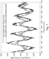
- Figure 1 shows the thrust force as a function of wind speed for a 2.3 MW turbine using the standard blade pitch control described above.
- the thrust force for wind speeds above 12 ms -1 (which may be the rated wind speed) decreases with increasing wind speed due to adjustment of the blade pitch, and consequently negative damping may be introduced into the system in this wind speed range.
- the first peak occurs at frequencies of around 0.008 Hz and corresponds to the rigid body oscillations of the support structure that may be caused by the surge motion of the floating wind turbine coupled with the restoring effects of the mooring lines. In these oscillations the tower moves forwards and backwards horizontally but remains in an essentially vertical position. These surge motions may be caused by changes in wind speed which excite the natural surge frequency of a wind turbine and may be more likely to occur in calmer waters.
- PI controller proportional integral controller
- the PI controller is a feedback controller which controls the blade pitch and thereby the rotor speed (i.e. the rotational frequency of the rotor) on the basis of a weighted sum of the error (the difference between the output/actual rotor speed and the desired/target rotor speed) and the integral of that value.
- the generator torque is typically controlled to produce either a constant torque or a constant power.
- WO 2010/076557 describes a turbine controller which is designed to counteract the problem of negative damping, which occurs above rated wind speed, and to reduce resonant low frequency motion in the axial direction, specifically in relation to pitch motions in a floating wind turbine. This is achieved by collectively adjusting the pitch of the blades to create a damping and/or restoring force in the axial direction.
- WO 2014/096419 describes a controller for controlling the yawing motion of the turbines that may be caused by uneven air flow over the rotor-disk. This is achieved by dynamic pitching of turbine blades, meaning that the pitch of individual turbine blades may be adjusted to bring yawing motion to within a desired range.
- controllers are typically aimed at avoiding negative damping for certain motions made by floating wind turbines and may provide some amount of positive damping to the pitch motion of floating wind turbines.
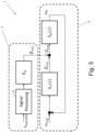
- FIG. 3 An example of a control system 1 with a vibration controller with active damping for a fixed-base wind turbine is shown in Figure 3 .
- the upper line in Figure 3 is the active vibration controller part 2 of the control system, which uses measurements of the tower velocity v nacelle to prevent or minimise negative damping, as described above.
- the rest of the system is the standard controller 4 which provides blade pitch control based on the rotor speed.
- a transfer function gives the ratio between Laplace transforms of the output and the input to a system component as a function of a variable s (where s is usually related to a spatial or temporal frequency, such as angular frequency). That is to say, transfer functions enable analysis of components such that they may be represented in block diagrams or other simplified diagrams. The background mathematics for this kind of function is known and is discussed for example in WO 2010/076557 .
- the transfer function h c ( s ) may be provided by means of a PI controller.
- the values of the parameters of the controller may be determined by conventional tuning of the control system to the desired bandwidth.
- the signal processing block 6 in Figure 3 will typically consist of some suitable filtering for removal of certain frequency components.
- the control parameters of the blade pitch controller are tuned such that the bandwidth of the standard part of the controller lies below the natural frequency of the first bending mode of the tower, in order to prevent or minimise negative damping of the structural bending oscillations.
- a vibration control part such as the one shown in Figure 3 may be provided to provide active positive damping for vibrations with frequencies of the first bending mode since these vibrations may have a frequency that is not suppressed by this part of the controller.
- floating wind turbines may also have structural bending vibrations with natural frequencies around 0.3 to 1 Hz. However, they also have rigid body oscillations with frequencies for example around 0.03 to 0.04 Hz and/or around 0.008 Hz.
- the controller of Figure 3 cannot simply be tuned to act on the lower frequency oscillations experienced by floating wind turbines.
- the blade pitch controllers for floating wind turbines may be a modification of the standard blade pitch controller of Figure 3 and may comprise active damping means arranged to further control the blade pitch on the basis of a speed of a point on the wind turbine structure.
- the active damping means may be arranged to convert the speed of a point on the wind turbine structure into a rotor speed error and the same transfer function that is used in the standard blade pitch control means is used in the active damping means in order to convert the rotor speed error into a correction to the blade pitch. This is disclosed in WO 2010/076557 .
- US 2015/003984 A1 discloses a blade pitch controller for adjusting pitch of individual blades in response to bending moments in wind turbines, including offshore wind turbines.
- JP 2014 111924 A discloses a floating wind turbine comprising a blade pitch controller with an active damping control for damping rocking motions of the turbine.
- the present invention provides a controller (i.e. a blade pitch controller and/or a generator torque controller) for a floating wind turbine comprising a rotor with a plurality of rotor blades connected to a generator, wherein the controller comprises: an active damping controller for calculating one or more outputs for damping both a first motion of the floating wind turbine in a first frequency range and a second motion of the floating wind turbine in a second frequency range based on an input of the first motion and an input of the second motion; wherein the active damping controller comprises a first control loop and a second control loop, wherein the first control loop receives the input of the first motion and the second control loop receives the input of the second motion, wherein the active damping controller comprises a low pass filter, wherein a first low pass filter frequency for the first control loop and a second low pass filter frequency for the second control loop is set according to the first frequency range and the second frequency range respectively, and wherein the controller is arranged to calculate an output for controlling
- the invention provides a floating wind turbine comprising a rotor with a plurality of rotor blades connected to a generator and a controller, wherein the controller comprises: an active damping controller for calculating one or more outputs for damping both a first motion of the floating wind turbine in a first frequency range and a second motion of the floating wind turbine in a second frequency range based on an input of the first motion and an input of the second motion; wherein the controller is arranged to calculate an output for controlling a blade pitch of one or more of the plurality of rotor blades and/or for controlling a torque of the generator based on an actual rotor speed, a target rotor speed, and the one or more outputs from the active damping controller such that both the first motion and the second motion will be damped.
- the floating wind turbine of the second aspect comprises a controller in accordance with the first aspect.
- the invention provides a method of controlling the blade pitch and/or the generator torque of a floating wind turbine, wherein the floating wind turbine comprises a rotor with a plurality of rotor blades connected to a generator, the method comprising: receiving, in a first control loop, an input of a first motion of the floating wind turbine in a first frequency range, wherein a first low pass filter frequency for the first control loop is set according to the first frequency range; receiving, in a second control loop, an input of a second motion of the floating wind turbine in a second frequency range, wherein a second low pass filter frequency for the second control loop is set according to the second frequency range; calculating one or more damping outputs for damping both the first motion and the second motion based on the input of the first motion and the input of the second motion; and calculating an output for controlling the blade pitch of one or more of the plurality of rotor blades and/or for controlling the torque of the generator based on an actual rotor speed, a target rotor
- the method of the third aspect may be performed using the controller of the first aspect and/or the floating wind turbine of the second aspect.
- the controller of the first aspect and/or the floating wind turbine of the second aspect may be configured to perform the method of the third aspect.
- the invention provides a computer program product comprising instructions that, when executed on processing circuitry for a floating wind turbine, will configure the processing circuitry to control a blade pitch for one or more rotors of the floating wind turbine and/or to control the generator torque of the floating wind turbine, the instructions comprising: receiving an input of a first motion of the floating wind turbine in a first frequency range; receiving an input of a second motion of the floating wind turbine in a second frequency range; calculating one or more damping outputs for damping both the first motion and the second motion based on the input of the first motion and the input of the second motion; and calculating an output for controlling a blade pitch of one or more of the plurality of rotor blades based on an actual rotor speed, a target rotor speed, and the one or more damping outputs such that both the first motion and the second motion will be damped.
- the computer program product of the fourth aspect may be provided in the controller of the first aspect and/or the floating wind turbine of the second aspect.
- the computer program product of the fourth aspect may be used to perform the method of the third aspect.
- the computer program product may comprise instructions that, when executed on processing circuitry for a floating wind turbine, will configure the processing circuitry to perform the method of the third aspect.
- the present invention allows for the effective damping of motions of different frequencies. This is achieved by receiving both an input of a first motion in a first frequency range and an input of a second motion in a second frequency range such that one or more outputs for damping both the higher and lower frequency motions can be calculated.
- the motions are rigid body motions.
- Existing active damping controllers for wind turbines are typically directed to the damping of floating wind turbine motions having a period of below about 50 seconds (about 0.02 Hz).
- the natural period of pitch motions typically occur in the range of about 25 to 50 seconds, which is significantly faster or slower than the period of other motions experienced by a floating wind turbine, such as surge motions.
- the period of surge motions for example may be about 60 seconds, or be even longer at around 2 or 3 minutes.
- the present invention may allow effective damping of motion at multiple frequencies, such as the pitch motion (which is the motion damped by typical blade pitch controllers) and the lower frequency surge motion of floating wind turbines.
- the controller may for example be able to effectively damp motions, such as pitch motion and surge motion, of floating wind turbines which occur in different frequency ranges.
- the controller is for controlling (i.e. damping) motions of the floating wind turbine.
- the controller may be referred to as a motion controller and/or a floating wind turbine motion controller.
- the controller is for calculating an output for controlling a blade pitch of one or more of the plurality of rotor blades and/or for controlling the torque of the generator, thus the controller may be referred to as a blade pitch controller and/or a generator torque controller.
- the first motion is a rigid body motion and the second motion is a rigid body motion.
- the motions may be axial motions, e.g. pitch and surge motions.
- the first motion may be pitch and/or surge motions in the first frequency range and the second motion may be pitch and/or surge motions in the second (e.g. lower) frequency range.
- the controller may be useful for floating wind turbines in locations with a mild wave climate. This is because in these locations wind induced loads may dominate overall mooring loads and the mooring loads may be caused by motions at a frequency different to other significant motions that are desired to be damped.
- the present invention may for example allow the reduction of excessive loads on a mooring system of the floating wind turbine, thereby extending the lifetime of the mooring system in addition to reducing loads on the wind turbine structure itself.
- the first motion and/or the second motion may be axial motions, i.e. pitch and/or surge.
- the first motion may be, or comprise, pitch motion and/or surge motion.
- the first frequency range may be about 0.02 to 0.05 Hz, or optionally within the range of about 0.03 to 0.04 Hz. This frequency range may pertain to any motions (or axial motions) of the floating wind turbine that have a natural or driven frequency within this range.
- the motions of the floating wind turbine that occur within these ranges may be dominated by pitch motions, but may also include other types of motions.
- the input of the first motion and/or the input of the second motion may be measured and/or estimated using the output from one or more sensors.
- the active damping controller/method may be for providing active damping control of the first motion (e.g. pitch motion of the floating wind turbine) and for providing active damping control of the second motion (e.g. surge motion of the floating wind turbine).
- first motion e.g. pitch motion of the floating wind turbine
- second motion e.g. surge motion of the floating wind turbine
- the active damping control of the second motion may be for reducing loads on the mooring system.
- the active damping controller comprises two control loops, i.e. a first control loop and a second control loop.
- the two control loops may be independent.
- the first control loop may be for providing active damping control of the first motion (e.g. pitch motion of the floating wind turbine).
- the second control loop may be for providing active damping control of the second motion (e.g. surge motion of the floating wind turbine).
- the first control loop and the second control loop includes different filtering and/or different parameter settings. This means that each control loop is tailored and/or optimised for the respective motions.
- the first control loop receives the input of the first motion, e.g. an input from a motion sensor provided on the floating wind turbine structure.
- the second control loop receives the input of the second motion, e.g. an input from or based on data from a differential global positioning system.
- the first control loop may be for calculating an output for damping the first motion and the second control loop may be for calculating an output for damping the second motion.
- the output for damping the first motion and/or second motion may be one or more of a rotor speed reference signal, a blade pitch adjustment and/or a generator torque adjustment.
- the active damping controller may be configured to calculate a rotor speed reference signal, a blade pitch adjustment and/or a generator torque adjustment based on a motion of the floating wind turbine in a first frequency range and/or based on a motion of the floating wind turbine in a second frequency range.
- the active damping controller may be configured to calculate a first rotor speed reference signal, a first blade pitch adjustment and/or a first generator torque adjustment based on a motion of the floating wind turbine in a first frequency range, a second rotor speed reference signal, a second blade pitch adjustment and/or a second generator torque adjustment based on a motion of the floating wind turbine in a second frequency range and/or a combined rotor speed reference signal, a combined blade pitch adjustment and/or a combined generator torque adjustment based on a motion of the floating wind turbine in a first frequency range and a motion in a second frequency range.
- the controller may be arranged to control a blade pitch of one or more of the plurality of rotor blades based on an actual rotor speed, a target rotor speed, and the output from the active damping controller which may comprise one or more of a first additional rotor speed reference signal, a first blade pitch adjustment, a second additional rotor speed reference signal, a second blade pitch adjustment, a combined additional rotor speed reference signal and/or a combined blade pitch adjustment.
- the controller may be arranged to control a torque of the generator based on an actual rotor speed, a target rotor speed, and the output from the active damping controller which may comprise one or more of a first additional rotor speed reference signal, a first generator torque adjustment, a second additional rotor speed reference signal, a second generator torque adjustment, a combined additional rotor speed reference signal and/or a combined generator torque adjustment.
- the controller may comprise a one or more converters.
- the converter may be, or comprise, a PI controller, a PID controller, a transfer function, a non-linear equation, some other function or some other conversion means for converting a rotor speed error into a blade pitch adjustment and/or a generator torque adjustment.
- the converter may be, or may be part of, a wind turbine control system.
- the controller may comprise a standard controller in addition to the active damping controller.
- the standard controller may be for calculating the output for controlling a blade pitch of one or more of the plurality of rotor blades and/or for controlling a torque of the generator.
- the standard controller may be for receiving the one or more outputs from the active damping controller.
- the standard controller may also receive the actual rotor speed and the target rotor speed.
- the output may be for controlling the pitch of the rotor blades collectively.
- the controller may be for providing collective blade pitch control.
- the actual rotor speed may be the speed that the rotor of the floating wind turbine is rotating.
- the target rotor speed may be the optimum rotor speed for power output.
- the target rotor speed may be referred to as the desired rotor speed and/or the optimum rotor speed.
- the target rotor speed may be the optimum attainable rotor speed for the given wind speed. Above rated wind speed, the target rotor speed may be the maximum speed for power output in the scenario that the wind turbine is not moving.
- the target rotor speed and first and second or combined rotor speed adjustment(s) to damp the first motion and the second motion may be combined to give a rotor speed reference.
- the actual rotor speed may be subtracted from the rotor speed reference to provide a rotor speed error.
- the rotor speed error (i.e. the difference between the actual rotor speed and the target rotor speed adjusted to damp the motions) may be converted to a blade pitch adjustment and/or a generator torque adjustment.
- the blade pitch adjustment and/or generator torque adjustment may cause the actual rotor speed to change. This may be to reduce the difference between the actual rotor speed and the reference rotor speed so as to reduce the rotor speed error.
- the blade pitch adjustment and/or generator torque adjustment may be used to control the wind turbine so as to tend the rotor speed error to zero.
- the blade pitch adjustment and/or generator torque adjustment may cause an optimum rotor speed whilst providing forces to damp the first and second motions and/or to prevent negative damping of the first and/or second motions.
- the active damping controller may comprise a first control loop (i.e. a control law) that calculates a first additional rotor speed reference signal ⁇ ref 1 (which may be the output for damping the first motion).
- the additional rotor speed reference signal may be calculated based on the measured or estimated velocity of the first motion ⁇ 1 a controller gain K 1 and a filter, e.g. h 1 ( s ).
- the filter may have a Laplace form.
- the active damping controller may comprise a second control loop (i.e. a control law) that calculates a second additional rotor speed reference signal ⁇ ref 2 (which may be the output for damping the second motion).
- the second additional rotor speed reference signal may be calculated based on the measured or estimated velocity of the second motion ⁇ 2 a controller gain K 2 and a filter, e.g. h 2 ( s ).
- ⁇ ref 2 h 2 s K 2 x ⁇ 2 h 2 ( s ) may be a second order low pass filter.
- the filter may have a Laplace form.
- the controller gain and/or the low pass filter frequency is different between the first and second control loops. This may allow the first control loop to be suitable for the first motion and the second control loop suitable for the second motion.
- the low pass filter frequency for the first control loop and the second control loop is set according to the first frequency range and the second frequency range respectively.
- ⁇ 1 and ⁇ 2 may be measured and/or estimated using the output from different sensors (as discussed above).
- ⁇ ref 1 and ⁇ ref 2 may be converted (either separately or together) in the active damping controller or in the standard controller to a blade pitch adjustment and/or a generator torque adjustment.
- the actual rotor speed ⁇ r may be taken from the total target rotor speed reference signal ⁇ ref to give a rotor speed error ⁇ error .
- the rotor speed error ⁇ error may be used to calculate a blade pitch adjustment and/or a generator torque. Because it includes ⁇ ref 1 and ⁇ ref 2 , the blade pitch adjustment and/or generator torque may result in the first motion and the second motion being damped.
- the controller may comprise a single converter (e.g. in the standard controller) for converting all of the rotor speed signals (e.g. once combined) to a blade pitch adjustment and/or a generator torque adjustment.
- the controller may comprise multiple converters for converting the rotor speed signals separately to blade pitch adjustments and/or a generator torque adjustments.
- the blade pitch adjustments and/or generator torque adjustments may be combined to provide a total blade pitch adjustment and/or a total generator torque adjustment that are used for controlling the floating wind turbine.
- the controller may be used to prevent negative damping of the first motion and/or the second motion.
- the controller/method may be used to control the floating wind turbine when the wind is above rated wind speed.
- the controller/method may provide additional active damping control of the second motion of the floating wind turbine in addition to providing active damping control of the first motion of the floating wind turbine (where the two motions are within different frequency ranges).
- the controller/method may be able to damp motions in a first frequency range that may give rise to loads on the floating wind turbine structure and damp motions of in a second frequency range that may give rise to loads on the mooring system of the floating wind turbine structure. This may be particularly effective at locations with mild wave climate where wind induced loads (which may be mitigated with the blade pitch and/or generator torque control) dominate the overall mooring loads.
- the floating wind turbine may be a spar buoy-type floating wind turbine.
- the floating wind turbine may be secured to the ocean floor through the use of a mooring system such as mooring lines and/or one or more articulated legs.
- the floating wind turbine may be a semi-submersible type floating wind turbine or any other kind of floating wind turbine.
- the floating wind turbine may comprise the first sensor and/or the second sensor.
- the invention may be an additional controller or additional software. This may be arranged to perform the method or at least part of the method.
- Software may be stored on a physical medium or on a cloud-based storage solution or on any other suitable medium.
- the controller may be retrofit to an existing floating wind turbine. This may be achieved by providing the existing floating wind turbine with the additional input(s), the additional sensor(s) and/or additional or updated code/software.
- the active damping controller may be code that is used to provide one or more outputs (such as rotor speed reference(s), blade pitch adjustment(s) and/or generator torque adjustment(s)) that can be used to damp the first motion and/or the second motion.
- outputs such as rotor speed reference(s), blade pitch adjustment(s) and/or generator torque adjustment(s)
- the controller/method Whilst the controller/method is described in relation to damping a first motion of a first frequency range and a second motion of a second frequency range, the controller/method may be able to damp further motions in further frequency ranges.
- the invention may be for damping a plurality of motions of a respective plurality of frequency ranges. This may be achieved by providing separate control loops for each frequency range. Each control loop may comprise filtering or other parameters for the particular frequency range it is designed to damp the motions of. A separate input (optionally each from separate sensors) may be provided for each motion in a different frequency range.
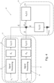
- Figure 4 illustrates a blade pitch controller 10 that can account for motions in different frequency ranges that may be experienced by a floating wind turbine.
- Figure 4 illustrates a blade pitch controller that comprises an active damping controller 12 for calculating blade pitch adjustments ⁇ 2 and ⁇ 3 for damping a first motion (e.g. pitch and/or surge) in a first frequency range and a second motion (e.g. surge) in a second frequency range respectively.
- the active damping controller 12 is coupled to a standard blade pitch controller 14.
- the blade pitch controller 10 is operable in the manner described at or above rated wind speed.
- the standard controller 14 subtracts an actual wind turbine rotor speed ⁇ r from a reference wind turbine rotor speed ⁇ ref 0 .
- the reference rotor speed ⁇ ref 0 is a target rotor speed at which the wind turbine may be at its most efficient operation when the floating wind turbine is not moving. Therefore, the standard pitch control means 14 attempts to continuously correct the pitch of turbine rotor blades to bring the actual rotor speed ⁇ r as close to the target rotor speed ⁇ ref 0 as possible.
- the standard pitch control means 14 does not account for any motions of the wind turbine structure itself, however.
- the active damping controller 12 in Figure 4 comprises a first damping control loop 16 for calculating an output for damping rigid body motions of the wind turbine in a first frequency range (which may for example be, or comprise, pitch motions) and a second active damping control loop 18 for calculating a second output for damping rigid body motions of the wind turbine in a second frequency range (which may for example be, or comprise, surge motions).
- a first measured or estimated velocity of the wind turbine v p (which may be referred to as ⁇ 1 ) is processed by the first signal processing means 20 and then operated on by the first active controller gain K p and the first active damper controller transfer function h p ( s ), which produces a first additional blade pitch adjustment signal ⁇ 2 .
- a second measured or estimated velocity of the wind turbine v s (which may be referred to as ⁇ 2 ) is processed by the second signal processing means 22 and then operated on by the second active controller gain K s and the second controller transfer function h s ( s ), which produces a second additional blade pitch adjustment signal ⁇ 3 .
- the first signal processing block 20 in the first damping control loop 16 for a floating turbine shown in Figure 4 uses a sharp low pass filter with a filter frequency that is sufficiently below the wave frequency range (0.05 to 0.2 Hz) in order to avoid damping of wave induced motion, which would lead to bad performance with respect to key wind turbine parameters.
- the filter frequency may depend on the natural frequency in pitch of the floating wind turbine. It may be around 0.04 to 0.05 Hz.
- the second signal processing block 22 in the second damping control loop 18 uses a similar sharp low pass filter with a filter frequency that is sufficiently below the first frequency range in order to minimise damping of motions in the first frequency range.
- the filter frequency may be around 0.01 to 0.02 Hz.
- the value of the active damping gains will be tailored depending on the motions being damped. The exact value that is used for this parameter may be found by conventional controller tuning. Indeed, the first and second active damping gains K p and K s shown in Figure 4 will also normally have different values to account for the different levels of damping that may be required for motions in the first and second frequency ranges.
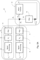
- FIG. 5A shows an example of a blade pitch controller 30 for a floating wind turbine using converters in the form of proportional integral (PI) controllers 31, 33 and 35.
- This blade pitch controller 30 also comprises a standard controller 34 and an active damping controller 32 similar to the controller 10 of Fig. 4 .
- This particular controller 30 uses a PI controller for each of the first and second damping control loops 36, 38 and a PI controller 35 for the standard blade pitch control means 34.
- the first damping control loop 36 uses a first active damping gain K p , represented as a first active damping gain block 37, which operates on a signal processed from the first measured or estimated velocity v p of the wind turbine before being operated on by a first PI controller 31.
- the first PI controller 31 comprises processing circuitry that is capable of converting an output from the first active damping gain block 37 in order to produce a first additional blade pitch adjustment ⁇ 2 .
- the second damping control loop 38 uses a second active damping gain K s , represented as a second active damping gain block 39, which operates on a signal processed from the second measured or estimated velocity v s of the wind turbine before being operated on by a second PI controller 33.
- the second PI controller 38 comprises processing circuitry that is capable of converting an output from the second active damping gain block 39 in order to produce a second additional blade pitch adjustment ⁇ 3 .
- the additional blade pitch adjustments ⁇ 2 and ⁇ 3 are combined with the blade pitch adjustment ⁇ 1 from the standard controller 34 to provide a total blade pitch adjustment ⁇ ref that is used to control the wind turbine so as to damp the first and second motions and cause the rotor speed ⁇ r to tend towards the target rotor speed ⁇ ref 0 . This is so as to reduce the forces on the wind turbine structure and mooring system whilst maximising power output for the given wind speed.
- the controller 30 is operable in the manner described at or above rated wind speed.
- FIG. 5B An alternate controller 40 is shown in Figure 5B .
- This is similar to the controller 30 shown in Figure 5A except it uses a single PI controller 41 for the first and second control loops of the active damping controller 42 rather than two as shown in Figure 5A .
- Figure 5B shows a standard controller 44 and an active damping controller 42, wherein the active damping controller 42 comprises the single PI controller 41, a first and second signal processing blocks 46, 48 and a first and second active damping gain blocks 47, 49.
- the standard controller 44 is configured to combine the standard blade pitch adjustment ⁇ 1 with a combined additional blade pitch adjustment ⁇ 4 , where the combined additional blade pitch adjustment ⁇ 4 is the sum of the first additional blade pitch adjustment ⁇ 2 and the second additional blade pitch adjustment ⁇ 3 .
- the combination of the standard blade pitch adjustment ⁇ 1 and the combined additional blade pitch adjustment ⁇ 4 provides the total blade pitch adjustment ⁇ ref .
- the alternate controller 40 is operable in the manner described at or above the rated wind speed.
- controllers 10, 30, and 40 of Figures 4 , 5A , and 5B are illustrated as blade pitch controllers they may additionally or alternatively calculate a generator torque adjustment that can be used to control the wind turbine so as to tend the actual rotor speed ⁇ r towards the target rotor speed ⁇ ref 0 whilst damping the first and second motions. This can also have the effect of reducing the forces on the wind turbine structure and mooring system whilst maximising power output for the given wind speed.
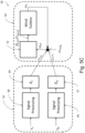
- FIG. 5C Another floating wind turbine controller 50 for damping a first motion and a second motion of different frequencies is shown in Figure 5C .
- This also comprises a standard controller 54 and an active damping controller 52.
- This controller 50 receives an input of the first motion v p (which may be a measured or estimated velocity of the wind turbine in a first frequency range) and processes this using the signal processing 56 and active damping gain K p 57 to convert it to a first additional rotor speed signal ⁇ ref 1 .
- the controller 50 also receives an input of the second motion v s (which may be a measured or estimated velocity of the wind turbine in a second frequency range) and processes this using the signal processing 58 and active damping gain K s 59 to convert it to a second additional rotor speed signal ⁇ ref 2 .
- ⁇ ref 1 and ⁇ ref 2 are outputs that are for damping the first motion and the second motion respectively.
- the signal processing 56 and 58 may each be tailored to the frequency range of concern for that control loop.
- the controller 50 is operable in the manner described at or above the rated wind speed.
- the additional rotor speed signals ⁇ ref 1 and ⁇ ref 2 for damping the first and second motions are combined with the target rotor speed signal ⁇ ref 0 and the actual rotor speed ⁇ r is subtracted to provide a rotor speed error ⁇ error .
- the rotor speed error ⁇ error is converted using the convertor 51 to a blade pitch adjustment signal ⁇ ref and/or a generator torque adjustment signal ⁇ gref that is/are for controlling the floating wind turbine.
- the convertor 51 may be any known means for converting a rotor speed signal to a blade pitch adjustment signal and/or generator torque signal such as a PI controller, a PID controller, a transfer function, a non-linear equation and/or some other wind turbine control system.
- the blade pitch adjustment signal ⁇ ref and/or the generator torque adjustment signal ⁇ ref can be used to control the wind turbine so as to tend the actual rotor speed ⁇ r towards the target rotor speed ⁇ ref 0 , whilst also damping the first and second motions. This can lead to reducing the forces on the wind turbine structure and mooring system whilst maximising power output for the given wind speed.
- the controller 50 of Figure 5C uses one converter 51 with inputs from the active damping controller 52 and the standard controller 54.
- the common features between the various exemplary controllers for a floating wind turbine are that the controller comprises an active damping controller and a standard controller.
- the active damping controller receives an input of the first motion and a separate input of the second motion which have different frequencies.
- These motions are rigid body motions, in particular axial motions such as pitch and/or surge.
- the inputs may be measurements and/or estimates of the velocity of the motions.
- the inputs may be based on the outputs from different sensors. For example, the velocity of a first, higher frequency motion may be based on the output from a motion sensor provided on the floating wind turbine.
- the velocity of a second, lower frequency motion may be based on the output from a differential global positioning system.
- the active damping controller calculates one or more outputs (e.g. either two separate outputs or a combined output) that are for causing the damping of the first and second motions.
- the outputs may be one or more additional rotor speed signals, blade pitch adjustment signals and/or generator torque adjustment signals.
- Figures 6 and 7 show the results of a simulation to help illustrate the benefits of wind turbine control that accounts for motions of different frequencies.
- Figure 6 shows the surge motions for a floating wind turbine with a known controller and with a controller that accounts for motions of two different frequencies (in this case higher frequency pitch motions and lower frequency surge motions).
- Figure 7 shows the mooring line tension in the highest loaded mooring line from the same simulation. The simulation compares scenarios where the floating wind turbine uses a blade pitch controller with active damping for pitch motions only with a floating wind turbine having a controller with active damping for higher frequency pitch motions and lower frequency surge motions.
- Figures 6 and 7 depict a snapshot of the simulation between 700 and 1700 seconds, where the total length of the simulation was 2700 seconds. Parameters of the simulation included that the mean wind speed was 14 ms -1 , there was a turbulence intensity of 8.9%, significant wave heights were set to 1.8m, and the characteristic peak period was 13.8 s.
Landscapes
- Engineering & Computer Science (AREA)
- Combustion & Propulsion (AREA)
- Mechanical Engineering (AREA)
- Chemical & Material Sciences (AREA)
- General Engineering & Computer Science (AREA)
- Life Sciences & Earth Sciences (AREA)
- Sustainable Development (AREA)
- Sustainable Energy (AREA)
- Ocean & Marine Engineering (AREA)
- Physics & Mathematics (AREA)
- Fluid Mechanics (AREA)
- Architecture (AREA)
- Civil Engineering (AREA)
- Structural Engineering (AREA)
- Wind Motors (AREA)
- Connection Of Motors, Electrical Generators, Mechanical Devices, And The Like (AREA)
Claims (20)
- Steuereinheit (10; 30; 40; 50) für eine schwimmende Windkraftanlage, die einen Rotor mit einer Vielzahl von Rotorblättern umfasst, die mit einem Generator verbunden sind, wobei die Steuereinheit Folgendes umfasst:eine aktive Dämpfungssteuereinheit (12; 32; 42; 52) zum Berechnen einer oder mehrerer Ausgaben zum Dämpfen sowohl einer ersten Bewegung der schwimmenden Windkraftanlage in einem ersten Frequenzbereich als auch einer zweiten Bewegung der schwimmenden Windkraftanlage in einem zweiten Frequenzbereich, basierend auf einer Eingabe der ersten Bewegung und einer Eingabe der zweiten Bewegung, wobei die erste Bewegung eine Starrkörperbewegung ist und die zweite Bewegung eine Starrkörperbewegung ist;wobei die aktive Dämpfungssteuereinheit einen ersten Regelkreis (16; 36) und einen zweiten Regelkreis (18; 38) umfasst, wobei der erste Regelkreis die Eingabe der ersten Bewegung empfängt und der zweite Regelkreis die Eingabe der zweiten Bewegung empfängt,wobei die aktive Dämpfungssteuereinheit einen Tiefpassfilter umfasst, wobei eine erste Tiefpassfilterfrequenz für den ersten Regelkreis und eine zweite Tiefpassfilterfrequenz für den zweiten Regelkreis gemäß dem ersten Frequenzbereich beziehungsweise dem zweiten Frequenzbereich eingestellt werden, undwobei die Steuereinheit (10; 30; 40; 50) dazu eingerichtet ist, eine Ausgabe zum Steuern eines Blattwinkels eines oder mehrerer der Vielzahl von Rotorblättern und/oder zum Steuern eines Drehmoments des Generators basierend auf einer tatsächlichen Rotordrehzahl, einer Zielrotordrehzahl und der einen oder den mehreren Ausgaben der aktiven Dämpfungssteuereinheit zu berechnen, sodass sowohl die erste Bewegung als auch die zweite Bewegung gedämpft werden.
- Steuereinheit (10; 30; 40; 50) nach Anspruch 1, wobei die erste Bewegung Nick- und/oder Stoßbewegungen in dem ersten Frequenzbereich umfasst und die zweite Bewegung Nick- und/oder Stoßbewegungen in dem zweiten Frequenzbereich umfasst, wobei der erste Frequenzbereich höher als der zweite Frequenzbereich ist.
- Steuereinheit (10; 30; 40; 50) nach Anspruch 1 oder 2, wobei die Eingabe der ersten Bewegung eine gemessene oder geschätzte Geschwindigkeit der ersten Bewegung ist und die Eingabe der zweiten Bewegung eine gemessene oder geschätzte Geschwindigkeit der zweiten Bewegung ist.
- Steuereinheit (10; 30; 40; 50) nach Anspruch 1, 2 oder 3, wobei die Eingabe der ersten Bewegung unter Verwendung einer Ausgabe eines ersten Sensors gemessen und/oder geschätzt wird und die Eingabe der zweiten Bewegung unter Verwendung einer Ausgabe eines zweiten Sensors gemessen und/oder geschätzt wird.
- Steuereinheit (10; 30; 40; 50) nach Anspruch 4, wobei der erste Sensor ein Bewegungssensor ist und/oder der zweite Sensor ein globaler Positionierungssensor ist.
- Steuereinheit (10; 30; 40; 50) nach einem vorstehenden Anspruch, wobei die Ausgabe zum Dämpfen der ersten Bewegung und/oder der zweiten Bewegung eines oder mehrere eines zusätzlichen Rotordrehzahlreferenzsignals, einer zusätzlichen Blattwinkeleinstellung und/oder einer zusätzlichen Generatordrehmomenteinstellung umfasst.
- Steuereinheit (10; 30; 40; 50) nach einem vorstehenden Anspruch, wobei die Ausgabe zum Steuern des Blattwinkels des einen oder der mehreren der Vielzahl von Rotorblättern eine Gesamtblattwinkeleinstellung umfasst, und/oder wobei die Ausgabe zum Steuern des Drehmoments des Generators eine Gesamtgeneratordrehmomenteinstellung umfasst.
- Schwimmende Windkraftanlage, die einen Rotor mit einer Vielzahl von Rotorblättern, die mit einem Generator verbunden sind, und die Steuereinheit (10; 30; 40; 50) nach einem vorstehenden Anspruch umfasst.
- Verfahren zum Steuern einer Blattneigung und/oder eines Generatordrehmoments einer schwimmenden Windkraftanlage, wobei die schwimmende Windkraftanlage einen Rotor mit einer Vielzahl von Rotorblättern umfasst, die mit einem Generator verbunden sind, wobei das Verfahren Folgendes umfasst:Empfangen, in einem ersten Regelkreis, einer Eingabe einer ersten Bewegung der schwimmenden Windkraftanlage in einem ersten Frequenzbereich, wobei eine erste Tiefpassfilterfrequenz für den ersten Regelkreis gemäß dem ersten Frequenzbereich eingestellt wird und wobei die erste Bewegung eine Starrkörperbewegung ist;Empfangen, in einem zweiten Regelkreis, einer Eingabe einer zweiten Bewegung der schwimmenden Windkraftanlage in einem zweiten Frequenzbereich, wobei eine zweite Tiefpassfilterfrequenz für den zweiten Regelkreis gemäß dem zweiten Frequenzbereich eingestellt wird und wobei die zweite Bewegung eine Starrkörperbewegung ist;Berechnen einer oder mehrerer Dämpfungsausgaben zum Dämpfen sowohl der ersten Bewegung als auch der zweiten Bewegung basierend auf der Eingabe der ersten Bewegung und der Eingabe der zweiten Bewegung; undBerechnen einer Ausgabe zum Steuern eines Blattwinkels eines oder mehrerer der Vielzahl von Rotorblättern und/oder zum Steuern des Drehmoments des Generators basierend auf einer tatsächlichen Rotordrehzahl, einer Zielrotordrehzahl und der einen oder den mehreren Dämpfungsausgaben, sodass sowohl die erste Bewegung als auch die zweite Bewegung gedämpft werden.
- Verfahren nach Anspruch 9, wobei die erste Bewegung Nick- und/oder Stoßbewegungen in dem ersten Frequenzbereich umfasst und die zweite Bewegung Nick- und/oder Stoßbewegungen in dem zweiten Frequenzbereich umfasst, wobei der erste Frequenzbereich höher als der zweite Frequenzbereich ist.
- Verfahren nach Anspruch 9 oder 10, wobei die Eingabe der ersten Bewegung eine gemessene oder geschätzte Geschwindigkeit der ersten Bewegung ist und die Eingabe der zweiten Bewegung eine gemessene oder geschätzte Geschwindigkeit der zweiten Bewegung ist.
- Verfahren nach Anspruch 9, 10 oder 11, wobei die Eingabe der ersten Bewegung unter Verwendung der Ausgabe eines ersten Sensors gemessen und/oder geschätzt wird und die Eingabe der zweiten Bewegung unter Verwendung der Ausgabe eines zweiten Sensors gemessen und/oder geschätzt wird.
- Verfahren ach Anspruch 12, wobei der erste Sensor ein Bewegungssensor ist und/oder der zweite Sensor ein globaler Positionierungssensor ist.
- Verfahren nach einem der Ansprüche 9 bis 13, wobei die eine oder mehreren Dämpfungsausgaben eines oder mehrere eines zusätzlichen Rotordrehzahlreferenzsignals, einer zusätzlichen Blattwinkeleinstellung und/oder einer zusätzlichen Generatordrehmomenteinstellung umfassen.
- Verfahren nach einem der Ansprüche 9 bis 14, wobei die Ausgabe zum Steuern eines Blattwinkels eines oder mehrerer der Vielzahl von Rotorblättern eine Gesamtblattwinkeleinstellung umfasst, und/oder wobei die Ausgabe zum Steuern des Drehmoments des Generators eine Gesamtgeneratordrehmomenteinstellung umfasst.
- Verfahren nach einem der Ansprüche 9 bis 15, wobei das Verfahren unter Verwendung der Steuereinheit nach einem der Ansprüche 1 bis 7 durchgeführt wird.
- Computerprogrammprodukt, das Anweisungen umfasst, die, wenn sie auf einer Verarbeitungsschaltung für eine schwimmende Windkraftanlage ausgeführt werden, die Verarbeitungsschaltung dazu konfigurieren, das Verfahren nach einem der Ansprüche 11 bis 16 durchzuführen.
- Steuereinheit, Computerprogrammprodukt oder Verfahren nach einem vorstehenden Anspruch, wobei die Dämpfung bei oder über der Nennwindgeschwindigkeit erfolgt.
- Steuereinheit nach einem der Ansprüche 1 bis 7, wobei die erste Tiefpassfilterfrequenz


- Verfahren nach einem der Ansprüche 9 bis 16, wobei die erste Tiefpassfilterfrequenz


Applications Claiming Priority (2)
| Application Number | Priority Date | Filing Date | Title |
|---|---|---|---|
| GB1919010.7A GB2591732C (en) | 2019-12-20 | 2019-12-20 | Wind turbine control |
| PCT/NO2020/000006 WO2021125966A1 (en) | 2019-12-20 | 2020-12-21 | Wind turbine control |
Publications (3)
| Publication Number | Publication Date |
|---|---|
| EP4077920A1 EP4077920A1 (de) | 2022-10-26 |
| EP4077920A4 EP4077920A4 (de) | 2024-02-28 |
| EP4077920B1 true EP4077920B1 (de) | 2025-07-02 |
Family
ID=69322801
Family Applications (1)
| Application Number | Title | Priority Date | Filing Date |
|---|---|---|---|
| EP20902394.4A Active EP4077920B1 (de) | 2019-12-20 | 2020-12-21 | Windturbinensteuerung |
Country Status (12)
| Country | Link |
|---|---|
| US (1) | US12129825B2 (de) |
| EP (1) | EP4077920B1 (de) |
| JP (1) | JP7440636B2 (de) |
| KR (1) | KR102644711B1 (de) |
| CN (1) | CN115135871B (de) |
| AU (1) | AU2020410032C1 (de) |
| BR (1) | BR112022012048B1 (de) |
| CA (1) | CA3165494A1 (de) |
| ES (1) | ES3041087T3 (de) |
| GB (1) | GB2591732C (de) |
| PT (1) | PT4077920T (de) |
| WO (1) | WO2021125966A1 (de) |
Families Citing this family (3)
| Publication number | Priority date | Publication date | Assignee | Title |
|---|---|---|---|---|
| DE102019105296A1 (de) * | 2019-03-01 | 2020-09-03 | Wobben Properties Gmbh | Verfahren zum Betreiben einer Windenergieanlage, Reglerstruktur, Windenergieanlage und Windpark |
| CN116696668A (zh) * | 2022-02-28 | 2023-09-05 | 金风科技股份有限公司 | 一种风力发电机的振动控制方法和相关装置 |
| EP4686827A1 (de) * | 2024-08-02 | 2026-02-04 | Siemens Gamesa Renewable Energy A/S | Bewegungssteuerung einer offshore-windturbine |
Family Cites Families (23)
| Publication number | Priority date | Publication date | Assignee | Title |
|---|---|---|---|---|
| GB2442719A (en) * | 2006-10-10 | 2008-04-16 | Iti Scotland Ltd | Wave and wind power generation system |
| ES2552162T5 (es) * | 2007-11-26 | 2020-03-02 | Siemens Ag | Método de amortiguación de vibraciones de torre de una turbina eólica y sistema de control de inclinación |
| DK2107236T3 (en) * | 2008-04-02 | 2015-02-02 | Siemens Ag | Method for attenuating tower vibration of a wind turbine and wind turbine control system |
| GB2466649B (en) | 2008-12-30 | 2014-01-29 | Hywind As | Blade pitch control in a wind turbine installation |
| GB0907132D0 (en) * | 2009-04-24 | 2009-06-03 | Statoilhydro Asa | Wave energy extraction |
| US8169098B2 (en) * | 2010-12-22 | 2012-05-01 | General Electric Company | Wind turbine and operating same |
| EP2489872B1 (de) * | 2011-02-15 | 2013-03-20 | SSB Wind Systems GmbH & Co. KG | Schaufellastverringerung für Windrad |
| WO2013065323A1 (ja) * | 2011-11-04 | 2013-05-10 | 独立行政法人海上技術安全研究所 | 浮体式洋上風力発電施設の制御装置 |
| EP2620639B1 (de) * | 2012-01-30 | 2016-01-27 | ALSTOM Renewable Technologies | Verfahren zur Dämpfung von Schwankungen in einer Windturbine |
| JP5443629B1 (ja) * | 2012-08-28 | 2014-03-19 | 三井造船株式会社 | 洋上風力発電装置および風力タービン制御装置 |
| GB201223088D0 (en) * | 2012-12-20 | 2013-02-06 | Statoil Asa | Controlling motions of floating wind turbines |
| JP6388759B2 (ja) * | 2013-05-29 | 2018-09-12 | エムエイチアイ ヴェスタス オフショア ウィンド エー/エス | 浮体式風力発電装置 |
| CN103541861B (zh) * | 2013-10-30 | 2016-02-24 | 新疆金风科技股份有限公司 | 浮动式风电机组塔架负阻尼抑制系统和方法 |
| ES2694009T3 (es) * | 2013-12-09 | 2018-12-17 | Vestas Wind Systems A/S | Método de operación de una turbina eólica |
| EP3080445A1 (de) * | 2013-12-09 | 2016-10-19 | Vestas Wind Systems A/S | Bekämpfung von turmschwankungen einer leerlaufenden windturbine |
| DK201470481A1 (en) * | 2014-08-13 | 2015-08-17 | Vestas Wind Sys As | Improvements relating to wind turbine operation |
| JP6352778B2 (ja) * | 2014-11-17 | 2018-07-04 | 三菱重工業株式会社 | 浮体式風力発電装置及びその運転方法 |
| JP6506664B2 (ja) * | 2015-09-10 | 2019-04-24 | 株式会社日立製作所 | 風力発電システムまたは風力発電システムの制御方法 |
| KR102638423B1 (ko) * | 2016-11-29 | 2024-02-19 | 하이윈드 에이에스 | 부유식 풍력 터빈 구조체를 위한 제어 시스템 |
| ES2951472T3 (es) * | 2017-02-10 | 2023-10-23 | Vestas Wind Sys As | Reducción de vibración de movimiento de góndola basada en posición |
| US11098695B2 (en) | 2017-03-21 | 2021-08-24 | Vestas Wind Systems A/S | System and method to manage torsional oscillation of a wind turbine tower |
| EP3667074A1 (de) * | 2018-12-13 | 2020-06-17 | Siemens Gamesa Renewable Energy A/S | Vorrichtung und verfahren zur dämpfung von vorwärts- und rückwärtsbewegungen eines turms einer windturbine |
| DK4102057T3 (da) | 2021-06-11 | 2026-02-09 | Wobben Properties Gmbh | Fremgangsmåde til styring af rotorhastigheden af en vindmølle |
-
2019
- 2019-12-20 GB GB1919010.7A patent/GB2591732C/en active Active
-
2020
- 2020-12-21 BR BR112022012048-6A patent/BR112022012048B1/pt active IP Right Grant
- 2020-12-21 US US17/757,166 patent/US12129825B2/en active Active
- 2020-12-21 WO PCT/NO2020/000006 patent/WO2021125966A1/en not_active Ceased
- 2020-12-21 CN CN202080096894.2A patent/CN115135871B/zh active Active
- 2020-12-21 PT PT209023944T patent/PT4077920T/pt unknown
- 2020-12-21 AU AU2020410032A patent/AU2020410032C1/en active Active
- 2020-12-21 JP JP2022537286A patent/JP7440636B2/ja active Active
- 2020-12-21 ES ES20902394T patent/ES3041087T3/es active Active
- 2020-12-21 KR KR1020227025142A patent/KR102644711B1/ko active Active
- 2020-12-21 CA CA3165494A patent/CA3165494A1/en active Pending
- 2020-12-21 EP EP20902394.4A patent/EP4077920B1/de active Active
Also Published As
| Publication number | Publication date |
|---|---|
| BR112022012048B1 (pt) | 2023-12-12 |
| GB2591732B (en) | 2022-03-16 |
| WO2021125966A1 (en) | 2021-06-24 |
| US20230054921A1 (en) | 2023-02-23 |
| US12129825B2 (en) | 2024-10-29 |
| AU2020410032A1 (en) | 2022-07-28 |
| AU2020410032C1 (en) | 2024-01-18 |
| CN115135871A (zh) | 2022-09-30 |
| JP7440636B2 (ja) | 2024-02-28 |
| KR20220117316A (ko) | 2022-08-23 |
| EP4077920A4 (de) | 2024-02-28 |
| ES3041087T3 (en) | 2025-11-06 |
| GB201919010D0 (en) | 2020-02-05 |
| PT4077920T (pt) | 2025-09-11 |
| BR112022012048A2 (pt) | 2022-08-30 |
| EP4077920A1 (de) | 2022-10-26 |
| GB2591732A (en) | 2021-08-11 |
| JP2023507394A (ja) | 2023-02-22 |
| GB2591732C (en) | 2026-01-28 |
| CA3165494A1 (en) | 2021-06-24 |
| AU2020410032B2 (en) | 2023-05-11 |
| CN115135871B (zh) | 2024-01-02 |
| KR102644711B1 (ko) | 2024-03-06 |
Similar Documents
| Publication | Publication Date | Title |
|---|---|---|
| US10087913B2 (en) | Controlling motions of floating wind turbines | |
| EP2370694B1 (de) | Blattverstellungssteuerung bei einer windkraftanlage | |
| KR102638423B1 (ko) | 부유식 풍력 터빈 구조체를 위한 제어 시스템 | |
| JP5819286B2 (ja) | 風力タービン装置の波動エネルギの抽出 | |
| EP4077920B1 (de) | Windturbinensteuerung | |
| US12331723B2 (en) | Floating wind turbine control below rated wind speed | |
| HK1210249B (en) | Controlling motions of floating wind turbines |
Legal Events
| Date | Code | Title | Description |
|---|---|---|---|
| STAA | Information on the status of an ep patent application or granted ep patent |
Free format text: STATUS: THE INTERNATIONAL PUBLICATION HAS BEEN MADE |
|
| PUAI | Public reference made under article 153(3) epc to a published international application that has entered the european phase |
Free format text: ORIGINAL CODE: 0009012 |
|
| STAA | Information on the status of an ep patent application or granted ep patent |
Free format text: STATUS: REQUEST FOR EXAMINATION WAS MADE |
|
| 17P | Request for examination filed |
Effective date: 20220720 |
|
| AK | Designated contracting states |
Kind code of ref document: A1 Designated state(s): AL AT BE BG CH CY CZ DE DK EE ES FI FR GB GR HR HU IE IS IT LI LT LU LV MC MK MT NL NO PL PT RO RS SE SI SK SM TR |
|
| DAV | Request for validation of the european patent (deleted) | ||
| DAX | Request for extension of the european patent (deleted) | ||
| A4 | Supplementary search report drawn up and despatched |
Effective date: 20240130 |
|
| RIC1 | Information provided on ipc code assigned before grant |
Ipc: F03D 13/25 20160101ALI20240124BHEP Ipc: F03D 7/02 20060101AFI20240124BHEP |
|
| STAA | Information on the status of an ep patent application or granted ep patent |
Free format text: STATUS: EXAMINATION IS IN PROGRESS |
|
| 17Q | First examination report despatched |
Effective date: 20241015 |
|
| GRAP | Despatch of communication of intention to grant a patent |
Free format text: ORIGINAL CODE: EPIDOSNIGR1 |
|
| STAA | Information on the status of an ep patent application or granted ep patent |
Free format text: STATUS: GRANT OF PATENT IS INTENDED |
|
| INTG | Intention to grant announced |
Effective date: 20250204 |
|
| GRAS | Grant fee paid |
Free format text: ORIGINAL CODE: EPIDOSNIGR3 |
|
| GRAA | (expected) grant |
Free format text: ORIGINAL CODE: 0009210 |
|
| STAA | Information on the status of an ep patent application or granted ep patent |
Free format text: STATUS: THE PATENT HAS BEEN GRANTED |
|
| AK | Designated contracting states |
Kind code of ref document: B1 Designated state(s): AL AT BE BG CH CY CZ DE DK EE ES FI FR GB GR HR HU IE IS IT LI LT LU LV MC MK MT NL NO PL PT RO RS SE SI SK SM TR |
|
| REG | Reference to a national code |
Ref country code: GB Ref legal event code: FG4D |
|
| REG | Reference to a national code |
Ref country code: CH Ref legal event code: EP |
|
| REG | Reference to a national code |
Ref country code: DE Ref legal event code: R096 Ref document number: 602020054007 Country of ref document: DE |
|
| REG | Reference to a national code |
Ref country code: IE Ref legal event code: FG4D |
|
| REG | Reference to a national code |
Ref country code: PT Ref legal event code: SC4A Ref document number: 4077920 Country of ref document: PT Date of ref document: 20250911 Kind code of ref document: T Free format text: AVAILABILITY OF NATIONAL TRANSLATION Effective date: 20250908 |
|
| REG | Reference to a national code |
Ref country code: SE Ref legal event code: TRGR |
|
| REG | Reference to a national code |
Ref country code: NL Ref legal event code: MP Effective date: 20250702 |
|
| REG | Reference to a national code |
Ref country code: ES Ref legal event code: FG2A Ref document number: 3041087 Country of ref document: ES Kind code of ref document: T3 Effective date: 20251106 |
|
| PG25 | Lapsed in a contracting state [announced via postgrant information from national office to epo] |
Ref country code: NL Free format text: LAPSE BECAUSE OF FAILURE TO SUBMIT A TRANSLATION OF THE DESCRIPTION OR TO PAY THE FEE WITHIN THE PRESCRIBED TIME-LIMIT Effective date: 20250702 |
|
| REG | Reference to a national code |
Ref country code: AT Ref legal event code: MK05 Ref document number: 1809483 Country of ref document: AT Kind code of ref document: T Effective date: 20250702 |
|
| PG25 | Lapsed in a contracting state [announced via postgrant information from national office to epo] |
Ref country code: IS Free format text: LAPSE BECAUSE OF FAILURE TO SUBMIT A TRANSLATION OF THE DESCRIPTION OR TO PAY THE FEE WITHIN THE PRESCRIBED TIME-LIMIT Effective date: 20251102 |
|
| PGFP | Annual fee paid to national office [announced via postgrant information from national office to epo] |
Ref country code: NO Payment date: 20251222 Year of fee payment: 6 |
|
| REG | Reference to a national code |
Ref country code: LT Ref legal event code: MG9D |
|
| PG25 | Lapsed in a contracting state [announced via postgrant information from national office to epo] |
Ref country code: AT Free format text: LAPSE BECAUSE OF FAILURE TO SUBMIT A TRANSLATION OF THE DESCRIPTION OR TO PAY THE FEE WITHIN THE PRESCRIBED TIME-LIMIT Effective date: 20250702 |
|
| PGFP | Annual fee paid to national office [announced via postgrant information from national office to epo] |
Ref country code: PT Payment date: 20251216 Year of fee payment: 6 |
|
| PG25 | Lapsed in a contracting state [announced via postgrant information from national office to epo] |
Ref country code: FI Free format text: LAPSE BECAUSE OF FAILURE TO SUBMIT A TRANSLATION OF THE DESCRIPTION OR TO PAY THE FEE WITHIN THE PRESCRIBED TIME-LIMIT Effective date: 20250702 |
|
| PGFP | Annual fee paid to national office [announced via postgrant information from national office to epo] |
Ref country code: IT Payment date: 20251218 Year of fee payment: 6 |
|
| PG25 | Lapsed in a contracting state [announced via postgrant information from national office to epo] |
Ref country code: HR Free format text: LAPSE BECAUSE OF FAILURE TO SUBMIT A TRANSLATION OF THE DESCRIPTION OR TO PAY THE FEE WITHIN THE PRESCRIBED TIME-LIMIT Effective date: 20250702 |
|
| PGFP | Annual fee paid to national office [announced via postgrant information from national office to epo] |
Ref country code: FR Payment date: 20251217 Year of fee payment: 6 |
|
| PG25 | Lapsed in a contracting state [announced via postgrant information from national office to epo] |
Ref country code: GR Free format text: LAPSE BECAUSE OF FAILURE TO SUBMIT A TRANSLATION OF THE DESCRIPTION OR TO PAY THE FEE WITHIN THE PRESCRIBED TIME-LIMIT Effective date: 20251003 |
|
| PGFP | Annual fee paid to national office [announced via postgrant information from national office to epo] |
Ref country code: SE Payment date: 20251219 Year of fee payment: 6 |
|
| PG25 | Lapsed in a contracting state [announced via postgrant information from national office to epo] |
Ref country code: CZ Free format text: LAPSE BECAUSE OF FAILURE TO SUBMIT A TRANSLATION OF THE DESCRIPTION OR TO PAY THE FEE WITHIN THE PRESCRIBED TIME-LIMIT Effective date: 20250702 |
|
| PGFP | Annual fee paid to national office [announced via postgrant information from national office to epo] |
Ref country code: IE Payment date: 20251218 Year of fee payment: 6 |
|
| PG25 | Lapsed in a contracting state [announced via postgrant information from national office to epo] |
Ref country code: LV Free format text: LAPSE BECAUSE OF FAILURE TO SUBMIT A TRANSLATION OF THE DESCRIPTION OR TO PAY THE FEE WITHIN THE PRESCRIBED TIME-LIMIT Effective date: 20250702 |
|
| PG25 | Lapsed in a contracting state [announced via postgrant information from national office to epo] |
Ref country code: BG Free format text: LAPSE BECAUSE OF FAILURE TO SUBMIT A TRANSLATION OF THE DESCRIPTION OR TO PAY THE FEE WITHIN THE PRESCRIBED TIME-LIMIT Effective date: 20250702 Ref country code: PL Free format text: LAPSE BECAUSE OF FAILURE TO SUBMIT A TRANSLATION OF THE DESCRIPTION OR TO PAY THE FEE WITHIN THE PRESCRIBED TIME-LIMIT Effective date: 20250702 |
|
| PG25 | Lapsed in a contracting state [announced via postgrant information from national office to epo] |
Ref country code: RS Free format text: LAPSE BECAUSE OF FAILURE TO SUBMIT A TRANSLATION OF THE DESCRIPTION OR TO PAY THE FEE WITHIN THE PRESCRIBED TIME-LIMIT Effective date: 20251002 |
|
| PG25 | Lapsed in a contracting state [announced via postgrant information from national office to epo] |
Ref country code: RO Free format text: LAPSE BECAUSE OF FAILURE TO SUBMIT A TRANSLATION OF THE DESCRIPTION OR TO PAY THE FEE WITHIN THE PRESCRIBED TIME-LIMIT Effective date: 20250702 |