EP4077892B1 - Method of making a thermal insulation structure - Google Patents
Method of making a thermal insulation structure Download PDFInfo
- Publication number
- EP4077892B1 EP4077892B1 EP20828318.4A EP20828318A EP4077892B1 EP 4077892 B1 EP4077892 B1 EP 4077892B1 EP 20828318 A EP20828318 A EP 20828318A EP 4077892 B1 EP4077892 B1 EP 4077892B1
- Authority
- EP
- European Patent Office
- Prior art keywords
- pollution control
- inorganic
- mat material
- inorganic adhesive
- casing
- Prior art date
- Legal status (The legal status is an assumption and is not a legal conclusion. Google has not performed a legal analysis and makes no representation as to the accuracy of the status listed.)
- Active
Links
Images


Classifications
-
- F—MECHANICAL ENGINEERING; LIGHTING; HEATING; WEAPONS; BLASTING
- F01—MACHINES OR ENGINES IN GENERAL; ENGINE PLANTS IN GENERAL; STEAM ENGINES
- F01N—GAS-FLOW SILENCERS OR EXHAUST APPARATUS FOR MACHINES OR ENGINES IN GENERAL; GAS-FLOW SILENCERS OR EXHAUST APPARATUS FOR INTERNAL-COMBUSTION ENGINES
- F01N3/00—Exhaust or silencing apparatus having means for purifying, rendering innocuous, or otherwise treating exhaust
- F01N3/08—Exhaust or silencing apparatus having means for purifying, rendering innocuous, or otherwise treating exhaust for rendering innocuous
- F01N3/10—Exhaust or silencing apparatus having means for purifying, rendering innocuous, or otherwise treating exhaust for rendering innocuous by thermal or catalytic conversion of noxious components of exhaust
- F01N3/24—Exhaust or silencing apparatus having means for purifying, rendering innocuous, or otherwise treating exhaust for rendering innocuous by thermal or catalytic conversion of noxious components of exhaust characterised by constructional aspects of converting apparatus
- F01N3/28—Construction of catalytic reactors
- F01N3/2839—Arrangements for mounting catalyst support in housing, e.g. with means for compensating thermal expansion or vibration
- F01N3/2853—Arrangements for mounting catalyst support in housing, e.g. with means for compensating thermal expansion or vibration using mats or gaskets between catalyst body and housing
- F01N3/2864—Arrangements for mounting catalyst support in housing, e.g. with means for compensating thermal expansion or vibration using mats or gaskets between catalyst body and housing the mats or gaskets comprising two or more insulation layers
-
- F—MECHANICAL ENGINEERING; LIGHTING; HEATING; WEAPONS; BLASTING
- F01—MACHINES OR ENGINES IN GENERAL; ENGINE PLANTS IN GENERAL; STEAM ENGINES
- F01N—GAS-FLOW SILENCERS OR EXHAUST APPARATUS FOR MACHINES OR ENGINES IN GENERAL; GAS-FLOW SILENCERS OR EXHAUST APPARATUS FOR INTERNAL-COMBUSTION ENGINES
- F01N3/00—Exhaust or silencing apparatus having means for purifying, rendering innocuous, or otherwise treating exhaust
- F01N3/08—Exhaust or silencing apparatus having means for purifying, rendering innocuous, or otherwise treating exhaust for rendering innocuous
- F01N3/10—Exhaust or silencing apparatus having means for purifying, rendering innocuous, or otherwise treating exhaust for rendering innocuous by thermal or catalytic conversion of noxious components of exhaust
- F01N3/24—Exhaust or silencing apparatus having means for purifying, rendering innocuous, or otherwise treating exhaust for rendering innocuous by thermal or catalytic conversion of noxious components of exhaust characterised by constructional aspects of converting apparatus
- F01N3/28—Construction of catalytic reactors
- F01N3/2839—Arrangements for mounting catalyst support in housing, e.g. with means for compensating thermal expansion or vibration
- F01N3/2853—Arrangements for mounting catalyst support in housing, e.g. with means for compensating thermal expansion or vibration using mats or gaskets between catalyst body and housing
- F01N3/2871—Arrangements for mounting catalyst support in housing, e.g. with means for compensating thermal expansion or vibration using mats or gaskets between catalyst body and housing the mats or gaskets having an additional, e.g. non-insulating or non-cushioning layer, a metal foil or an adhesive layer
Definitions
- the present disclosure relates to a method of producing a thermal insulation structure (e.g., a pollution control apparatus).
- a thermal insulation structure e.g., a pollution control apparatus
- Exhaust gas from an automobile engine contains carbon monoxide (CO), hydrocarbons (HC), nitrogen oxides (NOx), and the like.
- Exhaust gas from a diesel engine further contains a particulate matter such as soot.
- an exhaust gas cleaning system using a ceramic catalytic converter or a diesel particulate filter (DPF) is known.
- DPF diesel particulate filter
- mounting of a gasoline particulate filter (GPF) has also been investigated. These devices are generally called a pollution control apparatus.
- a pollution control apparatus e.g., a ceramic catalytic converter
- a pollution control element e.g., a honeycomb-shaped catalyst carrier made of ceramic
- a casing made of metal that encases the pollution control element
- a holding material packed in a gap between an outer circumferential surface of the pollution control element and an inner surface of the casing.
- the holding material holds the pollution control element in the casing to prevent mechanical shock due to impact, vibration, and the like from being inadvertently applied to the pollution control element.
- the holding material prevents the pollution control element from moving and breaking in the casing, providing desirable effects throughout an operating life of the pollution control element.
- This type of the holding material is also commonly called a mounting material.
- Such a holding material is generally a mat-like material including a single layer or multiple layers, and is used by being wrapped around the pollution control element.
- the holding material generally includes inorganic materials such as inorganic fibers as a main constituent from the viewpoint of achieving excellent thermal insulation and heat resistance.
- inorganic materials such as inorganic fibers as a main constituent from the viewpoint of achieving excellent thermal insulation and heat resistance.
- Such a holding material (mounting material) is described, for example, in Patent Documents JP 57-61686 A , JP 2002-66331 A , and JP 2006-223920 A .
- WO 2008/154078 A1 describes a securable mounting material comprises: a mounting material comprising inorganic fibers and having a major surface; and a layer of thermally activatable adhesive inwardly disposed on the inorganic fibers proximate the major surface.
- the thermally activatable adhesive comprises at least one compound represented by the formula: (M m+ ) d ((Z p O q (OH) r ) n- ) e (H 2 O) f , where M represents a cationic species other than H+; O represents oxygen; Z represents boron or phosphorus; f is a real number greater than or equal to zero; d, n, q, and r are integers greater than or equal to zero; e, m, and p are integers greater than or equal to one; and d times m equals e times n.
- a method of making the mounting material is also described.
- EP 2 363 582 A1 describes a multilayer mounting mat operatively adapted for use in mounting a pollution control element in a pollution control device comprises a first layer, a second layer, and an adhesive sandwiched therebetween so as to bond together a major surface of the first layer to a major surface of the second layer, the adhesive comprising at least one of inorganic colloidal particles having an average diameter less than about 300 nm and an inorganic water-soluble salt.
- a holding material in the art of mounting pollution control elements in the casing of a pollution control apparatus, has been designed to prevent a shift in position during use mainly by a compression repulsive force and friction force of the holding material. Most such holding material exhibit a coefficient of friction in the range of from 0.4 to 0.5 at 600°C, at the surface in contact with one or both of the casing or pollution control element.
- a technique wherein a holding material, after it is encased together with a pollution control element in a casing, holds the pollution control element by a compression repulsive force on a surface of the other member (i.e., an inner surface of the casing and/or an outer surface of the pollution control element) with which the holding material is in contact such that the pollution control element does not move from a predetermined position.
- An object of the present disclosure is to provide a method of producing a thermal insulation structure for use under a heating environment.
- the present disclosure relates to a method of producing a thermal insulation structure.
- the method comprises: providing a first member comprising a first surface having a temperature potentially reaching 200°C or higher; providing a second member comprising a second surface disposed opposite to the first surface of the first member; coating a solution containing an inorganic adhesive onto at least a part of at least one of the first surface of the first member and the second surface of the second member; and drying the solution so that the inorganic adhesive is substantially dry on and bonded to at least part of at least one of the first surface and the second surface.
- the method further comprises disposing a mat material between the first surface of the first member and the second surface of the second member so that the mat material contacts at least part of the substantially dry inorganic adhesive.
- the thermal insulation structure is a pollution control apparatus, with the first member being pollution control element, the second member being a casing, the pollution control element being provided in the casing, and the mat material is disposed between the pollution control element and the casing.
- the inorganic adhesive comprises an alkali metal silicate selected from the group consisting of sodium silicate, potassium silicate and lithium silicate, and the inorganic adhesive exhibits adhesiveness upon being heated.
- the method of producing a thermal insulation structure of the present invention comprises:
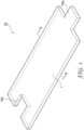
- FIG. 1 is a perspective view illustrating an example of a mat material configured to be wrapped around a pollution control element 30 having a round cylindrical or elliptical cylindrical outer shape and to mount and thermally insulate the pollution control element 30 in a casing 20 (refer to FIG. 2 ).
- the mat material 10 has a length that is in accordance with the length of the outer circumference of the pollution control element 30.
- the mat material 10 has a convex part 10a on one end, and a concave part 10b on the other end, for example, and has a shape such that the convex or tong part 10a and the concave or groove part 10b mutually mate when the mat material 10 is wrapped around the pollution control element 30.
- other shapes such as an L shape are also possible, and the shape for the mating is not particularly limited.
- one or each of the structure members is obtained with a surface layer 5 formed on at least one surface thereof.
- a surface layer 5 (area containing an inorganic adhesive) is provided on a first surface 34 of a first member 30 (e.g., an outer surface of a pollution control element 30), on a second surface 24 of a second member 20 (e.g., an inner surface of a pollution control apparatus casing 20), or on both surfaces 34 and 24.
- each surface layer 5 can be desirable for each surface layer 5 to have a thickness in the range of from about 5 to about 15 mm. As can be seen e.g. in FIG.
- a mat material 10 is disposed between the member surfaces 24 and 34 of members 20 and 30, respectively, with each member having adhesive surface layer 5 disposed between the mat material and the corresponding member.
- the mat material 10 includes inorganic fibers, which can have a diameter (e.g., an average diameter) in the range of from about 3 to about 10 ⁇ m.
- the mat material can also include other components compounded as necessary.
- Each surface layer 5 includes an inorganic adhesive exhibiting adhesiveness upon being heated, and optionally other components compounded as necessary. Note in some cases that the surface layer 5 is only on one surface of its corresponding member. Alternatively, the surface layer 5 can be on only a portion or part of the area of one surface or both surfaces 24 and 34.
- FIG 3 illustrates a state, in which a surface layer 5 is laminated on and adhered to one or both of the surface 24 and the surface 34 of members 20 and 30 respectively, but upon heating the inorganic adhesive each surface layer 5 is also adhered to and impregnated into the body portion of the mat material 10 as described below.
- the surface layer(s) 5 contains an inorganic adhesive exhibiting adhesiveness upon being heated.
- Inorganic adhesives described herein include those providing not only adhesion by the formation of reaction products with other members upon being heated, but also adhesion due to anchoring effect (fixed or adhered state), resulting from fluidity exhibited by an inorganic adhesive of the surface layer 5 upon being heated, and penetration into contact surfaces of the mat material 10 or other members.
- the temperature at which adhesiveness is exhibited is not limited, but adhesiveness is exhibited, for example, at 200°C or higher, 300°C or higher, or 600°C or higher.
- the mat material 10 is arranged in a sandwiched state between the two members and is allowed to stand under a temperature condition of 600°C for 1 hour.
- the mat material 10 exhibits adhesiveness to other members.
- Exhibition of adhesiveness can be visually judged by checking whether a fixed or adhered area is formed between the mat material 10 and one, or the other or both members after the heated mat material 10 is cooled (see FIGS. 5 and 6 ).
- Such adhesiveness can result in the mat material 10 exhibiting a coefficient of friction of 0.75 or higher at 600°C, at the surface in contact with one or both of the first member and second member.
- the inorganic adhesive is generally in a liquid state at ordinary temperature, but the surface layer 5 is substantially dry on a corresponding structure member (e.g., members 20 or 30).
- substantially dry herein refers to, for example, a dry state obtained by a drying process after coating the inorganic adhesive; for such a dry state, the mass loss after heating the mat material 10 at 120°C for 30 min is within about 5% based on the mass of the mat material 10 before heating.
- the surface layer 5, as being substantially dry has an advantage of excellent workability when assembling the components (e.g., members) of the thermal insulation structure or device.
- the inorganic adhesive includes an alkali metal silicate selected from sodium silicate, potassium silicate, and lithium silicate.
- alkali metal silicate selected from sodium silicate, potassium silicate, and lithium silicate.
- One type of these components may be alone, or combination of two or more types may be used.
- a liquid containing the above-mentioned inorganic adhesive is coated on the surface of either structure member 20 and 30, followed by the drying process to form the surface layer 5.
- the content of the inorganic adhesive (the above-mentioned salts) in the surface layer 5 is, for example, from 1 to 50 g/m 2 , and may be from 2 to 40 g/m 2 or from 5 to 30 g/m 2 .
- the amount of the inorganic adhesive in the surface layer 5 may be set as appropriate depending on adhesiveness required for the mat material 10 to the desired member(s) 20 and/or 30.
- the surface layer 5 may contain inorganic colloidal particles. While various types of fine particles of inorganic materials can be used to form the inorganic colloidal particles, preferred inorganic materials include metal oxides, nitrides, and carbides, as well as materials preferably having heat resistance. For example, preferred examples include, but not limited to, silica, alumina, mullite, zirconia, magnesia, and titania. Examples of other suitable materials include boron nitride and boron carbide. Those inorganic materials may be used individually or in combination of two or more thereof.
- inorganic colloidal particles can be used in various particle sizes in accordance with the type of the inorganic material and the desired friction-improving effect, it is generally preferred that they have an average particle size from about 1 to 100 nm. In a case where the inorganic colloidal particles have an average particle size of less than 1 nm, such inorganic colloidal particles are incapable of forming a friction layer that can contribute to the friction-increasing effect. In contrast, in a case where the inorganic colloidal particles have an average particle size greater than 100 nm, the particles may be too large to appropriately contribute to increasing the friction and result in falling off.
- the average particle size of the inorganic colloidal particles is more preferably in the range from about 10 to 80 nm, and most preferably in the range from about 20 to 50 nm.
- WO 2007/030410 may be referenced.
- the inorganic adhesive may also comprise inorganic fillers such as clays (kaolin), boehmite, titanium dioxide, fumed silica, fumed alumina, precipitated silica, ATH and other compatible common fillers to modify viscosity and absorption properties.
- the inorganic adhesive may also contain humectants such as glycerin, sorbitol, other sugar alcohols, and ethylene glycol. These materials can help plasticize the inorganic adhesive to improve handling properties.
- Compatible dyes and pigments may also be incorporated to help identify the presence and location of the inorganic adhesive.
- Compatible surfactants can also be included to help wet the surfaces where adhesion is desired.
- inorganic fibers having a diameter of about 15 nm or smaller tend to be able to suppress the generation of fiber pieces during production of the device compared to inorganic fibers thicker than about 15 nm.
- the average length of the inorganic fibers is, for example, from about 500 to about 5000 nm, and may be from about 1000 to about 4000 nm or from about 1400 to about 3000 nm.
- the diameter (average diameter) and average length (average fiber length) of the inorganic fibers can be determined by measuring the thicknesses and lengths of e.g., 50 or more fibers randomly sampled from microscopic images (TEM images, SEM images, and the like), and calculating the average values thereof.
- the aspect ratio of the inorganic fibers is calculated by dividing the value of the average length by the value of the diameter.
- the average length of the above-mentioned inorganic fibers can be, for example, from about 60 to about 2000, and may be from about 100 to about 1500 nm or from about 300 to about 800 nm.
- Inorganic fibers with an aspect ratio of about 60 or greater tend to be able to suppress the scattering of fiber pieces during production of the device compared to inorganic fibers having a smaller aspect ratio than about 60.
- inorganic fibers with an aspect ratio of about 2000 or smaller have the advantage of being easily available compared to inorganic fibers having a larger aspect ratio than about 2000.
- JP 2017-210815 may be referenced.
- the body portion of the mat material can mainly constitute of the inorganic fibers.
- the inorganic fibers constituting the body portion of the mat material can include glass fibers, ceramic fibers, carbon fibers, silicon carbide fibers, and boron fibers, but other inorganic fibers may be used as necessary.
- One type of the inorganic fibers selected from those listed above may be alone or combination of two or more types may be used.
- the inorganic fibers may be used in the form of composite fibers. Particularly preferred among them are ceramic fibers such as alumina fibers, silica fibers, and alumina-silica fibers.
- One type of the ceramic fibers may be used alone or combination of two or more types may be used.
- the ceramic fibers may be used in the form of composite fibers.
- Intumescent materials such as unexpanded vermiculite may also be contained within the body portion of the mat material in a concentration from about 5 to about 50% of the total body portion weight.
- the body portion of the mat material can contain mainly inorganic fibers, with an organic binder as an optional additive.
- an organic binder as an optional additive.
- an alumina fiber precursor is obtained first, by spinning a sol-gel including a mixture of an alumina source such as aluminum oxychloride, a silica source such as silica sol, an organic binder such as polyvinyl alcohol, and water. This is followed by laminating the alumina fiber precursor in a sheet form, then needle-punching the laminate, and baking at a high temperature ranging from about 1000 to 1300°C to obtain the body portion.
- the needle-punching density is, for example, from about 1 to 50 punches/cm 2 , and by changing this density, the thickness, bulk specific gravity, and strength of the mat can be adjusted.
- the body portion is obtained by mixing the inorganic fibers and the organic binder as starting materials with an optional additive, followed by continuously performing the steps of opening the inorganic fibers, preparing a slurry, molding by paper making, applying pressure to the mold, and the like.
- wet lamination process wet lamination process
- WO 2004/061279 and US 6,051,193 may be referenced.
- the type and the amount used of the organic binders are not particularly limited.
- acrylic resins for example, acrylic resins, styrene-butadiene resins, acrylonitrile resins, polyurethane resins, natural rubber, polyvinyl acetate resins, and the like, provided in the form of latex, can be used as the organic binders.
- thermoplastic resins such as unsaturated polyester resins, epoxy resins, polyvinyl ester resins may be used as the organic binders.
- the composition of a respective colloidal solution may be preferably adjusted such that the content of the fine particles is from about 1 to about 10 mass% based on the total mass of the body portion. With the content of the inorganic fine particles about 1 mass% or greater, a sufficient surface pressure is readily obtained, and with the content of the inorganic fine particles about 10 mass% or less. Without the adhesive being adhered thereto, the mat material 10 can have a flexibility sufficient to more easily conform to the surfaces of the members (e.g., be wrapped around the pollution control element).
- the surface layer 5 may contain inorganic colloidal particles.
- a step of drying the structure member(s) coated with a corresponding colloidal solution is performed as necessary.
- drying of the colloidal solution can be performed together with other drying steps.
- such a step can also be combined with the drying step of the inorganic adhesive, which is to be performed after the step of forming the surface layer 5.
- such a step can also be combined with the drying step after coating other solutions.
- the drying of the colloidal solution is done, for example, in a warm air dryer set at about 80 to about 250°C for about 10 to about 180 min.
- the liquid used for the formation of the surface layer 5 contains the inorganic adhesives and components (inorganic fibers and/or inorganic fine particles) that are compounded as necessary.
- Coating of the liquid onto the surface of the body portion may be performed, for example, by spray coating, roll coating, film transfer, curtain coating, and the like.
- the coating amount per unit area (mass of solid) may be, for example, in the range of from about 1 to about 200 g/m 2 , in one embodiment. Additionally, the coating amount may also be in the range of from about 10 to about 175 g/m 2 , in one embodiment. The coating amount may also be in the range of from about 20 to about 150 g/m 2 .
- the coating amount per unit area may also be, for example, in the range of from about 1 to about 400 g/m 2 . It may be desirable for the coating amount per unit area to be in the range of from about 50 to about 350 g/m 2 , about 100 to about 300 g/m 2 , or about 150 to about 250 g/m 2 .
- the drying step after coating is for forming the surface layer 5 by volatilizing water.
- the structure member 20 and/or 30, after being coated with the solution may be dried in a warm air dryer set at about 75 to about 250°C for about 10 to about 180 min. Thereby, the surface layer 5 is formed on the surface of the corresponding member.
- the coating of the inorganic adhesive may be in any desired form on the surface of the member such as, for example, in a pattern of stripes, dots, or any other desired design, and the like.
- the step of forming the surface layer 5 may be divided into a plurality of steps and performed. For example, first, the liquid containing the inorganic adhesive may be coated onto the surface of the corresponding member, and then the liquid containing other components may be coated onto the surface of the corresponding member. The order may be reversed, i.e., first, the liquid containing other components may be coated onto the surface of the corresponding member, and then the liquid containing the inorganic adhesive may be coated onto the surface of the corresponding member.
- the inorganic adhesive may be applied to either a wet or dry member.
- the mat material 10 is used, as illustrated in FIG. 2 , to mount a pollution control element 30 in a pollution control apparatus 50.
- the pollution control element 30 include a catalyst carrier, a filter element, and the like for cleaning exhaust gases from engines.
- Specific examples of the pollution control apparatus 50 include a catalytic converter and an exhaust cleaning device (e.g., a diesel particulate filter device).
- the pollution control apparatus 50 includes a casing 20, with the pollution control element 30 provided in the casing 20, and the mat material 10 disposed between an inner surface of the casing 20 and an outer surface of the pollution control element 30.
- the pollution control apparatus 50 further includes a gas flow inlet 21 that introduces exhaust gas to the pollution control element 30; and a gas flow outlet 22 that discharges exhaust gas that has passed through the pollution control element 30.
- the mat material 10 is disposed in a sandwiched state between the inner surface of the casing 20 and the outer surface of the pollution control element 30.
- the width of the gap between the inner surface of the casing 20 and the outer surface of the pollution control element 30 is preferably from about 1.5 to about 15 mm from the viewpoint of ensuring airtightness and reducing the use amount of the mat material 10.
- the mat material 10 is preferably in a state of being appropriately compressed such that the mat material 10 can be fixed or adhered to other members abutting thereon upon being heated.
- the mat material 10 is fixed to the inner surface of the casing 20 and to the outer surface of the pollution control element 30, and thus the shift in position of the pollution control element 30 in the pollution control apparatus 50 can be highly suppressed.
- the bulk density of the mat material can be set lower compared to mat materials in the related art, and thus the amount of the relatively expensive inorganic fiber material used can be reduced.
- Examples of the technique for compressing and assembling the mat material 10 include the clamshell technique, stuffing technique, and tourniquet technique.
- the pollution control element 30 reaches a high temperature upon passage therethrough of a high-temperature exhaust gas.
- the portion between the pollution control element 30 and the mat material 10 is heated to as high as 200 to 1100°C.
- the portion between the mat material 10 and the casing 20 is heated to as high as 100 to 800°C.
- the pollution control apparatus 50 includes the mat material 10 having the surface layer 5 that exhibits adhesiveness upon being heated, and thus can firmly hold the pollution control element 30 in the casing 20.
- a catalyst to be carried by the catalyst carrier is generally a metal (e.g., platinum, ruthenium, osmium, rhodium, iridium, nickel, and palladium) and a metal oxide (e.g., vanadium pentoxide, and titanium dioxide), and is preferably used in a form of coating.
- the pollution control apparatus can be constructed as a diesel particulate filter or a gasoline particulate filter by applying a filter element in place of the catalyst carrier.
- a thermal insulation structure 60 - not according to the claimed invention - includes: a first member 61 (e.g., a heat source or an exhaust system part through which a high-temperature fluid flows) having a surface 61a having a temperature potentially reaching 200°C or higher; a second member 62 (e.g., a heat shield cover) having a surface 62a opposite to the surface 61a of the first member 61; and a mat material 10 disposed between the first member 61 and the second member 62.
- a heat from the first member 61 which can raise the temperature not lower than 200°C, prompts inorganic adhesive on the surface 61a to exhibit adhesiveness between the first member 61 and the mat material 10.
- Heat from the first member 61 may also prompt inorganic adhesive on the surface 62a, when located on that surface, to exhibit adhesiveness between the second member 62 and the mat material 10, when the temperature on the surface 62a is raised to not lower than 200°C. Adhesiveness of the inorganic adhesive can suppress the shift in position of the mat material 10 in the thermal insulation structure 60.
- a needle-punched alumina fiber blanket (Maftec MLS-2 Blanket (trade designation), available from Mitsubishi Chemical Corporation) was cut out in 15 cm x 40 cm. This was placed on a metal mesh, the above-mentioned colloidal solution was poured from above, and then water was removed by aspiration on the metal mesh for 15 sec. Thus, the above-mentioned colloidal solution was impregnated into the blanket, and then a drying process was performed in a warm air dryer set at a temperature of 170°C for 45 min. Thereby, the body portion of the mat material was prepared.
- the aqueous solution 1 (sodium silicate aqueous solution) is coated onto the first surface (outer surface) of the pollution control element, as follows: The aqueous solution 1 is spray-coated onto the entire area of the first surface to a coated amount of 20 g/m 2 in terms of solid content. Then a drying process is performed in a warm air dryer set at a temperature of 170°C for 5 min. Thereby, an area containing the inorganic adhesive is formed on the entire area of the first surface. In the same manner as above, an area containing the inorganic adhesive is formed also on the entire surface of the second surface (inner surface) of the casing.
- Example 2 Members according to this example are prepared in the same manner as in Example 1 except that the coated amounts (in terms of solid content) of the aqueous solution 1 (sodium silicate aqueous solution) onto the first and second surfaces were 2 g/m 2 each instead of 20 g/m 2 each.
- the coated amounts (in terms of solid content) of the aqueous solution 1 (sodium silicate aqueous solution) onto the first and second surfaces were 2 g/m 2 each instead of 20 g/m 2 each.
- Example 2 Members according to this example are prepared in the same manner as in Example 1 except that the coated amounts (in terms of solid content) of the aqueous solution 1 (sodium silicate aqueous solution) onto the first and second surfaces were 40 g/m 2 each instead of 20 g/m 2 each.
- the coated amounts (in terms of solid content) of the aqueous solution 1 (sodium silicate aqueous solution) onto the first and second surfaces were 40 g/m 2 each instead of 20 g/m 2 each.
- aqueous solution 2 aluminum phosphate aqueous solution
- aqueous solution 1 sodium silicate aqueous solution
- Example 2 Everything is the same as in Example 1, except there is no area containing the inorganic adhesive.
- the mat material was cut out in a width of 75 mm and a length of 350 mm, and wrapped around an outer circumference of a cylindrical-shaped catalyst carrier member (HONEYCERAM (trade designation), available from NGK Insulators, Ltd.) having a length of 115 mm and an outer diameter of 105 mm. This was press fitted at 40 mm/sec into a cylindrical stainless steel casing member having a length of 150 mm and an inner diameter of 114 mm using a guide cone.
- HONEYCERAM trade designation
- FIG. 5 is a photograph showing a state where a part of the mat material is fixed to the inner surface of the casing.
- FIG. 6 is a photograph showing a state where a part of the mat material is fixed to the outer surface of the catalyst carrier.
- Example 1 Example 1a Example 1b Reference Example 2 Comparative Example 1 Inorganic adhesive Type Sodium silicate Sodium silicate Sodium silicate Aluminum phosphate - Coated amount (g/m 2 , solid) 20 2 40 20 - Presence of adhesiveness Inner surface of casing Yes Yes Yes Yes No Outer surface of catalyst carrier Yes Yes Yes Yes No
- a colloidal solution was prepared by diluting alumina sol AS520 (available from Nissan Chemical Industries, Ltd., solid concentration: 20 mass%) with water to a solid concentration of 5 mass%.
- This colloidal solution was coated onto the first surface (carrier side surface) of the first member as follows:
- the aqueous solution 1 was coated by a Spray Gun PS-9513 (trade designation, available from Anest Iwata Corporation) onto the first surface at a coated amount of 5 g/m 2 in terms of solid content.
- the aqueous solution 1 sodium silicate aqueous solution
- Areas containing the inorganic adhesive were formed on the first surface of the first member and the second surface of the second member in the same manner as in Example 3 except that the order of spraying the above-mentioned colloidal solution (alumina sol aqueous solution) and the aqueous solution 1 (sodium silicate aqueous solution) was changed; that is, the aqueous solution 1 (sodium silicate aqueous solution) was sprayed, and then the colloidal solution (alumina sol aqueous solution) was sprayed.
- Pull-out force of the catalyst carrier was measured on the mat materials according to Examples 1 to 4 and Comparative Example 1 as follows: A heater was installed such that an outer surface of a cylindrical-shaped catalyst carrier member (HONEYCERAM (trade designation), available from NGK Insulators, Ltd.) having a length of 115 mm and an outer diameter of 105 mm could be heated. The mat material was cut out in a width of 75 mm and a length of 350 mm, and wrapped around an outer circumference of the catalyst carrier member. This was press fitted at 40 mm/sec into a cylindrical stainless steel casing member having a length of 150 mm and an inner diameter of 114 mm using a guide cone.
- HONEYCERAM trade designation
- Example 1 Example 2 Example 3
- Example 4 Comparative Example 1 Inorganic adhesive Type Sodium silicate Sodium silicate Sodium silicate Sodium silicate - Coated amount (g/m 2 , solid) 20 20 20 20 - Inorganic fibers Alumina sol - - Alumina sol Alumina sol - Coated amount (g/m 2 , solid) - 5 5 Force required to pull out catalyst carrier (N/cm 2 ) 3.4 3.2 3.1 2.9 2.5
- the aqueous solution 1 (sodium silicate aqueous solution) is coated onto the first surface of the first member as follows: The aqueous solution was coated dropwise onto the surface to a coated amount of 20g/m2 in terms of solid content. The drops were deposited across the width in rows with a spacing between the rows of 1 ⁇ 2 inch and a spacing between dots of 1 ⁇ 2 inch. Then a drying process was performed in a warm air drier set at a temperature of 170C for 5 minutes. Thereby an area containing the inorganic adhesive was formed with discrete drops evenly distributed on the entire area of the first surface. In the same manner as above, an area containing the inorganic adhesive was formed with discrete drops evenly distributed on the entire area of the second surface of the second member.
- Example 5 While both surfaces were coated in Example 5, it is also contemplated that only the first or second surface could be coated.
- the amount applied to the surfaces could differ from that described in Example 5.
- the distance between the rows of dots could also differ, for example anywhere from about 1 ⁇ 4 inch to about 2 inches.
- the aqueous solution 1 sodium silicate aqueous solution
- the aqueous solution was coated onto the first surface of the first member as follows: The aqueous solution was coated in stripes onto the surface to a coated amount of 20g/m2 in terms of solid content. The stripes were deposited across the width with a spacing between the stripes of 1 ⁇ 2 inch. Then a drying process was performed in a warm air drier set at a temperature of 170C for 5 minutes. Thereby an area containing the inorganic adhesive was formed with discrete stripes evenly distributed on the entire area of the first surface. In the same manner as above, an area containing the inorganic adhesive was formed with discrete stripes evenly distributed on the entire area of the second surface of the second member.
- Example 6 While both surfaces were coated in Example 6, it is also contemplated that only the first or second surface could be coated. The amount applied to the surfaces could differ from that described in Example 6. The distance between the stripes could also differ, for example anywhere from about 1 ⁇ 4 inch to about 2 inches. Additionally, while the stripes of Example 6 are envisioned as straight, it is also contemplated that non-straight stripes are also possible. For example, stripes may zig-zag or be applied as a sine wave, etc.
- a needle-punched alumina fiber blanket (3M 1600HTE 1474 basis weight available from 3M Company, St. Paul MN) was cut to 84 cm x 520 cm.
- An adhesive solution was prepared by mixing 950 grams of PQ Type N sodium silicate available from PQ corporation Valley Forge PA, 50 grams of glycerin and 1 gram of acid blue AE03 available from Clariant Corporation Muttenz Switzerland.
- the adhesive solution was sprayed on to the first and second surfaces of a first member and a second member using a 3M_16570 Accuspray Model HG18 Spray Gun with a 2mm fluid tip. Three separate samples were coated with 66, 132, and 273 grams per square meter of wet adhesive. After drying in an oven for 45 minutes at 75°C the dry coating weights were 32, 64, and 139 grams per square meter respectively.
- mat material test specimens are cut to 44.5 x 44.5 mm.
- a piece of 316 stainless steel shim (0.05 x 50 x 150 mm) available from Maudlin Products part number 316-002-12-100 was coated on both sides and positioned evenly between two mat material test specimens with the adhesive coating on either side of the stainless steel shim facing one of the mat material test specimens.
- the assembly consisting of the specimen/shim/specimen is place between two heated 44.5 x 44.5 mm platens (with horizontal grooves to prevent slippage) at a pressure of 10 psi (68.9 kPa) and held at the noted temperature for 10 minutes.
- Appling bonding agent i.e., inorganic adhesive
- Appling bonding agent to the shell side shows better performance than applying it to the substrate side. Applying bonding agent to both surfaces provides the best results. Similar performance improvement is noted when either the substantially dried bonding agent is applied to the support mat or to the substrate and/or shell. Significant robustness over the control is demonstrated especially when a bond if formed between the shell and support mat and especially when a bond is formed on both sides of the support mat.
- the method according to the present disclosure allows for the production of a thermal insulation structure with a mat material, where when the structure is used under a heating environment, a shift in position of the mat material and other members in contact therewith during use can be suppressed.
Landscapes
- Chemical & Material Sciences (AREA)
- Chemical Kinetics & Catalysis (AREA)
- Engineering & Computer Science (AREA)
- Health & Medical Sciences (AREA)
- Toxicology (AREA)
- Combustion & Propulsion (AREA)
- Mechanical Engineering (AREA)
- General Engineering & Computer Science (AREA)
- Exhaust Gas After Treatment (AREA)
- Exhaust Gas Treatment By Means Of Catalyst (AREA)
Applications Claiming Priority (2)
| Application Number | Priority Date | Filing Date | Title |
|---|---|---|---|
| US201962949173P | 2019-12-17 | 2019-12-17 | |
| PCT/IB2020/061843 WO2021124057A1 (en) | 2019-12-17 | 2020-12-11 | Thermal insulation structure and method of making same |
Publications (2)
| Publication Number | Publication Date |
|---|---|
| EP4077892A1 EP4077892A1 (en) | 2022-10-26 |
| EP4077892B1 true EP4077892B1 (en) | 2025-03-19 |
Family
ID=73856210
Family Applications (1)
| Application Number | Title | Priority Date | Filing Date |
|---|---|---|---|
| EP20828318.4A Active EP4077892B1 (en) | 2019-12-17 | 2020-12-11 | Method of making a thermal insulation structure |
Country Status (5)
| Country | Link |
|---|---|
| US (1) | US12286922B2 (https=) |
| EP (1) | EP4077892B1 (https=) |
| JP (2) | JP2023506889A (https=) |
| CN (1) | CN114846227A (https=) |
| WO (1) | WO2021124057A1 (https=) |
Family Cites Families (23)
| Publication number | Priority date | Publication date | Assignee | Title |
|---|---|---|---|---|
| JPS5761686A (en) | 1980-09-27 | 1982-04-14 | Oriental Asbest | Flexible heat-insulating material |
| US4999168A (en) | 1989-05-01 | 1991-03-12 | The Carborundum Company | Crack resistant intumescent sheet material |
| US6051193A (en) | 1997-02-06 | 2000-04-18 | 3M Innovative Properties Company | Multilayer intumescent sheet |
| EP0884459A3 (en) | 1997-06-13 | 2002-12-11 | Corning Incorporated | Coated catalytic converter substrates and mounts |
| JP2002066331A (ja) | 2000-08-25 | 2002-03-05 | Nichias Corp | 触媒担体保持部材及びその製造方法並びに触媒コンバータ |
| US20030129102A1 (en) | 2002-01-08 | 2003-07-10 | Turek Alan Gerard | Exhaust emissions control devices comprising adhesive |
| JP2004204819A (ja) | 2002-12-26 | 2004-07-22 | Three M Innovative Properties Co | 触媒担体保持用マット |
| EP1495807A1 (en) * | 2003-06-30 | 2005-01-12 | 3M Innovative Properties Company | Mounting mat for mounting monolith in a pollution control device |
| JP2006223920A (ja) | 2005-02-15 | 2006-08-31 | Three M Innovative Properties Co | 汚染コントロール要素の保持材及び汚染コントロール装置 |
| CN101283167B (zh) | 2005-09-08 | 2011-04-13 | 3M创新有限公司 | 用于污染控制元件和污染控制装置的保持材料 |
| DE102006002688A1 (de) * | 2006-01-19 | 2007-07-26 | Arvinmeritor Emissions Technologies Gmbh | Abgasreinigungsvorrichtung sowie Verfahren zur Herstellung einer Abgasreinigungsvorrichtung |
| KR101489005B1 (ko) * | 2006-06-01 | 2015-02-02 | 쓰리엠 이노베이티브 프로퍼티즈 컴파니 | 다층 장착 매트 |
| PL2173981T3 (pl) * | 2007-06-13 | 2019-06-28 | 3M Innovative Properties Company | Odporny materiał montażowy oraz sposób jego wytwarzania i stosowania |
| JP2012149605A (ja) * | 2011-01-20 | 2012-08-09 | Ibiden Co Ltd | 保持シール材、及び、電気加熱式排ガス浄化装置 |
| EP2740914B1 (en) * | 2011-08-05 | 2020-01-22 | Nichias Corporation | Retainer for gas processing device, gas processing device, and manufacturing methods therefor |
| WO2014160665A1 (en) | 2013-03-27 | 2014-10-02 | 3M Innovative Properties Company | Thermally insulated components |
| KR101724480B1 (ko) | 2015-10-28 | 2017-04-07 | 현대자동차 주식회사 | 차량용 배기 시스템의 후처리 장치 |
| US10875624B2 (en) * | 2016-01-17 | 2020-12-29 | Toyota Tsusho America, Inc. | Carbon flocked tape |
| US20170341004A1 (en) * | 2016-05-25 | 2017-11-30 | Unifrax I Llc | Filter element and method for making the same |
| JP2017210815A (ja) | 2016-05-26 | 2017-11-30 | 学校法人金沢工業大学 | 鉄筋コンクリート構造物の保全工法および鉄筋コンクリート構造物用塗布材 |
| JP7085819B2 (ja) | 2017-10-31 | 2022-06-17 | スリーエム イノベイティブ プロパティズ カンパニー | 排気ガス処理装置用保持材、その製造方法及び排気ガス処理装置 |
| CN115680847A (zh) | 2018-06-21 | 2023-02-03 | 3M创新有限公司 | 垫材料、其制造方法、污染控制装置和隔热结构 |
| JP2020033935A (ja) * | 2018-08-30 | 2020-03-05 | スリーエム イノベイティブ プロパティズ カンパニー | 保持材及びその製造方法、並びに、汚染コントロール装置 |
-
2020
- 2020-12-11 WO PCT/IB2020/061843 patent/WO2021124057A1/en not_active Ceased
- 2020-12-11 JP JP2022536967A patent/JP2023506889A/ja active Pending
- 2020-12-11 CN CN202080087956.3A patent/CN114846227A/zh active Pending
- 2020-12-11 US US17/783,134 patent/US12286922B2/en active Active
- 2020-12-11 EP EP20828318.4A patent/EP4077892B1/en active Active
-
2025
- 2025-11-20 JP JP2025199853A patent/JP2026032082A/ja active Pending
Also Published As
| Publication number | Publication date |
|---|---|
| EP4077892A1 (en) | 2022-10-26 |
| CN114846227A (zh) | 2022-08-02 |
| JP2026032082A (ja) | 2026-02-25 |
| WO2021124057A1 (en) | 2021-06-24 |
| US20230021664A1 (en) | 2023-01-26 |
| JP2023506889A (ja) | 2023-02-20 |
| US12286922B2 (en) | 2025-04-29 |
Similar Documents
| Publication | Publication Date | Title |
|---|---|---|
| CN101283167B (zh) | 用于污染控制元件和污染控制装置的保持材料 | |
| KR101299836B1 (ko) | 오염 제어 요소 장착 시스템 및 오염 제어 장치 | |
| US8951323B2 (en) | Multiple layer mat and exhaust gas treatment device | |
| US20200182120A1 (en) | Retaining material for pollution control element, method for manufacturing the same, and pollution control device | |
| CN101155978B (zh) | 污染控制元件安装部件和污染控制装置 | |
| US12305560B2 (en) | Mat material, method of making same, pollution control apparatus and thermal insulation | |
| EP4077892B1 (en) | Method of making a thermal insulation structure | |
| US11015506B2 (en) | Holding material for pollution control element, production method thereof, and pollution control apparatus | |
| EP3887146B1 (en) | Mat material, method of manufacturing same, inorganic adhesive sheet, pollution control device, and thermal insulation | |
| WO2020044228A1 (en) | Holding material and method of manufacturing same, and pollution control apparatus |
Legal Events
| Date | Code | Title | Description |
|---|---|---|---|
| STAA | Information on the status of an ep patent application or granted ep patent |
Free format text: STATUS: UNKNOWN |
|
| STAA | Information on the status of an ep patent application or granted ep patent |
Free format text: STATUS: THE INTERNATIONAL PUBLICATION HAS BEEN MADE |
|
| PUAI | Public reference made under article 153(3) epc to a published international application that has entered the european phase |
Free format text: ORIGINAL CODE: 0009012 |
|
| STAA | Information on the status of an ep patent application or granted ep patent |
Free format text: STATUS: REQUEST FOR EXAMINATION WAS MADE |
|
| 17P | Request for examination filed |
Effective date: 20220613 |
|
| AK | Designated contracting states |
Kind code of ref document: A1 Designated state(s): AL AT BE BG CH CY CZ DE DK EE ES FI FR GB GR HR HU IE IS IT LI LT LU LV MC MK MT NL NO PL PT RO RS SE SI SK SM TR |
|
| DAV | Request for validation of the european patent (deleted) | ||
| DAX | Request for extension of the european patent (deleted) | ||
| STAA | Information on the status of an ep patent application or granted ep patent |
Free format text: STATUS: EXAMINATION IS IN PROGRESS |
|
| 17Q | First examination report despatched |
Effective date: 20231124 |
|
| GRAP | Despatch of communication of intention to grant a patent |
Free format text: ORIGINAL CODE: EPIDOSNIGR1 |
|
| STAA | Information on the status of an ep patent application or granted ep patent |
Free format text: STATUS: GRANT OF PATENT IS INTENDED |
|
| INTG | Intention to grant announced |
Effective date: 20241010 |
|
| GRAS | Grant fee paid |
Free format text: ORIGINAL CODE: EPIDOSNIGR3 |
|
| GRAA | (expected) grant |
Free format text: ORIGINAL CODE: 0009210 |
|
| STAA | Information on the status of an ep patent application or granted ep patent |
Free format text: STATUS: THE PATENT HAS BEEN GRANTED |
|
| P01 | Opt-out of the competence of the unified patent court (upc) registered |
Free format text: CASE NUMBER: APP_2096/2025 Effective date: 20250113 |
|
| AK | Designated contracting states |
Kind code of ref document: B1 Designated state(s): AL AT BE BG CH CY CZ DE DK EE ES FI FR GB GR HR HU IE IS IT LI LT LU LV MC MK MT NL NO PL PT RO RS SE SI SK SM TR |
|
| REG | Reference to a national code |
Ref country code: GB Ref legal event code: FG4D |
|
| REG | Reference to a national code |
Ref country code: CH Ref legal event code: EP |
|
| REG | Reference to a national code |
Ref country code: IE Ref legal event code: FG4D |
|
| REG | Reference to a national code |
Ref country code: DE Ref legal event code: R096 Ref document number: 602020048043 Country of ref document: DE |
|
| PG25 | Lapsed in a contracting state [announced via postgrant information from national office to epo] |
Ref country code: RS Free format text: LAPSE BECAUSE OF FAILURE TO SUBMIT A TRANSLATION OF THE DESCRIPTION OR TO PAY THE FEE WITHIN THE PRESCRIBED TIME-LIMIT Effective date: 20250619 |
|
| PG25 | Lapsed in a contracting state [announced via postgrant information from national office to epo] |
Ref country code: FI Free format text: LAPSE BECAUSE OF FAILURE TO SUBMIT A TRANSLATION OF THE DESCRIPTION OR TO PAY THE FEE WITHIN THE PRESCRIBED TIME-LIMIT Effective date: 20250319 |
|
| REG | Reference to a national code |
Ref country code: LT Ref legal event code: MG9D |
|
| PG25 | Lapsed in a contracting state [announced via postgrant information from national office to epo] |
Ref country code: NO Free format text: LAPSE BECAUSE OF FAILURE TO SUBMIT A TRANSLATION OF THE DESCRIPTION OR TO PAY THE FEE WITHIN THE PRESCRIBED TIME-LIMIT Effective date: 20250619 |
|
| PG25 | Lapsed in a contracting state [announced via postgrant information from national office to epo] |
Ref country code: HR Free format text: LAPSE BECAUSE OF FAILURE TO SUBMIT A TRANSLATION OF THE DESCRIPTION OR TO PAY THE FEE WITHIN THE PRESCRIBED TIME-LIMIT Effective date: 20250319 |
|
| PG25 | Lapsed in a contracting state [announced via postgrant information from national office to epo] |
Ref country code: LV Free format text: LAPSE BECAUSE OF FAILURE TO SUBMIT A TRANSLATION OF THE DESCRIPTION OR TO PAY THE FEE WITHIN THE PRESCRIBED TIME-LIMIT Effective date: 20250319 |
|
| PG25 | Lapsed in a contracting state [announced via postgrant information from national office to epo] |
Ref country code: GR Free format text: LAPSE BECAUSE OF FAILURE TO SUBMIT A TRANSLATION OF THE DESCRIPTION OR TO PAY THE FEE WITHIN THE PRESCRIBED TIME-LIMIT Effective date: 20250620 Ref country code: BG Free format text: LAPSE BECAUSE OF FAILURE TO SUBMIT A TRANSLATION OF THE DESCRIPTION OR TO PAY THE FEE WITHIN THE PRESCRIBED TIME-LIMIT Effective date: 20250319 |
|
| REG | Reference to a national code |
Ref country code: NL Ref legal event code: MP Effective date: 20250319 |
|
| REG | Reference to a national code |
Ref country code: AT Ref legal event code: MK05 Ref document number: 1777107 Country of ref document: AT Kind code of ref document: T Effective date: 20250319 |
|
| PG25 | Lapsed in a contracting state [announced via postgrant information from national office to epo] |
Ref country code: NL Free format text: LAPSE BECAUSE OF FAILURE TO SUBMIT A TRANSLATION OF THE DESCRIPTION OR TO PAY THE FEE WITHIN THE PRESCRIBED TIME-LIMIT Effective date: 20250319 |
|
| PG25 | Lapsed in a contracting state [announced via postgrant information from national office to epo] |
Ref country code: SE Free format text: LAPSE BECAUSE OF FAILURE TO SUBMIT A TRANSLATION OF THE DESCRIPTION OR TO PAY THE FEE WITHIN THE PRESCRIBED TIME-LIMIT Effective date: 20250319 |
|
| PG25 | Lapsed in a contracting state [announced via postgrant information from national office to epo] |
Ref country code: SM Free format text: LAPSE BECAUSE OF FAILURE TO SUBMIT A TRANSLATION OF THE DESCRIPTION OR TO PAY THE FEE WITHIN THE PRESCRIBED TIME-LIMIT Effective date: 20250319 |
|
| PG25 | Lapsed in a contracting state [announced via postgrant information from national office to epo] |
Ref country code: ES Free format text: LAPSE BECAUSE OF FAILURE TO SUBMIT A TRANSLATION OF THE DESCRIPTION OR TO PAY THE FEE WITHIN THE PRESCRIBED TIME-LIMIT Effective date: 20250319 Ref country code: PT Free format text: LAPSE BECAUSE OF FAILURE TO SUBMIT A TRANSLATION OF THE DESCRIPTION OR TO PAY THE FEE WITHIN THE PRESCRIBED TIME-LIMIT Effective date: 20250721 |
|
| PG25 | Lapsed in a contracting state [announced via postgrant information from national office to epo] |
Ref country code: PL Free format text: LAPSE BECAUSE OF FAILURE TO SUBMIT A TRANSLATION OF THE DESCRIPTION OR TO PAY THE FEE WITHIN THE PRESCRIBED TIME-LIMIT Effective date: 20250319 Ref country code: IT Free format text: LAPSE BECAUSE OF FAILURE TO SUBMIT A TRANSLATION OF THE DESCRIPTION OR TO PAY THE FEE WITHIN THE PRESCRIBED TIME-LIMIT Effective date: 20250319 |
|
| PG25 | Lapsed in a contracting state [announced via postgrant information from national office to epo] |
Ref country code: AT Free format text: LAPSE BECAUSE OF FAILURE TO SUBMIT A TRANSLATION OF THE DESCRIPTION OR TO PAY THE FEE WITHIN THE PRESCRIBED TIME-LIMIT Effective date: 20250319 |
|
| PG25 | Lapsed in a contracting state [announced via postgrant information from national office to epo] |
Ref country code: CZ Free format text: LAPSE BECAUSE OF FAILURE TO SUBMIT A TRANSLATION OF THE DESCRIPTION OR TO PAY THE FEE WITHIN THE PRESCRIBED TIME-LIMIT Effective date: 20250319 Ref country code: EE Free format text: LAPSE BECAUSE OF FAILURE TO SUBMIT A TRANSLATION OF THE DESCRIPTION OR TO PAY THE FEE WITHIN THE PRESCRIBED TIME-LIMIT Effective date: 20250319 |
|
| PG25 | Lapsed in a contracting state [announced via postgrant information from national office to epo] |
Ref country code: RO Free format text: LAPSE BECAUSE OF FAILURE TO SUBMIT A TRANSLATION OF THE DESCRIPTION OR TO PAY THE FEE WITHIN THE PRESCRIBED TIME-LIMIT Effective date: 20250319 |
|
| PG25 | Lapsed in a contracting state [announced via postgrant information from national office to epo] |
Ref country code: SK Free format text: LAPSE BECAUSE OF FAILURE TO SUBMIT A TRANSLATION OF THE DESCRIPTION OR TO PAY THE FEE WITHIN THE PRESCRIBED TIME-LIMIT Effective date: 20250319 |
|
| PG25 | Lapsed in a contracting state [announced via postgrant information from national office to epo] |
Ref country code: IS Free format text: LAPSE BECAUSE OF FAILURE TO SUBMIT A TRANSLATION OF THE DESCRIPTION OR TO PAY THE FEE WITHIN THE PRESCRIBED TIME-LIMIT Effective date: 20250719 |
|
| REG | Reference to a national code |
Ref country code: DE Ref legal event code: R097 Ref document number: 602020048043 Country of ref document: DE |
|
| PGFP | Annual fee paid to national office [announced via postgrant information from national office to epo] |
Ref country code: DE Payment date: 20251126 Year of fee payment: 6 |
|
| PG25 | Lapsed in a contracting state [announced via postgrant information from national office to epo] |
Ref country code: DK Free format text: LAPSE BECAUSE OF FAILURE TO SUBMIT A TRANSLATION OF THE DESCRIPTION OR TO PAY THE FEE WITHIN THE PRESCRIBED TIME-LIMIT Effective date: 20250319 |
|
| PGFP | Annual fee paid to national office [announced via postgrant information from national office to epo] |
Ref country code: FR Payment date: 20251120 Year of fee payment: 6 |
|
| PLBE | No opposition filed within time limit |
Free format text: ORIGINAL CODE: 0009261 |
|
| STAA | Information on the status of an ep patent application or granted ep patent |
Free format text: STATUS: NO OPPOSITION FILED WITHIN TIME LIMIT |
|
| REG | Reference to a national code |
Ref country code: CH Ref legal event code: L10 Free format text: ST27 STATUS EVENT CODE: U-0-0-L10-L00 (AS PROVIDED BY THE NATIONAL OFFICE) Effective date: 20260128 |
|
| 26N | No opposition filed |
Effective date: 20251222 |