EP4077198B1 - System and method for monitoring crane and crane having the same - Google Patents
System and method for monitoring crane and crane having the same Download PDFInfo
- Publication number
- EP4077198B1 EP4077198B1 EP20842410.1A EP20842410A EP4077198B1 EP 4077198 B1 EP4077198 B1 EP 4077198B1 EP 20842410 A EP20842410 A EP 20842410A EP 4077198 B1 EP4077198 B1 EP 4077198B1
- Authority
- EP
- European Patent Office
- Prior art keywords
- crane
- carrier unit
- information
- pitch
- outriggers
- Prior art date
- Legal status (The legal status is an assumption and is not a legal conclusion. Google has not performed a legal analysis and makes no representation as to the accuracy of the status listed.)
- Active
Links
Images





Classifications
-
- B—PERFORMING OPERATIONS; TRANSPORTING
- B66—HOISTING; LIFTING; HAULING
- B66C—CRANES; LOAD-ENGAGING ELEMENTS OR DEVICES FOR CRANES, CAPSTANS, WINCHES, OR TACKLES
- B66C23/00—Cranes comprising essentially a beam, boom, or triangular structure acting as a cantilever and mounted for translatory of swinging movements in vertical or horizontal planes or a combination of such movements, e.g. jib-cranes, derricks, tower cranes
- B66C23/88—Safety gear
- B66C23/90—Devices for indicating or limiting lifting moment
- B66C23/905—Devices for indicating or limiting lifting moment electrical
-
- B—PERFORMING OPERATIONS; TRANSPORTING
- B66—HOISTING; LIFTING; HAULING
- B66C—CRANES; LOAD-ENGAGING ELEMENTS OR DEVICES FOR CRANES, CAPSTANS, WINCHES, OR TACKLES
- B66C13/00—Other constructional features or details
- B66C13/16—Applications of indicating, registering, or weighing devices
-
- B—PERFORMING OPERATIONS; TRANSPORTING
- B66—HOISTING; LIFTING; HAULING
- B66C—CRANES; LOAD-ENGAGING ELEMENTS OR DEVICES FOR CRANES, CAPSTANS, WINCHES, OR TACKLES
- B66C13/00—Other constructional features or details
- B66C13/18—Control systems or devices
- B66C13/48—Automatic control of crane drives for producing a single or repeated working cycle; Program control
-
- B—PERFORMING OPERATIONS; TRANSPORTING
- B66—HOISTING; LIFTING; HAULING
- B66C—CRANES; LOAD-ENGAGING ELEMENTS OR DEVICES FOR CRANES, CAPSTANS, WINCHES, OR TACKLES
- B66C23/00—Cranes comprising essentially a beam, boom, or triangular structure acting as a cantilever and mounted for translatory of swinging movements in vertical or horizontal planes or a combination of such movements, e.g. jib-cranes, derricks, tower cranes
- B66C23/18—Cranes comprising essentially a beam, boom, or triangular structure acting as a cantilever and mounted for translatory of swinging movements in vertical or horizontal planes or a combination of such movements, e.g. jib-cranes, derricks, tower cranes specially adapted for use in particular purposes
- B66C23/36—Cranes comprising essentially a beam, boom, or triangular structure acting as a cantilever and mounted for translatory of swinging movements in vertical or horizontal planes or a combination of such movements, e.g. jib-cranes, derricks, tower cranes specially adapted for use in particular purposes mounted on road or rail vehicles; Manually-movable jib-cranes for use in workshops; Floating cranes
- B66C23/42—Cranes comprising essentially a beam, boom, or triangular structure acting as a cantilever and mounted for translatory of swinging movements in vertical or horizontal planes or a combination of such movements, e.g. jib-cranes, derricks, tower cranes specially adapted for use in particular purposes mounted on road or rail vehicles; Manually-movable jib-cranes for use in workshops; Floating cranes with jibs of adjustable configuration, e.g. foldable
-
- B—PERFORMING OPERATIONS; TRANSPORTING
- B66—HOISTING; LIFTING; HAULING
- B66C—CRANES; LOAD-ENGAGING ELEMENTS OR DEVICES FOR CRANES, CAPSTANS, WINCHES, OR TACKLES
- B66C23/00—Cranes comprising essentially a beam, boom, or triangular structure acting as a cantilever and mounted for translatory of swinging movements in vertical or horizontal planes or a combination of such movements, e.g. jib-cranes, derricks, tower cranes
- B66C23/88—Safety gear
-
- B—PERFORMING OPERATIONS; TRANSPORTING
- B66—HOISTING; LIFTING; HAULING
- B66C—CRANES; LOAD-ENGAGING ELEMENTS OR DEVICES FOR CRANES, CAPSTANS, WINCHES, OR TACKLES
- B66C23/00—Cranes comprising essentially a beam, boom, or triangular structure acting as a cantilever and mounted for translatory of swinging movements in vertical or horizontal planes or a combination of such movements, e.g. jib-cranes, derricks, tower cranes
- B66C23/62—Constructional features or details
- B66C23/72—Counterweights or supports for balancing lifting couples
- B66C23/78—Supports, e.g. outriggers, for mobile cranes
-
- B—PERFORMING OPERATIONS; TRANSPORTING
- B66—HOISTING; LIFTING; HAULING
- B66C—CRANES; LOAD-ENGAGING ELEMENTS OR DEVICES FOR CRANES, CAPSTANS, WINCHES, OR TACKLES
- B66C2700/00—Cranes
- B66C2700/03—Cranes with arms or jibs; Multiple cranes
- B66C2700/0321—Travelling cranes
- B66C2700/0357—Cranes on road or off-road vehicles, on trailers or towed vehicles; Cranes on wheels or crane-trucks
- B66C2700/0364—Cranes on road or off-road vehicles, on trailers or towed vehicles; Cranes on wheels or crane-trucks with a slewing arm
- B66C2700/0371—Cranes on road or off-road vehicles, on trailers or towed vehicles; Cranes on wheels or crane-trucks with a slewing arm on a turntable
-
- B—PERFORMING OPERATIONS; TRANSPORTING
- B66—HOISTING; LIFTING; HAULING
- B66C—CRANES; LOAD-ENGAGING ELEMENTS OR DEVICES FOR CRANES, CAPSTANS, WINCHES, OR TACKLES
- B66C2700/00—Cranes
- B66C2700/03—Cranes with arms or jibs; Multiple cranes
- B66C2700/0321—Travelling cranes
- B66C2700/0357—Cranes on road or off-road vehicles, on trailers or towed vehicles; Cranes on wheels or crane-trucks
- B66C2700/0378—Construction details related to the travelling, to the supporting of the crane or to the blocking of the axles; Outriggers; Coupling of the travelling mechamism to the crane mechanism
Definitions
- the following description relates generally to a crane and a system and method for monitoring the crane.
- the rated capacity of a crane refers to a maximum total load the crane is designed to lift in a particular configuration.
- the particular configuration includes parameters which remain substantially constant during a lift operation, such as the weight of a counterweight and outrigger extension length, and parameters which may vary during the lift operation, such as an operating radius (i.e., the moment arm of the load suspended from the boom) and a swing angle (i.e., a rotational position of a boom relative to a reference point of a carrier unit of the crane in a horizontal plane).
- the operating radius varies with changes in boom length (for example, in response to extension or retraction of a telescoping boom) and lift angle (i.e., the angle between the boom and the horizontal plane).
- load charts are provided which indicate the rated capacity at different operating radii and/or lift angles.
- a conventional crane Rated Capacity Limiter (RCL) system is configured to monitor a current load lifted by the crane and the current operating radius, for example, based on information received from one or more crane sensors and/or operator input.
- the conventional crane RCL system may determine the current load based at least in part on information received from a pressure sensor detecting hydraulic pressure in a lift cylinder supporting the boom.
- the current operating radius may be determined based at least in part on information received from a sensor detecting a length of the boom and a sensor detecting the lift angle of the boom.
- the conventional crane RCL system is further configured to determine an operating condition of the crane and may control crane operations based on the operating condition. For example, the conventional crane RCL system may control the boom to prevent movement of the current load to an operating radius where the current load exceeds the rated capacity.
- a mobile crane typically includes a plurality tires for rolling contact with a support surface such that the crane may be self-propelled for transport on a road or at a worksite.
- the mobile crane also includes outriggers which can be deployed to engage the ground, lift the tires from the ground and support the mobile crane during a lift operation.
- DE 10 2017 202009 A1 discloses a crane according to the preamble of claim 1. Additionally, it discloses a system and a method for monitoring a load lifted by a crane according to the preamble of claim 1, the system comprising: a processor and a non-transitory computer-readable storage medium configured to store program instructions and the processor is configured is interpret and execute the program instructions to: determine a load lifted by the telescoping boom; receive pitch and/or roll information of the carrier unit from a slope sensor disposed on the carrier unit;adjust coordinates of the crane in a coordinate system based on the pitch and/or roll information;determine a transformed operating radius using the adjusted coordinates; and compare the load lifted to a rated capacity at the transformed operating radius.
- the crane may be desirable to perform a lift operation for a relatively lightweight load without deploying the outriggers, such that the crane is supported on its tires during the lift operation.
- the crane may be susceptible to deflection in the direction of the load due to compression of the tires. Such deflection has the result of increasing the operating radius without changing a lift angle or boom length.
- the conventional RCL system does not detect the change in operating radius. Consequently, the conventional RCL system may compare the current load to a rated capacity in a load chart at a smaller operating radius than the current operating radius, which may affect accuracy of the comparison.
- a crane includes a carrier unit having a chassis, tires connected to the chassis, a carrier deck and outriggers, the outriggers movable to a deployed condition in which the outriggers engage an underlying support surface and lift the tires from the support surface such that the outriggers support the carrier unit, and a retracted condition in which the outriggers are disengaged from the support surface and the tires are engaged with the support surface, such that the tires support the carrier unit.
- the crane further includes a superstructure mounted on the carrier unit, the superstructure having a telescoping boom, and a slope sensor operably connected to the carrier unit and configured to detect a pitch and/or a roll of the carrier unit during a lift operation.
- the crane also includes a system for monitoring a load lifted by the telescoping boom.
- the system is configured to determine the current load lifted by the telescoping boom, receive pitch and/or roll information of the carrier unit from the slope sensor, adjust coordinates of the crane in a coordinate system based on the pitch and/or roll information, determine a transformed operating radius using the adjusted coordinates, and compare the load lifted to a rated capacity at the transformed operating radius.
- the system is configured to monitor the load lifted with the outriggers in the retracted condition, and it is further configured to control vertical extension of the outriggers based on the pitch and/or roll information during movement of the outriggers to the deployed condition for leveling the carrier unit.
- a system for monitoring a load lifted by a crane, the crane having a carrier unit and a superstructure mounted on the carrier unit, the superstructure having a telescoping boom.
- the system includes a processor and a non-transitory computer-readable storage medium configured to store program instructions and the processor is configured is interpret and execute the program instructions to determine a load lifted by the telescoping boom, receive slope information of the carrier unit from the slope sensor, the slope information including the detected pitch and roll of the carrier unit;control vertical extension of outriggers to level the carrier unit based on the slope information; and monitor the load lifted by the crane during an on-rubber lift operation based on the slope information, wherein to monitor the load lifted by the crane, the system is configured to:determine a current load lifted by the telescoping boom;adjust coordinates of the crane in a coordinate system based on the slope information;determine a transformed operating radius using the adjusted coordinates; and compare the current load lifted to a rated capacity at the transformed operating radius.
- a method for monitoring a load lifted by a crane.
- the crane includes a carrier unit having a chassis, tires connected to the chassis, a carrier deck and outriggers, a superstructure mounted on the carrier unit, the superstructure having a telescoping boom.
- the crane also includes a slope sensor operably connected to the carrier unit and configured to detect a pitch and/or a roll of the carrier unit during a lift operation.
- the method includes determining a load lifted by the telescoping boom, receiving pitch and/or roll information of the carrier unit during a lift operation with the outriggers in the retracted condition such that the carrier unit is supported on the tires, wherein the pitch and/or roll information includes the detected pitch and/or roll of the carrier unit;adjusting coordinates of the crane in a coordinate system based on the pitch and/or roll information;determining a transformed operating radius using the adjusted coordinates; and comparing the load lifted to a rated capacity at the transformed operating radius.
- a crane 10 generally includes a carrier unit 20 and a superstructure 30 rotatably mounted on the carrier unit 20 and configured for rotation relative to the carrier unit 20.
- the carrier unit 20 includes various crane components, such as a chassis 22, one or more tires 24 connected to the chassis 22, a carrier deck 26 and outriggers 28.
- the chassis 22 supports the one or more tires 24, the carrier deck 26 and the outriggers 28, as well as other components such as a powertrain (not shown).
- the one or more tires 24 are configured for rolling engagement with the ground, a road, or similar support surface to facilitate rolling movement of the crane 10.
- the powertrain may provide torque to the one or more tires 24 to propel the crane 10 for movement along the support surface.
- the carrier deck 26 generally defines an upwardly facing top surface of the carrier unit 20.
- the outriggers 28 may be arranged in a deployed condition, in which the outriggers 28 are extended horizontally outward relative to the chassis 22 to one or more extension positions, and vertically to engage an underlying support surface. Continued vertical extension of the outriggers 28 may cause the outriggers 28 to lift the tires 24 from the support surface, such that the crane 10 is supported on the outriggers 28.
- the outriggers 28 may also be arranged in a retracted condition, in which the outriggers 28 are retracted horizontally inward toward the chassis 22 and vertically to disengage the support surface. Accordingly, in the retracted condition, the tires 24 may engage the support surface and the crane 10 may be supported on the tires 24.
- the superstructure 30 also includes various crane components, such as a rotating bed 32 rotatably mounted on the carrier unit 20, an operator's cab 34, a counterweight assembly 36 and a telescoping boom 38.
- the rotating bed 32 is rotatably mounted to the carrier unit 20 via a bearing structure and is configured to be driven in a first rotational direction, or alternatively, a second rotational direction opposite to the first rotational direction, about a generally vertical axis.
- the rotating bed 32 directly or indirectly supports the operator's cab 34, the counterweight assembly 36 and the telescoping boom 38, as well as other crane components such as one or more hoists (not shown), such that these components are rotatable in the first and second rotational directions with the rotating bed 32.
- the operator's cab 34 may include a user interface for allowing a crane operator to interact with a control system of the crane 10 as discussed further below, for example, to control operations of one or more crane components.
- the counterweight assembly 36 includes one or more weight units supported on a frame. The weight units may be installed and removed from the frame in a desired manner to provide a selected counterweight.
- the telescoping boom 38 includes a base section 40 pivotably mounted on the rotating bed 32 for movement through a vertically oriented range of lift angles and one or more telescoping sections 42 configured for movement out of and into the base section 40 generally along a boom axis to change the boom length L G .
- One or more hoists are configured to wind up and pay out a flexible member 44, such as a rope or cable.
- a lifting appliance 46 such as a hook block, is connected to a free end of the flexible member 44 and is suspended from a free end of the telescoping boom 38.
- a lift cylinder 48 is pivotably connected directly or indirectly between the base section 40 and the rotating bed 32.
- the lift cylinder 48 is operable to raise or lower the telescoping boom 38 through the range of lift angles.
- the rotating bed 32 is rotatable in the first and second rotational directions to cause rotation of the telescoping boom 38 through a range of horizontally oriented swing angles.
- the crane 10 further includes a control system 50, sometimes referred to as a Crane Control System (CCS).
- the control system 50 may be implemented as one or more computing devices located at the crane 10, remote from and communicably connected to the crane 10, or a combination thereof.
- the control system 50 is operably connected to various crane components (including actuators of the crane components) of the carrier unit 20 and the superstructure 30 and may control operations of one or more of the crane components.
- the control system 50 may control movements of one or more crane components, including starting, stopping, preventing and allowing movements of the crane component and/or controlling a speed, acceleration and/or deceleration of the crane component.
- the control system 50 includes a crane controller 52, a rated capacity limiter (RCL) 54 and a working range limiter (WRL) 56.
- the crane controller 52 may be configured to send and/or receive control signals to various crane components to control movements of the crane components.
- the RCL 54 may control movements of the telescoping boom 38 (i.e., boom-up, boom-down, swing-left, swing-right, telescope-in and/or telescope-out movements) based on the comparison of the current load lifted to the rated capacity at the operating radius.
- the RCL 54 may provide a control signal for controlling crane component movements directly to the crane component.
- the RCL 54 may provide the control signal via the controller 52 to control movements of the crane component.
- the WRL 56 may compare the crane component position information to the restricted volume position information and control operations of the crane component based on the comparison.
- the WRL 56 may control movements of the telescoping boom 38 (i.e.., boom-up, boom-down, swing-left, swing-right, telescope-in and/or telescope-out movements) based on the comparison of telescoping boom position information to the restricted volume position information.
- the WRL 56 may provide a control signal for controlling crane component movements directly to the crane component.
- the WRL 56 may provide the control signal via the controller 52 to control movements of the crane component.
- the control system 50 further includes computer components 100, such as a processor 58, a memory device 60, a storage device 62, a communication device 64, an input device 66 and/or an output device 68 which may be connected to one another, for example, on a bus (not shown).
- the computer components 100 may be operably connected to the controller 52, the RCL 54 and the WRL 56.
- the computer components 100 may be implemented in each of the controller 52, the RCL 54 and the WRL 56 or distributed among the controller 52, the RCL 54 and the WRL 56.
- any of the controller 52, the RCL 54 and the WRL 56 may be integrated with another one or more of the controller 52, the RCL 54 and the WRL 56 and provided as a single unit configured to perform the operations of the individual components described above.
- the processor 58 may be a computer processor, such as a microprocessor, configured to interpret and execute program instructions.
- the processor 58 is further configured to effect various operations (including movements) of one or more crane components in response to executing the program instructions.
- the processor 58 may cause the controller 52 to provide a control signal for controlling movements of the telescoping boom 38. It will be appreciated that the operations of the controller 52, the RCL 54 and the WRL 56 described herein may be carried out or otherwise effected by the processor 58 in response to executing program instructions.
- the memory device 60 may be a non-transitory computer-readable storage medium configured to store information, such as the program instructions to be executed by the processor 58.
- the memory device 60 may be, for example, Random-Access Memory (RAM), Read-Only Memory (ROM) or other type of suitable memory device for storing information and/or executable program instructions.
- the storage device 62 is configured to store, for example, information, software, executable program instructions and the like which may, for example, be accessed or referenced by the processor 58.
- the storage device 62 may also store information collected during operation of the crane 10, such as information received by the control system 50 from one or more sensors or user input.
- one or more load charts may be stored in the storage device 62 and/or memory device 60 and can be accessed or referenced, for example, by the RCL 54.
- the storage device 62 may be a non-transitory computer-readable storage medium and may include, for example, a hard disk and an associated drive and/or other similar, suitable storage devices and associated drives.
- the communication device 64 is configured to transmit and/or receive information from/to the control system 50 and/or between components of the control system 50.
- the communication device 64 may be provided as a communication interface having a transceiver or transceiver-like component to transmitting information to, and/or receiving information from, one or more other devices, such as other communication-enabled devices, components, sensors and the like.
- the input device 66 may include, or form part of, a user interface configured to receive information from a user, such as the crane operator.
- the input device 66 may include, or be operably connected to, one or more operator controls by operation of which the user may provide information to the input device 66.
- the one or more operator controls may include, for example, a lever, joystick, knob, button, dial, switch, keyboard, keypad, pointer device, touch screen display, one or more sensors such as a biometric sensor, audio sensor, light sensor and the like, including various combinations thereof.
- the controller 52 may send a control signal to control movements of a crane component in response to information received by the input device 66.
- the output device 68 may also include, or form part of, a user interface configured to provide information to a user, such as the crane operator.
- the output information may be provided visually, for example, on a display screen or with one or more lights (e.g., LEDs), audibly, for example by one or more audio speakers, and/or by way of haptic or vibratory feedback or alerts, for example, at an operator control.
- the input device 66 and the output device 68 may be provided as a single device or include components provided as a single device, for example, a display screen or touch screen display.
- the output information may serve as an alert or an alarm.
- the crane components may be operated to conduct various movements by controlling operations of corresponding component actuators.
- the control system 50 may be operably connected to one or more component actuators to control operations of the component actuators.
- the control system 50 may be operably connected to outrigger actuators 70 for controlling movements (e.g., horizontal extension and retraction and vertical extension and retraction) of the outriggers 28; a rotating bed actuator 72 for controlling movements (e.g., rotation in the first and second rotational directions) of the rotating bed 32 to cause swing-left and swing-right movements of the telescoping boom 38 through the range of swing angles; a boom actuator 74 for controlling movements (e.g., telescope-out and telescope-in) of the telescoping sections 42 of the telescoping boom 38 to increase or decrease the boom length; and a lift cylinder actuator 76 for controlling movements (e.g., extension and retraction) of the lift cylinder 48 to cause boom-up and boom-down movements of the telescoping boom 38 through a range of lift angles
- control system 50 may be operably connected to one or more crane sensors configured to provide information to the control system 50 about the crane, a crane component, crane surroundings, the environment, atmospheric conditions (e.g., temperature, wind speed, and the like), and/or other information which may affect crane operations.
- the information may be provided as a parameter value or information from which a parameter value may be derived.
- the crane sensors may include one or more tire sensors 78 configured to provide tire pressure information of one or more tires 24; one or more slope sensors 80 configured to provide slope information (e.g., pitch information and/or roll information) of the crane 10; one or more outrigger sensors 82 configured to provide outrigger extension and/or pressure/load information of the outriggers 28; one or more swing angle sensors 84 configured to provide swing angle information of the rotating bed 32 and/or the telescoping boom 38; one or more boom length sensors 86 configured to provide boom length information of the telescoping boom 38; one more lift angle sensors 88 configured to provide lift angle information of the telescoping boom 38; and one or more lift cylinder pressure sensors 90 configured to provide lift cylinder pressure information of the lift cylinder 48.
- one or more tire sensors 78 configured to provide tire pressure information of one or more tires 24
- one or more slope sensors 80 configured to provide slope information (e.g., pitch information and/or roll information) of the crane 10
- one or more outrigger sensors 82 configured to provide outrigger
- FIG. 2 shows various crane sensors associated with particular crane components, the crane sensors may be mounted or positioned with different crane components suitable for providing the intended information described herein.
- the RCL 54 may determine a current load lifted by the crane 10.
- the RCL 54 may determine the load lifted by the crane 10 based, at least in part, on information received from one or more crane sensors.
- the RCL may receive lift cylinder pressure information from the one or more lift cylinder pressure sensors 90 and determine the load lifted by the crane 10 based on the lift cylinder pressure information.
- the RCL 54 may calculate the current load lifted based on a formulaic relationship between the lift cylinder pressure and the current load lifted.
- the RCL 54 may retrieve the current load lifted from the memory device 60 or storage device 62 based on known load values corresponding to different lift cylinder pressures or based on user input information, for example, when the load is known.
- the RCL 54 may also determine an operating radius of the current load lifted by the crane 10 based, at least in part, on information received from one or more crane sensors. For example, the RCL 54 may receive lift angle information from one or more lift angle sensors 88 and boom length information from one or more boom length sensors 86 and determine the operating radius based on the lift angle information and the boom length information. In one embodiment, the RCL 54 may calculate the operating radius based on formulaic relationship between the lift angle, boom length and operating radius. Alternatively, or in addition, the RCL 54 may retrieve the operating radius from the memory device 60 or storage device 62 based on known operating radii values corresponding to different lift angles and boom lengths.
- the operating radius of the load lifted by the crane 10 may further be determined based on a pitch and/or roll of the crane 10.
- the pitch of the crane 10 generally refers to rotation of the carrier unit 20 (e.g., chassis 22, carrier deck 26) and/or rotating bed 32 about an axis extending laterally across the crane 10.
- the pitch of the crane 10 results in an upward or downward deflection of a front end or a rear end of the carrier deck 26.
- the roll of the crane 10 generally refers to rotation of the carrier unit 20 (e.g., chassis 22, the carrier deck 26) and/or the rotating bed 32 about an axis extending longitudinally along the crane 10.
- the roll of the crane 10 results in an upward or downward deflection of the left or right lateral sides of the carrier deck 26.
- the RCL 54 may receive pitch information and roll information (referred to collectively as "slope information") from one or more crane sensors.
- the RCL 54 may receive information regarding deflection of the carrier unit 20 at different locations from one or more crane sensors and may then calculate slope information based on information regarding deflection of the carrier unit 20.
- the control system 50 may receive slope information from one or more slope sensors 80, mounted on the carrier unit 20, for example, the chassis 22 or carrier deck 26, or on the superstructure 30, for example, on the rotating bed 32.
- the slope sensor 80 may provide pitch and roll information to the control system 50 to allow for leveling of carrier unit 20, for example, the carrier deck 26.
- the control system 50 may control vertical extension of one or more outriggers 28 to effect a change in pitch and/or roll of the carrier deck 26 until the carrier deck 26 is substantially level.
- the crane 10 may perform a lift operation with the outriggers 28 deployed. During such a lift operation, pitch and/or roll of the carrier deck 26 is expected to be relatively small and may not substantially affect the operating radius.
- a lift operation with the outriggers 28 in the retracted condition, such that the crane 10 is supported on the tires 24.
- Such a lift operation is commonly referred to as an "on-rubber" lift operation.
- the carrier deck 26 is expected to pitch and/or roll to a greater extent than during a lift operation performed with deployed outriggers 28, due to deformation of the tires 24.
- Pitch and/or roll of the crane 10 during the on-rubber lift operation may cause an increase in operating radius, and consequently, may cause a decrease in the rated capacity (i.e., maximum permissible load at an operating radius).
- the RCL 54 is configured to determine an operating radius further based, at least in part, on the slope information (i.e., pitch information and/or roll information).
- the slope information may be received by the RCL 54 from the slope sensor 80.
- the RCL 54 may monitor the current load lifted at the operating radius determined based at least in part on the slope information. For example, the RCL 54 may compare the current load lifted to a rated capacity of the of the crane 10 at the operating radius determined based at least in part on the slope information. Further still, the RCL 54 may control operations of one or more crane components, such as the telescoping boom 38, based on the comparison of the current load lifted to the rated capacity at the operating radius determined based at least in part on the slope information. For example, the RCL 54 may reduce or limit a speed, and/or prevent or limit movement of the telescoping boom 38 in a direction which may cause the rated capacity to approach the current load lifted, within a predetermined threshold.
- the RCL 54 is configured to provide a coordinate system XYZ for the carrier unit 20.
- the RCL 54 may determine coordinates for a plurality of points in the coordinate system XYZ.
- the RCL 54 may determine X and Z coordinates for three points u, v, w in the coordinate system XYZ which may correspond to predetermined points on the crane 10 as shown in FIG. 4 .
- point 'u' may correspond to a base pivot axis of the telescoping boom 38 and may serve as an origin for the coordinate system XYZ.
- Points 'v' and 'w' may also correspond to points in a geometric layout of the telescoping boom 38.
- point 'v' may correspond to a pivot axis formed by a connection of the lift cylinder 48 to the base section 40 of the boom 38
- point 'w' may correspond to a base pivot axis of the lift cylinder 48.
- the RCL 54 may transform the coordinates based on the slope information. For example, the RCL 54 may determine a lean angle of the crane 10, such as a lean angle of the carrier unit 20, based on the slope information. In an embodiment, the lean angle may be determined based on a pitch angle and a roll angle, which may be determined based on the slope information. The coordinates may be adjusted using the lean angle. A lean angle for the actual position of the telescoping boom 28 may be determined as well. With a known lean angle, the coordinate transformations may account for the pitch and the roll of the crane 10 about a point on the carrier unit 20.
- General coordinates of points located on the telescoping boom 38, or related components may be translated to have the carrier unit 20 rotation point (i.e., the point on the carrier unit 20 about which the carrier unit 20 pitches and/or rolls) as the origin of the coordinate system.
- the coordinates may be rotated about the Y-axis using the lean angle.
- the coordinates may then be translated back to have the origin at the original location, i.e., at the base pivot axis (point 'u') of the telescoping boom 38.
- Such operations may be performed by the RCL 54.
- the RCL 54 may transform the coordinates of the of the points using a rotational coordinate system transformation for the base pivot axis (at point 'u') of the telescoping boom 38.
- the base pivot axis of the telescoping boom 38 may remain at the origin of the coordinate system.
- the reference point 'w' does shift and the lift cylinder angle is altered.
- the RCL 54 may determine an adjusted, or transformed operating radius based on the slope information, such that the transformed operating radius takes into account a pitch and/or roll of the crane 10, for example, during an on-rubber lift operation.
- the RCL 54 may additionally be configured to store, for example, crane geometry information, crane weight information, or both, and may use such information to determine the transformed operating radius.
- the crane geometry information may be used by the RCL 54 to create a geometric model of the crane 10 or a crane component, such as the telescoping boom 38.
- the crane geometry information may include, for example, various dimensions, distances between components, coordinate system information, coordinate information of reference points and/or crane components, and the like.
- the crane geometry information may be provided, for example, based on sensor information and/or user input.
- Weight information may include, for example, a weight profile of the crane 10, a weight of the load lifted by the crane, weights of various crane components and the like.
- a geometric layout of the telescoping boom 38 in XZ plane of an XYZ coordinate system includes the reference points 'u', 'v' and 'w.'
- the telescoping sections 42 are shown each having a first end A 1 , A 2 ...A i at a proximal end and a second end B 2 , B 3 ...B i+1 at a distal end.
- a length L 1 , L 2 ...L i of each telescoping section 42 is the distance between the second end B 2 , B 3 ...B i+1 and the first end A 1 , A 2 ...A i of the respective telescoping sections 42.
- the base section 40 is shown having a second end B 1 at a distal end and having a length L 0 .
- a length of the base section 40 to the pivot connection axis at reference point 'v' is shown as L z .
- a length of the telescoping boom 38 is shown as L G .
- a lift angle of the telescoping boom 38 is shown as ⁇ 0 .
- a lift cylinder angle is shown as ⁇ Z .
- X u 0
- X u Horizontal (x-axis) position of the reference point 'u'
- the lift cylinder angle ⁇ Z may be determined as:
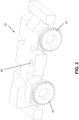
- FIG. 5 is another perspective view of the carrier unit 20 according to an embodiment.
- the carrier unit 20 may be oriented in the first coordinate system XYZ.
- the roll angle convention may be based on a right-handed positive direction of the carrier X-axis direction.
- a positive roll angle may lower the right-handed side of the crane and raise the left-handed side of the crane.
- a positive pitch angle may be based on the right-handed positive direction for the carrier Y-axis direction.
- a positive pitch angle may lower the front of the carrier unit 20 and may raise the rear of the carrier unit 20.
- the X and Z coordinates may correspond to a midplane of the telescoping boom 38.
- a lean angle may be determined to adjust the coordinates in the first coordinate system XYZ, such as the X, Z coordinates in the midplane of the telescoping boom 38.
- a unit vector near the X axis direction (“X unit vector”) based on the effect of the pitch angle may be determined.
- a unit vector near the Y axis direction (“Y unit vector”) based on the effect of the roll angle may be determined as well.
- a maximum lean angle may be determined from a Z unit vector based on the X unit vector and the Y unit vector. The maximum lean angle may then be determined based on the Z unit vector.
- the lean angle may be identified as: ⁇ L
- the maximum lean angle may then become the following: ⁇ cos ⁇ 1 Z ⁇ ′ ⁇ k ⁇ L , max
- the Z unit vector may be projected to the XY plane as a projected Z unit vector 118 (see FIG. 5 ).
- a projection 120 of the telescoping boom 38 to the XY plane may be determined based a swing (or slew) angle of the telescoping boom 38.
- the lean angle for the actual position of the telescoping boom 38 may then be determined based on the maximum lean angle, the projected Z unit vector 118 and the projected boom 120 in the XY plane.
- coordinate transformations may be used to account for the pitch and roll of the carrier unit 20 (and the crane 10).
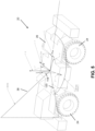
- the crane 10 may rotate about a point on the carrier unit 20, for example, at a horizontal distance h c from the Z-axis.
- the point may be shown at a vertical distance (h p2d in FIG. 6 ).
- the vertical distance may correspond to the distance from the base pivot axis 'u' of the telescoping boom 38 to the carrier deck 26.
- the telescoping boom base section 40 elevation angle may be preserved when accounting for the lean effects because a separate sensor may be used to detect the elevation angle.
- Point 'v' may be a position of the boom, and not the turntable. The base pivot axis at point 'u' would shift. Thus, adjusted coordinates may then be determined.
- a general coordinate of a point on the boom system may have X and Z coordinates.
- the coordinates may be translated to have the carrier rotation point (see FIG. 6 ) as the origin based on the general coordinate of a point on the telescoping boom system and the coordinate for the carrier rotation point.
- the coordinates may be rotated about the Y-axis based on the lean angle and the translated coordinates.
- the coordinates may then be translated back to have the origin at the original locations, i.e., where the boom base pivot axis 'u' originally was.
- the coordinates may be rotated about the Y-axis using the following (the lean angle calculated earlier may utilized):
- R ⁇ " R ⁇ ′ ⁇ cos ⁇ L 0 sin ⁇ L 0 1 0 ⁇ sin ⁇ L 0 cos ⁇ L
- coordinates of the telescoping boom 38 may be transformed in manner described above, and the transformed telescoping boom 38' is shown in broken lines, taking into account the slope information.
- the transformed operating radius is shown at R', while the original operating radius is shown at R.
- the transformed reference points u', v' and w' are shown in FIG. 6 taking into account the slope information.
- the RCL 54 may measure an operating radius from a center line of rotation of the superstructure, which may have shifted in response to a pitch and/or roll of the carrier unit 20.
- the RCL 54 may determine the operating radius during an on-rubber lifting operation in the manner described above. For example, the coordinates of different points on the crane may be adjusted to account for a pitch and/or roll of the carrier unit 20.
- FIG. 7 is a diagram showing a geometric layout of a portion of the telescoping boom 38 and the carrier unit 20 according to an embodiment.
- another approach to account for the lean during an on-rubber lifting operation may be to use a rotational coordinate system transformation for the boom pivot.
- the boom pivot 'u' remains at the origin.
- point 'w' does shift and the angle ⁇ z is altered.
- the change in angle may affect the FBD of the boom system that it may be seen to improve predicted values.
- a method 800 for monitoring a load lifted by a crane may include, at 810, determining a load lifted by a telescoping boom 38 of the crane 10, at 820, receiving pitch and/or roll information of a carrier unit 20 of the crane 10, for example, from a slope sensor 80, and at 830, adjusting coordinates of the crane 10 in a coordinate system based on the pitch and/or roll information.
- the method may further include determining a transformed operating radius R' using the adjusted coordinates, and at 850, comparing the load lifted to a rated capacity at the transformed operating radius R'.
- the RCL 54 may determine an operating radius (also referred to as a transformed operating radius R') of a crane 10, for example, during an on-rubber lift operation using pitch and/or roll information, i.e., slope information, received from the slope sensor 80.
- the transformed operating radius R' may refer to an operating radius R that has been adjusted to account for pitch and/or roll of the crane 10.
- the pitch and/or roll information may be indicative of a pitch and/or roll of the carrier unit 20.
- the pitch and/or roll information may also be indicative of a pitch and/or roll of the superstructure 30.
- the RCL 54 may transform coordinates of the crane 10 based on the pitch and/or roll information from the slope sensor 80, to account for the pitch and/or roll of the crane 10. By accounting for the pitch and/or roll of the crane 10, the RCL 54 may determine the transformed operating radius of the crane 10 during, for example, an on-rubber lift operation.
- the RCL 54 may monitor the load lifted by the crane 10 and determine the operating condition (for example a load utilization) of the crane 10 during the on-rubber lifting operation based on a comparison of the load lifted by the crane 10 to the rated capacity at the transformed operating radius R'. That is, the RCL 54 may use an operating radius determined based on the pitch and/or roll information received from the slope sensor 80 to monitor the load lifted by the crane 10 and determine the operating condition of the crane.
- the operating condition for example a load utilization
Landscapes
- Engineering & Computer Science (AREA)
- Mechanical Engineering (AREA)
- Automation & Control Theory (AREA)
- Jib Cranes (AREA)
Description
- The following description relates generally to a crane and a system and method for monitoring the crane.
- The rated capacity of a crane refers to a maximum total load the crane is designed to lift in a particular configuration. The particular configuration includes parameters which remain substantially constant during a lift operation, such as the weight of a counterweight and outrigger extension length, and parameters which may vary during the lift operation, such as an operating radius (i.e., the moment arm of the load suspended from the boom) and a swing angle (i.e., a rotational position of a boom relative to a reference point of a carrier unit of the crane in a horizontal plane). The operating radius varies with changes in boom length (for example, in response to extension or retraction of a telescoping boom) and lift angle (i.e., the angle between the boom and the horizontal plane). In general, as the operating radius increases, a load moment increases and the rated capacity decreases. Conversely, as the operating radius decreases, the load moment decreases and the rated capacity increases. To this end, load charts are provided which indicate the rated capacity at different operating radii and/or lift angles.
- A conventional crane Rated Capacity Limiter (RCL) system is configured to monitor a current load lifted by the crane and the current operating radius, for example, based on information received from one or more crane sensors and/or operator input. For example, the conventional crane RCL system may determine the current load based at least in part on information received from a pressure sensor detecting hydraulic pressure in a lift cylinder supporting the boom. The current operating radius may be determined based at least in part on information received from a sensor detecting a length of the boom and a sensor detecting the lift angle of the boom.
- The conventional crane RCL system is further configured to determine an operating condition of the crane and may control crane operations based on the operating condition. For example, the conventional crane RCL system may control the boom to prevent movement of the current load to an operating radius where the current load exceeds the rated capacity.
- A mobile crane typically includes a plurality tires for rolling contact with a support surface such that the crane may be self-propelled for transport on a road or at a worksite. The mobile crane also includes outriggers which can be deployed to engage the ground, lift the tires from the ground and support the mobile crane during a lift operation.
- As an example,
DE 10 2017 202009 A1 - It may be desirable to perform a lift operation for a relatively lightweight load without deploying the outriggers, such that the crane is supported on its tires during the lift operation. However, the crane may be susceptible to deflection in the direction of the load due to compression of the tires. Such deflection has the result of increasing the operating radius without changing a lift angle or boom length. Thus, the conventional RCL system does not detect the change in operating radius. Consequently, the conventional RCL system may compare the current load to a rated capacity in a load chart at a smaller operating radius than the current operating radius, which may affect accuracy of the comparison.
- Accordingly, it is desirable to provide a crane and a system and method for the controlling crane in which deflection of a carrier unit is accounted for when monitoring the current load and the current operating radius.
- According to the invention, a crane includes a carrier unit having a chassis, tires connected to the chassis, a carrier deck and outriggers, the outriggers movable to a deployed condition in which the outriggers engage an underlying support surface and lift the tires from the support surface such that the outriggers support the carrier unit, and a retracted condition in which the outriggers are disengaged from the support surface and the tires are engaged with the support surface, such that the tires support the carrier unit. The crane further includes a superstructure mounted on the carrier unit, the superstructure having a telescoping boom, and a slope sensor operably connected to the carrier unit and configured to detect a pitch and/or a roll of the carrier unit during a lift operation. The crane also includes a system for monitoring a load lifted by the telescoping boom. The system is configured to determine the current load lifted by the telescoping boom, receive pitch and/or roll information of the carrier unit from the slope sensor, adjust coordinates of the crane in a coordinate system based on the pitch and/or roll information, determine a transformed operating radius using the adjusted coordinates, and compare the load lifted to a rated capacity at the transformed operating radius. Additionally, the system is configured to monitor the load lifted with the outriggers in the retracted condition, and it is further configured to control vertical extension of the outriggers based on the pitch and/or roll information during movement of the outriggers to the deployed condition for leveling the carrier unit.
- According to the invention, a system is provided for monitoring a load lifted by a crane, the crane having a carrier unit and a superstructure mounted on the carrier unit, the superstructure having a telescoping boom. The system includes a processor and a non-transitory computer-readable storage medium configured to store program instructions and the processor is configured is interpret and execute the program instructions to determine a load lifted by the telescoping boom, receive slope information of the carrier unit from the slope sensor, the slope information including the detected pitch and roll of the carrier unit;control vertical extension of outriggers to level the carrier unit based on the slope information; and monitor the load lifted by the crane during an on-rubber lift operation based on the slope information, wherein to monitor the load lifted by the crane, the system is configured to:determine a current load lifted by the telescoping boom;adjust coordinates of the crane in a coordinate system based on the slope information;determine a transformed operating radius using the adjusted coordinates; and compare the current load lifted to a rated capacity at the transformed operating radius.
- According to the invention, a method is provided for monitoring a load lifted by a crane. The crane includes a carrier unit having a chassis, tires connected to the chassis, a carrier deck and outriggers, a superstructure mounted on the carrier unit, the superstructure having a telescoping boom. The crane also includes a slope sensor operably connected to the carrier unit and configured to detect a pitch and/or a roll of the carrier unit during a lift operation. The method includes determining a load lifted by the telescoping boom, receiving pitch and/or roll information of the carrier unit during a lift operation with the outriggers in the retracted condition such that the carrier unit is supported on the tires, wherein the pitch and/or roll information includes the detected pitch and/or roll of the carrier unit;adjusting coordinates of the crane in a coordinate system based on the pitch and/or roll information;determining a transformed operating radius using the adjusted coordinates; and comparing the load lifted to a rated capacity at the transformed operating radius.
- Other objects, features, and advantages of the disclosure will be apparent from the following description, taken in conjunction with the accompanying sheets of drawings, wherein like numerals refer to like parts, elements, components, steps, and processes.
-
-
FIG. 1 is a side view of a crane according to an embodiment; -
FIG. 2 is a schematic partial system diagram of the crane ofFIG. 1 according to an embodiment; -
FIG. 3 is a perspective view of a carrier unit of a crane according to an embodiment; -
FIG. 4 is a diagram showing a geometric layout of a telescoping boom according to an embodiment; -
FIG. 5 is another perspective view of a carrier unit of a crane according to an embodiment; -
FIG. 6 is a diagram showing a geometric layout of a portion of a telescoping boom and a crane carrier unit according to an embodiment; -
FIG. 7 is another diagram showing a geometric layout of a portion of a crane boom and a crane carrier according to an embodiment; and -
FIG. 8 is a block diagram showing a method for monitoring a crane according to an embodiment. - While the present disclosure is susceptible of embodiment in various forms, there is shown in the drawings and will hereinafter be described one or more embodiments with the understanding that the present disclosure is to be considered illustrative only and is not intended to limit the disclosure to any specific embodiment described or illustrated.
- Referring to
FIG. 1 , acrane 10 according to embodiments herein generally includes acarrier unit 20 and asuperstructure 30 rotatably mounted on thecarrier unit 20 and configured for rotation relative to thecarrier unit 20. Thecarrier unit 20 includes various crane components, such as achassis 22, one ormore tires 24 connected to thechassis 22, acarrier deck 26 andoutriggers 28. Thechassis 22 supports the one ormore tires 24, thecarrier deck 26 and theoutriggers 28, as well as other components such as a powertrain (not shown). The one ormore tires 24 are configured for rolling engagement with the ground, a road, or similar support surface to facilitate rolling movement of thecrane 10. For example, the powertrain may provide torque to the one ormore tires 24 to propel thecrane 10 for movement along the support surface. Thecarrier deck 26 generally defines an upwardly facing top surface of thecarrier unit 20. - The
outriggers 28 may be arranged in a deployed condition, in which theoutriggers 28 are extended horizontally outward relative to thechassis 22 to one or more extension positions, and vertically to engage an underlying support surface. Continued vertical extension of theoutriggers 28 may cause theoutriggers 28 to lift thetires 24 from the support surface, such that thecrane 10 is supported on theoutriggers 28. Theoutriggers 28 may also be arranged in a retracted condition, in which theoutriggers 28 are retracted horizontally inward toward thechassis 22 and vertically to disengage the support surface. Accordingly, in the retracted condition, thetires 24 may engage the support surface and thecrane 10 may be supported on thetires 24. In an embodiment, horizontal extension and retraction of the outriggers may be accommodated by a telescoping box and arm assembly (not shown), and vertical extension and retraction may be accommodated by a jack (not shown) operably connected to the telescoping box and arm assembly, for example, at or near a distal end of the arm. - The
superstructure 30 also includes various crane components, such as a rotatingbed 32 rotatably mounted on thecarrier unit 20, an operator'scab 34, acounterweight assembly 36 and atelescoping boom 38. The rotatingbed 32 is rotatably mounted to thecarrier unit 20 via a bearing structure and is configured to be driven in a first rotational direction, or alternatively, a second rotational direction opposite to the first rotational direction, about a generally vertical axis. The rotatingbed 32 directly or indirectly supports the operator'scab 34, thecounterweight assembly 36 and thetelescoping boom 38, as well as other crane components such as one or more hoists (not shown), such that these components are rotatable in the first and second rotational directions with the rotatingbed 32. The operator'scab 34 may include a user interface for allowing a crane operator to interact with a control system of thecrane 10 as discussed further below, for example, to control operations of one or more crane components. Thecounterweight assembly 36 includes one or more weight units supported on a frame. The weight units may be installed and removed from the frame in a desired manner to provide a selected counterweight. - The
telescoping boom 38 includes abase section 40 pivotably mounted on the rotatingbed 32 for movement through a vertically oriented range of lift angles and one ormore telescoping sections 42 configured for movement out of and into thebase section 40 generally along a boom axis to change the boom length LG. One or more hoists (not shown) are configured to wind up and pay out aflexible member 44, such as a rope or cable. A liftingappliance 46, such as a hook block, is connected to a free end of theflexible member 44 and is suspended from a free end of thetelescoping boom 38. Alift cylinder 48 is pivotably connected directly or indirectly between thebase section 40 and therotating bed 32. Thelift cylinder 48 is operable to raise or lower thetelescoping boom 38 through the range of lift angles. The rotatingbed 32 is rotatable in the first and second rotational directions to cause rotation of thetelescoping boom 38 through a range of horizontally oriented swing angles. - Referring now to
FIGS. 1 and2 , thecrane 10 further includes acontrol system 50, sometimes referred to as a Crane Control System (CCS). Thecontrol system 50 may be implemented as one or more computing devices located at thecrane 10, remote from and communicably connected to thecrane 10, or a combination thereof. Thecontrol system 50 is operably connected to various crane components (including actuators of the crane components) of thecarrier unit 20 and thesuperstructure 30 and may control operations of one or more of the crane components. For example, thecontrol system 50 may control movements of one or more crane components, including starting, stopping, preventing and allowing movements of the crane component and/or controlling a speed, acceleration and/or deceleration of the crane component. - According to an embodiment, the
control system 50 includes acrane controller 52, a rated capacity limiter (RCL) 54 and a working range limiter (WRL) 56. Thecrane controller 52 may be configured to send and/or receive control signals to various crane components to control movements of the crane components. - The
RCL 54 is a system that generally operates to monitor a current load lifted (i.e., a hook load) by thetelescoping boom 38 of thecrane 10 relative to the rated capacity of thecrane 10 at an operating radius (i.e., a hook radius). For example, theRCL 54 may determine the current load lifted and the operating radius based on information received from one or more crane sensors, user input, stored data and/or combinations thereof. TheRCL 54 may identify a rated capacity at an operating radius, for example, from a stored load chart which includes rated capacities at different operating radii or lift angle and boom length combinations. TheRCL 54 may compare the current load lifted by the crane to the rated capacity at the operating radius and control operations of one or more crane components based on the comparison. For example, theRCL 54 may control movements of the telescoping boom 38 (i.e., boom-up, boom-down, swing-left, swing-right, telescope-in and/or telescope-out movements) based on the comparison of the current load lifted to the rated capacity at the operating radius. In some embodiments, theRCL 54 may provide a control signal for controlling crane component movements directly to the crane component. In other embodiments, theRCL 54 may provide the control signal via thecontroller 52 to control movements of the crane component. - The
WRL 56 is a system that generally operates to monitor a position of a crane component relative to a position of a restricted volume. For example, theWRL 56 may determine the position of the crane component based on information received from one or more crane sensors, user input, stored data and/or combinations thereof. TheWRL 56 may identify the restricted volume, for example, based on stored position information, such as position information included in a worksite model, information received from one or more sensors (including crane sensors and/or external sensors communicably connected to the WRL 56), information received via user input and/or combinations thereof. The restricted volume may represent an obstacle, such as a building, at a worksite and define a volume in which operation of one or more crane components should be avoided. Accordingly, theWRL 56 may compare the crane component position information to the restricted volume position information and control operations of the crane component based on the comparison. For example, theWRL 56 may control movements of the telescoping boom 38 (i.e.., boom-up, boom-down, swing-left, swing-right, telescope-in and/or telescope-out movements) based on the comparison of telescoping boom position information to the restricted volume position information. In some embodiments, theWRL 56 may provide a control signal for controlling crane component movements directly to the crane component. In other embodiments, theWRL 56 may provide the control signal via thecontroller 52 to control movements of the crane component. - The
control system 50 further includescomputer components 100, such as aprocessor 58, amemory device 60, astorage device 62, acommunication device 64, aninput device 66 and/or anoutput device 68 which may be connected to one another, for example, on a bus (not shown). In an embodiment, thecomputer components 100 may be operably connected to thecontroller 52, theRCL 54 and theWRL 56. However, it will be appreciated that thecomputer components 100 may be implemented in each of thecontroller 52, theRCL 54 and theWRL 56 or distributed among thecontroller 52, theRCL 54 and theWRL 56. It will be further appreciated that although shown independently, any of thecontroller 52, theRCL 54 and theWRL 56 may be integrated with another one or more of thecontroller 52, theRCL 54 and theWRL 56 and provided as a single unit configured to perform the operations of the individual components described above. - In an embodiment, the
processor 58 may be a computer processor, such as a microprocessor, configured to interpret and execute program instructions. Theprocessor 58 is further configured to effect various operations (including movements) of one or more crane components in response to executing the program instructions. For example, theprocessor 58 may cause thecontroller 52 to provide a control signal for controlling movements of thetelescoping boom 38. It will be appreciated that the operations of thecontroller 52, theRCL 54 and theWRL 56 described herein may be carried out or otherwise effected by theprocessor 58 in response to executing program instructions. - The
memory device 60 may be a non-transitory computer-readable storage medium configured to store information, such as the program instructions to be executed by theprocessor 58. Thememory device 60 may be, for example, Random-Access Memory (RAM), Read-Only Memory (ROM) or other type of suitable memory device for storing information and/or executable program instructions. Thestorage device 62 is configured to store, for example, information, software, executable program instructions and the like which may, for example, be accessed or referenced by theprocessor 58. Thestorage device 62 may also store information collected during operation of thecrane 10, such as information received by thecontrol system 50 from one or more sensors or user input. In one embodiment, one or more load charts may be stored in thestorage device 62 and/ormemory device 60 and can be accessed or referenced, for example, by theRCL 54. Thestorage device 62 may be a non-transitory computer-readable storage medium and may include, for example, a hard disk and an associated drive and/or other similar, suitable storage devices and associated drives. - The
communication device 64 is configured to transmit and/or receive information from/to thecontrol system 50 and/or between components of thecontrol system 50. For example, thecommunication device 64 may be provided as a communication interface having a transceiver or transceiver-like component to transmitting information to, and/or receiving information from, one or more other devices, such as other communication-enabled devices, components, sensors and the like. - The
input device 66 may include, or form part of, a user interface configured to receive information from a user, such as the crane operator. Theinput device 66 may include, or be operably connected to, one or more operator controls by operation of which the user may provide information to theinput device 66. The one or more operator controls may include, for example, a lever, joystick, knob, button, dial, switch, keyboard, keypad, pointer device, touch screen display, one or more sensors such as a biometric sensor, audio sensor, light sensor and the like, including various combinations thereof. Thecontroller 52 may send a control signal to control movements of a crane component in response to information received by theinput device 66. - The
output device 68 may also include, or form part of, a user interface configured to provide information to a user, such as the crane operator. The output information may be provided visually, for example, on a display screen or with one or more lights (e.g., LEDs), audibly, for example by one or more audio speakers, and/or by way of haptic or vibratory feedback or alerts, for example, at an operator control. In some embodiments, theinput device 66 and theoutput device 68 may be provided as a single device or include components provided as a single device, for example, a display screen or touch screen display. The output information may serve as an alert or an alarm. - The crane components may be operated to conduct various movements by controlling operations of corresponding component actuators. To this end, the
control system 50 may be operably connected to one or more component actuators to control operations of the component actuators. For example, thecontrol system 50 may be operably connected tooutrigger actuators 70 for controlling movements (e.g., horizontal extension and retraction and vertical extension and retraction) of theoutriggers 28; arotating bed actuator 72 for controlling movements (e.g., rotation in the first and second rotational directions) of therotating bed 32 to cause swing-left and swing-right movements of thetelescoping boom 38 through the range of swing angles; aboom actuator 74 for controlling movements (e.g., telescope-out and telescope-in) of thetelescoping sections 42 of thetelescoping boom 38 to increase or decrease the boom length; and alift cylinder actuator 76 for controlling movements (e.g., extension and retraction) of thelift cylinder 48 to cause boom-up and boom-down movements of thetelescoping boom 38 through a range of lift angles. - Further, the
control system 50 may be operably connected to one or more crane sensors configured to provide information to thecontrol system 50 about the crane, a crane component, crane surroundings, the environment, atmospheric conditions (e.g., temperature, wind speed, and the like), and/or other information which may affect crane operations. The information may be provided as a parameter value or information from which a parameter value may be derived. In an embodiment, the crane sensors may include one ormore tire sensors 78 configured to provide tire pressure information of one ormore tires 24; one ormore slope sensors 80 configured to provide slope information (e.g., pitch information and/or roll information) of thecrane 10; one ormore outrigger sensors 82 configured to provide outrigger extension and/or pressure/load information of theoutriggers 28; one or moreswing angle sensors 84 configured to provide swing angle information of therotating bed 32 and/or thetelescoping boom 38; one or moreboom length sensors 86 configured to provide boom length information of thetelescoping boom 38; one morelift angle sensors 88 configured to provide lift angle information of thetelescoping boom 38; and one or more liftcylinder pressure sensors 90 configured to provide lift cylinder pressure information of thelift cylinder 48. Other sensors may be implemented as well, for example, a lift cylinder angle sensor for providing lift cylinder angle information to thecontrol system 50, and/or additional flow, pressure, load, proximity sensors and the like. It will be appreciated that althoughFIG. 2 shows various crane sensors associated with particular crane components, the crane sensors may be mounted or positioned with different crane components suitable for providing the intended information described herein. - Referring now to
FIGS. 2 and3 , theRCL 54 may determine a current load lifted by thecrane 10. In an embodiment, theRCL 54 may determine the load lifted by thecrane 10 based, at least in part, on information received from one or more crane sensors. For example, the RCL may receive lift cylinder pressure information from the one or more liftcylinder pressure sensors 90 and determine the load lifted by thecrane 10 based on the lift cylinder pressure information. In one embodiment, theRCL 54 may calculate the current load lifted based on a formulaic relationship between the lift cylinder pressure and the current load lifted. Alternatively, or in addition, theRCL 54 may retrieve the current load lifted from thememory device 60 orstorage device 62 based on known load values corresponding to different lift cylinder pressures or based on user input information, for example, when the load is known. - The
RCL 54 may also determine an operating radius of the current load lifted by thecrane 10 based, at least in part, on information received from one or more crane sensors. For example, theRCL 54 may receive lift angle information from one or morelift angle sensors 88 and boom length information from one or moreboom length sensors 86 and determine the operating radius based on the lift angle information and the boom length information. In one embodiment, theRCL 54 may calculate the operating radius based on formulaic relationship between the lift angle, boom length and operating radius. Alternatively, or in addition, theRCL 54 may retrieve the operating radius from thememory device 60 orstorage device 62 based on known operating radii values corresponding to different lift angles and boom lengths. - The operating radius of the load lifted by the
crane 10 may further be determined based on a pitch and/or roll of thecrane 10. The pitch of thecrane 10 generally refers to rotation of the carrier unit 20 (e.g.,chassis 22, carrier deck 26) and/or rotatingbed 32 about an axis extending laterally across thecrane 10. Thus, the pitch of thecrane 10 results in an upward or downward deflection of a front end or a rear end of thecarrier deck 26. The roll of thecrane 10 generally refers to rotation of the carrier unit 20 (e.g.,chassis 22, the carrier deck 26) and/or therotating bed 32 about an axis extending longitudinally along thecrane 10. Thus, the roll of thecrane 10 results in an upward or downward deflection of the left or right lateral sides of thecarrier deck 26. TheRCL 54 may receive pitch information and roll information (referred to collectively as "slope information") from one or more crane sensors. For example, theRCL 54 may receive information regarding deflection of thecarrier unit 20 at different locations from one or more crane sensors and may then calculate slope information based on information regarding deflection of thecarrier unit 20. - The control system 50 (including the RCL 54) may receive slope information from one or
more slope sensors 80, mounted on thecarrier unit 20, for example, thechassis 22 orcarrier deck 26, or on thesuperstructure 30, for example, on therotating bed 32. During movement of theoutriggers 28 to the deployed condition, such that thetires 24 are lifted from the support surface and thecrane 10 is supported on theoutriggers 28, theslope sensor 80 may provide pitch and roll information to thecontrol system 50 to allow for leveling ofcarrier unit 20, for example, thecarrier deck 26. For example, thecontrol system 50 may control vertical extension of one ormore outriggers 28 to effect a change in pitch and/or roll of thecarrier deck 26 until thecarrier deck 26 is substantially level. Thecrane 10 may perform a lift operation with theoutriggers 28 deployed. During such a lift operation, pitch and/or roll of thecarrier deck 26 is expected to be relatively small and may not substantially affect the operating radius. - However, in some scenarios, it may be beneficial or permissible to perform a lift operation with the
outriggers 28 in the retracted condition, such that thecrane 10 is supported on thetires 24. Such a lift operation is commonly referred to as an "on-rubber" lift operation. Generally, during an on-rubber lift operation, thecarrier deck 26 is expected to pitch and/or roll to a greater extent than during a lift operation performed with deployedoutriggers 28, due to deformation of thetires 24. Pitch and/or roll of thecrane 10 during the on-rubber lift operation may cause an increase in operating radius, and consequently, may cause a decrease in the rated capacity (i.e., maximum permissible load at an operating radius). - According to embodiments herein, the
RCL 54 is configured to determine an operating radius further based, at least in part, on the slope information (i.e., pitch information and/or roll information). In one embodiment, the slope information may be received by theRCL 54 from theslope sensor 80. TheRCL 54 may monitor the current load lifted at the operating radius determined based at least in part on the slope information. For example, theRCL 54 may compare the current load lifted to a rated capacity of the of thecrane 10 at the operating radius determined based at least in part on the slope information. Further still, theRCL 54 may control operations of one or more crane components, such as thetelescoping boom 38, based on the comparison of the current load lifted to the rated capacity at the operating radius determined based at least in part on the slope information. For example, theRCL 54 may reduce or limit a speed, and/or prevent or limit movement of thetelescoping boom 38 in a direction which may cause the rated capacity to approach the current load lifted, within a predetermined threshold. - With reference to
FIGS. 4 and5 , theRCL 54 is configured to provide a coordinate system XYZ for thecarrier unit 20. TheRCL 54 may determine coordinates for a plurality of points in the coordinate system XYZ. For example, theRCL 54 may determine X and Z coordinates for three points u, v, w in the coordinate system XYZ which may correspond to predetermined points on thecrane 10 as shown inFIG. 4 . For example, point 'u' may correspond to a base pivot axis of thetelescoping boom 38 and may serve as an origin for the coordinate system XYZ. Points 'v' and 'w' may also correspond to points in a geometric layout of thetelescoping boom 38. For example, point 'v' may correspond to a pivot axis formed by a connection of thelift cylinder 48 to thebase section 40 of theboom 38, and point 'w' may correspond to a base pivot axis of thelift cylinder 48. - Referring to
FIGS. 4 and6 , theRCL 54 may transform the coordinates based on the slope information. For example, theRCL 54 may determine a lean angle of thecrane 10, such as a lean angle of thecarrier unit 20, based on the slope information. In an embodiment, the lean angle may be determined based on a pitch angle and a roll angle, which may be determined based on the slope information. The coordinates may be adjusted using the lean angle. A lean angle for the actual position of thetelescoping boom 28 may be determined as well. With a known lean angle, the coordinate transformations may account for the pitch and the roll of thecrane 10 about a point on thecarrier unit 20. - General coordinates of points located on the
telescoping boom 38, or related components (e.g., the lift cylinder 48) may be translated to have thecarrier unit 20 rotation point (i.e., the point on thecarrier unit 20 about which thecarrier unit 20 pitches and/or rolls) as the origin of the coordinate system. The coordinates may be rotated about the Y-axis using the lean angle. The coordinates may then be translated back to have the origin at the original location, i.e., at the base pivot axis (point 'u') of thetelescoping boom 38. Such operations may be performed by theRCL 54. - Alternatively, with reference to
FIG. 7 , theRCL 54 may transform the coordinates of the of the points using a rotational coordinate system transformation for the base pivot axis (at point 'u') of thetelescoping boom 38. Thus, the base pivot axis of thetelescoping boom 38 may remain at the origin of the coordinate system. However, the reference point 'w' does shift and the lift cylinder angle is altered. - Accordingly, in the embodiments above, the
RCL 54 may determine an adjusted, or transformed operating radius based on the slope information, such that the transformed operating radius takes into account a pitch and/or roll of thecrane 10, for example, during an on-rubber lift operation. - The
RCL 54 may additionally be configured to store, for example, crane geometry information, crane weight information, or both, and may use such information to determine the transformed operating radius. For example, the crane geometry information may be used by theRCL 54 to create a geometric model of thecrane 10 or a crane component, such as thetelescoping boom 38. The crane geometry information may include, for example, various dimensions, distances between components, coordinate system information, coordinate information of reference points and/or crane components, and the like. The crane geometry information may be provided, for example, based on sensor information and/or user input. Weight information may include, for example, a weight profile of thecrane 10, a weight of the load lifted by the crane, weights of various crane components and the like. - Referring again to
FIG. 4 , a geometric layout of thetelescoping boom 38 in XZ plane of an XYZ coordinate system includes the reference points 'u', 'v' and 'w.' In addition, thetelescoping sections 42 are shown each having a first end A1, A2...Ai at a proximal end and a second end B2, B3...Bi+1 at a distal end. A length L1, L2...Li of eachtelescoping section 42 is the distance between the second end B2, B3...Bi+1 and the first end A1, A2...Ai of therespective telescoping sections 42. Thebase section 40 is shown having a second end B1 at a distal end and having a length L0. In addition, a length of thebase section 40 to the pivot connection axis at reference point 'v' is shown as Lz. A length of thetelescoping boom 38 is shown as LG. A lift angle of thetelescoping boom 38 is shown as β 0. A lift cylinder angle is shown as αZ . - Accordingly, with further reference to
FIG. 4 , the following coordinates may be determined:
Xu : Horizontal (x-axis) position of the reference point 'u';
- Xw : Horizontal (x-axis) position of the reference point 'w'; and
- hB : Horizontal distance between the reference point 'u' and the reference point 'w'; and

- Xv : Horizontal (x-axis) position reference point 'v';
- Lz : Length of the
base section 40 from the origin to the reference point 'v'; - β 0: Lift angle of the
telescoping boom 38; - ez : Perpendicular distance between reference point 'v' and the
base section 40 of thetelescoping boom 38; and - ef : Perpendicular distance between the
base section 40 thetelescoping boom 38 and the reference point 'u'.
- Still referring to
FIG. 4 , the following 'Z' coordinates are determined:
Zu : Vertical (Z-axis) position of the reference point 'u';
- Zw : Vertical (Z-axis) position of the reference point 'w'; and
- hA : Vertical distance between the reference point 'u' and the reference point 'w'; and

Zv : Vertical (Z-axis) position of the reference point 'v'; - According to an embodiment, the lift cylinder angle αZ may be determined as:
- If Xv > Xw:

- If Xw > Xv:

-
FIG. 5 is another perspective view of thecarrier unit 20 according to an embodiment. InFIG. 5 , thecarrier unit 20 may be oriented in the first coordinate system XYZ. In an embodiment, the roll angle convention may be based on a right-handed positive direction of the carrier X-axis direction. A positive roll angle may lower the right-handed side of the crane and raise the left-handed side of the crane. A positive pitch angle may be based on the right-handed positive direction for the carrier Y-axis direction. A positive pitch angle may lower the front of thecarrier unit 20 and may raise the rear of thecarrier unit 20. The X and Z coordinates may correspond to a midplane of thetelescoping boom 38. - A lean angle may be determined to adjust the coordinates in the first coordinate system XYZ, such as the X, Z coordinates in the midplane of the
telescoping boom 38. A unit vector near the X axis direction ("X unit vector") based on the effect of the pitch angle may be determined. A unit vector near the Y axis direction ("Y unit vector") based on the effect of the roll angle may be determined as well. A maximum lean angle may be determined from a Z unit vector based on the X unit vector and the Y unit vector. The maximum lean angle may then be determined based on the Z unit vector. - The lean angle may be identified as:
ωL - The X unit vector may be identified as:

ωP : Pitch angle - The Y unit vector may be identified as:

ωR : Roll angle - The maximum lean angle may be determined from the following vector:

- The maximum lean angle may then become the following:

- The Z unit vector may be projected to the XY plane as a projected Z unit vector 118 (see
FIG. 5 ). Aprojection 120 of thetelescoping boom 38 to the XY plane may be determined based a swing (or slew) angle of thetelescoping boom 38. The lean angle for the actual position of thetelescoping boom 38 may then be determined based on the maximum lean angle, the projectedZ unit vector 118 and the projectedboom 120 in the XY plane. - The
projection 118 of the Z unit vector to the XY plane may be determined as follows:
- The
projection 120 of thetelescoping boom 38 to the XY plane may be determined as follows:
α: Swing angle - The lean angle for the actual position of the
telescoping boom 38 may then become the following:
- Referring now to
FIG. 6 , with the lean angle known, coordinate transformations may be used to account for the pitch and roll of the carrier unit 20 (and the crane 10). Thecrane 10 may rotate about a point on thecarrier unit 20, for example, at a horizontal distance hc from the Z-axis. The point may be shown at a vertical distance (hp2d inFIG. 6 ). In one embodiment, the vertical distance may correspond to the distance from the base pivot axis 'u' of thetelescoping boom 38 to thecarrier deck 26. The telescopingboom base section 40 elevation angle may be preserved when accounting for the lean effects because a separate sensor may be used to detect the elevation angle. Point 'v' may be a position of the boom, and not the turntable. The base pivot axis at point 'u' would shift. Thus, adjusted coordinates may then be determined. - The coordinates may be adjusted as follows:


- In an embodiment, a general coordinate of a point on the boom system may have X and Z coordinates. The coordinates may be translated to have the carrier rotation point (see
FIG. 6 ) as the origin based on the general coordinate of a point on the telescoping boom system and the coordinate for the carrier rotation point. The coordinates may be rotated about the Y-axis based on the lean angle and the translated coordinates. The coordinates may then be translated back to have the origin at the original locations, i.e., where the boom base pivot axis 'u' originally was. - The following may indicate the general coordinate of a point on the boom system:

- The coordinates may be translated to have the carrier rotation point as the origin, in the following manner:


- The coordinates may be rotated about the Y-axis using the following (the lean angle calculated earlier may utilized):

- The coordinates may be translated back to have the origin at the original locations (where the boom pivot originally was) as follows:

- With further reference to
FIG. 6 , coordinates of thetelescoping boom 38 may be transformed in manner described above, and the transformed telescoping boom 38' is shown in broken lines, taking into account the slope information. In addition, the transformed operating radius is shown at R', while the original operating radius is shown at R. The transformed reference points u', v' and w' are shown inFIG. 6 taking into account the slope information. In an on-rubber lifting operation, theRCL 54 may measure an operating radius from a center line of rotation of the superstructure, which may have shifted in response to a pitch and/or roll of thecarrier unit 20. TheRCL 54 may determine the operating radius during an on-rubber lifting operation in the manner described above. For example, the coordinates of different points on the crane may be adjusted to account for a pitch and/or roll of thecarrier unit 20. -
FIG. 7 is a diagram showing a geometric layout of a portion of thetelescoping boom 38 and thecarrier unit 20 according to an embodiment. With reference toFIG. 7 , another approach to account for the lean during an on-rubber lifting operation may be to use a rotational coordinate system transformation for the boom pivot. In such an approach, the boom pivot 'u' remains at the origin. However, point 'w' does shift and the angle αz is altered. The change in angle may affect the FBD of the boom system that it may be seen to improve predicted values. - Referring to
FIG. 8 , according to an embodiment, amethod 800 for monitoring a load lifted by a crane may include, at 810, determining a load lifted by atelescoping boom 38 of thecrane 10, at 820, receiving pitch and/or roll information of acarrier unit 20 of thecrane 10, for example, from aslope sensor 80, and at 830, adjusting coordinates of thecrane 10 in a coordinate system based on the pitch and/or roll information. At 840, the method may further include determining a transformed operating radius R' using the adjusted coordinates, and at 850, comparing the load lifted to a rated capacity at the transformed operating radius R'. - Accordingly, in the embodiments above, the
RCL 54 may determine an operating radius (also referred to as a transformed operating radius R') of acrane 10, for example, during an on-rubber lift operation using pitch and/or roll information, i.e., slope information, received from theslope sensor 80. In one embodiment, the transformed operating radius R' may refer to an operating radius R that has been adjusted to account for pitch and/or roll of thecrane 10. The pitch and/or roll information may be indicative of a pitch and/or roll of thecarrier unit 20. The pitch and/or roll information may also be indicative of a pitch and/or roll of thesuperstructure 30. - The
RCL 54 may transform coordinates of thecrane 10 based on the pitch and/or roll information from theslope sensor 80, to account for the pitch and/or roll of thecrane 10. By accounting for the pitch and/or roll of thecrane 10, theRCL 54 may determine the transformed operating radius of thecrane 10 during, for example, an on-rubber lift operation. - In the manner above, the
RCL 54 may monitor the load lifted by thecrane 10 and determine the operating condition (for example a load utilization) of thecrane 10 during the on-rubber lifting operation based on a comparison of the load lifted by thecrane 10 to the rated capacity at the transformed operating radius R'. That is, theRCL 54 may use an operating radius determined based on the pitch and/or roll information received from theslope sensor 80 to monitor the load lifted by thecrane 10 and determine the operating condition of the crane. - It is understood that the relative directions described above, e.g, "upward," "downward," "upper," "lower," "above," "below," are used for illustrative purposes only and may change depending on an orientation of a particular component. Accordingly, this terminology is non-limiting in nature. In addition, it is understood that one or more various features of an embodiment above may be used in, combined with, or replace other features of a different embodiment described herein.
- In the present disclosure, the words "a" or "an" are to be taken to include both the singular and the plural. Conversely, any reference to plural items shall, where appropriate, include the singular.
- From the foregoing it will be observed that numerous modifications and variations can be effectuated without departing from the true spirit and scope of the novel concepts of the present invention. It is to be understood that no limitation with respect to the specific embodiments illustrated is intended or should be inferred. The disclosure is intended to cover by the appended claims all such modifications as fall within the scope of the claims.
Claims (7)
- A crane (10) comprising:a carrier unit (20) having a chassis (22), tires (24) connected to the chassis (22), a carrier deck (26) and outriggers (28), the outriggers (28) movable to a deployed condition in which the outriggers (28) engage an underlying support surface and lift the tires (24) from the support surface such that the outriggers (28) support the carrier unit (20), and a retracted condition in which the outriggers (28) are disengaged from the support surface and the tires (24) are engaged with the support surface, such that the tires (24) support the carrier unit (20);a superstructure (30) mounted on the carrier unit (20), the superstructure (30) comprising a telescoping boom (38);a slope sensor (80) operably connected to the carrier unit (20) and configured to detect a pitch and/or a roll of the carrier unit (20) during a lift operation; anda system (50) for monitoring a load lifted by the telescoping boom (38), the system (50) configured to:determine the current load lifted by the telescoping boom (38);receive pitch and/or roll information of the carrier unit (20) from the slope sensor (80);adjust coordinates of the crane (10) in a coordinate system based on the pitch and/or roll information;determine a transformed operating radius (R') using the adjusted coordinates; andcompare the current load lifted to a rated capacity at the transformed operating radius (R'),characterized in that the system (50) is configured to monitor the load lifted with the outriggers (28) in the retracted condition, andwherein the system (50) is further configured to control vertical extension of the outriggers (28) based on the pitch and/or roll information during movement of the outriggers (28) to the deployed condition for leveling the carrier unit (20).
- The crane of claim 1, wherein the system (50) is configured to control one or more movements of the telescoping boom (38) based on the comparison of the current load lifted to the rated capacity at the transformed operating radius (R').
- The crane of claim 1, wherein the system (50) is configured to receive boom length information from a boom length sensor (86) and lift angle information from a lift angle sensor (88).
- The crane of claim 1, wherein the system (50) stores one or more load charts and the rated capacity at the transformed operating radius (R') is determined from a load chart of the one or more load charts.
- A system (50) for monitoring a load lifted by a crane (10), the crane (10) comprising a carrier unit (20), a slope sensor (80) mounted on the carrier unit (20) configured to detect a pitch and a roll of the carrier unit (20), and a superstructure (30) mounted on the carrier unit (20), the superstructure (30) comprising a telescoping boom (38), the system (50) comprising:
a processor (58) and a non-transitory computer-readable storage medium (60) configured to store program instructions and the processor is configured is interpret and execute the program instructions to:receive slope information of the carrier unit from the slope sensor (80), the slope information including the detected pitch and roll of the carrier unit (20);control vertical extension of outriggers (28) to level the carrier unit (20) based on the slope information; andmonitor the load lifted by the crane (10) during an on-rubber lift operation based on the slope information, wherein to monitor the load lifted by the crane (10), the system (50) is configured to:determine a current load lifted by the telescoping boom (38);adjust coordinates of the crane (10) in a coordinate system based on the slope information;determine a transformed operating radius (R') using the adjusted coordinates; andcompare the current load lifted to a rated capacity at the transformed operating radius (R'). - The system of claim 5, further configured to control movements of the telescoping boom (38) based on the comparison of the load lifted to the rated capacity at the transformed operating radius (R').
- A method for monitoring a load lifted by a crane (10), the crane (10) comprising a carrier unit (20) having a chassis (22), tires (24) connected to the chassis (22), a carrier deck (26) and outriggers (28), the outriggers (28) movable between retracted and deployed conditions, a superstructure (30) mounted on the carrier unit (20), the superstructure (30) comprising a telescoping boom (38), and a slope sensor (80) operably connected to the carrier unit (20) and configured to detect a pitch and/or a roll of the carrier unit (20) during a lift operation, the method comprising:determining a load lifted by the telescoping boom (38);receiving pitch and/or roll information of the carrier unit during a lift operation with the outriggers (28) in the retracted condition such that the carrier unit (20) is supported on the tires (24), wherein the pitch and/or roll information includes the detected pitch and/or roll of the carrier unit (20);adjusting coordinates of the crane (10) in a coordinate system based on the pitch and/or roll information;determining a transformed operating radius (R') using the adjusted coordinates; andcomparing the load lifted to a rated capacity at the transformed operating radius (R').
Applications Claiming Priority (3)
| Application Number | Priority Date | Filing Date | Title |
|---|---|---|---|
| US201962948799P | 2019-12-16 | 2019-12-16 | |
| US201962948795P | 2019-12-16 | 2019-12-16 | |
| PCT/US2020/065438 WO2021127058A1 (en) | 2019-12-16 | 2020-12-16 | System and method for monitoring crane and crane having the same |
Publications (2)
| Publication Number | Publication Date |
|---|---|
| EP4077198A1 EP4077198A1 (en) | 2022-10-26 |
| EP4077198B1 true EP4077198B1 (en) | 2025-02-05 |
Family
ID=74186872
Family Applications (1)
| Application Number | Title | Priority Date | Filing Date |
|---|---|---|---|
| EP20842410.1A Active EP4077198B1 (en) | 2019-12-16 | 2020-12-16 | System and method for monitoring crane and crane having the same |
Country Status (5)
| Country | Link |
|---|---|
| US (1) | US11713222B2 (en) |
| EP (1) | EP4077198B1 (en) |
| JP (1) | JP7695938B2 (en) |
| CN (1) | CN115052830B (en) |
| WO (1) | WO2021127058A1 (en) |
Families Citing this family (4)
| Publication number | Priority date | Publication date | Assignee | Title |
|---|---|---|---|---|
| US20220194765A1 (en) * | 2020-12-17 | 2022-06-23 | Xtreme Manufacturing, Llc | Systems and methods for use in coordinating boom motion of a construction machine |
| WO2023022205A1 (en) * | 2021-08-19 | 2023-02-23 | 株式会社タダノ | Loading type truck crane |
| US11891278B1 (en) | 2022-08-31 | 2024-02-06 | Caterpillar Inc. | Lifting capacity systems and methods for lifting machines |
| CN116902835A (en) * | 2023-06-30 | 2023-10-20 | 湖南三一中型起重机械有限公司 | Landing leg leveling method, landing leg leveling device, landing leg leveling system and vehicle |
Citations (1)
| Publication number | Priority date | Publication date | Assignee | Title |
|---|---|---|---|---|
| EP3670422A1 (en) * | 2018-12-21 | 2020-06-24 | Sumitomo Heavy Industries Construction Cranes Co., Ltd. | Mobile crane |
Family Cites Families (16)
| Publication number | Priority date | Publication date | Assignee | Title |
|---|---|---|---|---|
| GB1183190A (en) * | 1967-08-15 | 1970-03-04 | B & A Engineering Company Ltd | Crane Radius Indicator or Crane Safe-Load Indicator Radius Compensating Device |
| GB1360128A (en) * | 1972-05-16 | 1974-07-17 | Pye Ltd | Crane load indicating arrangement |
| JPH0751438B2 (en) * | 1990-08-20 | 1995-06-05 | 株式会社神戸製鋼所 | Tilt angle calculator for upper revolving structure in construction machinery |
| US5251768A (en) | 1990-03-23 | 1993-10-12 | Kabushiki Kaisha Kobe Seiko Sho | Method and device for controlling braking of an upper rotary body of a construction machine and a device for calculating the inclination angle of the upper rotary body |
| CN2073869U (en) * | 1990-06-11 | 1991-03-27 | 宜昌市葛洲坝智能电器厂 | Omnibearing protector of loading moment for use in engineering hoister |
| JPH07125987A (en) * | 1993-11-08 | 1995-05-16 | Komatsu Mec Corp | Lifting load and tipping moment detection device for mobile cranes |
| JPH1017273A (en) * | 1996-07-02 | 1998-01-20 | Komatsu Ltd | Crane stop control device |
| CN102395480B (en) | 2009-04-17 | 2014-06-11 | 沃尔沃建筑设备公司 | Vehicle and method for operating the vehicle |
| US8272521B1 (en) * | 2009-10-05 | 2012-09-25 | Auto Crane Company | Crane moment load and load delivery system control and method |
| US9284167B2 (en) | 2009-11-11 | 2016-03-15 | Flanders Electric Motor Service, Inc. | Dynamic jack reference control system and method for extending vehicle jacks |
| CN102464270B (en) * | 2010-11-11 | 2014-05-14 | 徐州重型机械有限公司 | Overturning-preventing torque limiter and movable crane |
| AU2014231780A1 (en) * | 2013-03-15 | 2015-09-24 | Terex Australia Pty Ltd | Crane load rating system |
| JP6147062B2 (en) * | 2013-04-02 | 2017-06-14 | 株式会社タダノ | Work condition check device for work equipment |
| DE202015001023U1 (en) * | 2015-02-09 | 2016-05-10 | Liebherr-Components Biberach Gmbh | crane |
| DE102017202009A1 (en) * | 2016-03-21 | 2017-09-21 | Tadano Faun Gmbh | crane |
| CA3012498A1 (en) * | 2017-07-28 | 2019-01-28 | Brandt Equipment Solutions Ltd. | Monitoring system and method |
-
2020
- 2020-12-16 WO PCT/US2020/065438 patent/WO2021127058A1/en not_active Ceased
- 2020-12-16 US US17/124,471 patent/US11713222B2/en active Active
- 2020-12-16 EP EP20842410.1A patent/EP4077198B1/en active Active
- 2020-12-16 CN CN202080096592.5A patent/CN115052830B/en active Active
- 2020-12-16 JP JP2022536785A patent/JP7695938B2/en active Active
Patent Citations (1)
| Publication number | Priority date | Publication date | Assignee | Title |
|---|---|---|---|---|
| EP3670422A1 (en) * | 2018-12-21 | 2020-06-24 | Sumitomo Heavy Industries Construction Cranes Co., Ltd. | Mobile crane |
Also Published As
| Publication number | Publication date |
|---|---|
| US11713222B2 (en) | 2023-08-01 |
| CN115052830A (en) | 2022-09-13 |
| US20210179396A1 (en) | 2021-06-17 |
| WO2021127058A1 (en) | 2021-06-24 |
| EP4077198A1 (en) | 2022-10-26 |
| JP7695938B2 (en) | 2025-06-19 |
| CN115052830B (en) | 2025-09-09 |
| JP2023506507A (en) | 2023-02-16 |
Similar Documents
| Publication | Publication Date | Title |
|---|---|---|
| US11713222B2 (en) | System and method for monitoring crane and crane having same | |
| US11293169B2 (en) | Wheel loader and bucket load calculation method | |
| JP6177400B1 (en) | Crane truck | |
| US4752012A (en) | Crane control means employing load sensing devices | |
| US9783397B2 (en) | Work state monitoring device for work vehicle | |
| US8272521B1 (en) | Crane moment load and load delivery system control and method | |
| US20170334687A1 (en) | Crane and method for monitoring the overload protection of such a crane | |
| US20140320293A1 (en) | Operator alert and height limitation system for load carrying machines | |
| EP3636582B1 (en) | A machine, controller, and control method | |
| WO2020085314A1 (en) | Crane device, method for determining number of falls, and program | |
| JPWO2020166721A1 (en) | Ground cutting control device and crane | |
| US20210139297A1 (en) | Height adjustment assistance device, crane comprising same, and height adjustment method | |
| EP4036045A1 (en) | Control system and work machine | |
| EP3925919B1 (en) | Lifting control device and mobile crane | |
| CN113382947B (en) | Ground-off determination device, ground-off control device, mobile crane, and ground-off determination method | |
| WO2021246491A1 (en) | Dynamic lift-off control device, and crane | |
| US12623890B2 (en) | Loading type truck crane | |
| JP2002046998A (en) | Body tilt angle detection device for boom work vehicles | |
| US20170121931A1 (en) | Control System for Mining Machine | |
| JP7435090B2 (en) | Boom tip position prediction system | |
| EP3763664B1 (en) | Method for operating a crane, crane operation system and crane comprising it | |
| KR20210155459A (en) | excavator for roll-over preventing and method using the same | |
| JP2873498B2 (en) | Boom-type work vehicle safety device | |
| JP7000917B2 (en) | Mobile crane and its slinging tool length estimation method | |
| JP3117791B2 (en) | Crane hoisting stop control device |
Legal Events
| Date | Code | Title | Description |
|---|---|---|---|
| STAA | Information on the status of an ep patent application or granted ep patent |
Free format text: STATUS: UNKNOWN |
|
| STAA | Information on the status of an ep patent application or granted ep patent |
Free format text: STATUS: THE INTERNATIONAL PUBLICATION HAS BEEN MADE |
|
| PUAI | Public reference made under article 153(3) epc to a published international application that has entered the european phase |
Free format text: ORIGINAL CODE: 0009012 |
|
| STAA | Information on the status of an ep patent application or granted ep patent |
Free format text: STATUS: REQUEST FOR EXAMINATION WAS MADE |
|
| 17P | Request for examination filed |
Effective date: 20220630 |
|
| AK | Designated contracting states |
Kind code of ref document: A1 Designated state(s): AL AT BE BG CH CY CZ DE DK EE ES FI FR GB GR HR HU IE IS IT LI LT LU LV MC MK MT NL NO PL PT RO RS SE SI SK SM TR |
|
| DAV | Request for validation of the european patent (deleted) | ||
| DAX | Request for extension of the european patent (deleted) | ||
| GRAP | Despatch of communication of intention to grant a patent |
Free format text: ORIGINAL CODE: EPIDOSNIGR1 |
|
| STAA | Information on the status of an ep patent application or granted ep patent |
Free format text: STATUS: GRANT OF PATENT IS INTENDED |
|
| INTG | Intention to grant announced |
Effective date: 20240730 |
|
| GRAS | Grant fee paid |
Free format text: ORIGINAL CODE: EPIDOSNIGR3 |
|
| P01 | Opt-out of the competence of the unified patent court (upc) registered |
Free format text: CASE NUMBER: APP_61365/2024 Effective date: 20241115 |
|
| GRAA | (expected) grant |
Free format text: ORIGINAL CODE: 0009210 |
|
| STAA | Information on the status of an ep patent application or granted ep patent |
Free format text: STATUS: THE PATENT HAS BEEN GRANTED |
|
| AK | Designated contracting states |
Kind code of ref document: B1 Designated state(s): AL AT BE BG CH CY CZ DE DK EE ES FI FR GB GR HR HU IE IS IT LI LT LU LV MC MK MT NL NO PL PT RO RS SE SI SK SM TR |
|
| REG | Reference to a national code |
Ref country code: GB Ref legal event code: FG4D |
|
| REG | Reference to a national code |
Ref country code: CH Ref legal event code: EP |
|
| REG | Reference to a national code |
Ref country code: DE Ref legal event code: R096 Ref document number: 602020045753 Country of ref document: DE |
|
| REG | Reference to a national code |
Ref country code: IE Ref legal event code: FG4D |
|
| REG | Reference to a national code |
Ref country code: NL Ref legal event code: MP Effective date: 20250205 |
|
| PG25 | Lapsed in a contracting state [announced via postgrant information from national office to epo] |
Ref country code: RS Free format text: LAPSE BECAUSE OF FAILURE TO SUBMIT A TRANSLATION OF THE DESCRIPTION OR TO PAY THE FEE WITHIN THE PRESCRIBED TIME-LIMIT Effective date: 20250505 |
|
| PG25 | Lapsed in a contracting state [announced via postgrant information from national office to epo] |
Ref country code: FI Free format text: LAPSE BECAUSE OF FAILURE TO SUBMIT A TRANSLATION OF THE DESCRIPTION OR TO PAY THE FEE WITHIN THE PRESCRIBED TIME-LIMIT Effective date: 20250205 |
|
| PG25 | Lapsed in a contracting state [announced via postgrant information from national office to epo] |
Ref country code: PL Free format text: LAPSE BECAUSE OF FAILURE TO SUBMIT A TRANSLATION OF THE DESCRIPTION OR TO PAY THE FEE WITHIN THE PRESCRIBED TIME-LIMIT Effective date: 20250205 |
|
| PG25 | Lapsed in a contracting state [announced via postgrant information from national office to epo] |
Ref country code: ES Free format text: LAPSE BECAUSE OF FAILURE TO SUBMIT A TRANSLATION OF THE DESCRIPTION OR TO PAY THE FEE WITHIN THE PRESCRIBED TIME-LIMIT Effective date: 20250205 |
|
| REG | Reference to a national code |
Ref country code: LT Ref legal event code: MG9D |
|
| PG25 | Lapsed in a contracting state [announced via postgrant information from national office to epo] |
Ref country code: IS Free format text: LAPSE BECAUSE OF FAILURE TO SUBMIT A TRANSLATION OF THE DESCRIPTION OR TO PAY THE FEE WITHIN THE PRESCRIBED TIME-LIMIT Effective date: 20250605 Ref country code: NO Free format text: LAPSE BECAUSE OF FAILURE TO SUBMIT A TRANSLATION OF THE DESCRIPTION OR TO PAY THE FEE WITHIN THE PRESCRIBED TIME-LIMIT Effective date: 20250505 |
|
| PG25 | Lapsed in a contracting state [announced via postgrant information from national office to epo] |
Ref country code: NL Free format text: LAPSE BECAUSE OF FAILURE TO SUBMIT A TRANSLATION OF THE DESCRIPTION OR TO PAY THE FEE WITHIN THE PRESCRIBED TIME-LIMIT Effective date: 20250205 |
|
| PG25 | Lapsed in a contracting state [announced via postgrant information from national office to epo] |
Ref country code: HR Free format text: LAPSE BECAUSE OF FAILURE TO SUBMIT A TRANSLATION OF THE DESCRIPTION OR TO PAY THE FEE WITHIN THE PRESCRIBED TIME-LIMIT Effective date: 20250205 |
|
| PG25 | Lapsed in a contracting state [announced via postgrant information from national office to epo] |
Ref country code: LV Free format text: LAPSE BECAUSE OF FAILURE TO SUBMIT A TRANSLATION OF THE DESCRIPTION OR TO PAY THE FEE WITHIN THE PRESCRIBED TIME-LIMIT Effective date: 20250205 Ref country code: PT Free format text: LAPSE BECAUSE OF FAILURE TO SUBMIT A TRANSLATION OF THE DESCRIPTION OR TO PAY THE FEE WITHIN THE PRESCRIBED TIME-LIMIT Effective date: 20250605 |
|
| PG25 | Lapsed in a contracting state [announced via postgrant information from national office to epo] |
Ref country code: GR Free format text: LAPSE BECAUSE OF FAILURE TO SUBMIT A TRANSLATION OF THE DESCRIPTION OR TO PAY THE FEE WITHIN THE PRESCRIBED TIME-LIMIT Effective date: 20250506 Ref country code: BG Free format text: LAPSE BECAUSE OF FAILURE TO SUBMIT A TRANSLATION OF THE DESCRIPTION OR TO PAY THE FEE WITHIN THE PRESCRIBED TIME-LIMIT Effective date: 20250205 |
|
| REG | Reference to a national code |
Ref country code: AT Ref legal event code: MK05 Ref document number: 1764866 Country of ref document: AT Kind code of ref document: T Effective date: 20250205 |
|
| PG25 | Lapsed in a contracting state [announced via postgrant information from national office to epo] |
Ref country code: SE Free format text: LAPSE BECAUSE OF FAILURE TO SUBMIT A TRANSLATION OF THE DESCRIPTION OR TO PAY THE FEE WITHIN THE PRESCRIBED TIME-LIMIT Effective date: 20250205 |
|
| PG25 | Lapsed in a contracting state [announced via postgrant information from national office to epo] |
Ref country code: SM Free format text: LAPSE BECAUSE OF FAILURE TO SUBMIT A TRANSLATION OF THE DESCRIPTION OR TO PAY THE FEE WITHIN THE PRESCRIBED TIME-LIMIT Effective date: 20250205 |
|
| PG25 | Lapsed in a contracting state [announced via postgrant information from national office to epo] |
Ref country code: DK Free format text: LAPSE BECAUSE OF FAILURE TO SUBMIT A TRANSLATION OF THE DESCRIPTION OR TO PAY THE FEE WITHIN THE PRESCRIBED TIME-LIMIT Effective date: 20250205 |
|
| PG25 | Lapsed in a contracting state [announced via postgrant information from national office to epo] |
Ref country code: AT Free format text: LAPSE BECAUSE OF FAILURE TO SUBMIT A TRANSLATION OF THE DESCRIPTION OR TO PAY THE FEE WITHIN THE PRESCRIBED TIME-LIMIT Effective date: 20250205 |
|
| PG25 | Lapsed in a contracting state [announced via postgrant information from national office to epo] |
Ref country code: CZ Free format text: LAPSE BECAUSE OF FAILURE TO SUBMIT A TRANSLATION OF THE DESCRIPTION OR TO PAY THE FEE WITHIN THE PRESCRIBED TIME-LIMIT Effective date: 20250205 Ref country code: EE Free format text: LAPSE BECAUSE OF FAILURE TO SUBMIT A TRANSLATION OF THE DESCRIPTION OR TO PAY THE FEE WITHIN THE PRESCRIBED TIME-LIMIT Effective date: 20250205 |
|
| PG25 | Lapsed in a contracting state [announced via postgrant information from national office to epo] |
Ref country code: RO Free format text: LAPSE BECAUSE OF FAILURE TO SUBMIT A TRANSLATION OF THE DESCRIPTION OR TO PAY THE FEE WITHIN THE PRESCRIBED TIME-LIMIT Effective date: 20250205 |
|
| PG25 | Lapsed in a contracting state [announced via postgrant information from national office to epo] |
Ref country code: SK Free format text: LAPSE BECAUSE OF FAILURE TO SUBMIT A TRANSLATION OF THE DESCRIPTION OR TO PAY THE FEE WITHIN THE PRESCRIBED TIME-LIMIT Effective date: 20250205 |
|
| REG | Reference to a national code |
Ref country code: DE Ref legal event code: R097 Ref document number: 602020045753 Country of ref document: DE |
|
| PLBE | No opposition filed within time limit |
Free format text: ORIGINAL CODE: 0009261 |
|
| STAA | Information on the status of an ep patent application or granted ep patent |
Free format text: STATUS: NO OPPOSITION FILED WITHIN TIME LIMIT |
|
| PGFP | Annual fee paid to national office [announced via postgrant information from national office to epo] |
Ref country code: DE Payment date: 20251211 Year of fee payment: 6 |
|
| PGFP | Annual fee paid to national office [announced via postgrant information from national office to epo] |
Ref country code: GB Payment date: 20251219 Year of fee payment: 6 |
|
| 26N | No opposition filed |
Effective date: 20251106 |
|
| PGFP | Annual fee paid to national office [announced via postgrant information from national office to epo] |
Ref country code: IT Payment date: 20251223 Year of fee payment: 6 |
|
| PGFP | Annual fee paid to national office [announced via postgrant information from national office to epo] |
Ref country code: FR Payment date: 20251229 Year of fee payment: 6 |