EP4077180B1 - Equipment for the logistics of slab-shaped articles - Google Patents
Equipment for the logistics of slab-shaped articles Download PDFInfo
- Publication number
- EP4077180B1 EP4077180B1 EP20833959.8A EP20833959A EP4077180B1 EP 4077180 B1 EP4077180 B1 EP 4077180B1 EP 20833959 A EP20833959 A EP 20833959A EP 4077180 B1 EP4077180 B1 EP 4077180B1
- Authority
- EP
- European Patent Office
- Prior art keywords
- slab
- movement
- shaped article
- gripping group
- fact
- Prior art date
- Legal status (The legal status is an assumption and is not a legal conclusion. Google has not performed a legal analysis and makes no representation as to the accuracy of the status listed.)
- Active
Links
Images


Classifications
-
- B—PERFORMING OPERATIONS; TRANSPORTING
- B65—CONVEYING; PACKING; STORING; HANDLING THIN OR FILAMENTARY MATERIAL
- B65G—TRANSPORT OR STORAGE DEVICES, e.g. CONVEYORS FOR LOADING OR TIPPING, SHOP CONVEYOR SYSTEMS OR PNEUMATIC TUBE CONVEYORS
- B65G1/00—Storing articles, individually or in orderly arrangement, in warehouses or magazines
- B65G1/02—Storage devices
- B65G1/04—Storage devices mechanical
- B65G1/137—Storage devices mechanical with arrangements or automatic control means for selecting which articles are to be removed
- B65G1/1373—Storage devices mechanical with arrangements or automatic control means for selecting which articles are to be removed for fulfilling orders in warehouses
- B65G1/1375—Storage devices mechanical with arrangements or automatic control means for selecting which articles are to be removed for fulfilling orders in warehouses the orders being assembled on a commissioning stacker-crane or truck
-
- B—PERFORMING OPERATIONS; TRANSPORTING
- B65—CONVEYING; PACKING; STORING; HANDLING THIN OR FILAMENTARY MATERIAL
- B65G—TRANSPORT OR STORAGE DEVICES, e.g. CONVEYORS FOR LOADING OR TIPPING, SHOP CONVEYOR SYSTEMS OR PNEUMATIC TUBE CONVEYORS
- B65G49/00—Conveying systems characterised by their application for specified purposes not otherwise provided for
- B65G49/05—Conveying systems characterised by their application for specified purposes not otherwise provided for for fragile or damageable materials or articles
- B65G49/06—Conveying systems characterised by their application for specified purposes not otherwise provided for for fragile or damageable materials or articles for fragile sheets, e.g. glass
- B65G49/062—Easels, stands or shelves, e.g. castor-shelves, supporting means on vehicles
-
- B—PERFORMING OPERATIONS; TRANSPORTING
- B65—CONVEYING; PACKING; STORING; HANDLING THIN OR FILAMENTARY MATERIAL
- B65G—TRANSPORT OR STORAGE DEVICES, e.g. CONVEYORS FOR LOADING OR TIPPING, SHOP CONVEYOR SYSTEMS OR PNEUMATIC TUBE CONVEYORS
- B65G49/00—Conveying systems characterised by their application for specified purposes not otherwise provided for
- B65G49/05—Conveying systems characterised by their application for specified purposes not otherwise provided for for fragile or damageable materials or articles
- B65G49/06—Conveying systems characterised by their application for specified purposes not otherwise provided for for fragile or damageable materials or articles for fragile sheets, e.g. glass
- B65G49/067—Sheet handling, means, e.g. manipulators, devices for turning or tilting sheet glass
-
- B—PERFORMING OPERATIONS; TRANSPORTING
- B65—CONVEYING; PACKING; STORING; HANDLING THIN OR FILAMENTARY MATERIAL
- B65G—TRANSPORT OR STORAGE DEVICES, e.g. CONVEYORS FOR LOADING OR TIPPING, SHOP CONVEYOR SYSTEMS OR PNEUMATIC TUBE CONVEYORS
- B65G49/00—Conveying systems characterised by their application for specified purposes not otherwise provided for
- B65G49/05—Conveying systems characterised by their application for specified purposes not otherwise provided for for fragile or damageable materials or articles
- B65G49/06—Conveying systems characterised by their application for specified purposes not otherwise provided for for fragile or damageable materials or articles for fragile sheets, e.g. glass
- B65G49/068—Stacking or destacking devices; Means for preventing damage to stacked sheets, e.g. spaces
-
- B—PERFORMING OPERATIONS; TRANSPORTING
- B65—CONVEYING; PACKING; STORING; HANDLING THIN OR FILAMENTARY MATERIAL
- B65G—TRANSPORT OR STORAGE DEVICES, e.g. CONVEYORS FOR LOADING OR TIPPING, SHOP CONVEYOR SYSTEMS OR PNEUMATIC TUBE CONVEYORS
- B65G61/00—Use of pick-up or transfer devices or of manipulators for stacking or de-stacking articles not otherwise provided for
-
- B—PERFORMING OPERATIONS; TRANSPORTING
- B65—CONVEYING; PACKING; STORING; HANDLING THIN OR FILAMENTARY MATERIAL
- B65G—TRANSPORT OR STORAGE DEVICES, e.g. CONVEYORS FOR LOADING OR TIPPING, SHOP CONVEYOR SYSTEMS OR PNEUMATIC TUBE CONVEYORS
- B65G2249/00—Aspects relating to conveying systems for the manufacture of fragile sheets
- B65G2249/04—Arrangements of vacuum systems or suction cups
Definitions
- the present invention relates to a piece of equipment for the logistics of slab-shaped articles.
- logistics relates to the entirety of the movement and storage operations of slab-shaped articles.
- a slab-shaped article is a product obtained as a result of an industrial process and, specifically, a large slab.
- the slab-shaped articles are generally moved in such a way as to send them to subsequent stations where further machining phases are carried out, such as grinding, or to storage areas, while waiting for packaging for marketing.
- the slab-shaped articles are placed on appropriate frames, which can be of the horizontal or vertical type depending on the position taken by the slab-shaped articles themselves, and are then moved individually or in block together with the relevant frame.
- the movement of the slab-shaped articles is generally carried out by means of appropriate equipment, such as e.g. suction cups, which can be operated manually or automatically.
- the weight of the slab-shaped articles placed one on top of the other affects the slab-shaped article placed lower down, which, as a result of this mechanical stress, may be broken or deformed.
- the presence of any flakes of material determines a non-linear and uniform distribution of the load that can cause the unbalancing of the relevant stack and the fall of the slab-shaped articles that compose it, especially during movement operations.
- EP0302205A2 discloses an equipment for the logistics of slab-shaped articles comprising a driverless conveying vehicle which is provided with a supporting frame and which is adapted to take an article from a supplying plane, place the article on a storage station and take the article from the storage station and place it on the supporting frame.
- FR 2 286 767 A1 discloses an equipment according to the preamble of claim 1.
- the main aim of the present invention is to devise a piece of equipment for the logistics of slab-shaped articles that allows the slab-shaped articles to be moved easily and safely in order to limit the risk of breakage or damage to the slab-shaped articles themselves.
- one object of the present invention is to speed up the movement of the slab-shaped articles in order to increase the production output of the relevant plant.
- Another object of the present invention is to devise a piece of equipment for the logistics of slab-shaped articles that allows reducing the working areas and space required to perform the movement and storage operations.
- Another object of the present invention is to devise a piece of equipment for the logistics of slab-shaped articles that allows overcoming the aforementioned drawbacks of the prior art within a simple, rational, easy, effective to use and low cost solution.
- reference numeral 1 globally indicates a piece of equipment for the logistics of slab-shaped articles.
- logistics relates to the set of maintenance and storage operations of slab-shaped articles aimed at preparing the same for shipment to customers.
- the piece of equipment 1 is used to move at least one slab-shaped article 2.
- the slab-shaped article 2 is a solid body having two dimensions prevailing over the third, thickness, and comprising two substantially flat faces opposite each other.
- the slab-shaped articles 2 may have dimensions such that one or more sides may be up to and comprising over three meters long.
- the equipment 1 comprises at least one supplying plane 3 of at least one slab-shaped article 2.
- the supplying plane 3 is shaped to receive in support a plurality of slab-shaped articles 2 arranged one on top of the other.
- the supplying plane 3 is adapted to receive the slab-shaped articles 2 by means of appropriate lifting machines, such as e.g., forklift trucks or transpallets or mechanical robots or manually by an operator.
- appropriate lifting machines such as e.g., forklift trucks or transpallets or mechanical robots or manually by an operator.
- the equipment 1 may conveniently further comprise at least one container body 29 positionable on the supplying plane 3 and adapted to contain a plurality of slab-shaped articles 2.
- the container body 29 is adapted to house the slab-shaped articles 2 stacked one on top of the other.
- the function of the container body 29 is to facilitate the transport and positioning of the slab-shaped articles 2 on the supplying plane 3.
- the container body 29 is open at the top and allows the slab-shaped article 2 to be taken from the top.
- the equipment 1 also comprises:
- the gripping group 4 is adapted to:
- the gripping group 4 can be approached to the supplying plane 3 and, moreover, being provided with three degrees of freedom, it can be moved along a substantially vertical direction and be rotated to allow the picking up of the slab-shaped article 2.
- the gripping group 4 can be approached to a storage station 7 to deposit thereon the newly picked slab-shaped article 2 or to pick up a slab-shaped article 2 and place it on top of the supporting frame 8 so as to make up a final frame 30, which is then transferred to the unloading station 9.
- the slab-shaped articles 2 arriving on the supplying plane 3 must be moved or stored according to their type and then picked up for marketing or further machining, if necessary.
- the movement means 5 comprise at least one pair of sliding guides 11 extending along the direction of movement A and at least one load-bearing frame 12 associated in a movable and sliding manner with the pair of sliding guides 11 and supporting the gripping group 4.
- the direction of movement A is substantially horizontal.
- the aforementioned supplying plane 3 is arranged along the direction of movement A.
- the movement means 5 allow, therefore, the movement of the gripping group 4 and of the supporting frame 8 in the work area 6, along the direction of movement A, for the transfer of the slab-shaped articles 2 to and from the storage stations 7.
- the storage stations 7 are positioned at the work area 6.
- the gripping group 4 can easily reach the storage stations 7, which are allocated in space so as not to hinder the displacements of the gripping group itself along the direction of movement A.
- the gripping group 4 is movable with respect to the load-bearing frame 12 along a direction of translation T transverse to the direction of movement A when approaching/moving away from the storage stations 7.
- the direction of translation T is substantially perpendicular to the direction of movement A.
- the equipment 1 comprises translation means placed between the gripping group 4 and the load-bearing frame 12 and adapted to move the gripping group itself along the direction of translation T.
- each storage station 7 comprises at least one storage frame 13 for the logistics of the slab-shaped articles 2.
- the storage frame 13 is schematically shown in Figures 1 to 9 , while it is shown in greater detail in Figures 10 to 12 .
- the storage frame 13 is provided with:
- the holding frame 14 is provided with:
- the basic element 16 defines a substantially flat basic surface positioned slightly inclined with respect to a horizontal plane
- the stop element 17 defines a substantially flat stop surface positioned slightly inclined with respect to a vertical plane.
- the basic element 16 and the stop element 17 are arranged so that the basic surface and the stop surface define a substantially right angle with each other.
- the storage frame 13 comprises removable engagement means 18 for engaging the holding frame 14 to the fixed frame 15.
- the engagement means 18 are adapted to allow the holding frame 14 to slide with respect to the fixed frame 15 along a substantially horizontal direction of sliding S, and to prevent the holding frame 14 from lifting with respect to the fixed frame 15.
- the holding frame 14 may be alternatively allocated in a first configuration wherein it is associated in a sliding manner with the fixed frame 15 and in a second configuration wherein it is instead disengaged from the fixed frame 15.
- the holding frame 14 is engaged with the fixed frame 15.
- the holding frame 14, is disengaged from the fixed frame 15 when, e.g., it has to be moved away from the work area 6.
- the engagement means 18 comprise:
- the guidance means 19 are associated with the fixed frame 15 and the sliding means 20 are associated with the holding frame 14.
- the guidance means 19 comprise at least one pair of substantially C-shaped guidance elements 21, so as to define a relevant housing seat extending along the direction of sliding S and arranged side by side.
- the sliding means 20 comprise at least one pair of rolling elements 22, e.g. wheels, each of which is insertable in a relevant housing seat.
- the rolling elements 22 slide in the housing seat along the direction of sliding S as a result of the engagement of the holding frame 14 with the fixed frame 15.
- the upper portion of the housing seat prevents the rolling elements 22 from exiting the guidance elements 21 by moving upwards.
- the holding frame 14 can slide with respect to the fixed frame 15 without being lifted upwards.
- the rolling elements 22 slide inside their respective housing seats until they contact an end-of-stroke element, arranged at an end portion of each guidance element 21.
- the storage frame 13 comprises locking means 23 of the holding frame 14 with respect to the fixed frame 15 along the direction of sliding S.
- the locking means 23 comprise a locking element 24 associated with the holding frame 14 and insertable in a stop seat 25 associated with the fixed frame 15.
- the locking element 24 and the stop seat 25 are aligned to each other when the holding frame 14 reaches the end-of-stroke position defined by the end-of-stroke element.
- the locking element 24 is movable between a blocking position, wherein it is engaged in the stop seat 25, and a release position, wherein it is disengaged from the stop seat 25.
- the storage frame 13 comprises gripping means 26 formed on the holding frame 14 and engageable to allow lifting and moving the holding frame 14 when disengaged from the fixed frame 15.
- the storage frame 13 comprises restraining means 27 of the slab-shaped article 2 deposited on the holding frame 14.
- the restraining means 27 are associated with the holding frame 14 and are movable between:
- the movement of the restraining means 27 can be done manually by an operator or can be done automatically.
- the restraining means 27 are positioned in the release configuration so as not to hinder the movement operations of the slab-shaped article 2.
- the restraining means 27 are placed in the restraining configuration and are arranged in the proximity of or in support on the slab-shaped article 2.
- the restraining means 27 are able to prevent the slab-shaped article 2 from falling accidentally from the storage frame 13.
- the equipment 1 comprises at least one row F of storage stations 7 positioned substantially aligned to each other along the direction of movement A at the point where a lateral edge of the work area 6 is located.
- the row F is arranged laterally to one of the sliding guides 11, which is arranged inside the work area 6.
- the equipment 1 comprises at least two rows F arranged on opposite sides to the gripping group 4.
- the rows F are arranged substantially parallel to each other and facing each other.
- the work area 6 is placed between the rows F.
- each of the sliding guides 11 is arranged inside the work area 6.
- This embodiment ensures that the gripping group 4 can easily reach the storage stations 7 allocated on opposite sides to the work area 6.
- the gripping group 4 after being positioned in the proximity of a storage station 7 arranged on one row F, can easily reach the storage station 7 placed in front without being further moved horizontally, along the direction of movement A or transversely with respect thereto.
- the gripping group 4 is of the type of an anthropomorphic robot.
- the gripping group 4 is, therefore, provided with multiple degrees of freedom and is able to move the slab-shaped article 2 in a practical and easy way.
- the gripping group 4 comprises grasping means 10 of the slab-shaped article 2.
- the grasping means 10 are of the type of suction cups.
- the grasping means 10 comprise a plurality of suction cups 10a and at least one vacuum circuit operationally connected to the suction cups themselves.
- grasping means 10 have different conformation and, for example, may be of the type of hooking elements or grippers.
- the grasping means 10 comprise a holding structure 31,32 supporting the suction cups 10a.
- the grasping means 10 comprise safety means, not shown in detail in the figures, adapted to prevent the slab-shaped article 2 from falling.
- the safety means comprise detection means for detecting the absence of vacuum in at least one of the suction cups 10a.
- the slab-shaped article 2 could partially or totally detach from the gripping group 4 and be damaged.
- the equipment 1 can be blocked, thus avoiding the movement of an unsafely grasped slab-shaped article 2.
- the safety means may be of the mechanical type and comprise, e.g., a locking element (not shown in the figures) adapted to contact the slab-shaped article 2, so as to hold it, after it has been grasped.
- the locking element holds the slab-shaped article 2 and prevents it from becoming unbalanced or falling during movement.
- the slab-shaped article 2 After the slab-shaped article 2 has been picked up from the storage station 7, it is placed on the supporting frame 8 to make up the final frame 30.
- the supporting frame 8 is capable of supporting a plurality of slab-shaped articles 2, which can be easily packed thereon to form the final frame 30; after it has reached the unloading station 9, the final frame 30 can be directly intended for marketing.
- the supporting frame 8 is arranged inside the work area 6.
- the gripping group 4 and the supporting frame 8 are both mounted on the load-bearing frame 12.
- the gripping group 4 is able to easily position the slab-shaped articles 2 on the supporting frame 8 after they have been picked up from the respective storage stations 7, without being further moved.
- the supporting frame 8 is mounted in a removable manner on the load-bearing frame 12 and is adapted to be removed from the load-bearing frame itself in order to position the final frame 30 at the point where the unloading station 9 is located.
- the load-bearing frame 12 is provided with anchoring means of the removable type of the supporting frame 8, not shown in detail in the figures.
- the anchoring means are adapted to keep the supporting frame 8 anchored to the load-bearing frame 12 during movement of the supporting frame itself along the direction of movement A and to allow the removal thereof after the unloading station 9 has been reached.
- the gripping group 4 positions the slab-shaped articles 2 on the supporting frame 8 and, at the end of this operation, the movement means transfer the final frame 30 to the unloading station 9.
- the final frame 30 is positioned in the unloading station 9.
- the unloading station 9 is represented by an area of the relevant plant on which the final frames 30 may be positioned resting on the ground or on appropriate structures.
- the supporting frame 8 comprises:
- the basic support 8a is positionable substantially horizontal on the load-bearing frame 12 and the holding element 8b extends vertically with respect to the basic support itself, along a median plane of the basic support 8a.
- the supporting frame 8 is substantially shaped as an inverted "T".
- the supporting frame 8 comprises two support areas for supporting the slab-shaped articles 2, arranged on opposite sides to the holding element 8b. During the positioning operations, each support area faces a respective row F.
- the supporting frame 8 comprises at least one blocking device of the slab-shaped article 2, not shown in detail in the figures, and adapted to keep the slab-shaped article itself anchored to the holding element 8b.
- the blocking device is positionable so as to allow the positioning of the slab-shaped article 2 on the supporting frame 8.
- the blocking device has, therefore, the function of preventing the slab-shaped article 2 from falling accidentally from the supporting frame 8 during the travel along the direction of movement A.
- the supporting frame 8 extends along a longitudinal direction and is arranged on the load-bearing frame 12 parallel to the direction of movement A.
- the face of the slab-shaped article 2 lies on a plane substantially parallel to the direction of movement A.
- This arrangement makes it possible to optimize the space and reduce the size of the supporting frame 8 with respect to the work area 6; in addition, this solution provides greater stability to the slab-shaped article 2 thus reducing the risk of accidental falling of the same.
- the holding structure 31,32 of the gripping group 4 is movable between a home position and a blocking position, wherein it faces the holding element 8b to hold the slab-shaped article 2 arranged in support to the holding element itself.
- grasping means 10 Another function of the grasping means 10 is to block the slab-shaped article 2 on the supporting frame 8 during the movement of the same along the direction of movement A.
- the holding structure 31,32 comprises a first structure 31 that is fixed and at least a second structure 32 supporting the suction cups 10a and movable with respect to the first structure 31 between the home position and the blocking position.
- the second structure 32 is hinged to the first structure 31.
- the holding structure 31,32 comprises two second structures 32 arranged on opposite sides to the first structure 31.
- the second structures 32 are arranged facing the holding element 8b, on opposite sides to the latter.
- each second structure 32 faces a respective support area of the supporting frame 8.
- the second structure 32 is substantially aligned to the first structure 31.
- the first structure 31 and the second structures 32 are arranged on the same plane and may be moved to the point where a storage station 7 is located to pick up a slab-shaped article 2.
- the holding structure 31,32 is arranged at the holding element 8b and is arranged transversely with respect thereto. In this position, the second structure 32 is rotated with respect to the first structure 31.
- the supplying plane 3 is fixed and is arranged at one end of the work area 6, opposite the unloading station 9.
- Figures 5 to 9 show further embodiments of the present equipment according to the invention, wherein the supplying plane 3 is movable in translation along the direction of movement A.
- the equipment 1 comprises at least one conveyor line 28 of the slab-shaped article 2 arranged inside the work area 6.
- the conveyor line 28 extends by at least the entire length of the sliding guides 11, until it reaches at least the unloading station 9.
- the conveyor line 28 is placed between the rows F.
- the conveyor line 28 defines the supplying plane 3 and is movable along at least one direction of conveyance C substantially parallel to the direction of movement A.
- the conveyor line 28 is, e.g., of the type of a belt conveyor line or the like.
- the slab-shaped article 2 is then placed in support on the conveyor line 28 and is moved towards the gripping group 4.
- the slab-shaped articles 2 may be arranged continuously along the conveyor line 28, in succession to each other.
- the slab-shaped articles 2 may be arranged on the conveyor line 28 stacked on top of each other.
- the conveyor line 28 may receive and support the container body 29 containing the slab-shaped articles 2, which is moved towards the gripping group 4.
- the gripping group 4 is adapted to pick up the slab-shaped article 2 from the conveyor line 28 and place it on one of the storage stations 7.
- the conveyor line 28 makes it possible to speed up the supplying operations of the slab-shaped articles 2, which are, in fact, transferred onto it and promptly picked up by means of the gripping group 4.
- this solution makes it possible to reduce the number of travels made by the gripping group 4 to pick up the slab-shaped articles 2 to be stored.
- the conveyor line 28 moves the slab-shaped article 2 until it reaches the relevant storage station 7, where it is picked up by the gripping group 4. Conveniently, the conveyor line 28 is positioned at a lower height than the load-bearing frame 12 so as to pass thereunder.
- the load-bearing frame 12 is movable along the sliding guides 11 above the conveyor line 28.
- the empty container body 29 is moved again along the direction of movement A, away from the gripping group 4, by passing thereunder.
- the conveyor line 28 is arranged at a distance of between 10 cm and 110 cm from the load-bearing frame 12.
- the conveyor line 28 is arranged at a distance from the load-bearing frame 12 such that the container body 29 is allowed to pass thereunder.
- the equipment 1 comprises at least one movable device 33, defining the supplying plane 3.
- the movable device 33 is associated in a sliding manner with the sliding guides 11.
- the movable device 33 is of the type of a trolley movable along the direction of movement A in either direction.
- the movable device 33 is, therefore, movable between one end of the work area 6, wherein it receives the slab-shaped articles 2, up to a storage station 7 on which the slab-shaped articles 2 are to be placed.
- the movable device 33 may receive and support the container body 29 provided with the slab-shaped articles 2 to be positioned.
- the movable device 33 is movable independently with respect to the gripping group 4 along the direction of movement A.
- This solution allows loading the slab-shaped articles 2 on the movable device 33 while allowing the gripping group 4 to carry out its own operations without interruption.
- Figure 9 shows a further embodiment wherein, on the contrary, the movable device 33 is movable locked together with the gripping group 4.
- the movable device 33 is locked together with the load-bearing frame 12.
- the movable device 33 is arranged opposite the supporting frame 8 with respect to the gripping group 4.
- the movable device 33 and the gripping group 4 move simultaneously in the work area 6 along the direction of movement A.
- This embodiment allows easily positioning the slab-shaped articles 2 arranged on the movable device 33 even on different storage stations 7.
- the process first involves a phase of supply of a piece of equipment 1 according to the embodiments described above.
- the aforementioned collecting, placing and picking phases are repeated in order to make up a final frame 30.
- the process comprises a phase of unloading the final frame 30 in the unloading station 9.
- the process comprises a phase of blocking the holding frame 14 to the fixed frame 15 of the storage stations 7, in order to prepare them for the subsequent placing phases.
- the holding frame 14 is approached to the fixed frame 15 and, thereafter, the locking element 24 is inserted inside the stop seat 25 thereby blocking the holding frame 14 to the fixed frame 15.
- the storage frame 13 is ready for the placement of the slab-shaped articles 2.
- the slab-shaped articles 2 are arranged on the supplying plane 3.
- the process may conveniently comprise a phase of supplying at least one container body 29 to be emptied, containing a plurality of slab-shaped articles 2 to be positioned.
- the container body 29 to be emptied is arranged on the supplying plane 3.
- the phase of collecting provides for the gripping group 4 picking up a slab-shaped article 2 from the supplying plane 3 using the grasping means 10.
- the phase of collecting comprises a phase of translation of the gripping group 4 with respect to the supplying plane 3 along the direction of movement A.
- the gripping group 4 translates to the end of the work area 6 to pick up each slab-shaped article 2.
- the phase of collecting comprises at least one phase of sliding of the supplying plane 3 with respect to the gripping group 4 along the direction of movement A.
- the phase of sliding may comprise approaching the container body 29 to be emptied to the gripping group 4.
- the container body 29 is moved along the direction of movement A, on the conveyor line 28 or on the movable device 33.
- the slab-shaped articles 2 positioned on the conveyor line 28 slide close to the gripping group 4 and are arranged at the respective storage stations 7.
- the movable device 33 translates from the end of the work area 6, where it receives the slab-shaped articles 2, up to the storage station 7.
- the gripping group 4 and the supplying plane 3 move locked together.
- Such a solution provides for the load-bearing frame 12 translating towards the end of the work area 6 where a plurality of slab-shaped articles 2 are placed on the movable device 33.
- the gripping group 4 and the supplying plane 3 translate towards the storage stations to perform the positioning operations.
- the gripping group 4 places the slab-shaped articles 2 in the relevant storage stations 7.
- the gripping group 4 collects a slab-shaped article 2 from the supplying plane 3 and deposits it on the holding frame 14 so that its thickness gets in contact with the basic element 16 and one of its faces stops on the stop element 17.
- the process comprises a phase of moving an empty container body 29 away from the gripping group 4.
- the phase of moving away is performed in a direction concordant with the direction of movement A.
- the phase of moving away comprises a phase of transit of the empty container body 29 below the gripping group 4.
- the conveyor line 28 is arranged with respect to the load-bearing frame 12 at a distance such as to allow the passage of the container body 29 below the latter.
- the phase of moving away is carried out in the opposite direction to the direction of movement A.
- the movable device 33 translates back to the end of the work area 6 to receive new slab-shaped articles 2.
- the gripping group 4 picks up the slab-shaped articles 2 required to make up the final frame 30, by means of the grasping means 10, and arranges them on the supporting frame 8.
- the blocking device is appropriately positioned to allow the slab-shaped article 2 to be positioned on the supporting frame 8 and to anchor it to the supporting frame itself during the movement along the direction of movement A.
- the second structures 32 are moved to the blocking position to keep the slab-shaped articles 2 in support to the holding element 8b.
- the movement means 5 bring the final frame 30 to the unloading station 9, wherein it is removed from the load-bearing frame 12 to be moved to further machining stations.
- the presence of the supporting frame, mounted on the load-bearing frame of the gripping group and the possibility of packing the slab-shaped articles thereon, allow an optimization of the machining timelines and an increase in the production output of the logistic plant.
Landscapes
- Engineering & Computer Science (AREA)
- Mechanical Engineering (AREA)
- Specific Conveyance Elements (AREA)
- De-Stacking Of Articles (AREA)
Description
- The present invention relates to a piece of equipment for the logistics of slab-shaped articles.
- The term "logistics" relates to the entirety of the movement and storage operations of slab-shaped articles.
- More specifically, a slab-shaped article is a product obtained as a result of an industrial process and, specifically, a large slab.
- At the end of the production process, the slab-shaped articles are generally moved in such a way as to send them to subsequent stations where further machining phases are carried out, such as grinding, or to storage areas, while waiting for packaging for marketing.
- During the storage phase, the slab-shaped articles are placed on appropriate frames, which can be of the horizontal or vertical type depending on the position taken by the slab-shaped articles themselves, and are then moved individually or in block together with the relevant frame.
- The movement of the slab-shaped articles is generally carried out by means of appropriate equipment, such as e.g. suction cups, which can be operated manually or automatically.
- Given the dimensions, often very large, of the slab-shaped articles, it is easy to understand that their movement is particularly fragile, so the further away the storage areas are, the greater the risk of breakage during the travel to reach them.
- In order to avoid this drawback, the slab-shaped articles are often moved together with their frame.
- However, this type of movement also has a high risk of breakage.
- In fact, in the case of horizontal frames, the weight of the slab-shaped articles placed one on top of the other affects the slab-shaped article placed lower down, which, as a result of this mechanical stress, may be broken or deformed. The presence of any flakes of material determines a non-linear and uniform distribution of the load that can cause the unbalancing of the relevant stack and the fall of the slab-shaped articles that compose it, especially during movement operations.
- In the case of vertical frames, on the other hand, the slab-shaped articles are often unstable, so that the displacement of the frame itself can cause the articles themselves to tip over or fall.
- It follows, therefore, that the movement of the slab-shaped articles is now particularly fragile and, in addition to involving a high risk of breakage of the articles themselves, requires a considerable expenditure of time that reduces, consequently, the performance of the production line.
- The storage methods of the slab-shaped articles used today, in which the storage areas are often far from the production line, and the frames described above also require large working spaces.
-
EP0302205A2 discloses an equipment for the logistics of slab-shaped articles comprising a driverless conveying vehicle which is provided with a supporting frame and which is adapted to take an article from a supplying plane, place the article on a storage station and take the article from the storage station and place it on the supporting frame.FR 2 286 767 A1claim 1. - The main aim of the present invention is to devise a piece of equipment for the logistics of slab-shaped articles that allows the slab-shaped articles to be moved easily and safely in order to limit the risk of breakage or damage to the slab-shaped articles themselves.
- Within this aim, one object of the present invention is to speed up the movement of the slab-shaped articles in order to increase the production output of the relevant plant.
- Another object of the present invention is to devise a piece of equipment for the logistics of slab-shaped articles that allows reducing the working areas and space required to perform the movement and storage operations.
- Another object of the present invention is to devise a piece of equipment for the logistics of slab-shaped articles that allows overcoming the aforementioned drawbacks of the prior art within a simple, rational, easy, effective to use and low cost solution.
- The objects set out above are achieved by the present piece of equipment for the logistics of slab-shaped articles having the features of
claim 1 and by the process according toclaim 8. - Other characteristics and advantages of the present invention will become more evident from the description of some preferred, but not exclusive, embodiments of a piece of equipment for the logistics of slab-shaped articles, illustrated by way of an indicative, yet non-limiting example, in the accompanying tables of drawings wherein:
-
Figures 1-4 are perspective views of a first embodiment of the equipment which is not according to the invention, in different operational phases; -
Figures 5 and6 are perspective views of a second embodiment of the equipment according to the invention; -
Figure 7 is a perspective view of a third embodiment of the equipment according to the invention; -
Figure 8 is a perspective view of a fourth embodiment of the equipment according to the invention; -
Figure 9 is a perspective view of a fifth embodiment of the equipment according to the invention. -
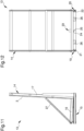
Figure 10 is an axonometric view of a storage station; -
Figure 11 is a side elevation view of the storage station inFigure 10 ; -
Figure 12 is a rear elevation view of the storage station inFigure 10 ; -
Figure 13 is a plan view of the grasping means according to the invention; -
Figure 14 is a side view of the grasping means, in a blocking position. - With particular reference to these figures,
reference numeral 1 globally indicates a piece of equipment for the logistics of slab-shaped articles. - In the context of the present discussion, the term "logistics" relates to the set of maintenance and storage operations of slab-shaped articles aimed at preparing the same for shipment to customers.
- The piece of
equipment 1 is used to move at least one slab-shaped article 2. The slab-shaped article 2 is a solid body having two dimensions prevailing over the third, thickness, and comprising two substantially flat faces opposite each other. - For example, within the ceramic industry, the slab-
shaped articles 2 may have dimensions such that one or more sides may be up to and comprising over three meters long. - The
equipment 1 comprises at least one supplyingplane 3 of at least one slab-shaped article 2. - The supplying
plane 3 is shaped to receive in support a plurality of slab-shaped articles 2 arranged one on top of the other. - In particular, the supplying
plane 3 is adapted to receive the slab-shaped articles 2 by means of appropriate lifting machines, such as e.g., forklift trucks or transpallets or mechanical robots or manually by an operator. - In addition, the
equipment 1 may conveniently further comprise at least onecontainer body 29 positionable on the supplyingplane 3 and adapted to contain a plurality of slab-shaped articles 2. - In more detail, the
container body 29 is adapted to house the slab-shaped articles 2 stacked one on top of the other. - The function of the
container body 29 is to facilitate the transport and positioning of the slab-shaped articles 2 on the supplyingplane 3. - In the embodiment shown in the figures, the
container body 29 is open at the top and allows the slab-shaped article 2 to be taken from the top. - According to the invention, the
equipment 1 also comprises: - at least one
robotic gripping group 4 of the slab-shaped article 2 provided with at least three degrees of freedom and positioned in the proximity of the supplyingplane 3; - movement means 5 of the
gripping group 4 along at least one direction of movement A so as to define at least onework area 6 of thegripping group 4; - a plurality of temporary storage stations 7 of the slab-
shaped article 2 positioned substantially parallel to the direction of movement A; - at least one supporting
frame 8 of the slab-shaped article 2 supported as an integral part to the movement means 5 along the direction of movement A; and - at least one
unloading station 9 of the supportingframe 8. - The
gripping group 4 is adapted to: - take the slab-
shaped article 2 from the supplyingplane 3; - place the slab-
shaped article 2 on at least one of the storage stations 7; and - take the slab-
shaped article 2 from at least one storage station 7 to place it on the supportingframe 8. - In particular, thanks to the movement means 5, the
gripping group 4 can be approached to the supplyingplane 3 and, moreover, being provided with three degrees of freedom, it can be moved along a substantially vertical direction and be rotated to allow the picking up of the slab-shaped article 2. - Thereafter, the
gripping group 4 can be approached to a storage station 7 to deposit thereon the newly picked slab-shaped article 2 or to pick up a slab-shaped article 2 and place it on top of the supportingframe 8 so as to make up afinal frame 30, which is then transferred to theunloading station 9. - In particular, the slab-
shaped articles 2 arriving on the supplyingplane 3 must be moved or stored according to their type and then picked up for marketing or further machining, if necessary. - Conveniently, the movement means 5 comprise at least one pair of
sliding guides 11 extending along the direction of movement A and at least one load-bearingframe 12 associated in a movable and sliding manner with the pair ofsliding guides 11 and supporting thegripping group 4. - Preferably, the direction of movement A is substantially horizontal.
- The aforementioned supplying
plane 3 is arranged along the direction of movement A. - The movement means 5 allow, therefore, the movement of the
gripping group 4 and of the supportingframe 8 in thework area 6, along the direction of movement A, for the transfer of the slab-shapedarticles 2 to and from the storage stations 7. - In more detail, the storage stations 7 are positioned at the
work area 6. - This way, the
gripping group 4 can easily reach the storage stations 7, which are allocated in space so as not to hinder the displacements of the gripping group itself along the direction of movement A. - Conveniently, the
gripping group 4 is movable with respect to the load-bearing frame 12 along a direction of translation T transverse to the direction of movement A when approaching/moving away from the storage stations 7. - The direction of translation T is substantially perpendicular to the direction of movement A.
- In more detail, the
equipment 1 comprises translation means placed between thegripping group 4 and the load-bearing frame 12 and adapted to move the gripping group itself along the direction of translation T. - Advantageously, each storage station 7 comprises at least one
storage frame 13 for the logistics of the slab-shapedarticles 2. - The
storage frame 13 is schematically shown inFigures 1 to 9 , while it is shown in greater detail inFigures 10 to 12 . - The
storage frame 13 is provided with: - at least one holding
frame 14 of one or more slab-shapedarticles 2; - at least one fixed
frame 15, anchored to the ground. - The holding
frame 14 is provided with: - at least one
basic element 16 adapted to receive and support the thickness of the slab-shapedarticle 2; and - at least one
stop element 17 extending transversely to thebasic element 16 and adapted to receive and support at least one face of the slab-shapedarticle 2. - Preferably, the
basic element 16 defines a substantially flat basic surface positioned slightly inclined with respect to a horizontal plane, and thestop element 17 defines a substantially flat stop surface positioned slightly inclined with respect to a vertical plane. - Appropriately, the
basic element 16 and thestop element 17 are arranged so that the basic surface and the stop surface define a substantially right angle with each other. - This arrangement of the
basic element 16 and of thestop element 17 results in the slab-shapedarticle 2, when allocated resting on the holdingframe 14, being positioned slightly inclined with respect to a vertical axis, so as to limit the risk of tipping over and sliding downwards. - Conveniently, the
storage frame 13 comprises removable engagement means 18 for engaging the holdingframe 14 to the fixedframe 15. - The engagement means 18 are adapted to allow the holding
frame 14 to slide with respect to the fixedframe 15 along a substantially horizontal direction of sliding S, and to prevent the holdingframe 14 from lifting with respect to the fixedframe 15. - Precisely, the holding
frame 14 may be alternatively allocated in a first configuration wherein it is associated in a sliding manner with the fixedframe 15 and in a second configuration wherein it is instead disengaged from the fixedframe 15. - Conveniently, during the positioning of the slab-shaped
article 2 on the holdingframe 14 by thegripping group 4, the holdingframe 14 is engaged with the fixedframe 15. - The holding
frame 14, on the other hand, is disengaged from the fixedframe 15 when, e.g., it has to be moved away from thework area 6. - Preferably, the engagement means 18 comprise:
- guidance means 19 associated with one of either the fixed
frame 15 or the holdingframe 14; and - sliding means 20 associated with the other of either the fixed
frame 15 or the holdingframe 14, where the slidingmeans 20 are engageable in a removable manner with the guidance means 19. - In the particular embodiments shown in the figures, the guidance means 19 are associated with the fixed
frame 15 and the slidingmeans 20 are associated with the holdingframe 14. - Precisely, the guidance means 19 comprise at least one pair of substantially C-shaped
guidance elements 21, so as to define a relevant housing seat extending along the direction of sliding S and arranged side by side. - The sliding means 20 comprise at least one pair of rolling
elements 22, e.g. wheels, each of which is insertable in a relevant housing seat. - Precisely, the rolling
elements 22 slide in the housing seat along the direction of sliding S as a result of the engagement of the holdingframe 14 with the fixedframe 15. - At the same time, the upper portion of the housing seat prevents the rolling
elements 22 from exiting theguidance elements 21 by moving upwards. - This way, the holding
frame 14 can slide with respect to the fixedframe 15 without being lifted upwards. - The rolling
elements 22 slide inside their respective housing seats until they contact an end-of-stroke element, arranged at an end portion of eachguidance element 21. - Conveniently, the
storage frame 13 comprises locking means 23 of the holdingframe 14 with respect to the fixedframe 15 along the direction of sliding S. - In more detail, the locking means 23 comprise a locking
element 24 associated with the holdingframe 14 and insertable in astop seat 25 associated with the fixedframe 15. - Suitably, the locking
element 24 and thestop seat 25 are aligned to each other when the holdingframe 14 reaches the end-of-stroke position defined by the end-of-stroke element. - The locking
element 24 is movable between a blocking position, wherein it is engaged in thestop seat 25, and a release position, wherein it is disengaged from thestop seat 25. - The
storage frame 13 comprises gripping means 26 formed on the holdingframe 14 and engageable to allow lifting and moving the holdingframe 14 when disengaged from the fixedframe 15. - Conveniently, the
storage frame 13 comprises restraining means 27 of the slab-shapedarticle 2 deposited on the holdingframe 14. - The restraining means 27 are associated with the holding
frame 14 and are movable between: - at least one restraining configuration wherein they face the
stop element 17; - at least one release configuration wherein they are spaced apart from the
stop element 17 with respect to the restraining configuration, so as to allow the positioning/picking of the slab-shapedarticle 2. - The movement of the restraining means 27 can be done manually by an operator or can be done automatically.
- Precisely, when the
gripping group 4 deposits or picks the slab-shapedarticle 2 on or from thestorage frame 13, the restraining means 27 are positioned in the release configuration so as not to hinder the movement operations of the slab-shapedarticle 2. - Likewise, as a result of the positioning of the slab-shaped
article 2 on thestorage frame 13, the restraining means 27 are placed in the restraining configuration and are arranged in the proximity of or in support on the slab-shapedarticle 2. - This way, the restraining means 27 are able to prevent the slab-shaped
article 2 from falling accidentally from thestorage frame 13. - Advantageously, the
equipment 1 comprises at least one row F of storage stations 7 positioned substantially aligned to each other along the direction of movement A at the point where a lateral edge of thework area 6 is located. - In particular, the row F is arranged laterally to one of the sliding guides 11, which is arranged inside the
work area 6. - In the embodiments shown in the figures, the
equipment 1 comprises at least two rows F arranged on opposite sides to thegripping group 4. - In particular, the rows F are arranged substantially parallel to each other and facing each other.
- More particularly, the
work area 6 is placed between the rows F. - As shown in the figures, each of the sliding guides 11 is arranged inside the
work area 6. - This embodiment ensures that the
gripping group 4 can easily reach the storage stations 7 allocated on opposite sides to thework area 6. - Precisely, the
gripping group 4, after being positioned in the proximity of a storage station 7 arranged on one row F, can easily reach the storage station 7 placed in front without being further moved horizontally, along the direction of movement A or transversely with respect thereto. - This can improve the production output of the
equipment 1 and save time and energy. - Advantageously, the
gripping group 4 is of the type of an anthropomorphic robot. - The
gripping group 4 is, therefore, provided with multiple degrees of freedom and is able to move the slab-shapedarticle 2 in a practical and easy way. Advantageously, thegripping group 4 comprises grasping means 10 of the slab-shapedarticle 2. - In the particular embodiments shown in the figures, the grasping
means 10 are of the type of suction cups. - More particularly, the grasping
means 10 comprise a plurality ofsuction cups 10a and at least one vacuum circuit operationally connected to the suction cups themselves. - Alternative embodiments cannot however be ruled out wherein the grasping
means 10 have different conformation and, for example, may be of the type of hooking elements or grippers. - Specifically, the grasping
means 10 comprise a holdingstructure suction cups 10a. - The grasping means 10 comprise safety means, not shown in detail in the figures, adapted to prevent the slab-shaped
article 2 from falling. - The safety means comprise detection means for detecting the absence of vacuum in at least one of the
suction cups 10a. - In fact, if one of the
suction cups 10a does not perfectly adhere to the slab-shapedarticle 2, the slab-shapedarticle 2 could partially or totally detach from thegripping group 4 and be damaged. - Thanks to the presence of the detection means for detecting the absence of vacuum, the
equipment 1 can be blocked, thus avoiding the movement of an unsafely grasped slab-shapedarticle 2. - Alternatively, or in addition, the safety means may be of the mechanical type and comprise, e.g., a locking element (not shown in the figures) adapted to contact the slab-shaped
article 2, so as to hold it, after it has been grasped. - This way, in the event of partial or complete loss of adhesion between the grasping
means 10 and the slab-shapedarticle 2, the locking element holds the slab-shapedarticle 2 and prevents it from becoming unbalanced or falling during movement. - After the slab-shaped
article 2 has been picked up from the storage station 7, it is placed on the supportingframe 8 to make up thefinal frame 30. - In particular, the supporting
frame 8 is capable of supporting a plurality of slab-shapedarticles 2, which can be easily packed thereon to form thefinal frame 30; after it has reached the unloadingstation 9, thefinal frame 30 can be directly intended for marketing. - Advantageously, the supporting
frame 8 is arranged inside thework area 6. - In particular, the
gripping group 4 and the supportingframe 8 are both mounted on the load-bearing frame 12. - This way, the
gripping group 4 is able to easily position the slab-shapedarticles 2 on the supportingframe 8 after they have been picked up from the respective storage stations 7, without being further moved. - The supporting
frame 8 is mounted in a removable manner on the load-bearing frame 12 and is adapted to be removed from the load-bearing frame itself in order to position thefinal frame 30 at the point where the unloadingstation 9 is located. - For this purpose, the load-
bearing frame 12 is provided with anchoring means of the removable type of the supportingframe 8, not shown in detail in the figures. - The anchoring means are adapted to keep the supporting
frame 8 anchored to the load-bearing frame 12 during movement of the supporting frame itself along the direction of movement A and to allow the removal thereof after the unloadingstation 9 has been reached. - In fact, if necessary, the
gripping group 4 positions the slab-shapedarticles 2 on the supportingframe 8 and, at the end of this operation, the movement means transfer thefinal frame 30 to the unloadingstation 9. Here, by means of special lifting machines, such as, e.g., forklift trucks or transpallets or mechanical robots, thefinal frame 30 is positioned in the unloadingstation 9. - In particular, the unloading
station 9 is represented by an area of the relevant plant on which thefinal frames 30 may be positioned resting on the ground or on appropriate structures. - The supporting
frame 8 comprises: - at least one
basic support 8a which can be positioned on the load-bearing frame 12 and adapted to receive and support the thickness of the slab-shapedarticle 2; and - at least one holding
element 8b extending transversely to thebasic support 8a and adapted to receive and support at least one face of the slab-shapedarticle 2. - In particular, the
basic support 8a is positionable substantially horizontal on the load-bearing frame 12 and the holdingelement 8b extends vertically with respect to the basic support itself, along a median plane of thebasic support 8a. In other words, the supportingframe 8 is substantially shaped as an inverted "T". - Thus, the supporting
frame 8 comprises two support areas for supporting the slab-shapedarticles 2, arranged on opposite sides to the holdingelement 8b. During the positioning operations, each support area faces a respective row F. Conveniently, the supportingframe 8 comprises at least one blocking device of the slab-shapedarticle 2, not shown in detail in the figures, and adapted to keep the slab-shaped article itself anchored to the holdingelement 8b. - In particular, the blocking device is positionable so as to allow the positioning of the slab-shaped
article 2 on the supportingframe 8. - The blocking device has, therefore, the function of preventing the slab-shaped
article 2 from falling accidentally from the supportingframe 8 during the travel along the direction of movement A. - As shown in the figures, the supporting
frame 8 extends along a longitudinal direction and is arranged on the load-bearing frame 12 parallel to the direction of movement A. - This way, the face of the slab-shaped
article 2 lies on a plane substantially parallel to the direction of movement A. - This arrangement makes it possible to optimize the space and reduce the size of the supporting
frame 8 with respect to thework area 6; in addition, this solution provides greater stability to the slab-shapedarticle 2 thus reducing the risk of accidental falling of the same. - According to a possible embodiment, shown in detail in
Figures 13 and 14 , the holdingstructure gripping group 4 is movable between a home position and a blocking position, wherein it faces the holdingelement 8b to hold the slab-shapedarticle 2 arranged in support to the holding element itself. - This way, another function of the grasping
means 10 is to block the slab-shapedarticle 2 on the supportingframe 8 during the movement of the same along the direction of movement A. - In more detail, the holding
structure first structure 31 that is fixed and at least asecond structure 32 supporting thesuction cups 10a and movable with respect to thefirst structure 31 between the home position and the blocking position. - Specifically, the
second structure 32 is hinged to thefirst structure 31. Conveniently, the holdingstructure second structures 32 arranged on opposite sides to thefirst structure 31. - In the blocking position, the
second structures 32 are arranged facing the holdingelement 8b, on opposite sides to the latter. - More specifically, in the blocking position each
second structure 32 faces a respective support area of the supportingframe 8. - In the home position, the
second structure 32 is substantially aligned to thefirst structure 31. In such a position, thefirst structure 31 and thesecond structures 32 are arranged on the same plane and may be moved to the point where a storage station 7 is located to pick up a slab-shapedarticle 2. - In the work position, the holding
structure element 8b and is arranged transversely with respect thereto. In this position, thesecond structure 32 is rotated with respect to thefirst structure 31. - The following is a detailed description of the different embodiments shown in the figures, which are distinguished by the type of supplying
plane 3. - The common elements to all described and shown embodiments are identified below with the same reference numbers.
- In the first embodiment, shown in
Figures 1 to 4 , which is not according to the present invention, the supplyingplane 3 is fixed and is arranged at one end of thework area 6, opposite the unloadingstation 9. -
Figures 5 to 9 , on the other hand, show further embodiments of the present equipment according to the invention, wherein the supplyingplane 3 is movable in translation along the direction of movement A. - According to the embodiments shown in
Figures 5 to 7 , theequipment 1 comprises at least oneconveyor line 28 of the slab-shapedarticle 2 arranged inside thework area 6. - In particular, the
conveyor line 28 extends by at least the entire length of the sliding guides 11, until it reaches at least the unloadingstation 9. Advantageously, theconveyor line 28 is placed between the rows F. - The
conveyor line 28 defines the supplyingplane 3 and is movable along at least one direction of conveyance C substantially parallel to the direction of movement A. - In the particular embodiment shown in the figures, the
conveyor line 28 is, e.g., of the type of a belt conveyor line or the like. - The slab-shaped
article 2 is then placed in support on theconveyor line 28 and is moved towards the grippinggroup 4. - The slab-shaped
articles 2 may be arranged continuously along theconveyor line 28, in succession to each other. - Alternatively or in combination, as shown in
Figure 6 , the slab-shapedarticles 2 may be arranged on theconveyor line 28 stacked on top of each other. - Again, with reference to
Figure 7 , theconveyor line 28 may receive and support thecontainer body 29 containing the slab-shapedarticles 2, which is moved towards the grippinggroup 4. - The
gripping group 4 is adapted to pick up the slab-shapedarticle 2 from theconveyor line 28 and place it on one of the storage stations 7. - The
conveyor line 28 makes it possible to speed up the supplying operations of the slab-shapedarticles 2, which are, in fact, transferred onto it and promptly picked up by means of thegripping group 4. - In fact, this solution makes it possible to reduce the number of travels made by the
gripping group 4 to pick up the slab-shapedarticles 2 to be stored. - The
conveyor line 28 moves the slab-shapedarticle 2 until it reaches the relevant storage station 7, where it is picked up by thegripping group 4. Conveniently, theconveyor line 28 is positioned at a lower height than the load-bearing frame 12 so as to pass thereunder. - In other words, the load-
bearing frame 12 is movable along the slidingguides 11 above theconveyor line 28. - With reference to the embodiment shown in
Figure 7 , at the end of the positioning operations, theempty container body 29 is moved again along the direction of movement A, away from thegripping group 4, by passing thereunder. - Conveniently, the
conveyor line 28 is arranged at a distance of between 10 cm and 110 cm from the load-bearing frame 12. - Appropriately, the
conveyor line 28 is arranged at a distance from the load-bearing frame 12 such that thecontainer body 29 is allowed to pass thereunder. According to the embodiments shown inFigures 8 and9 , theequipment 1 comprises at least onemovable device 33, defining the supplyingplane 3. - The
movable device 33 is associated in a sliding manner with the sliding guides 11. - The
movable device 33 is of the type of a trolley movable along the direction of movement A in either direction. - The
movable device 33 is, therefore, movable between one end of thework area 6, wherein it receives the slab-shapedarticles 2, up to a storage station 7 on which the slab-shapedarticles 2 are to be placed. - Similarly to what described above, the
movable device 33 may receive and support thecontainer body 29 provided with the slab-shapedarticles 2 to be positioned. - According to the embodiment shown in
Figure 8 , themovable device 33 is movable independently with respect to thegripping group 4 along the direction of movement A. - This solution allows loading the slab-shaped
articles 2 on themovable device 33 while allowing thegripping group 4 to carry out its own operations without interruption. -
Figure 9 shows a further embodiment wherein, on the contrary, themovable device 33 is movable locked together with thegripping group 4. - Specifically, the
movable device 33 is locked together with the load-bearing frame 12. - Conveniently, the
movable device 33 is arranged opposite the supportingframe 8 with respect to thegripping group 4. - Therefore, the
movable device 33 and thegripping group 4 move simultaneously in thework area 6 along the direction of movement A. - This embodiment allows easily positioning the slab-shaped
articles 2 arranged on themovable device 33 even on different storage stations 7. - The operation of the
equipment 1 in performing the process according to the invention is defined inclaim 8. - The process first involves a phase of supply of a piece of
equipment 1 according to the embodiments described above. - Next, the process comprises the phases of:
- supplying a plurality of slab-shaped
articles 2; - collecting one of the slab-shaped
articles 2 from the supplyingplane 3; - placing the slab-shaped
article 2 on one of the storage stations 7; and - picking one of the slab-shaped
articles 2 from one of the storage stations 7 to place it on the supportingframe 8. - The aforementioned collecting, placing and picking phases are repeated in order to make up a
final frame 30. - Finally, the process comprises a phase of unloading the
final frame 30 in the unloadingstation 9. - Initially, the process comprises a phase of blocking the holding
frame 14 to the fixedframe 15 of the storage stations 7, in order to prepare them for the subsequent placing phases. - The holding
frame 14 is approached to the fixedframe 15 and, thereafter, the lockingelement 24 is inserted inside thestop seat 25 thereby blocking the holdingframe 14 to the fixedframe 15. - At this point, the
storage frame 13 is ready for the placement of the slab-shapedarticles 2. - The slab-shaped
articles 2 are arranged on the supplyingplane 3. - The process may conveniently comprise a phase of supplying at least one
container body 29 to be emptied, containing a plurality of slab-shapedarticles 2 to be positioned. Thecontainer body 29 to be emptied is arranged on the supplyingplane 3. - The phase of collecting provides for the
gripping group 4 picking up a slab-shapedarticle 2 from the supplyingplane 3 using the graspingmeans 10. - Conveniently, according to the first embodiment, wherein the supplying
plane 3 is fixed, the phase of collecting comprises a phase of translation of thegripping group 4 with respect to the supplyingplane 3 along the direction of movement A. - Referring to the first embodiment shown in
Figures 1 to 4 , thegripping group 4 translates to the end of thework area 6 to pick up each slab-shapedarticle 2. According to the embodiments shown inFigures 5 to 8 , the phase of collecting comprises at least one phase of sliding of the supplyingplane 3 with respect to thegripping group 4 along the direction of movement A. - It is easy to understand that such solutions may further provide for the translation of the
gripping group 4 with respect to the supplyingplane 3, if necessary, to facilitate and speed up the pick up of the slab-shapedarticle 2. Conveniently, the phase of sliding may comprise approaching thecontainer body 29 to be emptied to thegripping group 4. - The
container body 29 is moved along the direction of movement A, on theconveyor line 28 or on themovable device 33. - In particular, with reference to the embodiment shown in
Figures 5 to 7 , the slab-shapedarticles 2 positioned on theconveyor line 28 slide close to thegripping group 4 and are arranged at the respective storage stations 7. - In the fourth embodiment shown in
Figure 8 , themovable device 33 translates from the end of thework area 6, where it receives the slab-shapedarticles 2, up to the storage station 7. - According to the embodiment shown in
Figure 9 , on the other hand, thegripping group 4 and the supplyingplane 3 move locked together. Such a solution provides for the load-bearing frame 12 translating towards the end of thework area 6 where a plurality of slab-shapedarticles 2 are placed on themovable device 33. At that point, thegripping group 4 and the supplyingplane 3 translate towards the storage stations to perform the positioning operations. - In each of the described embodiments, the
gripping group 4 places the slab-shapedarticles 2 in the relevant storage stations 7. - In particular, thanks to the grasping
means 10, thegripping group 4 collects a slab-shapedarticle 2 from the supplyingplane 3 and deposits it on the holdingframe 14 so that its thickness gets in contact with thebasic element 16 and one of its faces stops on thestop element 17. - At the end of the phase of collecting, the process comprises a phase of moving an
empty container body 29 away from thegripping group 4. - In the embodiment shown in
Figures 1 to 7 , the phase of moving away is performed in a direction concordant with the direction of movement A. Specifically, the phase of moving away comprises a phase of transit of theempty container body 29 below thegripping group 4. As exposed above, in fact, theconveyor line 28 is arranged with respect to the load-bearing frame 12 at a distance such as to allow the passage of thecontainer body 29 below the latter. In the embodiment shown inFigures 8 and9 , on the other hand, the phase of moving away is carried out in the opposite direction to the direction of movement A. - In particular, the
movable device 33 translates back to the end of thework area 6 to receive new slab-shapedarticles 2. - At the same time, the
gripping group 4 picks up the slab-shapedarticles 2 required to make up thefinal frame 30, by means of the graspingmeans 10, and arranges them on the supportingframe 8. - For this purpose, the blocking device is appropriately positioned to allow the slab-shaped
article 2 to be positioned on the supportingframe 8 and to anchor it to the supporting frame itself during the movement along the direction of movement A. - Alternatively or in combination, the
second structures 32 are moved to the blocking position to keep the slab-shapedarticles 2 in support to the holdingelement 8b. - Upon completion of these operations, the movement means 5 bring the
final frame 30 to the unloadingstation 9, wherein it is removed from the load-bearing frame 12 to be moved to further machining stations. - It has in practice been ascertained that the described invention achieves the intended objects and, in particular, the fact is emphasized that the equipment allows moving the slab-shaped articles in an easy and safe way, thus limiting the risk of breakage or damage.
- Moreover, the presence of the supporting frame, mounted on the load-bearing frame of the gripping group and the possibility of packing the slab-shaped articles thereon, allow an optimization of the machining timelines and an increase in the production output of the logistic plant.
Claims (13)
- Equipment (1) for the logistics of slab-shaped articles, comprising:- at least one supplying plane (3) of at least one slab-shaped article (2);- at least one robotic gripping group (4) of said slab-shaped article (2) provided with at least three degrees of freedom and positioned in the proximity of said supplying plane (3);- movement means (5) of said gripping group (4) along at least one direction of movement (A) so as to define at least one work area (6) of said gripping group (4);- a plurality of temporary storage stations (7) of said slab-shaped article (2) positioned substantially parallel to said direction of movement (A);- at least one supporting frame (8) of said slab-shaped article (2) supported as an integral part to said movement means (5) along said direction of movement (A); and- at least one unloading station (9) of said supporting frame (8);wherein said gripping group (4) is adapted to:- take said slab-shaped article (2) from said supplying plane (3);- place said slab-shaped article (2) on at least one of said storage stations (7); and- take said slab-shaped article (2) from at least one of said storage stations (7) to place it on said supporting frame (8)characterized by the fact that said supplying plane (3) is movable in translation along said direction of movement (A).
- Equipment (1) according to claim 1, characterized by the fact that said gripping group (4) comprises grasping means (10) of said slab-shaped article (2).
- Equipment (1) according to claim 1 or 2, characterized by the fact that said grasping means (10) comprise a holding structure (31,32) supporting said suction cups (10a), movable between a home position and a blocking position, wherein it faces said holding element (8b) to hold said slab-shaped article (2) arranged in support to the holding element itself.
- Equipment (1) according to claim 3, characterized by the fact that said holding structure (31,32) comprises a first structure (31) that is fixed and at least a second structure (32) supporting said suction cups (10a), wherein said second structure (32) is movable with respect to said first structure (31) between said home position and said blocking position, said second structure (32) being hinged to said first structure (31).
- Equipment (1) according to one or more of the preceding claims, characterized by the fact that it comprises at least one conveyor line (28) of said slab-shaped article (2) arranged inside said work area (6), defining said supplying plane (3) and movable along at least one direction of conveyance (C) substantially parallel to said direction of movement (A), wherein said conveyor line (28) is positioned at a lower height than said load-bearing frame (12) so as to pass thereunder, said gripping group (4) being adapted to pick said slab-shaped article (2) from said conveyor line (28) to position it on one of said storage stations (7).
- Equipment (1) according to one or more of the preceding claims, characterized by the fact that it comprises at least one movable device (33), defining said supplying plane (3) and associated in a sliding manner with said sliding guides (11).
- Equipment (1) according to claim 6, characterized by the fact that said movable device (33) is movable locked together with said gripping group (4) along said direction of movement (A).
- Process for the logistics of slab-shaped articles, comprising the phases of:- supplying a piece of equipment (1) according to one or more of the preceding claims;- supplying a plurality of slab-shaped articles (2);- collecting one of said slab-shaped articles (2) from said supplying plane (3);- placing said slab-shaped articles (2) on one of said storage stations (7); and- picking one of said slab-shaped articles (2) from one of said storage stations (7) to place it on said supporting frame (8);- repeating the phases of collecting, placing and picking to make up a final frame (30);- unloading said final frame (30) in said unloading station (9);characterized by the fact that said phase of collecting comprises at least one phase of sliding of said supplying plane (3) with respect to said gripping group (4) along said direction of movement (A).
- Process according to claim 8, characterized by the fact that said phase of collecting comprises a phase of translation of said gripping group (4) with respect to said supplying plane (3) along said direction of movement (A).
- Process according to one or more of claims 8 or 9, characterized by the fact that it comprises a phase of supplying at least one container body (29) to be emptied, containing a plurality of slab-shaped articles (2) to be positioned.
- Process according to claim 10, characterized by the fact that said phase of sliding comprises a phase of movement of said container body (29) to be emptied, approaching said gripping group (4).
- Process according to claim 10 or 11, characterized by the fact that it comprises a phase of moving an empty container body (29) away from said gripping group (4).
- Process according to claim 12, characterized by the fact that said phase of moving away comprises a phase of transit of said empty container body (29) below said gripping group (4).
Applications Claiming Priority (2)
| Application Number | Priority Date | Filing Date | Title |
|---|---|---|---|
| IT102019000024337A IT201900024337A1 (en) | 2019-12-17 | 2019-12-17 | EQUIPMENT FOR THE LOGISTICS OF LASTRIFORMS |
| PCT/IB2020/062022 WO2021124145A1 (en) | 2019-12-17 | 2020-12-16 | Equipment for the logistics of slab-shaped articles |
Publications (3)
| Publication Number | Publication Date |
|---|---|
| EP4077180A1 EP4077180A1 (en) | 2022-10-26 |
| EP4077180C0 EP4077180C0 (en) | 2024-07-24 |
| EP4077180B1 true EP4077180B1 (en) | 2024-07-24 |
Family
ID=70228462
Family Applications (1)
| Application Number | Title | Priority Date | Filing Date |
|---|---|---|---|
| EP20833959.8A Active EP4077180B1 (en) | 2019-12-17 | 2020-12-16 | Equipment for the logistics of slab-shaped articles |
Country Status (5)
| Country | Link |
|---|---|
| US (1) | US12421055B2 (en) |
| EP (1) | EP4077180B1 (en) |
| ES (1) | ES2986942T3 (en) |
| IT (1) | IT201900024337A1 (en) |
| WO (1) | WO2021124145A1 (en) |
Families Citing this family (2)
| Publication number | Priority date | Publication date | Assignee | Title |
|---|---|---|---|---|
| US12258216B2 (en) * | 2020-06-11 | 2025-03-25 | Nimble Robotics, Inc. | Automated delivery vehicle |
| US20240239603A1 (en) * | 2023-01-12 | 2024-07-18 | Contemporary Amperex Technology Co., Limited | Storage pallet and automated guided vehicle |
Citations (8)
| Publication number | Priority date | Publication date | Assignee | Title |
|---|---|---|---|---|
| FR2286767A1 (en) | 1974-10-04 | 1976-04-30 | Bygg Och Transportekonomie Ab | SYSTEM FOR THE ORDER AND MECHANICAL PACKAGING AND PACKAGING OF PRODUCTS |
| EP0302205A2 (en) | 1987-08-04 | 1989-02-08 | Messerschmitt-Bölkow-Blohm Gesellschaft mit beschränkter Haftung | Driverless conveying vehicle |
| DE19945338A1 (en) | 1999-09-22 | 2001-04-12 | Grenzebach Maschb Gmbh | Stacking device for glass plates has handling robots spaced along glass plate transport path for rotating glass plates between horizontal and vertical position selectively operated in synchronism |
| DE102005060452A1 (en) | 2005-12-17 | 2007-06-28 | Armatec Vierhaus Gmbh | Handling unit for surface materials, especially glass sheets, has carrier frame with evacuable suction heads to hold the sheets that can be swung between horizontal and vertical positions |
| EP2308782A1 (en) | 2009-10-06 | 2011-04-13 | Bottero S.p.A. | System for feeding glass sheets to at least one sheet processing line and production plant comprising this system |
| US20130156531A1 (en) | 2010-08-27 | 2013-06-20 | Kawasaki Jukogyo Kabushiki Kaisha | Plate-shaped member storage rack, plate-shaped member transfer facility, and plate-shaped member storing method |
| US20150274420A1 (en) | 2012-10-22 | 2015-10-01 | Grenzebach Maschinenbau Gmbh | Apparatus and method for quickly transferring plates |
| EP3275810A1 (en) | 2016-07-25 | 2018-01-31 | Movetro S.r.l. | Conveyor carriage for sheet-like elements, apparatus and method for the management of a warehouse of sheet-like elements comprising said carriage |
Family Cites Families (7)
| Publication number | Priority date | Publication date | Assignee | Title |
|---|---|---|---|---|
| JP3137999B2 (en) * | 1991-04-12 | 2001-02-26 | 株式会社アマダ | Work loading / unloading device for processing machine |
| US6059092A (en) * | 1997-12-23 | 2000-05-09 | Fanuc Robotics North America, Inc. | Material handling robot and rail assembly |
| US7153085B2 (en) * | 2004-12-22 | 2006-12-26 | Aidco International, Inc. | Multi-modal package handling tool and system |
| CA2630133A1 (en) * | 2007-04-27 | 2008-10-27 | Axium Inc. | Order picking system |
| DE202013103555U1 (en) * | 2013-08-07 | 2014-11-13 | Kuka Systems Gmbh | logistics system |
| IT201700065721A1 (en) * | 2017-06-14 | 2018-12-14 | Granitifiandre Spa | STATION AND PACKAGING METHOD FOR CERAMIC SHEETS |
| MA56519A (en) * | 2019-06-19 | 2022-04-27 | Lk Lab S R L | EQUIPMENT AND METHOD FOR LOGISTICS OF SLAB-SHAPED ARTICLES |
-
2019
- 2019-12-17 IT IT102019000024337A patent/IT201900024337A1/en unknown
-
2020
- 2020-12-16 US US17/786,090 patent/US12421055B2/en active Active
- 2020-12-16 EP EP20833959.8A patent/EP4077180B1/en active Active
- 2020-12-16 WO PCT/IB2020/062022 patent/WO2021124145A1/en not_active Ceased
- 2020-12-16 ES ES20833959T patent/ES2986942T3/en active Active
Patent Citations (8)
| Publication number | Priority date | Publication date | Assignee | Title |
|---|---|---|---|---|
| FR2286767A1 (en) | 1974-10-04 | 1976-04-30 | Bygg Och Transportekonomie Ab | SYSTEM FOR THE ORDER AND MECHANICAL PACKAGING AND PACKAGING OF PRODUCTS |
| EP0302205A2 (en) | 1987-08-04 | 1989-02-08 | Messerschmitt-Bölkow-Blohm Gesellschaft mit beschränkter Haftung | Driverless conveying vehicle |
| DE19945338A1 (en) | 1999-09-22 | 2001-04-12 | Grenzebach Maschb Gmbh | Stacking device for glass plates has handling robots spaced along glass plate transport path for rotating glass plates between horizontal and vertical position selectively operated in synchronism |
| DE102005060452A1 (en) | 2005-12-17 | 2007-06-28 | Armatec Vierhaus Gmbh | Handling unit for surface materials, especially glass sheets, has carrier frame with evacuable suction heads to hold the sheets that can be swung between horizontal and vertical positions |
| EP2308782A1 (en) | 2009-10-06 | 2011-04-13 | Bottero S.p.A. | System for feeding glass sheets to at least one sheet processing line and production plant comprising this system |
| US20130156531A1 (en) | 2010-08-27 | 2013-06-20 | Kawasaki Jukogyo Kabushiki Kaisha | Plate-shaped member storage rack, plate-shaped member transfer facility, and plate-shaped member storing method |
| US20150274420A1 (en) | 2012-10-22 | 2015-10-01 | Grenzebach Maschinenbau Gmbh | Apparatus and method for quickly transferring plates |
| EP3275810A1 (en) | 2016-07-25 | 2018-01-31 | Movetro S.r.l. | Conveyor carriage for sheet-like elements, apparatus and method for the management of a warehouse of sheet-like elements comprising said carriage |
Also Published As
| Publication number | Publication date |
|---|---|
| ES2986942T3 (en) | 2024-11-13 |
| EP4077180C0 (en) | 2024-07-24 |
| WO2021124145A1 (en) | 2021-06-24 |
| IT201900024337A1 (en) | 2021-06-17 |
| EP4077180A1 (en) | 2022-10-26 |
| US20230050724A1 (en) | 2023-02-16 |
| US12421055B2 (en) | 2025-09-23 |
Similar Documents
| Publication | Publication Date | Title |
|---|---|---|
| EP3986814B1 (en) | Equipment and process for the logistics of slab-shaped articles | |
| CN103889865B (en) | Device for multiple-level stack base | |
| CN104640792B (en) | Device for multi-layer stacking of bases | |
| US12172304B2 (en) | Automated system for handling containers with product loading | |
| CN104661940B (en) | For the device to base multiple-level stack | |
| US8801358B2 (en) | Method and loading system for order-picking articles onto destination load carriers | |
| US11180327B2 (en) | Method for automatically stacking packages in layers on a support | |
| EP3965997B1 (en) | Sorting system for a machine tool, machine tool and method for sorting cut parts | |
| US11111086B2 (en) | Glass stacking systems and methods | |
| EP4077180B1 (en) | Equipment for the logistics of slab-shaped articles | |
| US12070828B2 (en) | Cell and method for operating a cell of at least two linked horizontal machining centers | |
| JPS6145826A (en) | Article transferring robot | |
| US12122613B2 (en) | Device and process for automated loading and unloading of parcels | |
| RU2817775C2 (en) | Equipment and method for logistic products in form of plates | |
| JP5811838B2 (en) | Goods storage equipment | |
| CN214166351U (en) | Automatic blank storage system | |
| CA3153107C (en) | Cell and method for operating a cell of at least two linked horizontal machining centers | |
| RU2813504C9 (en) | Robotic palletiser | |
| RU2813504C1 (en) | Robotic palletiser | |
| CN211687205U (en) | Device for processing groups of articles and/or layers of articles | |
| JPH0573651B2 (en) | ||
| JPH0659340U (en) | Robot system for article palletizing | |
| IT201900009540A1 (en) | EQUIPMENT FOR THE LOGISTICS OF LASTRIFORMS | |
| JPH07206109A (en) | Handling system for wire coil processing | |
| JPH07315579A (en) | Carrying device for plate and object to be stored in automatic warehouse |
Legal Events
| Date | Code | Title | Description |
|---|---|---|---|
| STAA | Information on the status of an ep patent application or granted ep patent |
Free format text: STATUS: UNKNOWN |
|
| STAA | Information on the status of an ep patent application or granted ep patent |
Free format text: STATUS: THE INTERNATIONAL PUBLICATION HAS BEEN MADE |
|
| PUAI | Public reference made under article 153(3) epc to a published international application that has entered the european phase |
Free format text: ORIGINAL CODE: 0009012 |
|
| STAA | Information on the status of an ep patent application or granted ep patent |
Free format text: STATUS: REQUEST FOR EXAMINATION WAS MADE |
|
| 17P | Request for examination filed |
Effective date: 20220715 |
|
| AK | Designated contracting states |
Kind code of ref document: A1 Designated state(s): AL AT BE BG CH CY CZ DE DK EE ES FI FR GB GR HR HU IE IS IT LI LT LU LV MC MK MT NL NO PL PT RO RS SE SI SK SM TR |
|
| DAV | Request for validation of the european patent (deleted) | ||
| DAX | Request for extension of the european patent (deleted) | ||
| GRAP | Despatch of communication of intention to grant a patent |
Free format text: ORIGINAL CODE: EPIDOSNIGR1 |
|
| STAA | Information on the status of an ep patent application or granted ep patent |
Free format text: STATUS: GRANT OF PATENT IS INTENDED |
|
| INTG | Intention to grant announced |
Effective date: 20240202 |
|
| GRAS | Grant fee paid |
Free format text: ORIGINAL CODE: EPIDOSNIGR3 |
|
| GRAA | (expected) grant |
Free format text: ORIGINAL CODE: 0009210 |
|
| STAA | Information on the status of an ep patent application or granted ep patent |
Free format text: STATUS: THE PATENT HAS BEEN GRANTED |
|
| AK | Designated contracting states |
Kind code of ref document: B1 Designated state(s): AL AT BE BG CH CY CZ DE DK EE ES FI FR GB GR HR HU IE IS IT LI LT LU LV MC MK MT NL NO PL PT RO RS SE SI SK SM TR |
|
| REG | Reference to a national code |
Ref country code: GB Ref legal event code: FG4D |
|
| REG | Reference to a national code |
Ref country code: CH Ref legal event code: EP |
|
| REG | Reference to a national code |
Ref country code: DE Ref legal event code: R096 Ref document number: 602020034611 Country of ref document: DE |
|
| REG | Reference to a national code |
Ref country code: IE Ref legal event code: FG4D |
|
| U01 | Request for unitary effect filed |
Effective date: 20240805 |
|
| U07 | Unitary effect registered |
Designated state(s): AT BE BG DE DK EE FI FR IT LT LU LV MT NL PT SE SI Effective date: 20240821 |
|
| REG | Reference to a national code |
Ref country code: ES Ref legal event code: FG2A Ref document number: 2986942 Country of ref document: ES Kind code of ref document: T3 Effective date: 20241113 |
|
| PG25 | Lapsed in a contracting state [announced via postgrant information from national office to epo] |
Ref country code: NO Free format text: LAPSE BECAUSE OF FAILURE TO SUBMIT A TRANSLATION OF THE DESCRIPTION OR TO PAY THE FEE WITHIN THE PRESCRIBED TIME-LIMIT Effective date: 20241024 |
|
| U20 | Renewal fee for the european patent with unitary effect paid |
Year of fee payment: 5 Effective date: 20241212 |
|
| PG25 | Lapsed in a contracting state [announced via postgrant information from national office to epo] |
Ref country code: PL Free format text: LAPSE BECAUSE OF FAILURE TO SUBMIT A TRANSLATION OF THE DESCRIPTION OR TO PAY THE FEE WITHIN THE PRESCRIBED TIME-LIMIT Effective date: 20240724 Ref country code: GR Free format text: LAPSE BECAUSE OF FAILURE TO SUBMIT A TRANSLATION OF THE DESCRIPTION OR TO PAY THE FEE WITHIN THE PRESCRIBED TIME-LIMIT Effective date: 20241025 |
|
| PG25 | Lapsed in a contracting state [announced via postgrant information from national office to epo] |
Ref country code: IS Free format text: LAPSE BECAUSE OF FAILURE TO SUBMIT A TRANSLATION OF THE DESCRIPTION OR TO PAY THE FEE WITHIN THE PRESCRIBED TIME-LIMIT Effective date: 20241124 |
|
| PG25 | Lapsed in a contracting state [announced via postgrant information from national office to epo] |
Ref country code: HR Free format text: LAPSE BECAUSE OF FAILURE TO SUBMIT A TRANSLATION OF THE DESCRIPTION OR TO PAY THE FEE WITHIN THE PRESCRIBED TIME-LIMIT Effective date: 20240724 |
|
| PG25 | Lapsed in a contracting state [announced via postgrant information from national office to epo] |
Ref country code: RS Free format text: LAPSE BECAUSE OF FAILURE TO SUBMIT A TRANSLATION OF THE DESCRIPTION OR TO PAY THE FEE WITHIN THE PRESCRIBED TIME-LIMIT Effective date: 20241024 |
|
| PG25 | Lapsed in a contracting state [announced via postgrant information from national office to epo] |
Ref country code: RS Free format text: LAPSE BECAUSE OF FAILURE TO SUBMIT A TRANSLATION OF THE DESCRIPTION OR TO PAY THE FEE WITHIN THE PRESCRIBED TIME-LIMIT Effective date: 20241024 Ref country code: PL Free format text: LAPSE BECAUSE OF FAILURE TO SUBMIT A TRANSLATION OF THE DESCRIPTION OR TO PAY THE FEE WITHIN THE PRESCRIBED TIME-LIMIT Effective date: 20240724 Ref country code: NO Free format text: LAPSE BECAUSE OF FAILURE TO SUBMIT A TRANSLATION OF THE DESCRIPTION OR TO PAY THE FEE WITHIN THE PRESCRIBED TIME-LIMIT Effective date: 20241024 Ref country code: IS Free format text: LAPSE BECAUSE OF FAILURE TO SUBMIT A TRANSLATION OF THE DESCRIPTION OR TO PAY THE FEE WITHIN THE PRESCRIBED TIME-LIMIT Effective date: 20241124 Ref country code: HR Free format text: LAPSE BECAUSE OF FAILURE TO SUBMIT A TRANSLATION OF THE DESCRIPTION OR TO PAY THE FEE WITHIN THE PRESCRIBED TIME-LIMIT Effective date: 20240724 Ref country code: GR Free format text: LAPSE BECAUSE OF FAILURE TO SUBMIT A TRANSLATION OF THE DESCRIPTION OR TO PAY THE FEE WITHIN THE PRESCRIBED TIME-LIMIT Effective date: 20241025 |
|
| PG25 | Lapsed in a contracting state [announced via postgrant information from national office to epo] |
Ref country code: RO Free format text: LAPSE BECAUSE OF FAILURE TO SUBMIT A TRANSLATION OF THE DESCRIPTION OR TO PAY THE FEE WITHIN THE PRESCRIBED TIME-LIMIT Effective date: 20240724 Ref country code: SM Free format text: LAPSE BECAUSE OF FAILURE TO SUBMIT A TRANSLATION OF THE DESCRIPTION OR TO PAY THE FEE WITHIN THE PRESCRIBED TIME-LIMIT Effective date: 20240724 |
|
| PGFP | Annual fee paid to national office [announced via postgrant information from national office to epo] |
Ref country code: ES Payment date: 20250102 Year of fee payment: 5 |
|
| PG25 | Lapsed in a contracting state [announced via postgrant information from national office to epo] |
Ref country code: CZ Free format text: LAPSE BECAUSE OF FAILURE TO SUBMIT A TRANSLATION OF THE DESCRIPTION OR TO PAY THE FEE WITHIN THE PRESCRIBED TIME-LIMIT Effective date: 20240724 |
|
| PLBI | Opposition filed |
Free format text: ORIGINAL CODE: 0009260 |
|
| PG25 | Lapsed in a contracting state [announced via postgrant information from national office to epo] |
Ref country code: SK Free format text: LAPSE BECAUSE OF FAILURE TO SUBMIT A TRANSLATION OF THE DESCRIPTION OR TO PAY THE FEE WITHIN THE PRESCRIBED TIME-LIMIT Effective date: 20240724 |
|
| PLAX | Notice of opposition and request to file observation + time limit sent |
Free format text: ORIGINAL CODE: EPIDOSNOBS2 |
|
| 26 | Opposition filed |
Opponent name: SYSTEM CERAMICS S.P.A. Effective date: 20250417 |
|
| PG25 | Lapsed in a contracting state [announced via postgrant information from national office to epo] |
Ref country code: MC Free format text: LAPSE BECAUSE OF FAILURE TO SUBMIT A TRANSLATION OF THE DESCRIPTION OR TO PAY THE FEE WITHIN THE PRESCRIBED TIME-LIMIT Effective date: 20240724 |
|
| REG | Reference to a national code |
Ref country code: CH Ref legal event code: PL |
|
| GBPC | Gb: european patent ceased through non-payment of renewal fee |
Effective date: 20241216 |
|
| PLBB | Reply of patent proprietor to notice(s) of opposition received |
Free format text: ORIGINAL CODE: EPIDOSNOBS3 |
|
| PG25 | Lapsed in a contracting state [announced via postgrant information from national office to epo] |
Ref country code: GB Free format text: LAPSE BECAUSE OF NON-PAYMENT OF DUE FEES Effective date: 20241216 |
|
| PG25 | Lapsed in a contracting state [announced via postgrant information from national office to epo] |
Ref country code: CH Free format text: LAPSE BECAUSE OF NON-PAYMENT OF DUE FEES Effective date: 20241231 |
|
| PG25 | Lapsed in a contracting state [announced via postgrant information from national office to epo] |
Ref country code: IE Free format text: LAPSE BECAUSE OF NON-PAYMENT OF DUE FEES Effective date: 20241216 |
|
| PLAB | Opposition data, opponent's data or that of the opponent's representative modified |
Free format text: ORIGINAL CODE: 0009299OPPO |
|
| R26 | Opposition filed (corrected) |
Opponent name: SYSTEM CERAMICS S.P.A. Effective date: 20250417 |
|
| PGFP | Annual fee paid to national office [announced via postgrant information from national office to epo] |
Ref country code: TR Payment date: 20251216 Year of fee payment: 6 |
|
| U20 | Renewal fee for the european patent with unitary effect paid |
Year of fee payment: 6 Effective date: 20251217 |