EP4077034B1 - Electric vehicle, charging station and method of exchanging power between the vehicle and the station - Google Patents
Electric vehicle, charging station and method of exchanging power between the vehicle and the station Download PDFInfo
- Publication number
- EP4077034B1 EP4077034B1 EP20815802.2A EP20815802A EP4077034B1 EP 4077034 B1 EP4077034 B1 EP 4077034B1 EP 20815802 A EP20815802 A EP 20815802A EP 4077034 B1 EP4077034 B1 EP 4077034B1
- Authority
- EP
- European Patent Office
- Prior art keywords
- vehicle
- station
- power
- terminal
- voltage
- Prior art date
- Legal status (The legal status is an assumption and is not a legal conclusion. Google has not performed a legal analysis and makes no representation as to the accuracy of the status listed.)
- Active
Links
- 238000000034 method Methods 0.000 title claims description 6
- 238000012546 transfer Methods 0.000 description 23
- 239000013256 coordination polymer Substances 0.000 description 15
- 230000010287 polarization Effects 0.000 description 6
- 239000004020 conductor Substances 0.000 description 4
- 230000002441 reversible effect Effects 0.000 description 4
- 238000006243 chemical reaction Methods 0.000 description 3
- 238000010586 diagram Methods 0.000 description 3
- 101100536354 Drosophila melanogaster tant gene Proteins 0.000 description 1
- 230000002457 bidirectional effect Effects 0.000 description 1
- 238000004891 communication Methods 0.000 description 1
- 230000001143 conditioned effect Effects 0.000 description 1
- 238000012986 modification Methods 0.000 description 1
- 230000004048 modification Effects 0.000 description 1
- 230000007935 neutral effect Effects 0.000 description 1
- 238000012360 testing method Methods 0.000 description 1
Images


Classifications
-
- B—PERFORMING OPERATIONS; TRANSPORTING
- B60—VEHICLES IN GENERAL
- B60L—PROPULSION OF ELECTRICALLY-PROPELLED VEHICLES; SUPPLYING ELECTRIC POWER FOR AUXILIARY EQUIPMENT OF ELECTRICALLY-PROPELLED VEHICLES; ELECTRODYNAMIC BRAKE SYSTEMS FOR VEHICLES IN GENERAL; MAGNETIC SUSPENSION OR LEVITATION FOR VEHICLES; MONITORING OPERATING VARIABLES OF ELECTRICALLY-PROPELLED VEHICLES; ELECTRIC SAFETY DEVICES FOR ELECTRICALLY-PROPELLED VEHICLES
- B60L53/00—Methods of charging batteries, specially adapted for electric vehicles; Charging stations or on-board charging equipment therefor; Exchange of energy storage elements in electric vehicles
- B60L53/10—Methods of charging batteries, specially adapted for electric vehicles; Charging stations or on-board charging equipment therefor; Exchange of energy storage elements in electric vehicles characterised by the energy transfer between the charging station and the vehicle
- B60L53/14—Conductive energy transfer
- B60L53/18—Cables specially adapted for charging electric vehicles
-
- B—PERFORMING OPERATIONS; TRANSPORTING
- B60—VEHICLES IN GENERAL
- B60L—PROPULSION OF ELECTRICALLY-PROPELLED VEHICLES; SUPPLYING ELECTRIC POWER FOR AUXILIARY EQUIPMENT OF ELECTRICALLY-PROPELLED VEHICLES; ELECTRODYNAMIC BRAKE SYSTEMS FOR VEHICLES IN GENERAL; MAGNETIC SUSPENSION OR LEVITATION FOR VEHICLES; MONITORING OPERATING VARIABLES OF ELECTRICALLY-PROPELLED VEHICLES; ELECTRIC SAFETY DEVICES FOR ELECTRICALLY-PROPELLED VEHICLES
- B60L53/00—Methods of charging batteries, specially adapted for electric vehicles; Charging stations or on-board charging equipment therefor; Exchange of energy storage elements in electric vehicles
- B60L53/10—Methods of charging batteries, specially adapted for electric vehicles; Charging stations or on-board charging equipment therefor; Exchange of energy storage elements in electric vehicles characterised by the energy transfer between the charging station and the vehicle
- B60L53/14—Conductive energy transfer
- B60L53/16—Connectors, e.g. plugs or sockets, specially adapted for charging electric vehicles
-
- B—PERFORMING OPERATIONS; TRANSPORTING
- B60—VEHICLES IN GENERAL
- B60L—PROPULSION OF ELECTRICALLY-PROPELLED VEHICLES; SUPPLYING ELECTRIC POWER FOR AUXILIARY EQUIPMENT OF ELECTRICALLY-PROPELLED VEHICLES; ELECTRODYNAMIC BRAKE SYSTEMS FOR VEHICLES IN GENERAL; MAGNETIC SUSPENSION OR LEVITATION FOR VEHICLES; MONITORING OPERATING VARIABLES OF ELECTRICALLY-PROPELLED VEHICLES; ELECTRIC SAFETY DEVICES FOR ELECTRICALLY-PROPELLED VEHICLES
- B60L53/00—Methods of charging batteries, specially adapted for electric vehicles; Charging stations or on-board charging equipment therefor; Exchange of energy storage elements in electric vehicles
- B60L53/20—Methods of charging batteries, specially adapted for electric vehicles; Charging stations or on-board charging equipment therefor; Exchange of energy storage elements in electric vehicles characterised by converters located in the vehicle
- B60L53/24—Using the vehicle's propulsion converter for charging
-
- B—PERFORMING OPERATIONS; TRANSPORTING
- B60—VEHICLES IN GENERAL
- B60L—PROPULSION OF ELECTRICALLY-PROPELLED VEHICLES; SUPPLYING ELECTRIC POWER FOR AUXILIARY EQUIPMENT OF ELECTRICALLY-PROPELLED VEHICLES; ELECTRODYNAMIC BRAKE SYSTEMS FOR VEHICLES IN GENERAL; MAGNETIC SUSPENSION OR LEVITATION FOR VEHICLES; MONITORING OPERATING VARIABLES OF ELECTRICALLY-PROPELLED VEHICLES; ELECTRIC SAFETY DEVICES FOR ELECTRICALLY-PROPELLED VEHICLES
- B60L55/00—Arrangements for supplying energy stored within a vehicle to a power network, i.e. vehicle-to-grid [V2G] arrangements
-
- B—PERFORMING OPERATIONS; TRANSPORTING
- B60—VEHICLES IN GENERAL
- B60L—PROPULSION OF ELECTRICALLY-PROPELLED VEHICLES; SUPPLYING ELECTRIC POWER FOR AUXILIARY EQUIPMENT OF ELECTRICALLY-PROPELLED VEHICLES; ELECTRODYNAMIC BRAKE SYSTEMS FOR VEHICLES IN GENERAL; MAGNETIC SUSPENSION OR LEVITATION FOR VEHICLES; MONITORING OPERATING VARIABLES OF ELECTRICALLY-PROPELLED VEHICLES; ELECTRIC SAFETY DEVICES FOR ELECTRICALLY-PROPELLED VEHICLES
- B60L58/00—Methods or circuit arrangements for monitoring or controlling batteries or fuel cells, specially adapted for electric vehicles
- B60L58/10—Methods or circuit arrangements for monitoring or controlling batteries or fuel cells, specially adapted for electric vehicles for monitoring or controlling batteries
- B60L58/18—Methods or circuit arrangements for monitoring or controlling batteries or fuel cells, specially adapted for electric vehicles for monitoring or controlling batteries of two or more battery modules
- B60L58/20—Methods or circuit arrangements for monitoring or controlling batteries or fuel cells, specially adapted for electric vehicles for monitoring or controlling batteries of two or more battery modules having different nominal voltages
-
- B—PERFORMING OPERATIONS; TRANSPORTING
- B60—VEHICLES IN GENERAL
- B60Y—INDEXING SCHEME RELATING TO ASPECTS CROSS-CUTTING VEHICLE TECHNOLOGY
- B60Y2200/00—Type of vehicle
- B60Y2200/90—Vehicles comprising electric prime movers
- B60Y2200/91—Electric vehicles
-
- Y—GENERAL TAGGING OF NEW TECHNOLOGICAL DEVELOPMENTS; GENERAL TAGGING OF CROSS-SECTIONAL TECHNOLOGIES SPANNING OVER SEVERAL SECTIONS OF THE IPC; TECHNICAL SUBJECTS COVERED BY FORMER USPC CROSS-REFERENCE ART COLLECTIONS [XRACs] AND DIGESTS
- Y02—TECHNOLOGIES OR APPLICATIONS FOR MITIGATION OR ADAPTATION AGAINST CLIMATE CHANGE
- Y02E—REDUCTION OF GREENHOUSE GAS [GHG] EMISSIONS, RELATED TO ENERGY GENERATION, TRANSMISSION OR DISTRIBUTION
- Y02E60/00—Enabling technologies; Technologies with a potential or indirect contribution to GHG emissions mitigation
-
- Y—GENERAL TAGGING OF NEW TECHNOLOGICAL DEVELOPMENTS; GENERAL TAGGING OF CROSS-SECTIONAL TECHNOLOGIES SPANNING OVER SEVERAL SECTIONS OF THE IPC; TECHNICAL SUBJECTS COVERED BY FORMER USPC CROSS-REFERENCE ART COLLECTIONS [XRACs] AND DIGESTS
- Y02—TECHNOLOGIES OR APPLICATIONS FOR MITIGATION OR ADAPTATION AGAINST CLIMATE CHANGE
- Y02T—CLIMATE CHANGE MITIGATION TECHNOLOGIES RELATED TO TRANSPORTATION
- Y02T10/00—Road transport of goods or passengers
- Y02T10/60—Other road transportation technologies with climate change mitigation effect
- Y02T10/70—Energy storage systems for electromobility, e.g. batteries
-
- Y—GENERAL TAGGING OF NEW TECHNOLOGICAL DEVELOPMENTS; GENERAL TAGGING OF CROSS-SECTIONAL TECHNOLOGIES SPANNING OVER SEVERAL SECTIONS OF THE IPC; TECHNICAL SUBJECTS COVERED BY FORMER USPC CROSS-REFERENCE ART COLLECTIONS [XRACs] AND DIGESTS
- Y02—TECHNOLOGIES OR APPLICATIONS FOR MITIGATION OR ADAPTATION AGAINST CLIMATE CHANGE
- Y02T—CLIMATE CHANGE MITIGATION TECHNOLOGIES RELATED TO TRANSPORTATION
- Y02T10/00—Road transport of goods or passengers
- Y02T10/60—Other road transportation technologies with climate change mitigation effect
- Y02T10/7072—Electromobility specific charging systems or methods for batteries, ultracapacitors, supercapacitors or double-layer capacitors
-
- Y—GENERAL TAGGING OF NEW TECHNOLOGICAL DEVELOPMENTS; GENERAL TAGGING OF CROSS-SECTIONAL TECHNOLOGIES SPANNING OVER SEVERAL SECTIONS OF THE IPC; TECHNICAL SUBJECTS COVERED BY FORMER USPC CROSS-REFERENCE ART COLLECTIONS [XRACs] AND DIGESTS
- Y02—TECHNOLOGIES OR APPLICATIONS FOR MITIGATION OR ADAPTATION AGAINST CLIMATE CHANGE
- Y02T—CLIMATE CHANGE MITIGATION TECHNOLOGIES RELATED TO TRANSPORTATION
- Y02T90/00—Enabling technologies or technologies with a potential or indirect contribution to GHG emissions mitigation
- Y02T90/10—Technologies relating to charging of electric vehicles
- Y02T90/12—Electric charging stations
-
- Y—GENERAL TAGGING OF NEW TECHNOLOGICAL DEVELOPMENTS; GENERAL TAGGING OF CROSS-SECTIONAL TECHNOLOGIES SPANNING OVER SEVERAL SECTIONS OF THE IPC; TECHNICAL SUBJECTS COVERED BY FORMER USPC CROSS-REFERENCE ART COLLECTIONS [XRACs] AND DIGESTS
- Y02—TECHNOLOGIES OR APPLICATIONS FOR MITIGATION OR ADAPTATION AGAINST CLIMATE CHANGE
- Y02T—CLIMATE CHANGE MITIGATION TECHNOLOGIES RELATED TO TRANSPORTATION
- Y02T90/00—Enabling technologies or technologies with a potential or indirect contribution to GHG emissions mitigation
- Y02T90/10—Technologies relating to charging of electric vehicles
- Y02T90/14—Plug-in electric vehicles
-
- Y—GENERAL TAGGING OF NEW TECHNOLOGICAL DEVELOPMENTS; GENERAL TAGGING OF CROSS-SECTIONAL TECHNOLOGIES SPANNING OVER SEVERAL SECTIONS OF THE IPC; TECHNICAL SUBJECTS COVERED BY FORMER USPC CROSS-REFERENCE ART COLLECTIONS [XRACs] AND DIGESTS
- Y02—TECHNOLOGIES OR APPLICATIONS FOR MITIGATION OR ADAPTATION AGAINST CLIMATE CHANGE
- Y02T—CLIMATE CHANGE MITIGATION TECHNOLOGIES RELATED TO TRANSPORTATION
- Y02T90/00—Enabling technologies or technologies with a potential or indirect contribution to GHG emissions mitigation
- Y02T90/10—Technologies relating to charging of electric vehicles
- Y02T90/16—Information or communication technologies improving the operation of electric vehicles
Description
L'invention se situe dans le domaine des véhicules électriques et concerne la charge réversible de leur batterie.The invention lies in the field of electric vehicles and concerns the reversible charging of their battery.
Pour recharger un véhicule électrique, on connecte généralement une embase de charge présente sur le véhicule électrique à une borne de charge par l'intermédiaire d'un câble de charge. Ainsi la borne de charge transfère de l'énergie électrique d'un réseau de distribution auquel elle est connectée vers le véhicule. Ce mode de fonctionnement est appelé G2V pour son acronyme anglophone (Grid-to-Vehicle). La borne de charge comprend un convertisseur réalisant dans les cas les plus courants une conversion dite AC/DC, d'une tension alternative présente sur le réseau de distribution vers une tension continue utilisée pour recharger la batterie du véhicule.To recharge an electric vehicle, a charging base on the electric vehicle is generally connected to a charging terminal via a charging cable. Thus the charging station transfers electrical energy from a distribution network to which it is connected to the vehicle. This mode of operation is called G2V for its English acronym (Grid-to-Vehicle). The charging terminal includes a converter carrying out, in the most common cases, a so-called AC/DC conversion, from an alternating voltage present on the distribution network to a direct voltage used to recharge the vehicle's battery.
Une utilisation réversible de la borne de charge est également possible de façon à permettre le renvoi d'énergie du véhicule vers le réseau de distribution. Ce mode de fonctionnement est appelé V2G pour son acronyme anglophone (Vehicle-to-Grid). Ainsi le véhicule électrique est utilisé comme une source d'énergie. Lors d'une demande du réseau, on commande alors la décharge de la batterie du véhicule électrique vers le réseau de distribution électrique. Pour ce faire, la borne de charge est équipée d'un convertisseur réversible réalisant soit une conversion AC/DC, comme évoquée plus haut pour recharger le véhicule, soit une conversion inverse dite DC/AC de la tension continue délivrée par la batterie du véhicule vers la tension alternative du réseau.Reversible use of the charging station is also possible to allow energy to be returned from the vehicle to the distribution network. This mode of operation is called V2G for its English acronym (Vehicle-to-Grid). Thus the electric vehicle is used as a source of energy. When there is a request from the network, the electric vehicle battery is then ordered to discharge to the electrical distribution network. To do this, the charging station is equipped with a reversible converter carrying out either an AC/DC conversion, as mentioned above to recharge the vehicle, or an inverse conversion known as DC/AC of the direct voltage delivered by the vehicle's battery. towards the alternating network voltage.
Une variante du mode de fonctionnement V2G peut être mise en oeuvre en l'absence de réseau pour permettre au véhicule d'alimenter des charges non raccordées à un réseau de distribution. Cette variante est appelée V2H pour son acronyme anglophone (Vehicle-to-Home). Cette variante permet de créer un réseau local formant un ilot sur lequel est raccordé un nombre limité de charges, notamment dans une utilisation domestique. Le convertisseur de la borne de charge régule la tension et la fréquence de ce réseau local contrairement au mode V2G où le réseau de distribution impose à la borne sa tension et sa fréquence.A variant of the V2G operating mode can be implemented in the absence of a network to allow the vehicle to power loads not connected to a distribution network. This variant is called V2H for its English acronym (Vehicle-to-Home). This variant makes it possible to create a local network forming an island to which a limited number of loads are connected, particularly in domestic use. The charging terminal converter regulates the voltage and frequency of this local network unlike the V2G mode where the distribution network imposes its voltage and frequency on the terminal.
Dans les différents modes de fonctionnement, le véhicule et la borne échangent des données de fonctionnement en complément du transfert d'énergie. Cet échange de données permet d'ajuster la tension d'entrée continue du convertisseur de la borne à la tension de la batterie du véhicule. Plus précisément, en mode V2G ou V2H, le transfert d'énergie de la batterie vers la borne n'est engagé que lorsque la différence entre la tension de la batterie du véhicule et la tension d'entrée du convertisseur de la borne est inférieure à un écart donné, généralement 20 Volts. Si cette condition n'est pas respectée, un appel de courant important peut survenir. Cet appel de courant peut endommager la batterie du véhicule.In the different operating modes, the vehicle and the terminal exchange operating data in addition to the energy transfer. This data exchange makes it possible to adjust the DC input voltage of the terminal converter to the vehicle battery voltage. More precisely, in V2G or V2H mode, the transfer of energy from the battery to the terminal is only engaged when the difference between the voltage of the vehicle battery and the input voltage of the terminal converter is less than a given deviation, generally 20 Volts. If this condition is not respected, a significant current draw may occur. This current draw can damage the vehicle battery.
La borne communique avec le véhicule pour échanger les données permettant l'ajustement de la tension d'entrée continue du convertisseur. A cet effet, la borne comporte un module de pilotage du convertisseur. Lorsque le réseau recharge la batterie du véhicule ou en mode V2G, la borne et son module de pilotage sont alimentés par le réseau de distribution. Un échange de donnée peut s'opérer entre le véhicule et la borne avant de lancer le transfert d'énergie. Cependant, dans le mode de fonctionnement V2H, le réseau local est généralement à l'arrêt tant que le véhicule de l'alimente pas. Le réseau local ne peut donc pas alimenter la borne et notamment son module de pilotage. En l'absence d'alimentation du module de pilotage, la communication de données entre le véhicule et la borne ne peut s'établir. Le document
Dans certains standards, notamment le standard CHAdeMO d'origine japonaise et largement répandu en Europe, le câble reliant le véhicule et la borne prévoit des conducteurs de forte puissance permettant le transfert d'énergie et des conducteurs de faible puissance permettant une alimentation basse tension qui peut être utilisée pour alimenter le module de pilotage de la borne à partir du véhicule. En revanche, dans d'autres standards, notamment le standard combo CCS également répandu en Europe, aucune alimentation basse tension n'est prévue du véhicule vers la borne, empêchant l'alimentation du module de pilotage avant le début du transfert d'énergie du véhicule vers la borne. Le standard combo CCS (pour l'acronyme anglais Combined Charging System) a été introduit par le consortium CharIN EV, fondé par des constructeurs automobiles allemands, tels que BMW, Daimler, Opel et Volkswagen.In certain standards, notably the CHAdeMO standard of Japanese origin and widely used in Europe, the cable connecting the vehicle and the terminal provides high-power conductors allowing the transfer of energy and low-power conductors allowing a low voltage power supply which can be used to power the terminal control module from the vehicle. On the other hand, in other standards, notably the CCS combo standard also widespread in Europe, no low voltage power supply is provided from the vehicle to the terminal, preventing power supply to the control module before the start of the energy transfer from the vehicle towards the terminal. The CCS (Combined Charging System) combo standard was introduced by the CharIN EV consortium, founded by German car manufacturers such as BMW, Daimler, Opel and Volkswagen.
L'invention permet de pallier cette difficulté d'un standard sans alimentation basse tension en permettant de lancer le transfert d'énergie du véhicule vers la borne, que la borne soit alimentée en mode V2G ou non alimentée en mode V2H.The invention makes it possible to overcome this difficulty of a standard without low voltage power supply by making it possible to initiate the transfer of energy from the vehicle to the terminal, whether the terminal is powered in V2G mode or not powered in V2H mode.
A cet effet, l'invention a pour objet un véhicule électrique destiné à échanger de l'énergie avec une borne, le véhicule comprenant un module de commande destiné à communiquer au travers d'un câble avec un module de pilotage d'un convertisseur d'énergie de la borne. Le véhicule comprend en outre une alimentation basse tension, des moyens de raccordement de l'alimentation basse tension au câble de façon à alimenter le module de pilotage de la borne, et une impédance semblable à une impédance de la borne au travers de laquelle le module de pilotage de la borne peut être alimenté par une source de tension de la borne, l'impédance du véhicule étant disposée entre le module de commande et le câble. De plus, le véhicule comprend un interrupteur permettant de court-circuiter l'impédance du véhicule. Par impédance « semblable » à une autre impédance on entend une impédance de valeur sensiblement égale à cette autre impédance, par exemple de valeur ne se différenciant pas plus de 5% de la valeur de cette autre impédance.To this end, the subject of the invention is an electric vehicle intended to exchange energy with a terminal, the vehicle comprising a control module intended to communicate through a cable with a control module of a converter. energy of the terminal. The vehicle further comprises a low voltage power supply, means for connecting the low voltage power supply to the cable so as to power the terminal control module, and an impedance similar to an impedance of the terminal through which the module control of the terminal can be powered by a voltage source of the terminal, the impedance of the vehicle being placed between the control module and the cable. Additionally, the vehicle includes a switch for short-circuiting the vehicle impedance. By impedance “similar” to another impedance is meant an impedance of value substantially equal to this other impedance, for example of a value not different by more than 5% from the value of this other impedance.
La présence de l'impédance du véhicule permet d'utiliser, dans un mode V2H, une borne et un câble standards prévus pour les modes de fonctionnement G2V et V2G sans modification de la borne et du câble, même si la source de tension de la borne est inactive du fait de l'absence de connexion de la borne à un réseau susceptible de l'alimenter.The presence of the vehicle impedance allows the use, in a V2H mode, of a standard terminal and cable intended for G2V and V2G operating modes without modification of the terminal and the cable, even if the voltage source of the terminal is inactive due to the absence of connection of the terminal to a network capable of supplying it.
Avantageusement, le véhicule comprend en outre des moyens temporaires de limitation de l'énergie transférée avec la borne.Advantageously, the vehicle further comprises temporary means of limiting the energy transferred with the terminal.
L'invention a également pour objet une borne destinée à échanger de l'énergie avec un véhicule électrique, la borne comprenant un convertisseur d'énergie et un module de pilotage du convertisseur d'énergie, le module de pilotage étant destiné à communiquer au travers d'un câble avec un module de commande du véhicule. La borne comprend en outre des moyens pour recevoir une tension provenant d'une alimentation basse tension du véhicule au travers du câble pour alimenter le module de pilotage, et une source de tension pouvant générer des signaux à destination du module de commande du véhicule au travers d'une impédance de la borne, du câble et d'une impédance du véhicule pouvant être court-circuitée par un interrupteur du véhicule.The invention also relates to a terminal intended to exchange energy with an electric vehicle, the terminal comprising an energy converter and a control module for the energy converter, the control module being intended to communicate through of a cable with a vehicle control module. The terminal further comprises means for receiving a voltage coming from a low voltage supply of the vehicle through the cable to power the control module, and a voltage source which can generating signals to the vehicle control module through an impedance of the terminal, the cable and an impedance of the vehicle which can be short-circuited by a switch of the vehicle.
Avantageusement, les moyens pour recevoir une tension d'alimentation, comprennent un interrupteur permettant de déconnecter la source de tension.Advantageously, the means for receiving a supply voltage comprise a switch making it possible to disconnect the voltage source.
L'invention a encore pour objet un procédé mettant en oeuvre un véhicule et une borne selon l'invention, destinés à échanger de l'énergie, consistant à enchainer les opérations suivantes :
- Alimentation du module de pilotage de la borne par l'alimentation basse tension du véhicule,
- Démarrage d'un échange de données au travers du câble afin de piloter le convertisseur d'énergie pour recevoir de l'énergie du véhicule,
- Transfert d'énergie du véhicule vers la borne.
- Power supply of the terminal control module by the vehicle's low voltage power supply,
- Starting an exchange of data through the cable in order to control the energy converter to receive energy from the vehicle,
- Transfer of energy from the vehicle to the terminal.
Avantageusement, le transfert d'énergie du véhicule vers la borne comprend deux étapes successives :
- Etape de pré-charge à intensité limitée tant que la différence de tension entre la batterie et le convertisseur est supérieure à une valeur donnée,
- Etape de transfert d'énergie sans limitation d'intensité dès que la différence de tension entre la batterie et le convertisseur est inférieure ou égale à la valeur donnée.
- Pre-charging stage with limited intensity as long as the voltage difference between the battery and the converter is greater than a given value,
- Energy transfer stage without intensity limitation as soon as the voltage difference between the battery and the converter is less than or equal to the given value.
L'invention sera mieux comprise et d'autres avantages apparaîtront à la lecture de la description détaillée d'un mode de réalisation donné à titre d'exemple, description illustrée par le dessin joint dans lequel :
- [
Fig.1 ] lafigure 1 représente dans le cadre de l'invention, un véhicule électrique raccordé à une borne de charge ; - [
Fig.2 ] lafigure 2 représente un exemple de connecteur permettant de raccorder le véhicule et la borne de charge ; - [
Fig.3 ] lafigure 3 représente une partie de schéma électrique du véhicule et de la borne de charge ; - [
Fig.4 ] lafigure 4 représente une autre partie de schéma électrique du véhicule et de la borne de charge ; - [
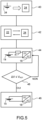
Fig.5 ] lafigure 5 représente un exemple d'organigramme de fonctionnement d'un procédé de l'invention.
- [
Fig.1 ] therefigure 1 represents, in the context of the invention, an electric vehicle connected to a charging terminal; - [
Fig.2 ] therefigure 2 represents an example of a connector allowing the vehicle and the charging station to be connected; - [
Fig.3 ] thereFigure 3 represents part of the electrical diagram of the vehicle and the charging station; - [
Fig.4 ] thereFigure 4 represents another part of the electrical diagram of the vehicle and the charging station; - [
Fig.5 ] thereFigure 5 represents an example of an operating flowchart of a method of the invention.
Par souci de clarté, les mêmes éléments porteront les mêmes repères dans les différentes figures.For the sake of clarity, the same elements will carry the same references in the different figures.
La
La
Comme évoqué plus haut, le convertisseur 18 peut être bidirectionnel et autoriser le transfert d'énergie en provenance du véhicule 10 par exemple pour renvoyer de l'énergie vers le réseau 16 en mode V2G. Dans ce mode, le module de pilotage 24 peut être alimenté par le réseau 16 et établir un dialogue avec le module de commande 22 qui, quant à lui, est alimenté par la batterie 14 du véhicule 10.As mentioned above, the
L'invention s'intéresse au cas où le réseau de distribution 16 est absent et où l'on souhaite alimenter des charges raccordées à la borne 12 à partir d'énergie prélevée dans la batterie 14 du véhicule 10. Les charges alimentées par la borne 12 peuvent former un réseau local 26 parfois appelé ilot.The invention concerns the case where the
La
Lorsque la borne 12 recharge la batterie 14 ou en mode V2G, le module de pilotage 24 est alimentée par la borne 12. Cette alimentation peut être une alimentation dédiée ou utiliser le convertisseur 18. En mode V2H, aucune alimentation n'est disponible dans la borne 12 et le véhicule 10 s'y substitue pour alimenter le module de pilotage 24 au travers du câble 20 et, dans l'exemple représenté, par la borne CP. A cet effet, le véhicule 10 comprend une alimentation basse tension 34 et des moyens de raccordement, formés ici par un interrupteur S3, de l'alimentation basse tension 34 à la borne CP. Côté borne 12, un interrupteur S6 permet de connecter la borne CP au module de pilotage 24.When terminal 12 recharges
Lorsque la borne 12 est alimentée par le réseau de distribution 16, une source de tension 32 de la borne 12 est utilisée pour émettre des signaux vers la borne CP. Dans le véhicule 10, ces signaux sont transmis au module de commande 22 par l'intermédiaire d'une diode D, et d'un pont diviseur formé par des résistances R2 et R3. La résistance R2 peut être activée par l'interrupteur S2. Lorsque la borne 12 est alimentée par le réseau de distribution 16. La borne CP est directement reliée à l'anode de la diode D. Cette liaison directe peut, dans le cadre de l'invention, être ouverte. Plus précisément, un interrupteur S4 permet d'interrompre la liaison directe afin de reproduire les signaux provenant de la borne 12 et interrompus lors de l'arrêt de la source de tension 32 en mode V2H. Plus précisément, une résistance de polarisation Rpb est reliée en série entre la source de tension 32 et la borne CP. Lors de l'arrêt de la source de tension 32 en mode V2H, une autre résistance de polarisation Rpv se substitue à la résistance Rpb pour polariser le module de commande 22. La résistance Rpv est de même valeur que la résistance Rpb et est disposée dans le véhicule 10 et plus précisément entre la borne CP et le module de commande 22. La résistance Rpv est disposée en parallèle de l'interrupteur S4. Ainsi pour permettre à la résistance Rpv de participer à la polarisation du module de commande 22, il suffit d'ouvrir l'interrupteur S4. Pour ne pas perturber la polarisation du module de commande 22, lorsque la résistance Rpv est utilisée, un interrupteur S5 peut être disposé dans la borne 12 de façon à de déconnecter la résistance Rpb de la borne CP.When terminal 12 is powered by the
Par polarisation du module de commande on entend la mise sous tension du module 22 avec une tension lui permettant de détecter l'état du système. Le module 22 va en effet recevoir une tension différente en fonction de la position des différents interrupteurs et donc pourra détecter l'état du système. La commande du module 22 dépend de la tension reçue. Ici la résistance de polarisation Rpv permet au module de commande 22 de détecter, avec une modulation à 100%, le mode V2H tout en respectant le protocole du standard combo CCS.By polarization of the control module we mean powering up the
De façon plus générale, les deux résistances Rpv et Rpb peuvent être des impédances (résistance à laquelle est ajouté une capacité et/ou une inductance en cas de besoin) remplissant une fonction semblable vis-à-vis du module de commande 22 du véhicule 10 ou du module de module de pilotage 24 en combinaison avec la source de tension 32 avec une modulation à 100% de la borne 12 pour l'impédance Rpb et en combinaison avec l'alimentation basse tension 34 du véhicule 10 pour l'impédance Rpv.More generally, the two resistances Rpv and Rpb can be impedances (resistance to which a capacitance and/or an inductance is added if necessary) fulfilling a similar function with respect to the
La source de tension 32 peut être une source de tension continue dont on module la largeur d'impulsion en fonction du type d'informations transmises de la borne 12 vers le module de commande 22 lorsque la borne 12 recharge la batterie 14 du véhicule 10 ou en mode V2G. En mode V2H, dans le cadre de l'invention, la borne CP est utilisée pour alimenter le module de pilotage 24. La tension délivrée par l'alimentation 34 est continue. En d'autres termes, la modulation présente sur la borne CP est à 100%. Cependant une modulation à 100% est interprétée, dans le standard Combo CCS, comme une demande d'arrêt d'urgence de la charge de la batterie 14. Le mode V2H est initié par le véhicule 10 et le module de commande 22 du véhicule est configuré pour ne pas attendre autre chose que cette modulation à 100% et pour ne pas l'interpréter comme une demande d'arrêt d'urgence. Coté borne 12, une fois le module de pilotage 24 alimenté, un dialogue peut s'établir avec le module de commande 22 du véhicule 10, le véhicule10 étant maître dans ce dialogue. Le module de commande 22 du véhicule 10 peut notamment demander à la borne 12 d'interrompre le mode V2H avec une consigne particulière différente d'une modulation à 100% de l'alimentation 34.The
Une fois le dialogue établi entre le module de pilotage 24 de la borne 12 et le module de commande 22 du véhicule 10, il est possible de débuter le transfert d'énergie de la batterie 14 du véhicule 10 vers la borne 12. Ce transfert d'énergie peut être réalisé en deux étapes s'appuyant sur une structure illustrée sur la
Sur la
Après établissement de l'alimentation du module de pilotage 24 de la borne 12 par le véhicule 10, il est possible d'enclencher directement le transfert d'énergie de la batterie 14 vers la borne 12. A cet effet, la liaison entre la batterie 14 et le convertisseur 18 au travers de la borne DC+ comprend un contacteur S8 en série avec le conducteur transitant par la borne DC+. Le contacteur S8 est par exemple situé dans le véhicule 10 et est piloté par le module de commande 22. Cet enclenchement peut se faire sans restriction. Cependant, le réglage de la tension d'entrée du convertisseur 18 peut ne pas être optimal et générer un appel de courant important sur le conducteur transitant par la borne DC+. Cet appel de courant peut endommager la batterie 14 et le contacteur S8. Pour limiter cet appel de courant, il est avantageux de commencer par une étape de pré-charge à intensité limitée. Cette étape est par exemple réalisée au moyen d'une résistance de puissance R disposée en série avec le contacteur S8, par exemple dans le véhicule 10. A titre d'exemple, pour une batterie de 400V de tension continue, la valeur de la résistance R peut être de l'ordre de 100 Ohms. A la fermeture du contacteur S8, même si le convertisseur 18 est équivalent à un court-circuit entre les bornes DC+ et DC-, le courant est ainsi limité à 4 Ampères. La limitation du courant permet cependant au convertisseur 18 de débuter son fonctionnement, notamment en augmentant sa tension d'entrée jusqu'à atteindre une tension voisine de celle délivrée par la batterie 14. Plus précisément, l'étape de pré-charge se poursuit tant que la différence de tension entre la batterie 14 et le convertisseur 18 est supérieure à une valeur donnée. Lorsque la différence de tension devient inférieure ou égale à la valeur donnée, il est possible de se passer de la limitation en courant. A cet effet, le véhicule 10 comprend un autre contacteur S9 disposé en parallèle de la résistance R et permettant de la court-circuiter. Le contacteur S9 est piloté par le module de commande 22. Pour le pilotage du contacteur S9, le module de commande 22 échange avec le module pilotage 24 pour comparer la tension de la batterie 14 et la tension d'entrée du convertisseur 18, coté continu.After establishment of the power supply to the
la
Claims (6)
- Electric vehicle that is intended to exchange power with a station (12), the vehicle (10) comprising a control module (22) that is intended to communicate through a cable (20) with a drive module (24) for driving a power converter (18) of the station (12), characterized in that the vehicle (10) further comprises a low-voltage power supply (34), connection means (S3) for connecting the low-voltage power supply (34) to the cable (20) so as to supply power to the drive module (24) of the station (12), and an impedance (Rpv) that has substantially the same value as an impedance (Rpb) of the station (12) through which the drive module (24) of the station (12) may be supplied with power by a voltage source (32) of the station (12), the impedance (Rpv) of the vehicle (10) being arranged between the control module (22) and the cable (20) and in that it comprises a switch (S4) that allows the impedance (Rpv) of the vehicle (10) to be short-circuited.
- Station that is intended to exchange power with an electric vehicle (10), the station (12) comprising a power converter (18) and a drive module (24) for driving the power converter (18), the drive module (24) being intended to communicate through a cable (20) with a control module (22) of the vehicle (10), characterized in that the station (12) further comprises means (S6) for receiving a voltage originating from a low-voltage power supply (34) of the vehicle (10) through the cable (20) so as to supply power to the drive module (24), and a voltage source (32) that is able to generate signals intended for the control module (22) of the vehicle (10) through an impedance (Rpb) of the station (12), the cable (20) and an impedance (Rpv) of the vehicle (10) that may be short-circuited by a switch (S4) of the vehicle (10) .
- Station according to Claim 2, characterized in that the means for receiving a power supply voltage comprise a switch (S5) that allows the voltage source (32) to be disconnected.
- Vehicle according to Claim 1, which is intended to exchange power with a station (12) according to either of Claims 2 and 3, characterized in that the vehicle (10) further comprises temporary means (R, S9) for limiting the power that is transferred between it and the station (12).
- Method that implements a vehicle (10) according to either of Claims 1 and 4 and a station (12) according to Claim 2, which are intended to exchange power, characterized in that it consists in concatenating the following operations:-supplying power (40) to the drive module (24) of the station (12) by means of the low-voltage power supply (34) of the vehicle (10),- starting a data exchange (42) through the cable (20) in order to drive the power converter (18) so as to receive power from the vehicle (10),- transferring power (44, 46) from the vehicle (10) to the station (12).
- Method that implements a vehicle (10) according to Claim 1, wherein transferring power from the vehicle (10) to the station comprises two consecutive steps:- a step of pre-charging (44) at limited current as long as the voltage difference between the battery (14) and the converter (18) is greater than a given value,- a step of transferring power without limitations on current (46) as soon as the voltage difference between the battery (14) and the converter (18) is less than or equal to the given value.
Applications Claiming Priority (2)
| Application Number | Priority Date | Filing Date | Title |
|---|---|---|---|
| FR1914975A FR3105119B1 (en) | 2019-12-19 | 2019-12-19 | Electric vehicle, charging station and energy exchange method between the vehicle and the terminal |
| PCT/EP2020/083882 WO2021121923A1 (en) | 2019-12-19 | 2020-11-30 | Electric vehicle, charging station and method of exchanging power between the vehicle and the station |
Publications (2)
| Publication Number | Publication Date |
|---|---|
| EP4077034A1 EP4077034A1 (en) | 2022-10-26 |
| EP4077034B1 true EP4077034B1 (en) | 2024-01-03 |
Family
ID=70613964
Family Applications (1)
| Application Number | Title | Priority Date | Filing Date |
|---|---|---|---|
| EP20815802.2A Active EP4077034B1 (en) | 2019-12-19 | 2020-11-30 | Electric vehicle, charging station and method of exchanging power between the vehicle and the station |
Country Status (5)
| Country | Link |
|---|---|
| EP (1) | EP4077034B1 (en) |
| KR (1) | KR20220111702A (en) |
| CN (1) | CN115279619A (en) |
| FR (1) | FR3105119B1 (en) |
| WO (1) | WO2021121923A1 (en) |
Family Cites Families (3)
| Publication number | Priority date | Publication date | Assignee | Title |
|---|---|---|---|---|
| JP5234159B2 (en) * | 2011-10-31 | 2013-07-10 | トヨタ自動車株式会社 | A vehicle including a power storage unit capable of discharging (power feeding) to an external load, a discharge system including the vehicle and a power cable, a discharge control method for the power storage unit, and a device outside the vehicle used in the discharge system. |
| JP5918330B2 (en) * | 2014-10-01 | 2016-05-18 | 株式会社東光高岳 | Electric mobile charging device |
| KR101876056B1 (en) * | 2016-09-12 | 2018-07-06 | 현대자동차주식회사 | Charging method for electric vehicle |
-
2019
- 2019-12-19 FR FR1914975A patent/FR3105119B1/en active Active
-
2020
- 2020-11-30 KR KR1020227023899A patent/KR20220111702A/en active Search and Examination
- 2020-11-30 CN CN202080090341.6A patent/CN115279619A/en active Pending
- 2020-11-30 EP EP20815802.2A patent/EP4077034B1/en active Active
- 2020-11-30 WO PCT/EP2020/083882 patent/WO2021121923A1/en unknown
Also Published As
| Publication number | Publication date |
|---|---|
| KR20220111702A (en) | 2022-08-09 |
| WO2021121923A1 (en) | 2021-06-24 |
| FR3105119A1 (en) | 2021-06-25 |
| CN115279619A (en) | 2022-11-01 |
| EP4077034A1 (en) | 2022-10-26 |
| FR3105119B1 (en) | 2021-11-19 |
Similar Documents
| Publication | Publication Date | Title |
|---|---|---|
| EP3065969B1 (en) | Compact charging device for electric vehicle | |
| EP3066739B1 (en) | Method of charging from electric vehicle to electric vehicle | |
| CN107082028B (en) | Battery charging system and charging method using the same | |
| EP2915244B1 (en) | Charge transfer method and related electric device | |
| EP3607644B1 (en) | Method for controlling a charging device on board an electric or hybrid vehicle | |
| EP4077034B1 (en) | Electric vehicle, charging station and method of exchanging power between the vehicle and the station | |
| EP2820739A1 (en) | Electric circuit for charging at least one electrical energy storage unit by means of an electrical network | |
| FR3027854B1 (en) | ELECTRICAL CONNECTION CABLE FOR CHARGING AN ENERGY ACCUMULATOR OF A MOTOR VEHICLE | |
| EP3179597B1 (en) | Improved device for supplying single-phase and three-phase electricity | |
| EP4038716B1 (en) | Electric charger for aeronautical maintenance equipment | |
| CN112477640B (en) | Converter | |
| FR3011400A1 (en) | SYSTEM AND METHOD FOR CHARGING A TRACTION BATTERY CURRENT CALLING CURRENT CAPACITIES PARASITES | |
| WO2019110297A1 (en) | Dc-dc converter with pre-charging of a first electrical grid from a second electrical grid | |
| WO2015145010A1 (en) | Vehicle including onboard apparatus, particularly cryogenic apparatus, and connection device for supplying electrical power to said apparatus | |
| WO2023209296A1 (en) | Electric charging assembly for an electric motor vehicle | |
| WO2024047293A1 (en) | Motor vehicle comprising a charging assembly for charging an electric traction battery | |
| FR3138363A1 (en) | Electric charging system for a battery vehicle | |
| FR3074983A1 (en) | CONTINUOUS-CONTINUOUS CONVERTER FOR AN ELECTRIC OR HYBRID VEHICLE WITH RECOVERY OF SECONDARY LOSSES |
Legal Events
| Date | Code | Title | Description |
|---|---|---|---|
| STAA | Information on the status of an ep patent application or granted ep patent |
Free format text: STATUS: UNKNOWN |
|
| STAA | Information on the status of an ep patent application or granted ep patent |
Free format text: STATUS: THE INTERNATIONAL PUBLICATION HAS BEEN MADE |
|
| PUAI | Public reference made under article 153(3) epc to a published international application that has entered the european phase |
Free format text: ORIGINAL CODE: 0009012 |
|
| STAA | Information on the status of an ep patent application or granted ep patent |
Free format text: STATUS: REQUEST FOR EXAMINATION WAS MADE |
|
| 17P | Request for examination filed |
Effective date: 20220607 |
|
| AK | Designated contracting states |
Kind code of ref document: A1 Designated state(s): AL AT BE BG CH CY CZ DE DK EE ES FI FR GB GR HR HU IE IS IT LI LT LU LV MC MK MT NL NO PL PT RO RS SE SI SK SM TR |
|
| DAV | Request for validation of the european patent (deleted) | ||
| DAX | Request for extension of the european patent (deleted) | ||
| GRAP | Despatch of communication of intention to grant a patent |
Free format text: ORIGINAL CODE: EPIDOSNIGR1 |
|
| STAA | Information on the status of an ep patent application or granted ep patent |
Free format text: STATUS: GRANT OF PATENT IS INTENDED |
|
| INTG | Intention to grant announced |
Effective date: 20230721 |
|
| GRAS | Grant fee paid |
Free format text: ORIGINAL CODE: EPIDOSNIGR3 |
|
| GRAA | (expected) grant |
Free format text: ORIGINAL CODE: 0009210 |
|
| STAA | Information on the status of an ep patent application or granted ep patent |
Free format text: STATUS: THE PATENT HAS BEEN GRANTED |
|
| AK | Designated contracting states |
Kind code of ref document: B1 Designated state(s): AL AT BE BG CH CY CZ DE DK EE ES FI FR GB GR HR HU IE IS IT LI LT LU LV MC MK MT NL NO PL PT RO RS SE SI SK SM TR |
|
| REG | Reference to a national code |
Ref country code: GB Ref legal event code: FG4D Free format text: NOT ENGLISH |
|
| REG | Reference to a national code |
Ref country code: CH Ref legal event code: EP |
|
| REG | Reference to a national code |
Ref country code: DE Ref legal event code: R096 Ref document number: 602020023955 Country of ref document: DE |
|
| REG | Reference to a national code |
Ref country code: IE Ref legal event code: FG4D Free format text: LANGUAGE OF EP DOCUMENT: FRENCH |
|
| RAP2 | Party data changed (patent owner data changed or rights of a patent transferred) |
Owner name: NISSAN MOTOR CO., LTD. Owner name: AMPERE SAS |
|
| REG | Reference to a national code |
Ref country code: LT Ref legal event code: MG9D |