EP4076594B1 - Arzneimittelabgabevorrichtung zur abgabe einer vorgegebenen festen dosis - Google Patents
Arzneimittelabgabevorrichtung zur abgabe einer vorgegebenen festen dosis Download PDFInfo
- Publication number
- EP4076594B1 EP4076594B1 EP20817407.8A EP20817407A EP4076594B1 EP 4076594 B1 EP4076594 B1 EP 4076594B1 EP 20817407 A EP20817407 A EP 20817407A EP 4076594 B1 EP4076594 B1 EP 4076594B1
- Authority
- EP
- European Patent Office
- Prior art keywords
- drive tube
- axial
- drive
- shield
- housing
- Prior art date
- Legal status (The legal status is an assumption and is not a legal conclusion. Google has not performed a legal analysis and makes no representation as to the accuracy of the status listed.)
- Active
Links
Images













Classifications
-
- A—HUMAN NECESSITIES
- A61—MEDICAL OR VETERINARY SCIENCE; HYGIENE
- A61M—DEVICES FOR INTRODUCING MEDIA INTO, OR ONTO, THE BODY; DEVICES FOR TRANSDUCING BODY MEDIA OR FOR TAKING MEDIA FROM THE BODY; DEVICES FOR PRODUCING OR ENDING SLEEP OR STUPOR
- A61M5/00—Devices for bringing media into the body in a subcutaneous, intra-vascular or intramuscular way; Accessories therefor, e.g. filling or cleaning devices, arm-rests
- A61M5/178—Syringes
- A61M5/31—Details
- A61M5/315—Pistons; Piston-rods; Guiding, blocking or restricting the movement of the rod or piston; Appliances on the rod for facilitating dosing ; Dosing mechanisms
- A61M5/31565—Administration mechanisms, i.e. constructional features, modes of administering a dose
- A61M5/3159—Dose expelling manners
- A61M5/31593—Multi-dose, i.e. individually set dose repeatedly administered from the same medicament reservoir
- A61M5/31595—Pre-defined multi-dose administration by repeated overcoming of means blocking the free advancing movement of piston rod, e.g. by tearing or de-blocking
-
- A—HUMAN NECESSITIES
- A61—MEDICAL OR VETERINARY SCIENCE; HYGIENE
- A61M—DEVICES FOR INTRODUCING MEDIA INTO, OR ONTO, THE BODY; DEVICES FOR TRANSDUCING BODY MEDIA OR FOR TAKING MEDIA FROM THE BODY; DEVICES FOR PRODUCING OR ENDING SLEEP OR STUPOR
- A61M5/00—Devices for bringing media into the body in a subcutaneous, intra-vascular or intramuscular way; Accessories therefor, e.g. filling or cleaning devices, arm-rests
- A61M5/178—Syringes
- A61M5/31—Details
- A61M5/315—Pistons; Piston-rods; Guiding, blocking or restricting the movement of the rod or piston; Appliances on the rod for facilitating dosing ; Dosing mechanisms
- A61M5/31533—Dosing mechanisms, i.e. setting a dose
- A61M5/31535—Means improving security or handling thereof, e.g. blocking means, means preventing insufficient dosing, means allowing correction of overset dose
- A61M5/31536—Blocking means to immobilize a selected dose, e.g. to administer equal doses
-
- A—HUMAN NECESSITIES
- A61—MEDICAL OR VETERINARY SCIENCE; HYGIENE
- A61M—DEVICES FOR INTRODUCING MEDIA INTO, OR ONTO, THE BODY; DEVICES FOR TRANSDUCING BODY MEDIA OR FOR TAKING MEDIA FROM THE BODY; DEVICES FOR PRODUCING OR ENDING SLEEP OR STUPOR
- A61M5/00—Devices for bringing media into the body in a subcutaneous, intra-vascular or intramuscular way; Accessories therefor, e.g. filling or cleaning devices, arm-rests
- A61M5/178—Syringes
- A61M5/31—Details
- A61M5/315—Pistons; Piston-rods; Guiding, blocking or restricting the movement of the rod or piston; Appliances on the rod for facilitating dosing ; Dosing mechanisms
- A61M5/31565—Administration mechanisms, i.e. constructional features, modes of administering a dose
- A61M5/31576—Constructional features or modes of drive mechanisms for piston rods
- A61M5/31583—Constructional features or modes of drive mechanisms for piston rods based on rotational translation, i.e. movement of piston rod is caused by relative rotation between the user activated actuator and the piston rod
-
- A—HUMAN NECESSITIES
- A61—MEDICAL OR VETERINARY SCIENCE; HYGIENE
- A61M—DEVICES FOR INTRODUCING MEDIA INTO, OR ONTO, THE BODY; DEVICES FOR TRANSDUCING BODY MEDIA OR FOR TAKING MEDIA FROM THE BODY; DEVICES FOR PRODUCING OR ENDING SLEEP OR STUPOR
- A61M5/00—Devices for bringing media into the body in a subcutaneous, intra-vascular or intramuscular way; Accessories therefor, e.g. filling or cleaning devices, arm-rests
- A61M5/178—Syringes
- A61M5/31—Details
- A61M5/315—Pistons; Piston-rods; Guiding, blocking or restricting the movement of the rod or piston; Appliances on the rod for facilitating dosing ; Dosing mechanisms
- A61M5/31565—Administration mechanisms, i.e. constructional features, modes of administering a dose
- A61M5/3159—Dose expelling manners
- A61M5/31593—Multi-dose, i.e. individually set dose repeatedly administered from the same medicament reservoir
-
- A—HUMAN NECESSITIES
- A61—MEDICAL OR VETERINARY SCIENCE; HYGIENE
- A61M—DEVICES FOR INTRODUCING MEDIA INTO, OR ONTO, THE BODY; DEVICES FOR TRANSDUCING BODY MEDIA OR FOR TAKING MEDIA FROM THE BODY; DEVICES FOR PRODUCING OR ENDING SLEEP OR STUPOR
- A61M5/00—Devices for bringing media into the body in a subcutaneous, intra-vascular or intramuscular way; Accessories therefor, e.g. filling or cleaning devices, arm-rests
- A61M5/178—Syringes
- A61M5/31—Details
- A61M5/32—Needles; Details of needles pertaining to their connection with syringe or hub; Accessories for bringing the needle into, or holding the needle on, the body; Devices for protection of needles
- A61M5/3202—Devices for protection of the needle before use, e.g. caps
Definitions
- the present invention relates to a drug delivery device for delivering a fixed dose.
- the present invention especially relates to such drug delivery device comprising a drive mechanism with helical and axial guiding portions.
- Drug delivery devices for self-administration of different liquid drug formulation presently exist in various shapes and sizes. Some are adapted for connecting to an infusion set, and some are connectable or integrated with an injection needle. The latter type is referred to as injection devices. Some are durable devices comprising a cartridge with a drug reservoir, wherein the cartridge can be changed. Others are disposable devices that are discarded when the cartridge is empty. Disposable devices can be either multi-dose devices, in which the user can set the desired dose size prior to each injection, or single dose devices, capable of administering only a single dose of a given size. The latter exists with so-called “Shield activation", where the cannula is covered by a shield in the front of the device that releases the dose when pressed. The cannula is then exposed only to enter the skin, when the user presses the device against the skin, and thereby depresses the shield, and releases the dose. These injection devices are disposed after a single injection.
- the device itself is responsible for a considerably part of the costs of the unit, not to mention the amount of materials used and thus necessary to dispose. It would therefore be desirable to make a fixed dose device capable of delivering multiple doses of a fixed volume.
- the motor In existing multi-dose devices, the motor consists of a spring being wound up when adjusting the dose.
- One solution is to make a normal multi-dose device where the maximum dose size is limited, so it is only possible to dial up to the fixed dose size. This would however introduce a risk that the user does not dial up sufficiently and thus gets a smaller dose than expected, this problem has been solved in WO2020089167 filed by No-vo Nordisk, wherein a ratchet tube is locked to the housing until the full dose has been set and the drive mechanism has been released.
- the injection device comprises a spring 80, 144 to urge the dose tracker in the proximal direction.
- the injection device further comprises an interlock 84, 184, 284, 584 to lock the dose tracker in the initial position (i), and a release member 100, 101, 190, 290, 590 to release the interlock 84, 184, 284.
- the disclosure relates to an injection device for delivering a defined number of equal doses of a fluid substance.
- the disclosed injection device comprises a housing 1 with an arming mechanism and a dose delivery mechanism arranged along the longitudinal axis of the housing.
- the housing is coupled to an enclosure 3 for receiving a reservoir with the fluid substance.
- the arming mechanism comprises a setting sleeve 5, which is axially non-displaceable.
- the arming mechanism is rotatable about the axis of the housing in two opposite directions by a defined setting angle (a).
- a further object is to provide such a drug delivery device comprising a drive mechanism with helical and axial guiding portions.
- the drive mechanism comprises helical and axial guide portions to provide a fixed dose upon activation.
- the guide structure of the housing assembly is a closed guide providing a work cycle for the drive tube, and wherein a starting position and an end of dose position of the drive tube is the same.
- the drive mechanism is adapted for providing a plurality of fixed doses using the same work cycle.
- the housing assembly further comprises an inner tread, wherein the piston rod comprises an outer thread engaging the inner thread of the housing assembly.
- the drive tube is axially splined to the piston rod, whereby relative axial movement is allowed and relative rotation is prevented, and whereby the piston rod (109, 209) is advanced in response to rotation of the drive tube.
- a spline connection may comprise a key fitting in a key way.
- the drive mechanism further comprises a motor mechanism for imparting rotation of the drive tube for delivering a dose, in response to activation of the drive mechanism, wherein the drive tube is axially splined to the piston rod, whereby the drive tube is axially movable and rotationally locked relative to the piston rod, wherein drive mechanism further comprises a return mechanism for moving the drive tube in an axial direction, and thereby returning the drive tube after activation.
- the triggering mechanism comprises a movably arranged connector, wherein the connector comprises an activation tab, and wherein the activation tab is adapted for engaging a surface portion of the drive tube, in response to moving the connector in an axial direction, whereby the connector is operatively connected to the drive mechanism and adapted for triggering the drive mechanism, wherein the surface portion is oriented in a direction towards the activation tab.
- the activation tab can abut the surface portion of the drive tube during activation.
- the stationary state comprises: that the drive tube can be arranged in a home position, wherein the drive tube can be arranged in a first axial position, wherein the drive tube is allowed to move in one axial direction and blocked by the housing in the other axial direction, and arranged in a first angular position, wherein the drive tube is rotationally blocked by the housing in one direction and restricted in the other rotational direction by the drive mechanism, wherein the guide structure of the drive tube abuts the axial portion of the housing assembly and the helical portion of the guide structure of the housing assembly; wherein the dosing state comprises:
- the connector is adapted to move the drive tube between the first axial and the second axial position, whereby the position of the drive tube (180, 280) is changed from the home position to the first dosing position, in response to moving the connector from a first axial to a second axial position, and wherein the drive mechanism is adapted to rotate the drive tube, and thereby change the position of the drive tube from the first dosing position, to the second dosing position and to the home position, in response to activation of the drive mechanism by setting the drive tube in the first dosing position.
- the motor mechanism comprises a compression drive spring
- the activation tab comprises a helical surface portion
- the engageable surface portion of the drive tube for activating the drive tube comprises a helical surface portion
- the activation tab is adapted to impart an initial rotation of the drive tube in the dosing direction, in response to engaging the tab and moving the drive tube against the biasing force of the compression spring and between the distal and the proximal position
- the helical portion of the housing assembly and the compression spring is adapted to provide further rotation of the drive tube, in response to the initial rotation, whereby a complete fixed dose can be delivered.
- the injection device is adapted for providing a plurality of predefined fixed doses
- an injection device comprising a reusable integrated needle cannula with a cleaning chamber.
- a needle magazine as described in EP20157959.6 titled an injection device with integrated needles could be integrated instead one single re-usable needle and filed by Novo Nordisk.
- the injection device comprises a housing assembly, providing a rigid frame with guides and connectors for guiding and connecting the other components of the device.
- the housing assembly comprises the housing insert portion 160, the tubular elongate housing structure 140, the cartridge holder 130 and the spring base 165. After final assembly these structures are fixedly connected, and the housing assembly can provide a frame of reference for describing the relative movement and position of the other structures.
- the elongate housing structure 140 comprises an internal thread for engaging an outer thread of the piston rod.
- the internal thread may be provided in the form of an integral nut member, which is fixed to the housing structure 140 both rotationally and axially.
- the nut member is an integral part of the housing structure 140.
- the injection device further comprises a needle shield assembly comprising the shield tip 119 and the elongate shield structure 110.
- the elongate shield structure 110 comprises a window 111 for inspection of the drug, the elongate shield can be arranged in a first position of overlapping with the cartridge holder window 131, and in a second position with no overlap, wherein a solid portion of the elongate shield structure covers the window 131 in the second position.
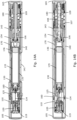
- the cartridge holder 130 is adapted for receiving the cartridge 135.
- the cartridge holder comprises a window 131 for inspecting the drug in the cartridge 135.
- Figure 1B show in profile the cartridge holder 130 comprising an axial rib 132 for axially guiding the needle hub, a flexible arm for snapping to a neck portion 137 ( fig. 1A ) of the cartridge and a proximally extending tab 130.1 for aligning and positioning the cartridge when inserted into the housing during assembly.
- a circumferentially extending flange 134 fig. 1A ), providing a small axial clearance to the distal end surface of the cartridge, after assembly and in an initial out-of-pack state.
- the elongate cartridge 135 comprises a distal end 135a sealed by a pierceable septum and an open proximal end 135 closed by a piston.
- the piston is not shown on figure 1 .
- the cartridge comprises a reservoir containing the plurality of fixed doses of a medicament.
- a septum capped on by a cap.
- the cap and a main portion of the reservoir is separated by the neck portion 137.
- the injection device further comprises a needle assembly comprising a needle hub 125 and a reusable needle cannula 124.
- the cannula comprises a proximal end for piercing the pierceable septum and for establishing fluid communication with the reservoir, and a distal end for insertion into the skin of a subject or user of the device.
- the cap 105 is adapted for releasable mounting to the housing insert portion 160.
- the cap comprises an inner surface with a protrusion 105.2 ( Fig 16F ) adapted to be guided by the axial and the circumferential cap mount track 161, which will be described in detail later in the application.
- the protrusion is further adapted to cooperate with a snap lock 161.1 and thereby releasably lock the cap 105 to the inner housing portion 160.
- the cap is adapted to be mounted and demounted by a sequential axial and rotational movement, and thereby provides a bayonet coupling together with the injection device.
- the inner surface of the cap 105 further comprises an axially extending rib 105.1 ( Fig. 16A ) protruding from the inner surface and adapting the cap for transferring a torque to the shield structure 110 through an axially extending rib 116 on the outer surface of the shield, as will be explained later with reference to figure 16A .
- the spring base 165 is fixedly mounted to the housing structure 140 at the proximal end and is adapted to receive and support a compressible torsional drive spring 108.
- the drive spring 108 is pre-strained or winded up and positioned between the spring base and the drive tube 180.
- the drive spring is further adapted to induce a torque on the drive tube, whereby the medicament can be expelled.
- the drive spring comprises torsional sections 108.3, 108.4, wherein the spacing between the coils is relatively small and a compressible section 108.4 adapted to transfer an axial force to the drive tube after compression and during expelling of the medicament.
- the ability to drive the drive tube in an axial direction enables an end of dose mechanism, and to enable a resetting of the drive tube.
- the connector return spring 107 is positioned between the spring base 165 and the connector 170 and is adapted to urge the connector in the distal direction.
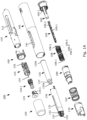
- the injection device comprises a cleaning assembly 120, as illustrated in figure 2B .
- the movable shield structure 110 is fixedly connected to the cleaning assembly 120 through a shield following portion 120.1, and the principles of the cleaning module is disclosed in further details in WO2019/101670 .
- the cleaning assembly 120 comprises a cleaning agent, which keeps the distal end of the needle cannula 124 clean between injections.
- the shield following portion 120.1 of the cleaning module is fixedly connected to the shield tip 119, which again is fixedly connected to the movably arranged elongate needle shield structure 110.
- the shield tip 119 can be click fitted to the needle shield structure 110 via resilient arms 119.1 engaging the elongate shield structure 110, such that the cleaning chamber assembly 120 follows axial and rotational movements of the movably arranged shield structure 110.
- the shield structure 110 which is connected to the cleaning assembly 120 is movably arranged relative to the needle cannula 124, which is fixed to the housing.
- the cleaning assembly 120 preferably contains a chamber with a liquid cleaning agent which in one example can be the same preservative as contained in the liquid drug in the cartridge 135.
- the cleaning agent is the identical same preservative containing pharmaceutical liquid drug as contained in the cartridge 135, which is filled into the chamber of the cleaning module during the initiation of the injection device.
- the cleaning agent is embedded in a porous plug.
- the cleaning agent is embedded in a matrix of a solid plug.
- the shield can be arranged in different positions.
- An initial position defined by an initial angular position and a corresponding initial axial position.
- a locked position defined by a locked angular position and a corresponding locked axial position.
- An unlocked distal position defined by an unlocked angular position and a corresponding distal unlocked axial position.
- the movable shield can be changed by a combined rotational and proximal movement from the initial position to the locked position, wherein the shield is axially locked. In both positions the needle tip is covered by the shield and contained in the cleaning chamber assembly. During use the shield can be further rotated and moved further in the proximal direction to the unlocked distal position, whereby the tip is uncovered. By moving the shield further in the proximal direction the shield uncovers a larger portion of the needle and an injection can be made. After injection the shield is moved back to the locked position, whereby the needle tip is cleaned.
- the needle following portion 120.1 comprises a cleaning chamber housing 121 comprising a distal tubular portion, a middle tubular portion and a proximal tubular portion.
- the portions are integrally connected.
- a cap On the distal end of the distal tubular portion is provided a cap, capping a distal septum onto the cleaning chamber housing.
- a shield tab 121.1 On the outer surface of the middle tubular portion is provided a shield tab 121.1 for snapping to the shield tip 119, and a hub pushing tab 121.2.
- Window W1 of fig. 1C illustrates the same components in grey scale to better illustrate inclined surfaces and void portions.
- a torsion spring in the drive mechanism provides several advantages.
- the inventors of the present invention realized that for an embodiment constructed with a compression spring, the compression spring advances into the cartridge as it releases energy. If the injection device is designed without allowing the compression spring advancing into the cartridge, the overall length of the device will increase. Therefore, in a construction of limited length the diameter of the spring is limited by the diameter of the cartridge.
- the inventors of the present invention found that as a torsional spring does not have to extend into the cartridge in order to limit the overall length of the device. Therefore, the torsional drive spring is not limited by the diameter of the cartridge or the piston rod and is advantageous in a construction of limited length.
- the drive tube can be adapted to provide dose clicks and allows an increase of the number of dose clicks by increasing the diameter. Therefore, the number of dose clicks can be increased without extending the axial length of the device.
- the outer surface of the drive tube comprises a dose click providing structure adapted to provide dose clicks, e.g., a ratchet arm riding over teeth provided on a surrounding structure.
- the ratchet arm is provided on the surrounding structure and the teeth on the drive tube.
- the number of dose clicks can be increased by increasing the radius, but without increasing the length of the spring and thereby the device.
- the length of the compression spring has to be increased.
- the required energy to release a triggering mechanism i.e., the activation energy
- the required energy to release a triggering mechanism is a function of the internal stress of the drive spring. Therefore, activation of the dose engine enabled with a torsional drive spring requires less force than a similar design based on a compression spring.
- an embodiment comprising a drive mechanism based on a torsional drive spring is easier to assemble than an embodiment based on an equivalent compression drive spring. Compared to the compression spring, the torsional spring is relatively short and is thus easier to handle.
- the rotating drive tube is easily adapted to function with an electronic dose capturing device, which register a rotating structure during dosing, as described in WO 2019/110494 , titled "Drug delivery system with multipolar magnet and sensor system”.
- a snap lock 161c.1 At the first end of the circumferential track is positioned a snap lock 161c.1, and the second end is connected to the proximal end of the axially extending track 161c.2, whereby the track portions form a track for a bayonet coupling for cooperating with an inner protrusion of the cap 105.
- a rotational stop 161c.4 At the second end of the track 161c is also provided a rotational stop 161c.4.
- the housing insert portion 160 further comprises an axially extending slit 163c, on an inner surface for cooperating with an axially extending rib 116c on an outer surface of the shield (see figure 10A ), as will be explained later.
- the inner housing portion 160 further comprises a proximal guide 162 for guiding the shield 110.
- the illustrated proximal guide 162d extends in the circumferential direction, and in a counter clockwise direction the guide comprises a helical portion 162d.1, a transverse portion 162d.2 with zero pitch and an axial portion 162d.3.
- a thread coupling can be used to a bayonet coupling.
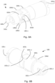
- Figure 10A and 10B show perspective views of the cylindrical elongate shield structure 110 to be arranged inside the tubular housing 140.
- the elongate shield structure 110 comprises a tubular portion comprising an outer surface with an outer diameter and an inner surface with an inner diameter.
- the axially extending rib 116c is arranged at the distal end ant protrudes from the outer surface.
- the rib is adapted for cooperating with the internal rib of the cap 105, and for cooperating with the slit 163 on the inner surface of the housing insert portion 165.
- the shield structure 110 further comprises a step-wise helical guide 112 arranged on the outer surface and adapted for cooperating with the proximal guide 162 of the housing insert portion and the distal guide 142 of the housing.
- the step-wise helical guide 112 is provided in the annular space between the outer surface of the tubular portion of the shield structure 110 and the inner surface of the outer tubular portion 143 of the housing.
- the step-wise helical guide comprises a continuous protruding structure extending in the axial and circumferential direction and comprises a proximal transverse protruding portion, a proximal left-handed helical protruding portion, a middle transverse protruding portion, a distal left-handed helical protruding portion, a distal transverse protruding portion.
- the continuous protruding structure comprises a plurality of axially and circumferentially oriented surface portions providing the guide surfaces (a circumferential surface or a circumferentially oriented surface means that at least a component of the normal vector is oriented in the circumferential direction).
- the surface portions can be seen on figure 10 and are referred to with the following terms and reference numbers.
- the guide portions 112.2, 112.4, 112.6, 112.8 and 112.10 provides a distal face of the stepwise helical guide 112, and the guide portions 112.3, 112.5, 112.7, 112.9 and 112.11 provides a proximal face.
- the elongate shield structure 110 further comprises a proximal guide 114 positioned at the proximal end of the shield structure 110.
- a proximal guide 114 positioned at the proximal end of the shield structure 110.
- the proximal guide 114 is adapted to cooperate with the connector 170 and the middle guide 144 of the housing.
- the proximal guide 114 extends in the axial and circumferential direction and comprises a first left-handed helical portion 114.1, a first right-handed helical portion 114.2, a second right-handed helical portion 114.3, a second left-handed helical portion 114.4, a first axial portion 114.5, a first transverse portion 114.6, a second axial portion 114.7, a third axial portion 114.8 and a second transverse portion 114.9.
- the guide portions 114.1-114.9 are all surface portions and the guide portions 114.1, 114.2, 114.3, 114.4 and 114.9 provides a proximal face of the proximal guide 114, and the surface portion 114.6 provides a distal face, i.e., viewable from proximal and distal position, respectively.
- the guide portions 114.1, 114.2, 114.3 and 114.4 of the proximal face are adapted for cooperating with the connector during activation operations.
- the guide portion 114.6 of the distal face of the proximal guide is adapted for cooperating with the connector during dosing, in response to premature release of pressure on the shield, which will be explained in detail later in the application.
- the third axial portion 114.8 is adapted for cooperating with the middle guide 144 of the housing and provides a rotational stop, preventing further counterclockwise rotation of the shield, with respect to the housing and during dosing. Similar, the second transverse portion 114.9 provides an axial stop cooperating with the middle guide 144 and prevents further proximal movement of the shield during dosing.
- the proximal guide 114 comprises a locking structure 115 comprising the guide portions 114.4 and 114.5, in the illustrated embodiment the locking structure 115 is a part of a hook resembling structure. As will be explained in detail later, the locking structure 115 is adapted for releasably locking to a corresponding hook resembling structure of the connector 170 during dosing.
- the shield further comprises a click-arm 113, with an axial surface portion 113.1 providing a rotational stop.
- the click-arm is radially compressed by an inner surface of the housing insert portion 160.
- Figure 11A and 11B show perspective views of the connector 170 to be arranged inside the tubular housing 140 and between the elongate shield structure 110 and the drive tube.
- the connector 170 is adapted for establishing a connection between the shield and the drive tube, and for activating the drive tube 180.
- the connector 170 is further operatively connected in a an automatic relock mechanism adapted for automatically relocking the shield at the end of a dose.
- the connector 170 comprises a distal guide 172 adapted to cooperate with the proximal guide 114 of the shield.
- the distal guide 172 is extending in the circumferential and the axial direction and comprises a left-handed helical portion 172.1, a right-handed helical portion 172.2, a first axial portion 172.3, a transverse portion 172.4 and a second axial portion 172.5.
- the guide portions 172.1-114.5 are all surface portions and the guide portions 114.1 and 114.2 provides a distal face of the distal guide 172, and the surface portion 172.4 provides a proximal face.
- the guide portions 172.1 and 172.2 of the distal face are adapted for cooperating with the proximal guide of the shield during activation operations.
- the guide portion 172.4 of the proximal face is adapted for cooperating with the guide portion 114.6 of the proximal guide of the shield during dosing, in response to premature release of pressure on the shield, which will be explained in detail later in the application.
- the return spring 107 urges the connector in the distal direction. Therefore, the left-handed helical portion urges the connector in a clockwise direction and the shield in a counterclockwise direction, in response to establishing an engagement between the left-handed helical portion 172.1 and the first left handed helical portion 114.1 of the proximal guide of the shield, or in response to establishing an engagement between the left-handed helical portion 172.1 and the second left handed helical portion 114.1 of the proximal guide of the shield.
- the distal guide 172 comprises a locking structure 171 comprising the left-handed helical portion 172.1 and the first axial portion 172.3.
- the locking structure 171 is a part of the hook resembling structure adapted for releasably locking to the corresponding hook resembling structure of the proximal guide 114 of the shield.
- the releasable lock between the hook resembling structures is established, in response to the second left-handed helical portion 114.4 of the locking structure 115 of the shield is brought into abutment with the left-handed helical portion 172.1 of the locking structure 171 of the connector under axial compression from the return spring 107.
- the shield is urged in the counterclockwise direction and the connector is urged toward the counterclockwise direction, and abutment is established between the first axial portion 172.3 of the connector and the first axial portion 114.5 of the shield.
- the friction established in the abutment between the two left-handed helical portions 114.4 and 172.1 has to be exceeded, in response to a counter clockwise rotation of the connector.
- the first tubular portion 185 is also the distal tubular portion and is arranged inside the inner tubular portion 154 of the housing.
- the distal tubular portion comprises an outer tubular portion 185.1 in contact with the inner tubular portion 154.
- the outer tubular portion 185.1 is connected to the second tubular portion 186 and further comprises the axial surface portion 182c adapted for cooperating with the housing during activation and for defining the end of the dose.
- the outer tubular portion 185.1 further comprises a distal helical surface portion 189c adapted for cooperating with a proximal helical surface portion of the inner tubular portion 154 of the housing during dosing (see also figure 8A ).
- Figure 14 illustrates the device 100 in an initiated state, wherein the shield has been rotated to initiate the device.
- the shield has moved proximally in a helical movement together with the needle assembly 120.
- the proximal movement of the shield has induced a proximal movement of the needle hub 125, whereby the needle 124 has established fluid connection with the reservoir in the cartridge 135.
- the cartridge 135 and the plunger 136 has also been moved in the proximal direction, and due to the abutment with the washer 104, the plunger has been stopped in the proximal movement, whereby the chamber of the cleaning assembly 120 has been filled (washer 104 is shown in fig. 6 , but not in fig. 14 ).
- Figure 15 is used to describe the working principles of an embodiment of the disclosure from a user perspective, and a more detailed description of the working principle will be described later and with reference to figure 16 .
- Figure 15A shows the user operations of the injection device 100, for taking a first dose
- figure 15B shows the operations, for taking a subsequent dose, wherein the subsequent dose can be any of the fixed doses in the sequence between the first and the last dose of the plurality of fixed doses.
- the injection device can be stored and delivered in a secondary packaging, and in the out-of-pack state (A1) the injection device has been unpacked from the secondary packaging.
- the integrated needle is primed, as will be explained in detail later.
- the injection device is positioned in the cap unlocked and initiated state (B1), wherein the cap is unlocked and positioned to be taken off.
- the initiated state is also shown in cross section in figure 15 .
- the user presses the needle shield against the injection site, whereby the shield and the connector 170 is proximally displaced against the force of the shield return spring 107.
- the needle is inserted into the skin or subcutaneous layer of a patient.
- the axial movement of the shield triggers the drive mechanism, and a fixed dose is delivered through the needle cannula in a dosing state (E1).
- the piston 136 has moved to the next position, which is indicated by the fixed dose residual scale on the housing, and the injection device can be removed from the injection site.
- the cut-out window of the residual scale shows the piston in the next position.
- the user removes the device from the skin, and the pressure is thereby released from the shield. Consequently, the shield moves in the distal direction due to the action of a return spring 107. Due to guides 112, 162 between the shield and the housing, and guides 114, 142 between the shield and the connector 170, the shield is subject to a distal movement followed by a combined distal and rotational movement, whereby the shield automatically returns to a relocked state (F1).
- capon state (G1), which is the last state shown in the sequence shown in figure 15A .
- the cap unlocked state and the cap on state within the same sequence, differs technically in that the cartridge comprises a dose less in the cap on state.
- the cap locked state (A2) differs from the out-of-box state (A1) in that the device has been initiated. This is illustrated in fig 15A and 15B , as the shield in state (A2) is proximally and rotationally shifted in comparison with the position of the shield in state (A1).
- the cartridge contains a dosage less than in state (A1).
- the cap is turned to the cap unlocked position without rotating the shield, as the shield is already turned to the initiated but axially locked position.
- the cap unlocked state (B2) differs from the cap unlocked state (B1) in that in state (B2) the cartridge contains a dosage less than in state (B1), and a corresponding difference can be observed between C1-C2, D1-D2... G1-G2, A2-A3, B2-B3... and so forth. This pattern of operation can be continued until the final dose has been delivered, wherein it will not be possible to trigger the drive mechanism again.
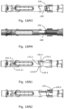
- Figure 16A to 16T collectively illustrate the relative and functional arrangement of the different structures during the sequence of states of the injection device 100, and thereby illustrate the operation of the device in details.
- the injection device 100 for sequentially delivering a plurality of fixed dosses comprises: a housing comprising an elongate housing structure 140, a cartridge holder 130, and a housing insert portion 160, an internal thread, a shield comprising the elongate shield structure 110 and the needle tip 119, a needle hub 125 comprising the fixedly attached needle cannula 104, a cap 105 removably mounted on the housing and adapted for covering a distal end of the shield, a cartridge 135 with a movably arranged cartridge plunger 136 and a drive mechanism comprising a torsional drive spring 108, a drive tube 180 and a piston rod 109 with an outer thread for cooperating with the internal thread of the housing, the piston rod is arranged in connection with the plunger 136, and wherein the torsional spring is adapted to provide a torque for rotating the drive tube 180 relative to the housing.
- the drive tube comprises a ratchet mechanism ensuring rotation in a dosing direction and blocking in a non-dosing direction.
- the drive tube is axially splined with the piston rod, whereby relative axial movement is allowed, and relative rotation is prevented.
- the drive tube is adapted to advance the piston rod, in response to rotating the drive tube in the dosing direction, and due to the threaded connection with the housing, the piston rod is adapted to advance the plunger 136 in the cartridge 135 to expel a fixed dose.
- the drive mechanism is adapted to be activated, by changing the drive tube from a distal position, wherein the drive mechanism is in a stationary mode, to a proximal position, wherein the drive mechanism is in a dosing mode.
- the drive tube In the distal position, the drive tube is rotationally locked to the housing. In the proximal position, the drive tube is rotationally unlocked from the housing, and the provided torque can rotate the drive tube a predetermined angel to expel the fixed dose.
- the piston rod In the stationary mode of the drive mechanism, the piston rod is rotationally and axially locked, and the piston rod is rotationally locked to the housing through the splined connection with the drive tube 180, and axially locked through the threaded connection with the housing.
- the torsion spring is pre-strained to deliver the plurality of doses without restraining during use.
- the drive mechanism is adapted to change mode upon activation, and as explained later the drive mechanism is adapted to be repeatably activated until the last dose has been expelled.
- the cap can be arranged in an axially locked position and an axially unlocked position.
- the cap can be changed between the positions by turning the cap relative to the housing. For the cap being in the axially unlocked position, the cap can be removed from the housing.
- the needle hub 125 is movably arranged on the housing and can be moved between the distal position and the proximal position relative to the housing.
- the needle hub 125 is arranged in connection with the cartridge and is rotationally locked relative to the housing.
- the proximal end of the needle cannula is arranged distally to a pierceable septum of the cartridge.
- the needle cannula extends through the septum and is positioned in fluid communication with the reservoir of the cartridge. I response to moving the needle hub from the distal to the proximal position, the needle cannula pierces the septum of the cartridge, and moves the cartridge a proximal distance relative to the housing and the axially locked piston rod.
- the shield can be arranged in different positions.
- An initial position defined by an initial angular position and a corresponding initial axial position.
- a locked position defined by a locked angular position and a corresponding locked axial position.
- An unlocked distal position defined by an unlocked angular position and a corresponding distal unlocked axial position.
- An unlocked proximal position defined by the unlocked angular position and a corresponding proximal unlocked axial position.
- the shield In the initial position, the shield is adapted to prevent an axial and clockwise movement, and adapted to allow a counterclockwise movement.
- the locked position the shield is adapted to prevent clockwise and axial movement. In this position, the shield is further adapted to allow a counterclockwise rotation.
- the shield In the unlocked distal position, the shield is adapted to prevent counterclockwise and distal movement of the shield, and further adapted to allow proximal movement. In the unlocked distal position, the shield is further adapted to allow a clockwise rotation, if the applied torque exceeds a predefined threshold. For the shield being in the initial position and the locked position the needle tip is covered by the shield. In the unlocked position, the shield is adapted to be moved from the unlocked distal position, wherein the needle tip is uncovered by the shield and wherein pressure in the reservoir can be released, and proximally to the unlocked proximal position, wherein the needle tip extends further from the shield and can be inserted into the subcutaneous layer of a subject.
- the shield can be manually operated between the different positions by the user. As appears for the shield being in the initial position, the locked position, the distal unlocked position and the proximal unlocked position, defines four different sets of angular and axial positions: three different angular position and four different axial positions.
- the connector can be arranged in an initial position initial position defined by an initial angular and initial axial position, wherein it is positioned rotationally locked to the middle guide 144 of the housing, wherein the middle guide 144 also prevents a distal movement of the connector.
- the connector is biased in the distal direction by return spring 107.
- Fig. 16A to 16T collectively illustrate the injection device 100 arranged in different states and intermediate arrangements, wherein an outer portion of the housing and an outer portion of the cap has been cut away to illustrate some of the internal structures.
- Figure 16A illustrates the injection device in the out-of-pack state, and shows the cap 105, the shield structure 110 the housing insertion portion 160, the cartridge holder 130, the connector 170, the drive tube 180 and the return spring 107, and the spring base 165.
- reference numbers are also provided for the proximal guide 162 of the housing insert portion, the stepwise helical guide 112 of the shield and the distal guide 142 of the housing.
- the user receives the device from the pharmacy and unpacks the device from the secondary packaging. By unpacking the user has provided the injection device in the out-of-pack state.
- FIG. 16B to 16E collectively illustrate the intermediate arrangements between the out-of-pack illustrated in figure 16A , and the cap unlocked state, illustrated in figure 16F .
- reference numbers are shown for details of the proximal guide 162 and the distal guide 142. The details are: the helical portion 162.1, the transverse portion 162.2, the axial portion 162.3, the first axial portion 142.1, the first transverse portion 142.2, the second axial portion 142.3 and the second transverse portion 142.4.
- Reference numbers for details of the stepwise helical guide 112 are shown in figure 16C and 16E .
- the details are: the proximal axial guide portion 112.1, the first proximal transverse guide portion 112.2, the second proximal transverse guide portion 112.3, the first proximal helical guide portion 112.4, the second proximal helical guide portion 112.5, the first middle transverse guide portion 112.6, the second middle transverse guide portion 112.7, a first distal helical guide portion 112.8, the second distal helical guide portion 112.9, the first distal transverse guide portion 112.10, the second distal transverse guide portion 112.11 and the distal axial guide portion 112.12.
- Reference numbers for details of the proximal guide 114 of the shield are shown in figure 16DC .
- the details are: the first left-handed helical portion 114.1, the first right-handed helical portion 114.2, the second right-handed helical portion 114.3.
- Reference numbers for details of the distal guide 172 of the connector is shown in figure 16C .
- the details are: the left-handed helical portion 172.1, the right-handed helical portion 172.2, the first axial portion 172.3.
- the first user operation is to turn the cap counterclockwise until it reaches the cap axially unlocked position, whereby the shield is changed from the initial position to the locked position, and whereby the device is changed from the out-of-pack state through a number of intermediate arrangements to the cap unlocked state, also referred to as the shield initiated state.
- fig. 16A illustrates the arrangement of the injection device provided in the out-of-pack state.
- the cap 105 is arranged in the axially locked position, and the shield is arranged in the initial position.
- a small circumferential clearance is provided between the axially extending rib 116 protruding from the inner surface of the cap and the axially extending rib 105.1 protruding from the outer surface of the shield.
- the protrusion on the inner surface of the cap 105.2 is releasably retained in the cap mount track 161 by the snap lock 161.1.
- Fig. 16B illustrates a first intermediate arrangement of the injection device.
- the circumferential clearance has been eliminated by the rotation, and an abutment has been provided between the axially extending rib 116 of the cap and the axially extending rib 105.1 of the shield.
- a torque will be transferred from the cap to the shield.
- a circumferential clearance is provided between the first proximal helical guide 112.4 of the shield and the helical portion 162.1 of the housing insert portion, allowing a relative counterclockwise rotation between shield and housing.
- the shield has been further rotated.
- the abutment between helical guide portions of the shield and the housing provides a combined rotational and proximal movement relative to the housing. Therefore, the step-wise helical guide 112 has been moved proximally along the helical guide portion 162.1.
- the step-wise helical guide portion comprises a front edge and a trailing edge defined according to the direction of the relative movement between shield and housing. Due to the relative movement, the area of the abutment becomes progressively smaller until the trailing edge of the first proximal helical guide portion 112.4 reaches the proximal edge of the helical portion 162.1.
- the abutment between the step-wise helical guide and the housing is shifted from abutment between helical portions to abutment between transverse portions, whereby the shield is guided in a pure rotation, in response to further counterclockwise rotation.
- the abutment between the first proximal helical guide portion 112.4 of the shield and the helical portion 162.1 of the housing is provided between a distal portion of the first proximal helical guide portion 112.4 (close to the trailing edge) and the trailing edge.
- the connector is arranged in the initial angular and axial position, wherein it is rotationally locked to the housing, and prevented from distal movement, the connector is biased in the distal direction by the return spring 107. Due to the proximal helical movement of the shield an abutment in a rest position has been established between the first left-handed helical portion 114.1 of the proximal guide of the shield and the left-handed helical portion 172.1 of the connector. In this position of the shield, a small axial clearance is provided between the second proximal helical guide portion 112.5 and the the first transverse portion 142.2, whereby pure axial movement in the proximal direction exceeding the clearance is prevented.
- the shield has been further rotated.
- the transverse guide portion 162.1 defines a first and a second edge, wherein the second edge is position counterclockwise to the first edge.
- the first middle transverse portion 112.6 comprises a front and a trailing edge defined according to the direction of the relative movement between shield and housing.
- the area of the abutment becomes progressively smaller until the trailing edge of the first middle transverse guide portion 112.6 reaches the second edge of the transverse portion 162.2.
- the abutment between the step-wise helical guide and the housing is shifted from abutment between transverse portions to abutment between helical portions, whereby the shield is guided in a helical movement, in response to further counterclockwise rotation.
- the abutment between the first middle transverse guide portion 112.6 of the shield and the transverse portion 162.2 of the housing is provided between the middle of the guide portion and the trailing edge.
- a small axial clearance is provided between the second middle transverse guide portion 112.7 and the first transverse portion 142.2 of the housing, whereby proximal movement is limited.
- the cap 105 In the cap unlocked and shield locked state, as illustrated in fig. 16F , the cap 105 is arranged in the axially unlocked position, and the shield is arranged in the locked position.
- the cap is positioned with the protrusion 105.2 on the inner surface of the cap at the second end of the circumferential track portion 161.3, whereby the protrusion 105.1 is angularly aligned with the axial track portion 161.2, and can be moved in the distal direction.
- the shield is arranged in the locked position, wherein abutment is established between the step-wise helical guide 112 and both the transverse portion 162.2 and the helical portion 162.1.
- the second user operation is to pull the cap in a distal direction, whereby the device is changed from the cap unlocked state to the cap-off state.
- the cap In the cap of state, as illustrated in fig. 16G , the cap has been removed from the main portion 102 of the injection device shown in fig. 16F .
- the position of the shield is unchanged in relation to the arrangement in fig. 16F , and is still in the locked position.
- the shield is axially locked, but allowed to perform a proximal helical movement guided by the abutment between the step-wise helical guide 112 and the helical portion 162.1 of the housing.
- the third user operation is to turn the shield, being in the locked position, in the counterclockwise direction until it reaches the unlocked position, and whereby the device has been changed from the cap-off state through a number of intermediate arrangements to the shield unlocked state.
- the shield 110 rotates relative to the connector 170 whereby the right-handed helical portion 172.2 slides along the first right-handed helical portion 114.2, and whereby the first left-handed helical portion 172.1 is brought out of abutment with the first left-handed helical portion 114.1 of the proximal guide of the shield.
- the fourth user operation is to push the shield, being in the unlocked distal position, in a proximal direction until it reaches the unlocked proximal position, and whereby the device has been changed from the shield unlocked state through a number of intermediate arrangements to the dosing state.
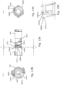
- the torsionally strained drive spring 109 has been compressed and brought into a compressed state. From the first arrangement of the device in the dosing state ( fig. 16L1 ) to the last illustrated arrangement in the dosing state ( figure 16N1 ), the drive tube has turned 360 degrees during a distal helical movement, i.e., a full rotation, and returned to the initial position in the housing ( fig. 13A and 13N3 ), wherein the drive tube is rotationally locked to the housing, and whereby a fixed dose has been expelled.
- the drive tube with the front edge of the distal helical surface portion 189 has travelled from a start dosing position illustrated in figure 16L3 , in the counterclockwise direction along the proximal helical surface portion 157 of the inner tubular portion 154 of the housing, to an intermediate shield unlocking position illustrated in fig. 16M3 and 16M4, wherein the axial portion 183.2 hits and abuts the axial portion 178.2 of the tab 178, as indicated on fig 16M2 .
- the drive tube with the front edge of the distal helical surface portion 189 continues the distal helical movement along surface portion 157, until it reaches the axial surface portion 156 of the inner tubular portion 154 of the housing.
- the drive spring is rotated by the torsionally pre-strained drive spring 108, and the helical surface portion of the drive tube is kept in contact with the helical surface portion 157 of the housing, as the compressed drive spring 108 expands during unwinding.
- the drive tube has returned to the initial position, which corresponds to that the drive tube has reached a stop dosing position, and further counterclockwise rotation has been prevented, as illustrated in fig. 13A and N3.
- the activation tab 178 can be moved proximally through the transverse opening in the outer helical structure 184, in response to the release of the axial and proximally oriented force on the shield, i.e, the pressure on the shield tip 119 is released as the device is lifted from the skin.
- the intermediate shield unlocking position and the stop dosing position defines three different sets of angular and axial positions: three different angular coordinates and three different axial coordinates.
- a trailing edge of the left-handed helical portion 172.1 moves slightly in the proximal direction along the second left-handed helical portion until a proximal edge of the second left-handed helical portion 114.1 has been exceeded.
- the connector has shifted from abutment with the left-handed helical portion 114.4 of the shield to abutment with the right-handed helical portion 114.3 of the shield, i.e., the abutment between the right-handed helical portion 172.2 of the connector and the second right-handed helical portion 114.3 of the shield has been reestablished.
- the connector Due to the right-handed helical abutment, the connector is urged in the counterclockwise direction under the distally oriented biasing force of the return spring 107.
- the connector arm 176 rotates along the first transverse portion 146.2 of the proximal guide of the housing and until an angular position of abutment between the axial surface 176.1 of the connector arm and second axial portion 143.3 of the proximal guide of the housing.
- additional abutment is provided between the third axial portion 174.5 of the middle guide of the connector the first axial portion 144.2 of the middle guide of the housing.
- the connector can only move the shield in the axial direction in a pure axial movement.
- the connector has been moved in a pure proximal axial direction, until the activation tab 178 has reached the position indicated with the patterned rectangle in fig. 16L3 .
- the drive tube 180 is consequently moved between the distal stationary position, wherein the drive tube is rotationally locked by the housing, to the proximal rotational position, wherein the drive tube will rotate relative to the housing due to the torsion provided by the drive spring 108.
- the activation tab 178 is retained on the proximal side of the helical structure 184 of the drive tube, whereby a split-dose has been prevented. If the pressure is released premature, i.e., before the stop dosing position is reached, the connector and the shield is moved in the distal direction until axial abutment between the distally oriented retention portion 178.3 of the activation tab 178 and the helical structure 184.
- the activation tab will slide along the helical structure 184 as the drive tube rotates to the stop dosing position, whereby the activation tab will be moved in a pure distal axial direction through the transverse opening in the helical structure 184.
- Figure 16M1-M3 illustrate the same arrangement of the injection device 100.
- Fig. 16M2 illustrates the device from the same angle as in Fig. 16M1 , but an angular portion of the connector has been cut away.
- Fig. 16M2 and M3 are seen from opposite sites (180 degrees rotation about the central axial axis).
- Fig. 16M4 illustrates the arrangement of fig. 16M3 in gray scale.
- Figure 16N1-N3 illustrate the same arrangement of the injection device 100.
- Fig. 16N2 illustrates the device from the same angle as in Fig. 16N1 , but an angular portion of the connector has been cut away.
- Fig. 16N2 and N3 are seen from opposite sites (180 degrees rotation about the central axial axis).
- the fifth user operation is to release the axially oriented force on the shield, by lifting the needle tip 119 from the skin, whereby the shield being in the unlocked proximal position, is moved in the distal direction until it reaches the locked position, and whereby the device has been changed from the dosing state through a number of intermediate arrangements to the relocked state.
- the right-handed helical portion 172.2 of the connector abuts the second right-handed helical portion 114.2 of the shield. Due to the helical abutment between connector and shield the shield is urged in the clockwise direction, whereby the distal axial portion 112.12 is urged towards the second axial portion 142.3 of the housing. Therefore, the shield is axially guided along the distal guide of the housing until a trailing edge of the helical portion 172.2 has reached a distal edge of the second axial portion 142.2, whereby the shield can rotate in the clockwise direction, in response to further distal movement, as illustrated in the intermediate arrangement shown in fig. 16P . During the clockwise rotation, illustrated by the intermediate arrangements shown in figs.
- the step-wise helical guide 112 slides between first transverse portion 142.2 and the transverse portion 162.2, while the connector biases the shield 110 and slides along the proximal guide 114 of the shield.
- the shield can move in a combined distal and rotational movement guided by the connector moving along the second-right handed helical portion 114.3 to the rest position in abutment with the first left-handed helical portion 114.1 of the proximal guide ( fig. 16S ).
- the connector 170 has moved in the distal direction guided by the first axial portion 144.2 of the middle guide of the housing preventing counterclockwise rotation, as illustrated in the last arrangement in the dosing state (Fig. 16N1 ) and the intermediate arrangements in figs. 16P and 16Q .
- a clockwise rotation of the connector is initiated.
- the connector arm or click arm 176 has travelled along the axial guide portions 146.3 and 146.4 and along the ramp portion 146.4 to the flush surface portion 146.5, whereby the click arm 176 has been radially compressed, as indicated in fig 16Q .
- the left-handed helical portion 174.4 slides along the middle guide 144 of the housing, which induces a clockwise rotation until the trailing edge of the helical portion 174.4 reaches the proximal edge of the first axial portion 144.2.
- connector has almost reached the rest position with the proximal guide of the shield, wherein the left-handed helical portion 172.1 abut the first left-handed helical portion 114.1, and the connector arm has returned to the abutment with the first axial portion 146.1 of the proximal guide, as illustrated in figure 16R .
- the connector arm has been reset, in its initial position and is ready to guide the connector during a new activation and dosing cycle.
- the fifth user operation is to put the cap on as illustrated in fig. 16T , hereby the protrusion 105.2 is inserted into the axial track portion 161.2, whereby it can be turned in order to arrange the device in the cap locked state, which was shown in fig 15B (cap locked state not shown in connection with detailed description of the operation).
- the axially extending rib is position for moving away from the protrusion 116, when the cap is turned into the locked position. Therefore, there is no interaction between the cap 105 and the shield 110, when the cap is locked.
- Figure 17-26 illustrate a second embodiment of an injection device 200 for delivering a plurality of fixed dosses according to the present disclosure.
- Figure 17 shows an exploded view of injection device, and figure 18 a cross sectional view.
- Figure 18-23 show further details of the individual structures and mechanism.
- Figure 25-26 illustrate in details the interrelation of the mechanical structures during operation.
- Figure 17 shows a cap 205, a shield tip 219, a shield following portion 220.1 of a cleaning module also comprising a movable portion, corresponding to the movable portion 120.2 in the first embodiment 1.
- Figure 17 further shows a needle hub 225 with a needle cannula 224, a tubular elongate housing structure 240, and a housing cap portion 260 to be connected at a distal end of the housing structure 240.
- the figure further shows a tubular elongate needle shield structure 210, a cartridge holder 230, a cartridge 235, a connector 270, a shield return spring 207, a drive tube 280, a dose drive spring 208, a piston rod 209, and a spring base 265.
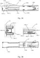
- FIG. 18 illustrates a cross sectional view of the injection device 200, wherein the injection device is in an out-of-pack state. The cross-sectional plane cuts through the windows 211 of the shield.
- the injection device comprises a housing assembly, providing a rigid frame with guides and connectors for guiding and connecting the other components of the device.
- the housing assembly comprises the housing cap portion 260, the tubular elongate housing structure 240, the cartridge holder 230 with a window 231 and the spring base 265. After final assembly these structures are fixedly connected, and the housing assembly can provide a frame of reference for describing the relative movement and position of the other structures.
- the elongate housing structure 140 comprises an internal thread 254.3 for engaging an outer thread of the piston rod.
- the injection device 200 comprises a drive mechanism and a triggering or activation mechanism.
- the drive mechanism comprises the piston rod 209, the drive spring 208, and the drive tube 280, and for expelling a dose the structures are operationally arranged in the housing.
- the triggering mechanism comprises the elongate shield structure 210 and the connector 280, and for triggering the dose expelling mechanism the structures are operationally arranged in the housing.
- the tubular portion 254 comprises a middle guide 244 comprising an outer axial portion 244.1 arranged symmetrically around the longitudinal axis at a first radial position and thereby defining a first diameter and an inner axial portion 244.2 arranged symmetrically around the longitudinal axis a second radial position, and thereby defining a second diameter.
- the injection device further comprises a needle shield assembly comprising the shield tip 219 and the elongate shield structure 210.
- the elongate shield structure 110 comprises a window 211 for inspection of the drug, the elongate shield can be arranged in a first position of overlapping with the cartridge holder window 231, and in a second position with no overlap, wherein a solid portion of the elongate shield structure covers the window 231 in the second position.
- the cap 205 is adapted for releasable mounting to the housing cap portion 260.
- the cap comprises an inner surface with a protrusion adapted to couple with a bayonet coupling track.
- the inner surface of the cap 105 further comprises an axially extending rib (not shown) protruding from the inner surface and adapted for transferring a torque to the shield structure 110 through an axially extending rib 216 on the outer surface of the shield.
- the cap 205 is structurally and functionally similar to the cap 105 of the first embodiment, with an exception that the cap 205 also encloses a main portion of the shield and the cartridge.
- the drive spring 208 is pre-strained or winded up and positioned between the spring base and the drive tube 280.
- the drive spring is further adapted to induce a torque on the drive tube, whereby the medicament can be expelled.
- the drive spring comprises torsional and compressible sections. The ability to drive the drive tube in an axial direction enables an end of dose mechanism, and to enable a resetting of the drive tube.
- Figure 19 illustrates a perspective view of features arranged at the inner surface of the tubular housing structure 240 in an axial cut of the housing.
- the tubular housing structure 240 comprises an outer tubular portion 243 and an inner tubular portion 254.
- the inner tubular portion 254 is integrally connected to the outer tubular portion.
- the outer tubular portion comprises an outer surface with an outer diameter and an inner surface with an inner diameter, wherein the outer tubular portion is adapted for accommodating the drive mechanism assembly and the relock tube 279.
- the housing structure 240 comprises a guide structure comprising an axial surface portion 256 providing a sliding surface and a rotational stop, and a helical surface portion 257 providing a sliding surface adapted for guiding the drive tube 280 during dosing.
- FIG 20 illustrate in detail the inner tubular portion 254 in a perspective view, wherein the outer tubular portion 243 has been cut away.
- the inner tubular portion comprises a tubular drive tube engaging portion 254.1 for accommodating a distal portion of the drive tube, and a tubular drive piston rod engaging portion 254.2 comprising a thread 254.3 for threadably engaging the piston rod 209.
- the piston rod engaging portion further comprises a connector 254.4 for making a snap connection with the cartridge holder 230.
- the piston washer comprises an outer thread and a rachet arm for cooperating with a thread and a toothed ring on the inner surface of the piston, whereby zero-point-adjustment is enabled, in analogy with the method described for the first embodiment.
- the drive tube 280 is axially splined to the piston rod.
- Figure 23A and 23B illustrate the drive tube 280 in perspective views from different angles.
- the drive tube 280 of the second embodiment comprises a closed guide track 284 comprising a first transverse portion 284.1, a right-handed helical portion 284.2, a left-handed helical portion 284.3.
- the transverse guide portion 284.1 comprises a proximally oriented surface providing a connector seat, wherein the connector is seated before and after activation of the drive tube.
- the transverse portion further comprises an abutment structure 283 comprising a distally oriented surface portion 283.1 providing an abutment surface for abutting the connector during activation.
- the right-handed helical portion 284.2 comprises a distal surface providing an abutment surface for the connector, in response to immature release of shield pressure, i.e., a split dose prevention feature.
- the left-handed helical portion 284.3 provides a ramp surface for rotating the connector at the end of dose, whereby resetting of the shield is initiated.
- the drive tube of the injection device 200 comprises a guide structure comprising an axial surface portion 282 adapted for slidably engaging the axial surface portion 256 of the housing in a rotationally locked arrangement, and a helical surface portion 289 for slidably engaging the helical surface portion 257 of the housing during dosing.
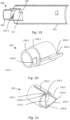
- Figure 24 shows a perspective view of the cylindrical elongate shield structure 210.
- the proximal portion of the shield is to be arranged inside the connector 270 which again is to be arranged inside the housing portions 240, 260.
- the elongate shield structure 210 comprises a tubular portion comprising an outer surface with an outer diameter and an inner surface with an inner diameter.
- the axially extending rib 216 is positioned at the distal end ant protrudes from the outer surface.
- the rib is adapted for cooperating with the internal rib of the cap 205.
- the shield structure 210 further comprises a radial guide 212 arranged at the proximal end and extending radially, whereby the shield is adapted for cooperating with the connector 270.
- the elongate shield structure 210 further comprises a proximal guide 214 positioned at the proximal end of the shield structure 210.
- the proximal guide 214 is adapted to cooperate with the connector 270, and the relock tube 279.
- the proximal guide 214 extends in the axial and circumferential direction and comprises a first transverse portion 214.1, an axial portion 214.2, a right-handed helical portion 214.3, and a second transverse portion 214.4.
- the proximal guide 214 further comprises a cut-out 214.5 providing a rotational lock, for locking the shield in a shield initiated state, wherein it cannot be returned to an out-of-pack state.
- the cut-out provides a right-handed helical guide portion 214.6.
- the guide portions 214.1-214.4 are all surface portions providing a proximal face of the proximal guide 214.
- Figure 22 shows a perspective view of the connector 270 to be arranged inside the tubular housing portions 240, 260 and between the elongate shield structure 110 and the drive tube.
- the connector 270 is adapted for establishing a connection between the shield 210 and the drive tube 280, and for activating the drive tube 280.
- the connector 270 comprises a distal guide 272 adapted to cooperate with the proximal guide 114 of the shield.
- the distal guide 272 is extending in the circumferential direction and comprises a transverse surface portion 272.1 being distally oriented surface.
- the connector further comprises a step-wise helical track 274 for cooperating with the radial guide 212 of the shield.
- the step-wise helical track comprises a distal transverse portion 274.1, a distal helical portion 274.2, a middle transverse portion 274.3, a proximal helical portion 274.4 and a proximal transverse portion 274.5. Due to the helical portions of the step-wise helical track, a rotational movement of the shield 210 can be transferred into a proximal movement of the shield, and due to the transverse portions of the step-wise helical track 274, a distally oriented force on the shield can be transferred to the connector 270, whereby the shield can move distally. If the shield exerts a distal force on the helical portions of the step-wise helical track 244, the connector may move distally or both distally and rotationally.
- the connector 270 comprises a first tubular portion 270.1 with a full 360 degree circumference, and a second tubular portion 270.2 with two cut-outs, whereby the remaining portions of the second tubular portion forms two axially extending tube portions 276.
- the first tubular portion comprises the step-wise helical track 274, and the two axially extending tube portions 276 comprises a distal transverse surface 272.1 forming the distal guide 272, a first axial surface providing a first axial guide 276.1, and a second axial surface, positioned clockwise to the first surface, providing a second axial guide 276.2.
- the shield can be arranged within, the first tubular portion 270.1 with the radial guide 212 extending through the step-wise helical track 274.
- the axially extending tube portions 276 extends in the proximal direction from the inner surface of the first tubular portion 270.1, and therefore has a smaller diameter.
- the transverse surface portion 272.1 is provided on the distally oriented surface of the axially extending tube portions 276, and as the diameter of the tube portions 276 corresponds to the diameter of the shield 210, the proximal guide 214 having a proximally oriented surface is adapted to cooperate with the transverse guide portion 272.1.
- the diameter of the axially extending tube portions 276 further corresponds to the diameter of the inner axial portion 244.2 of the middle guide, whereby the axially extending tube portions 276 can cooperate with the inner axial portion 244.2.
- the connector 270 is having an outer surface with an outer diameter and an inner surface with an inner diameter. As illustrated on figure 18 , which is a cross sectional view of the injection device 200, the outer surface of the first tubular potion 270.1 of the connector is arranged in close proximity with the inner surface of the tubular housing cap portion 260.
- the axially extending tube portions 276 surrounds the inner tubular portion 254 of the housing and the drive tube 280.
- the axially extending arms 276 are further adapted to cooperate with the middle guide 244.1 of the housing and thereby guide the movement of the connector relative to the housing.
- the connector 270 further comprises an activation tab 278 arranged at the proximal end of the axially extending tube portions 270.2, and extending radially from the inner surface in a negative radial direction, i.e., towards the centre of the tubular portion.
- the activation tab 278 extends into the closed guide track 284 of the drive tube.
- the activation tab 278 comprises a first transverse portion 278.1 providing a proximally oriented contact surface adapted for engaging the distally oriented surface 283.1 of the abutment structure in the transverse portion 284.1 of the closed guide track, and thereby enabling a proximal movement and activation of the drive tube 280.
- the relock tube 279 comprises a first tubular portion 279.1, and a second tubular portion with two cut-outs, whereby the remaining portions of the second tubular portion forms two axially extending tube portions 279.2.
- the relock tube comprises an axially extending guide track 279.4 extending from a relatively small distance from the proximal end (e.g. 1/10 of the length of the relock tube) to the distal end.
- the two axially extending tube portions 279.2 comprises an axial guide portion 279.5, a first transverse guide portion 279.6, a right-handed helical portion 279.7, and a second transverse portion 279.8.
- the axially extending tube portions 279.2 further comprises an axial portion 279.9 providing a rotational stop and axial guide for the connector.
- the axially extending tube portions 279.2 extends in the proximal direction from the inner surface of the first tubular portion 279.1, and therefore has a smaller diameter.
- the helical and transverse guide portions 279.6-279.8 is provided on the distally oriented surface of the axially extending tube portions 279.2, and as the diameter of the tube portions 279.2 corresponds to the diameter of the shield 210, the proximal guide 214 having a proximally oriented surface is adapted to cooperate with the helical and transverse guide portion 279.8-279.8.
- the diameter of the axially extending tube portions 279.2 further corresponds to the diameter of the inner axial portion 244.2 of the middle guide.
- the diameter of the first tubular portion corresponds to the diameter of the outer axial portion 244.1 of the middle guide.
- the axially extending guide track 279.4 is adapted to cooperate with the outer portion 244.1 of the middle guide, whereby the relock tube 279 is rotationally locked and axially guided between a distal position defined by the proximal end of the guide track 279.4 and a proximal position ( Fig. 18 shows that they may be an axial play between the outer portion 244.1 and the proximal end of the track).
- the relock tube 279 is having an outer surface with an outer diameter and an inner surface with an inner diameter.
- the outer surface of the first tubular potion 279.1 of the relock tube is arranged in close proximity with the inner surface of the outer tubular portion 243 of the housing, and the return spring is position between the spring base 265 and a proximal edge of the relock tube 279, whereby the relock tube can be distally biased, in response to a proximal movement.
- the axially extending tube portions 279.2 surrounds the inner tubular portion 254 of the housing, and can cooperate with the axially extending tube portions 270.2 of the connector.
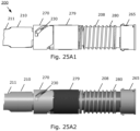
- Figure 25A to 26B collectively illustrate the relative and functional arrangement of the different structures during the sequence of states of the injection device 200, and thereby illustrate the operation of the device in details.
- the injection device 200 for sequentially delivering a plurality of fixed dosses comprises: a housing comprising an elongate housing structure 240, a cartridge holder 230, and a housing cap portion 260, an internal thread, a shield comprising the elongate shield structure 210 and the needle tip 219, a needle hub 225 comprising the fixedly attached needle cannula 204, a cap 205 removably mounted on the housing and adapted for covering a main portion of the shield, a cartridge 235 with a movably arranged cartridge plunger or piston 236 and a drive mechanism comprising a torsional drive spring 208, a drive tube 280 and a piston rod 209 with an outer thread for cooperating with the internal thread of the housing, the piston rod is arranged in connection with the piston 236, and wherein the torsional spring is adapted to provide a torque for rotating the drive tube 280 relative to the housing.
- the drive tube comprises a ratchet mechanism 281, 265.1 ensuring rotation in a dosing direction and blocking in a non-dosing direction.
- the drive tube is axially splined with the piston rod, whereby relative axial movement is allowed, and relative rotation is prevented.
- the drive tube is adapted to advance the piston rod, in response to rotating the drive tube in the dosing direction, and due to the threaded connection with the housing, the piston rod is adapted to advance the piston 236 in the cartridge 235 to expel a fixed dose.
- the drive mechanism is adapted to be activated, by changing the drive tube from a distal position, wherein the drive mechanism is in a stationary mode, to a proximal position, wherein the drive mechanism is in a dosing mode.
- the drive tube In the distal position, the drive tube is rotationally locked to the housing. In the proximal position, the drive tube is rotationally unlocked from the housing, and the provided torque can rotate the drive tube a predetermined angel to expel the fixed dose.
- the piston rod In the stationary mode of the drive mechanism, the piston rod is rotationally and axially locked, and the piston rod is rotationally locked to the housing through the splined connection with the drive tube 280, and axially locked through the threaded connection with the housing.
- the torsion spring 208 is pre-strained to deliver the plurality of doses without restraining during use.
- the drive mechanism is adapted to change mode upon activation, and as explained later the drive mechanism is adapted to be repeatably activated until the last dose has been expelled.
- the cap can be arranged in an axially locked position and an axially unlocked position.
- the cap can be changed between the positions by turning the cap relative to the housing. For the cap being in the axially unlocked position, the cap can be removed from the housing.
- the shield can be arranged in different positions.
- An initial position defined by an initial angular position and a corresponding initial axial position.
- An unengaged position defined by an unengaged angular position and a corresponding unengaged axial position.
- An engaged distal position defined by an engaged angular position and a corresponding distal engaged axial position.
- An engaged proximal position defined by the engaged angular position and a corresponding proximal engaged axial position.
- the shield In the initial position, the shield is adapted to allow a counterclockwise movement.
- the unengaged position the shield is adapted to prevent clockwise movement and to allow clockwise movement.
- the shield is not engaged with the connector, in the sense that a proximal movement of the shield is not transferred to a proximal movement of the connector, whereby the shield cannot activate the drive tube in this position.
- the shield In the engaged distal position, the shield is adapted to prevent counterclockwise and distal movement of the shield, and further adapted to allow proximal movement.
- the shield In the engaged distal position, the shield is further adapted to allow a clockwise rotation, if the applied torque exceeds a predefined threshold. For the shield being in the initial position and the unengaged position the needle tip is covered by the shield.
- the shield In the engaged position, the shield is adapted to be moved from the engaged distal position, wherein the needle tip is uncovered by the shield and wherein pressure in the reservoir can be released, and proximally to the engaged proximal position, wherein the needle tip extends further from the shield and can be inserted into the subcutaneous layer of a subject. In this position further proximal movement may be prevented by the shield tip 119 being blocked against the needle hub 125.
- the shield can be manually operated between the different positions by the user. As appears for the shield being in the initial position, the unengaged position, the distal engaged position and the proximal engaged position, defines four different sets of angular and axial positions: three different angular position and four different axial positions.
- the connector can be arranged in an initial or first position defined by a first angular and a corresponding distal position, wherein the connector is allowed to move to a proximal position, guided along the rotationally locked relock tube 279 until the connector 270 meets an axial stop on the housing or the shield tip 219 abuts the hub 225.
- the connector can therefore further be arranged in a second position defined by the first angular position and the proximal position.
- the connector can be arranged in a third position defined by a second angular position and a corresponding distal position, wherein the first and the third positions are defined by the same axial positions.
- Fig 25A to 26B collectively illustrate a portion of the injection device 200 arranged in different states and intermediate arrangements, wherein an outer portion of the housing and the entire cap has been cut away to illustrate some of the internal structures.
- Each illustrated state is illustrated with a figure wherein some of the internal components are hidden by the connector and the relock tube, e.g., 25B1, and each illustrated state is illustrated with a figure, wherein the outer portion of the relock tube and a portion of the outer portion of the connector has been removed, e.g., 25B3.
- Some illustrated states are also provided grayscale illustrations, e.g., 25B2 corresponding to 25B1 and 25B4 corresponding to 25B3.
- Figure 25A illustrates a portion of the injection device 200 in the out-of-pack state, and shows the shield structure 210, the cartridge holder 230, the connector 270, the drive tube 280 and the return spring 207, the relock tube 279, and the spring base 265.
- Figure 25A1 illustrates the portion of the injection device in black and white
- figure 25A2 illustrates the same in grayscale to better illustrate the different components of the construction.
- the first user operation is to turn the cap counterclockwise until it reaches the cap axially unlocked position, whereby the shield is changed from the initial position to the unengaged position, and whereby the device is changed from the out-of-pack state to the cap unlocked state, as shown in fig. 25B1 and B2 .
- the cap unlocked state the cap can be moved axially.
- the cap unlocked state is also referred to as the shield-initiated state, as the shield has initiated the device, or the shield unengaged state, as the shield is not engaged with the connector to activate the device or the non-activation state as the shield cannot activate the drive mechanism.
- the shield 210 in the embodiment 200 is not necessarily axially locked to the housing in this state, but as the shield does not engage the connector, an axial movement cannot be transferred from the shield to the connector, and the connector cannot be moved to activate the drive tube 280.
- the radial guide 212 of the shield engages the step-wise helical track 274 of the connector 270, during the proximal helical movement of the shield from the initial to the unengaged position, the radial guide 212 abuts a proximal surface of the distal helical guide portion 274.2 of the step-wise helical track.
- the radial guide rests on the middle transverse portion 273.4, wherein there are no proximal sides on the track 274.
- the shield has moved the relock tube 279 proximally against the biasing force of the return spring 208, and in the unengaged position the axially extending portions 279.2 of the relock tube has moved into the cut-out 214.5 whereby a rotational lock is provided.
- the right-handed helical portion 279.7 of the relock tube abuts the right-handed helical guide portion 214.6 of the cut-out, and the right-handed helical portion 214.3 of the proximal guide, and thereby urges the shield in the distal direction.
- the distal force is transferred from the shield to the connector, through the abutment between the radial guide 212 and the track 274, whereby the connector is also biased in the distal direction. Therefore, in the following states the relock tube 279, the shield 210 and the connector are distally biased.
- the shield does not extend to the spring base and therefore not is compressed. However, eventhough the illustrated embodiment is a little imprecise, the shield is at least slightly compressed in this state. Otherwise, the components would rattle inside the device when turned from up to down or vice versa.
- the second user operation is to pull the cap in a distal direction, whereby the device is changed from the cap unlocked state to the cap-off state.
- figure 25B1 and B2 also illustrate the cap-off state.
- the third user operation is to turn the shield, being in the unengaged position or non-activation position (as it cannot activate the drive mechanism), in the counterclockwise direction until it reaches the engaged distal position or activation position, and whereby the device has been changed from the cap-off state to the shield unlocked state.
- the shield rotates in a proximal helical movement guided by the distal helical portion 274.4 followed by a pure rotational movement guided by the proximal transverse portion 274.5.
- the right-handed helical guide portion 214.6 of the cut-out and the right-handed helical portion 214.3 of the shield slides in abutment with the right-handed helical portion 279.7 of the relock tube, whereby the rotationally locked relock tube 279 is forced in the proximal direction.
- the abutment between the helical portion 279.7 of the relock tube and the helical portions 214.7, 214.3 of the shield shifts to an abutment between the right-handed helical portions 214.3, 279.7 only and then to an abutment between the second transverse portion 214.4 of the proximal guide and the first transverse guide portion 279.6 of the relock tube.
- the abutment surface between the second transverse portion 214.4 of the shield and the first transverse portion 279.6 of the relock tube extends in a direction normal to the biasing force of the return spring, the abutment provides a static position of the relock tube 279 and the shield 210.
- a releasable locking mechanism is provided between the shield 210 and the relock tube 279.
- a torque exceeding a release threshold torque is required.
- the first transverse surface portion 214.1 of the proximal guide of the shield and the transverse surface portion 272.1 are brought into abutment, and during the pure rotational movement the shield slides relative to the connector until abutment between the axial portion 276.1 of the axially extending portion 276 and the axial portion 214.2 of the proximal guide.
- the fourth user operation is to push the shield, being in the engaged distal position, in a proximal direction until it reaches the engaged proximal position, and whereby the device has been changed from the shield unlocked state to the dosing state.
- the dosing state is illustrated by the arrangements shown in fig 25D to 25E .
- the shield moves in a proximal and pure axial movement guided by the relock tube travelling along the middle guide 144.
- the, by the shield, engaged relock tube 179 translates proximally to compress the return spring 208 even further, and the, by the shield, engaged connector translates proximally, whereby the activation tab 278 engages a proximal surface of the transverse portion 284.1 of the closed guide track, and wherein the drive tube also is translated proximally.
- the connector abuts the axial portion 114.2 of the proximal guide of the shield, and the first transverse guide portion 279.6 of the relock tube abuts the second transverse portion 214.4 of the proximal guide of the shield to transfer an axial distal force from the relock tube 279, through the shield 210 and to the connector 270.
- the proximal portion 278.2 of the activation tab 278 is brought out of abutment with the right-handed helical track, whereby the connector is no more prevented in moving in a distal direction.
- the connector will move axially in a distal direction and rotate, in response to releasing the pressure from the shield, whereby the connector will move into engagement with the left-handed helical portion 184.3 of the drive-tube.
- the automatic relock mechanism has been initiated.
- the fifth user operation is to release the axially oriented force on the shield, by lifting the needle tip 219 from the skin, whereby the shield being in the engaged proximal position, is moved in the distal direction until it reaches the unengaged position, and whereby the device has been changed from the dosing state through an intermediate arrangement shown in figure 25F to the unengaged state or non-actuation state shown in figure 25G .
- Figure 25F illustrates an intermediate arrangement between the dosing state and the unengaged state shown in figure 25G , wherein the drive tube has rotated into abutment with the axial portion 257, whereby the dose is completed.
- the activation tab 278 has shifted to abutment with the left-handed helical portion 284.3 and due to the compression from the return spring 207, the activation tab 278 has been forced to move along the left-handed helical track and thereby rotate and axially move the connector 270 to the second angular and distal position.
- the force from the compression spring is transferred from the relock tube through the shield and to the connector.
- the shield has been rotated due to the abutment between the connector and the axial portion 214.2 of the proximal guide of the shield. Due to the rotation of the shield, and as the relock tube is rotationally locked, the abutment between the shield and the relock tube has shifted to abutment between the right-handed helical portion 214.3 of the shield and the right-handed helical guide 274.7 of the relock tube.
- the helical abutment surface allows an axial movement of the relock tube 279 to be transferred into a rotational movement of the shield, and as the relock tube is distally biased, the relock tube is moved distally and the shield is rotated into the unengaged position, whereby the first transverse portion 214.1 of the locking structure 215 of the shield is brought out of abutment with transverse portion 272.1 of the distally oriented transverse guide portion 272 of the connector. As the two transverse portions 214.1, 272.1 are transverse, they can be forced to slide apart in response to the application of relative rotation.
- the fifth user operation is to put the cap on, which is not illustrated for the injection device 200, hereby the protrusion on the inner surface of the cap is inserted into an axial track portion on the housing, whereby it can be turned in order to arrange the device in the cap locked state.
- the cap locked state for injection device 200 is not illustrated.
- the cap 205 does not engage the shield, when rotated back to the locked state, and the shield is therefore not pushed toward the initial position.
- Figures 26A and 26B illustrate two arrangement in taking the second or higher number of dose, in case the connector does not rotate back to its first position.
- the connector 270 can either be left in the third position with a second angular position as shown in figure 25G2 , or it can be forced by the shield 210 to rotate to the first position with the first angular position, as the radial guide slides distally along the proximal helical guide 274.4. In the latter case, a new dose will start from the arrangement shown in figure 25B .
- a new dose will start from the arrangement shown in figure 25G2 , and continue to the arrangement shown in figure 26A , wherein the shield urges the relock tube in the proximal direction until the axial portion 214.2 of the shield abuts the axially extending portions 270.2 of the connector.
- the connector is pushed back to the first position with the first angular position as shown in figure 26 . From here the next dose continues as described from figure 25C .
Landscapes
- Health & Medical Sciences (AREA)
- Vascular Medicine (AREA)
- Engineering & Computer Science (AREA)
- Anesthesiology (AREA)
- Biomedical Technology (AREA)
- Heart & Thoracic Surgery (AREA)
- Hematology (AREA)
- Life Sciences & Earth Sciences (AREA)
- Animal Behavior & Ethology (AREA)
- General Health & Medical Sciences (AREA)
- Public Health (AREA)
- Veterinary Medicine (AREA)
- Infusion, Injection, And Reservoir Apparatuses (AREA)
Claims (15)
- Arzneimittelabgabevorrichtung (100, 200) zum Abgeben einer festgelegten Dosis, wobei die Arzneimittelabgabevorrichtung umfasst:- eine Gehäusebaugruppe,- einen Arzneimittelbehälter mit einem Kolben- einen Antriebsmechanismus, umfassend eine Kolbenstange (109, 209), die betriebsmäßig in der Gehäusebaugruppe angeordnet und zum Vorschieben des Kolbens ausgelegt ist, um ein Arzneimittel während der Dosierung auszustoßen, und ein Antriebsrohr (180, 280), das betriebsmäßig mit der Kolbenstange (109, 209) angeordnet ist, wobei das Antriebsrohr (180, 280) ausgelegt ist, um in Bezug auf die Gehäusebaugruppe axial beweglich und zu sein und in einem stationären Zustand drehgesperrt zu sein, und ausgelegt ist, um in einem Dosierzustand in Bezug auf das Gehäuse axial beweglich und drehbar zu sein, wobei der Antriebsmechanismus für eine axiale Bewegung und Drehung des Antriebsrohrs (180, 280) in dem Dosierzustand ausgelegt ist und dadurch die Kolbenstange (109, 209) vorschiebt, um die festgelegte Dosis in Reaktion auf eine Aktivierung abzugeben;- einen Aktivierungsmechanismus zum Aktivieren des Antriebsmechanismus in Reaktion auf die Bewegung des Antriebsrohrs in einer axialen Richtung,wobei die Gehäusebaugruppe eine Führungsstruktur zum Führen des Antriebsrohrs während der Aktivierung und der Abgabe einer Dosis umfasst, wobei die Führungsstruktur einen axialen Abschnitt (156, 256) umfasst, der eine Gleitfläche zum Führen des Antriebsrohrs während der Aktivierung und zum Bereitstellen eines Drehanschlags, der eine Dosierungsendposition definiert, bereitstellt, und einen Umfangsabschnitt (157, 257), der eine Gleitfläche bereitstellt, die zum Führen des Antriebsrohrs (180, 280) während der Dosierung ausgelegt ist;wobei das Antriebsrohr (180, 280) eine Führungsstruktur, die einen axialen Abschnitt (182, 282), der ausgelegt ist, um mit dem entsprechenden axialen Abschnitt der Gehäusebaugruppe zur Aktivierung gleitend in Eingriff zu kommen, und einen Umfangsabschnitt (189, 289) zum gleitenden Eingriff mit dem entsprechenden Umfangsabschnitt der Gehäusebaugruppe während der Dosierung, umfasst,wobei das Antriebsrohr (180, 280) ohne Drehung entlang des axialen Abschnitts (156, 256) geführt werden kann und dadurch bei Aktivierung von dem stationären Zustand in den Dosierzustand übergehen kann, wobei das Antriebsrohr (180, 280) durch den Antriebsmechanismus in dem Dosierzustand axial bewegt und gedreht werden kann, und wobei das Antriebsrohr (180, 280) in Reaktion auf die Aktivierung des Antriebsmechanismus entlang des Umfangsabschnitts (157, 257) bis zu dem Ende der Dosisposition geführt werden kann und dadurch von dem Dosierzustand in den stationären Zustand übergehen kann.
- Arzneimittelabgabevorrichtung nach Anspruch 1, wobei die Führungsstruktur (156, 157, 256, 257) der Gehäusebaugruppe eine geschlossene Führung ist, die einen Arbeitszyklus für das Antriebsrohr bereitstellt, und wobei eine Anfangsposition und eine Enddosisposition des Antriebsrohrs die gleiche ist.
- Arzneimittelabgabevorrichtung nach einem der vorhergehenden Ansprüche, wobei der Umfangsabschnitt (157, 257) der Führungsstruktur der Gehäusebaugruppe ein schraubenförmiger Abschnitt (157, 257) ist, und wobei der entsprechende Umfangsabschnitt (189, 289) des Führungsabschnitts des Antriebsrohrs (180, 280) ein schraubenförmiger Abschnitt (189, 289) ist, der dem schraubenförmigen Abschnitt (157, 257) der Gehäusebaugruppe entspricht.
- Arzneimittelabgabevorrichtung nach einem der vorhergehenden Ansprüche, wobei das Antriebsrohr axial mit der Kolbenstange verzahnt ist, wodurch eine relative axiale Bewegung ermöglicht und eine relative Drehung verhindert wird, und wodurch die Kolbenstange (109, 209) in Reaktion auf die Drehung des Antriebsrohrs (180, 280) vorgeschoben wird.
- Arzneimittelabgabevorrichtung nach einem der vorhergehenden Ansprüche, wobei der Antriebsmechanismus ferner einen Motormechanismus umfasst, um das Antriebsrohr zur Abgabe einer Dosis in Reaktion auf die Aktivierung des Antriebsmechanismus in Drehung zu versetzen,wobei das Antriebsrohr axial mit der Kolbenstange verzahnt ist, wodurch das Antriebsrohr (180, 280) in Bezug auf die Kolbenstange (109, 209) axial beweglich und drehfest ist,wobei der Antriebsmechanismus ferner einen Rückfuhrmechanismus umfasst, um das Antriebsrohr in einer axialen Richtung zu bewegen und dadurch das Antriebsrohr nach der Aktivierung zurückzuführen.
- Arzneimittelabgabevorrichtung nach einem der vorhergehenden Ansprüche, wobei der Aktivierungsmechanismus einen beweglich angeordneten Verbinder (170, 270) umfasst, wobei der Verbinder eine Aktivierungslasche (178, 278) umfasst, und wobei die Aktivierungslasche ausgelegt ist, um mit einem Flächenabschnitt (183.1, 283.1) des Antriebsrohrs in Reaktion auf das Bewegen des Verbinders in einer axialen Richtung in Eingriff zu treten, wobei der Verbinder betriebsmäßig mit dem Antriebsmechanismus verbunden und zum Auslösen des Antriebsmechanismus ausgelegt ist, wobei der Flächenabschnitt (183.1, 283.1) in einer Richtung zu der Aktivierungslasche (178, 278) hin ausgerichtet ist.
- Arzneimittelabgabevorrichtung nach Anspruch 3 oder Anspruch 3 und einem der Ansprüche 4-6, wobei der stationäre Zustand umfasst, dass das Antriebsrohr (180) in einer Ausgangsposition angeordnet werden kann, wobei das Antriebsrohr (180, 280) in einer ersten axialen Position, in der das Antriebsrohr sich in einer axialen Richtung bewegen kann und durch das Gehäuse in der anderen axialen Richtung gesperrt wird, und in einer ersten Winkelposition angeordnet werden kann, in der das Antriebsrohr durch das Gehäuse in einer Richtung drehgesperrt und in der anderen Drehrichtung durch den Antriebsmechanismus eingeschränkt ist, wobei die Führungsstruktur (182, 189, 282, 289) des Antriebsrohrs an dem axialen Abschnitt (156, 256) der Führungsstruktur der Gehäusebaugruppe und dem schraubenförmigen Abschnitt (157, 257) der Führungsstruktur der Gehäusebaugruppe anliegt; wobei der Dosierzustand umfasst:- das Antriebsrohr kann in einer ersten Dosierposition angeordnet werden, wobei das Antriebsrohr (180, 280) in einer zweiten axialen Position und der ersten Winkelposition angeordnet werden kann, wodurch der Antriebsmechanismus aktiviert wird und- einer zweiten Dosierposition angeordnet werden, wobei das Antriebsrohr in einer axialen Position zwischen der ersten und der zweiten axialen Position und einer von der ersten Winkelposition verschiedenen Winkelposition angeordnet werden kann, wobei der schraubenförmige Abschnitt (189, 289) der Führungsstruktur gleitend entlang des schraubenförmigen Abschnitts (157, 257) der Führungsstruktur der Gehäusebaugruppe angeordnet ist, wodurch eine Dosis ausgestoßen werden kann.
- Arzneimittelabgabevorrichtung nach Anspruch 7, wobei der Verbinder (170, 270) ausgelegt ist, das Antriebsrohr zwischen der ersten axialen und der zweiten axialen Position zu bewegen, wodurch die Position des Antriebsrohrs (180, 280) in Reaktion auf das Bewegen des Verbinders (170, 270) von einer ersten axialen zu einer zweiten axialen Position von der Ausgangsposition in die erste Dosierposition geändert wird, und wobei der Antriebsmechanismus ausgelegt ist, das Antriebsrohr (180, 280) zu drehen und dadurch die Position des Antriebsrohrs (180, 280) von der ersten Dosierposition in die zweite Dosierposition und in die Ausgangsposition zu ändern, in Reaktion auf die Aktivierung des Antriebsmechanismus durch Einstellen des Antriebsrohrs (180, 280) in die erste Dosierposition.
- Arzneimittelabgabevorrichtung nach Anspruch 5 oder Anspruch 5 und einem der Ansprüche 6-8, wobei der Motormechanismus eine Torsionsantriebsfeder (108, 208) zum Drehen des Antriebsrohrs durch Abwickeln umfasst, wobei die Antriebsfeder (108, 208) zwischen der Gehäusebaugruppe und dem Antriebsrohr (180, 280) befestigt ist, wobei die Antriebsfeder ferner komprimierbar ist, um das Antriebsrohr während der Drehung axial zu bewegen, wodurch die Antriebsfeder den Rückstellmechanismus zum Zurückführen des Antriebsrohrs nach der Aktivierung bereitstellt.
- Arzneimittelabgabevorrichtung nach Anspruch 9, wobei die Antriebsfeder (108, 208) einen komprimierbaren Abschnitt (108.4) umfasst.
- Arzneimittelabgabevorrichtung nach Anspruch 6 und einem der Ansprüche 9-10, wobei die Aktivierungslasche (178, 278) des Verbinders (170, 270) einen quer verlaufenden Flächenabschnitt umfasst und wobei der in Eingriff bringbare Flächenabschnitt (183.1, 283.1) des Antriebsrohrs quer verläuft, wodurch die Initiierung der Dosierung durch eine von der Torsionsantriebsfeder induzierte Drehbewegung bereitgestellt werden kann, in Reaktion auf die Aktivierung des Antriebsmechanismus.
- Arzneimittelabgabevorrichtung nach Anspruch 5 oder Anspruch 5 und einem der Ansprüche 6-8, wobei der Motormechanismus eine Druckantriebsfeder umfasst, wobei die Aktivierungslasche (178, 278) einen schraubenförmigen Flächenabschnitt umfasst, wobei der in Eingriff bringbare Flächenabschnitt (183.1, 283.1) des Antriebsrohrs zum Aktivieren des Antriebsrohrs einen schraubenförmigen Flächenabschnitt umfasst, wobei die Aktivierungslasche ausgelegt ist, um eine anfängliche Drehung des Antriebsrohrs in der Dosierungsrichtung in Reaktion auf das Eingreifen der Lasche (183, 283) und das Bewegen des Antriebsrohrs gegen die Vorspannkraft der Druckfeder und zwischen der distalen und der proximalen Position zu bewirken, und wobei der schraubenförmige Abschnitt (157, 257) der Gehäusebaugruppe und der Druckfeder ausgelegt ist, um eine weitere Drehung des Antriebsrohrs in Reaktion auf die anfängliche Drehung bereitzustellen, wodurch eine vollständige feste Dosis abgegeben werden kann.
- Arzneimittelabgabevorrichtung nach einem der vorhergehenden Ansprüche, wobei die Kolbenstange (109, 209) eine sich axial erstreckende Spur (109.2) umfasst, wobei das Antriebsrohr (180, 280) nach innen gerichtete Vorsprünge (180.2) umfasst, die ausgelegt sind, um gleitend in die axiale Spur (109.2) einzugreifen, wodurch das Antriebsrohr (180, 280) in Bezug auf die Kolbenstange (109, 210) drehfest ist und sich axial bewegen kann.
- Arzneimittelabgabevorrichtung nach einem der vorhergehenden Ansprüche, wobei die Arzneimittelabgabevorrichtung ferner eine Abschirmung (110, 210) zum Betätigen des Verbinders (170, 270) umfasst, wobei die Abschirmung ausgelegt ist, einen Abschnitt einer Nadelkanüle (124) in einer distalen Position abzudecken und die Nadelkanüle in einer proximalen Position freizulegen, wobei, wenn sich die Abschirmung in der proximalen Position befindet, die Nadel in einen Probanden eingeführt werden kann, und wobei die Abschirmung ausgelegt ist, den Verbinder (170, 270) zwischen der ersten und der zweiten axialen Position zu bewegen, in Reaktion auf das Bewegen der Abschirmung von der distalen zu der proximalen Position, wobei die erste und die zweite Position des Verbinders eine distale und eine proximale Position ist.
- Arzneimittelabgabevorrichtung nach Anspruch 1 oder 2, wobei die Kolbenstange axial mit der Gehäusebaugruppe verzahnt ist, wodurch die Kolbenstange in Bezug auf die Gehäusebaugruppe axial beweglich und drehfest ist, wobei das Antriebsrohr ferner ein Innengewinde umfasst, wodurch die Kolbenstange in der Gehäusebaugruppe betriebsfähig angeordnet ist, wobei die Kolbenstange ferner ein Außengewinde für den Gewindeeingriff mit dem Innengewinde des Antriebsrohrs umfasst, wodurch die Kolbenstange betriebsmäßig mit der Gehäusebaugruppe und dem Antriebsrohr angeordnet ist und wobei die Kolbenstange während der Drehung des Antriebsrohrs vorgeschoben wird, wobei der Antriebsmechanismus einen Motormechanismus umfasst, der eine Druckantriebsfeder zum axialen Bewegen des Antriebsrohrs und des Kolbens umfasst,wobei die Arzneimittelabgabevorrichtung ferner einen Verbinder mit einer geneigten Aktivierungslasche umfasst, ausgelegt, um mit einer geneigten Fläche des Antriebsrohrs in Eingriff zu kommen und eine anfängliche Drehung des Antriebsrohrs in der Dosierungsrichtung zu bewirken, in Reaktion auf den Eingriff zwischen der Aktivierungslasche und dem Antriebsrohr gegen die Vorspannkraft der Druckantriebsfeder,wobei der stationäre Zustand umfasst, dass das Antriebsrohr in einer Ausgangsposition angeordnet werden kann, wobei das Antriebsrohr in einer ersten axialen Position, in der das Antriebsrohr sich in einer axialen Richtung bewegen kann und durch das Gehäuse in der anderen axialen Richtung gesperrt wird, und in einer ersten Winkelposition angeordnet werden kann, in der das Antriebsrohr durch das Gehäuse in einer Richtung drehgesperrt und in der anderen Drehrichtung durch den Antriebsmechanismus eingeschränkt ist, wobei die Führungsstruktur des Antriebsrohrs an dem axialen Abschnitt der Führungsstruktur der Gehäusebaugruppe und einem spiralförmigen Abschnitt der Führungsstruktur der Gehäusebaugruppe anliegt;wobei der Dosierzustand umfasst:- das Antriebsrohr kann in einer ersten Dosierposition angeordnet werden, wobei das Antriebsrohr in einer zweiten axialen Position und der ersten Winkelposition angeordnet werden kann, wobei die Aktivierungslasche das Antriebsrohr gegen die Vorspannkraft der Druckantriebsfeder in Eingriff bringt, wodurch der Antriebsmechanismus aktiviert wird, und- einer zweiten Dosierposition angeordnet werden, wobei das Antriebsrohr in einer axialen Position zwischen der ersten und der zweiten axialen Position und einer von der ersten Winkelposition verschiedenen Winkelposition angeordnet werden kann, wobei der schraubenförmige Abschnitt (189, 289) der Führungsstruktur an einer beliebigen Position entlang des schraubenförmigen Abschnitts (157, 257) der Führungsstruktur der Gehäusebaugruppe verschiebbar angeordnet ist, wodurch eine Dosis ausgestoßen werden kann,wobei sich das Antriebsrohr und der Kolben gemeinsam bewegen, wenn die Position des Antriebsrohrs von der Ausgangsposition in die erste Dosierposition geändert wird,wobei sich das Antriebsrohr in Bezug auf die Kolbenstange drehen kann, in Reaktion darauf, dass die Winkelposition des Antriebsrohrs von der ersten Dosierposition in die zweite Dosierposition geändert wird, wobei die Änderung der Winkelposition in Bezug auf das Gehäuse durch die schraubenförmige Führungsfläche des Gehäuses und die Druckantriebsfeder induziert wird,wobei sich das Antriebsrohr gleichzeitig mit der Kolbenstange bewegen kann, in Reaktion darauf, dass die axiale Position des Antriebsrohrs von der ersten Dosierposition in die Ausgangsposition geändert wird, wobei die Änderung der axialen Position in Bezug auf das Gehäuse durch die schraubenförmige Führungsfläche des Gehäuses und die Druckantriebsfeder induziert wird,wodurch eine festgelegte Dosis abgegeben wurde, wenn das Antriebsrohr in die Ausgangsposition zurückgekehrt ist, in Reaktion auf die Aktivierung des Antriebsmechanismus.
Applications Claiming Priority (2)
| Application Number | Priority Date | Filing Date | Title |
|---|---|---|---|
| EP19217339 | 2019-12-18 | ||
| PCT/EP2020/085201 WO2021122190A1 (en) | 2019-12-18 | 2020-12-09 | Drug delivery device for delivering a predefined fixed dose |
Publications (2)
| Publication Number | Publication Date |
|---|---|
| EP4076594A1 EP4076594A1 (de) | 2022-10-26 |
| EP4076594B1 true EP4076594B1 (de) | 2025-07-09 |
Family
ID=68944527
Family Applications (1)
| Application Number | Title | Priority Date | Filing Date |
|---|---|---|---|
| EP20817407.8A Active EP4076594B1 (de) | 2019-12-18 | 2020-12-09 | Arzneimittelabgabevorrichtung zur abgabe einer vorgegebenen festen dosis |
Country Status (5)
| Country | Link |
|---|---|
| US (1) | US12390600B2 (de) |
| EP (1) | EP4076594B1 (de) |
| JP (1) | JP7656611B2 (de) |
| CN (1) | CN114828922B (de) |
| WO (1) | WO2021122190A1 (de) |
Families Citing this family (7)
| Publication number | Priority date | Publication date | Assignee | Title |
|---|---|---|---|---|
| US20240123159A1 (en) | 2021-02-18 | 2024-04-18 | Novo Nordisk A/S | Drug delivery device for delivering a predefined fixed dose |
| EP4294483A1 (de) | 2021-02-18 | 2023-12-27 | Novo Nordisk A/S | Arzneimittelabgabevorrichtung zur abgabe einer vorbestimmten festgelegten dosis |
| JP2024508770A (ja) | 2021-02-18 | 2024-02-28 | ノボ・ノルデイスク・エー/エス | 所定の固定用量を送達するための薬剤送達装置 |
| JP2024510093A (ja) | 2021-02-18 | 2024-03-06 | ノボ・ノルデイスク・エー/エス | 所定の固定用量を送達するための薬剤送達装置 |
| CN116867530A (zh) | 2021-02-18 | 2023-10-10 | 诺和诺德股份有限公司 | 用于递送预定的固定剂量的药物递送装置 |
| CN114681718B (zh) * | 2022-03-30 | 2024-03-19 | 宁波睿爱产品设计有限公司 | 一种多次定量注射器 |
| WO2023222495A1 (en) | 2022-05-16 | 2023-11-23 | Novo Nordisk A/S | Drug delivery device with adapted to prevent an unintended dose |
Family Cites Families (35)
| Publication number | Priority date | Publication date | Assignee | Title |
|---|---|---|---|---|
| GB9310163D0 (en) | 1993-05-18 | 1993-06-30 | Owen Mumford Ltd | Improvements relating to injection devices |
| DE19900792C1 (de) | 1999-01-12 | 2000-06-15 | Disetronic Licensing Ag | Vorrichtung zur Verabreichung eines injizierbaren Produkts |
| CA2495238A1 (en) * | 2002-08-26 | 2004-03-04 | Penjet Corporation | Apparatus for needle-less injection with a degassed fluid |
| GB0312852D0 (en) | 2003-06-05 | 2003-07-09 | Owen Mumford Ltd | Improvements relating to syringe firing mechanisms |
| EP1819384A1 (de) * | 2004-10-14 | 2007-08-22 | Novo Nordisk A/S | Spritze mit dosismechanismus |
| EP2196232A1 (de) * | 2008-12-12 | 2010-06-16 | Sanofi-Aventis Deutschland GmbH | Antriebsmechanismus für Arzneimittelabgabevorrichtungen und Arzneimittelabgabevorrichtung |
| CN102648013B (zh) | 2009-09-30 | 2015-12-16 | 赛诺菲-安万特德国有限公司 | 可重设药物输送装置 |
| EP2536456B1 (de) | 2010-02-17 | 2021-04-28 | Sanofi-Aventis Deutschland GmbH | Automatische Injektionsvorrichtung mit Torsionsfeder |
| IT1398501B1 (it) | 2010-03-10 | 2013-03-01 | Menarini Int Operations Lu Sa | Dispositivo autoiniettore di due dosi di farmaco |
| GB2488578B (en) | 2011-03-02 | 2017-05-24 | Owen Mumford Ltd | Injection device |
| ITFI20110194A1 (it) | 2011-09-08 | 2013-03-09 | Menarini Int Operations Lu Sa | Dispositivo autoiniettore di dosi di farmaco |
| ITFI20110193A1 (it) | 2011-09-08 | 2013-03-09 | Menarini Int Operations Lu Sa | Dispositivo per l'iniezione automatica di due dosi di farmaco |
| RU2626132C2 (ru) | 2011-09-09 | 2017-07-21 | Мерк Патент Гмбх | Автоматический инъектор для инъекции адреналина |
| JP5847316B2 (ja) | 2011-09-27 | 2016-01-20 | エス・ホー・エル・グループ・アクチボラゲットShl Group Ab | 初期ロック状態、中間始動準備状態および薬剤送達状態を有する医療用送達装置 |
| AU349337S (en) | 2012-07-05 | 2013-06-20 | Sanofi Aventis Deutschland | Injection device |
| WO2014056635A1 (en) * | 2012-10-08 | 2014-04-17 | Tecpharma Licensing Ag | Injection device with dosing control means |
| EP2958610B1 (de) | 2013-02-19 | 2016-11-30 | Novo Nordisk A/S | Arzneimittelabgabevorrichtung mit dosierungserfassungsmodul in der kartusche |
| US10518023B2 (en) | 2015-04-28 | 2019-12-31 | Novo Nordisk A/S | Medical injection device with telescopically movable needle shield having a cleaning chamber for the needle |
| CN108025145B (zh) * | 2015-10-01 | 2020-08-25 | 诺和诺德股份有限公司 | 活塞垫圈组件、组装的方法和药物输送装置 |
| WO2017060426A1 (en) * | 2015-10-09 | 2017-04-13 | Novo Nordisk A/S | Drug delivery device with slim drive mechanism |
| PL414383A1 (pl) | 2015-10-15 | 2017-04-24 | Copernicus Spółka Z Ograniczoną Odpowiedzialnością | Mechanizm nastawczy, w szczególności do dozowania substancji farmaceutycznych |
| US10529252B2 (en) | 2015-11-19 | 2020-01-07 | Noble International, Inc. | Resettable shield-activated injection device trainer |
| PL239937B1 (pl) | 2015-12-11 | 2022-01-31 | Copernicus Spolka Z Ograniczona Odpowiedzialnoscia | Układ sterująco-napędowy dla urządzenia do iniekcji stałej dawki substancji farmaceutycznej i urządzenie zaopatrzone w taki układ |
| WO2017106221A1 (en) | 2015-12-18 | 2017-06-22 | Merck Sharp & Dohme Corp. | Metering injector for delivering liquid, and method of using same |
| EP3419689B1 (de) | 2016-02-25 | 2020-09-30 | Novo Nordisk A/S | Medizinische injektionsvorrichtung |
| WO2017174433A1 (en) * | 2016-04-05 | 2017-10-12 | Novo Nordisk A/S | A torsion spring driven injection device |
| EP3108914B1 (de) | 2016-07-07 | 2019-02-27 | Copernicus SP. Z O.O. | Injektionsvorrichtung zum abgeben einer definierten anzahl gleicher dosen einer fluiden substanz |
| EP3630233A2 (de) | 2017-05-23 | 2020-04-08 | Merck Patent GmbH | Automatischer injektor mit wiederverschlussverhinderung |
| US20200139046A1 (en) | 2017-05-23 | 2020-05-07 | Merck Patent Gmbh | Auto injector with hollow plunger rod |
| SG10201705478PA (en) | 2017-07-03 | 2019-02-27 | Nec Asia Pacific Pte Ltd | Method and apparatus for adaptively managing a vehicle |
| US11331432B2 (en) | 2017-07-12 | 2022-05-17 | Shl Medical Ag | Administration assembly for a medicament delivery device and a medicament delivery device comprising the same |
| US10688247B2 (en) | 2017-07-13 | 2020-06-23 | Haselmeier Ag | Injection device with flexible dose selection |
| EP3713619A1 (de) | 2017-11-21 | 2020-09-30 | Novo Nordisk A/S | Injektionsvorrichtung mit nadelreinigung |
| US11684722B2 (en) | 2017-12-04 | 2023-06-27 | Novo Nordisk A/S | Drug delivery system with multipolar magnet and sensor system |
| ES3060431T3 (en) | 2018-10-30 | 2026-04-28 | Novo Nordisk As | A torsion spring driven injection device |
-
2020
- 2020-12-09 US US17/780,276 patent/US12390600B2/en active Active
- 2020-12-09 WO PCT/EP2020/085201 patent/WO2021122190A1/en not_active Ceased
- 2020-12-09 EP EP20817407.8A patent/EP4076594B1/de active Active
- 2020-12-09 CN CN202080088040.XA patent/CN114828922B/zh active Active
- 2020-12-09 JP JP2022536632A patent/JP7656611B2/ja active Active
Also Published As
| Publication number | Publication date |
|---|---|
| US20220409821A1 (en) | 2022-12-29 |
| JP7656611B2 (ja) | 2025-04-03 |
| WO2021122190A1 (en) | 2021-06-24 |
| CN114828922B (zh) | 2024-11-15 |
| EP4076594A1 (de) | 2022-10-26 |
| CN114828922A (zh) | 2022-07-29 |
| US12390600B2 (en) | 2025-08-19 |
| JP2023506830A (ja) | 2023-02-20 |
Similar Documents
| Publication | Publication Date | Title |
|---|---|---|
| EP4076598B1 (de) | Injektionsvorrichtung mit fester dosierung | |
| US12390600B2 (en) | Drug delivery device for delivering a predefined fixed dose | |
| CN103945881B (zh) | 具有初始锁定状态、中间注给状态及药物输送状态的医疗输送装置 | |
| JP4955772B2 (ja) | いくつかの連結機構を有する注射装置 | |
| JP6629231B2 (ja) | 針シールドトリガを有する自動注射装置 | |
| EP4076595B1 (de) | Injektionsvorrichtung mit fester dosierung | |
| CN102083487A (zh) | 药物输送设备 | |
| JP2024510093A (ja) | 所定の固定用量を送達するための薬剤送達装置 | |
| EP4076599B1 (de) | Injektionsvorrichtung mit fester dosierung | |
| US20240307631A1 (en) | Drug delivery device for delivering a predefined fixed dose | |
| CN116867529A (zh) | 用于递送预定的固定剂量的药物递送装置 | |
| EP4138961B1 (de) | Aktivierbare arzneimittelabgabevorrichtung mit sicherheitsbaugruppe | |
| CN116963792A (zh) | 用于递送预定的固定剂量的药物递送装置 | |
| CN116867531A (zh) | 用于递送预定的固定剂量的药物递送装置 | |
| CN116829215A (zh) | 用于递送预定的固定剂量的药物递送装置 |
Legal Events
| Date | Code | Title | Description |
|---|---|---|---|
| STAA | Information on the status of an ep patent application or granted ep patent |
Free format text: STATUS: UNKNOWN |
|
| STAA | Information on the status of an ep patent application or granted ep patent |
Free format text: STATUS: THE INTERNATIONAL PUBLICATION HAS BEEN MADE |
|
| PUAI | Public reference made under article 153(3) epc to a published international application that has entered the european phase |
Free format text: ORIGINAL CODE: 0009012 |
|
| STAA | Information on the status of an ep patent application or granted ep patent |
Free format text: STATUS: REQUEST FOR EXAMINATION WAS MADE |
|
| 17P | Request for examination filed |
Effective date: 20220718 |
|
| AK | Designated contracting states |
Kind code of ref document: A1 Designated state(s): AL AT BE BG CH CY CZ DE DK EE ES FI FR GB GR HR HU IE IS IT LI LT LU LV MC MK MT NL NO PL PT RO RS SE SI SK SM TR |
|
| DAV | Request for validation of the european patent (deleted) | ||
| DAX | Request for extension of the european patent (deleted) | ||
| GRAP | Despatch of communication of intention to grant a patent |
Free format text: ORIGINAL CODE: EPIDOSNIGR1 |
|
| STAA | Information on the status of an ep patent application or granted ep patent |
Free format text: STATUS: GRANT OF PATENT IS INTENDED |
|
| INTG | Intention to grant announced |
Effective date: 20250224 |
|
| GRAS | Grant fee paid |
Free format text: ORIGINAL CODE: EPIDOSNIGR3 |
|
| GRAA | (expected) grant |
Free format text: ORIGINAL CODE: 0009210 |
|
| STAA | Information on the status of an ep patent application or granted ep patent |
Free format text: STATUS: THE PATENT HAS BEEN GRANTED |
|
| AK | Designated contracting states |
Kind code of ref document: B1 Designated state(s): AL AT BE BG CH CY CZ DE DK EE ES FI FR GB GR HR HU IE IS IT LI LT LU LV MC MK MT NL NO PL PT RO RS SE SI SK SM TR |
|
| REG | Reference to a national code |
Ref country code: GB Ref legal event code: FG4D |
|
| REG | Reference to a national code |
Ref country code: CH Ref legal event code: EP |
|
| REG | Reference to a national code |
Ref country code: IE Ref legal event code: FG4D |
|
| REG | Reference to a national code |
Ref country code: DE Ref legal event code: R096 Ref document number: 602020054296 Country of ref document: DE |
|
| REG | Reference to a national code |
Ref country code: NL Ref legal event code: MP Effective date: 20250709 |
|
| PG25 | Lapsed in a contracting state [announced via postgrant information from national office to epo] |
Ref country code: PT Free format text: LAPSE BECAUSE OF FAILURE TO SUBMIT A TRANSLATION OF THE DESCRIPTION OR TO PAY THE FEE WITHIN THE PRESCRIBED TIME-LIMIT Effective date: 20251110 |
|
| PG25 | Lapsed in a contracting state [announced via postgrant information from national office to epo] |
Ref country code: NL Free format text: LAPSE BECAUSE OF FAILURE TO SUBMIT A TRANSLATION OF THE DESCRIPTION OR TO PAY THE FEE WITHIN THE PRESCRIBED TIME-LIMIT Effective date: 20250709 |
|
| REG | Reference to a national code |
Ref country code: AT Ref legal event code: MK05 Ref document number: 1811277 Country of ref document: AT Kind code of ref document: T Effective date: 20250709 |
|
| REG | Reference to a national code |
Ref country code: CH Ref legal event code: U11 Free format text: ST27 STATUS EVENT CODE: U-0-0-U10-U11 (AS PROVIDED BY THE NATIONAL OFFICE) Effective date: 20260101 |
|
| PG25 | Lapsed in a contracting state [announced via postgrant information from national office to epo] |
Ref country code: IS Free format text: LAPSE BECAUSE OF FAILURE TO SUBMIT A TRANSLATION OF THE DESCRIPTION OR TO PAY THE FEE WITHIN THE PRESCRIBED TIME-LIMIT Effective date: 20251109 |
|
| PGFP | Annual fee paid to national office [announced via postgrant information from national office to epo] |
Ref country code: DE Payment date: 20251126 Year of fee payment: 6 |
|
| PGFP | Annual fee paid to national office [announced via postgrant information from national office to epo] |
Ref country code: GB Payment date: 20251120 Year of fee payment: 6 |
|
| PG25 | Lapsed in a contracting state [announced via postgrant information from national office to epo] |
Ref country code: NO Free format text: LAPSE BECAUSE OF FAILURE TO SUBMIT A TRANSLATION OF THE DESCRIPTION OR TO PAY THE FEE WITHIN THE PRESCRIBED TIME-LIMIT Effective date: 20251009 |
|
| REG | Reference to a national code |
Ref country code: LT Ref legal event code: MG9D |
|
| PG25 | Lapsed in a contracting state [announced via postgrant information from national office to epo] |
Ref country code: AT Free format text: LAPSE BECAUSE OF FAILURE TO SUBMIT A TRANSLATION OF THE DESCRIPTION OR TO PAY THE FEE WITHIN THE PRESCRIBED TIME-LIMIT Effective date: 20250709 |
|
| PG25 | Lapsed in a contracting state [announced via postgrant information from national office to epo] |
Ref country code: FI Free format text: LAPSE BECAUSE OF FAILURE TO SUBMIT A TRANSLATION OF THE DESCRIPTION OR TO PAY THE FEE WITHIN THE PRESCRIBED TIME-LIMIT Effective date: 20250709 |
|
| PG25 | Lapsed in a contracting state [announced via postgrant information from national office to epo] |
Ref country code: HR Free format text: LAPSE BECAUSE OF FAILURE TO SUBMIT A TRANSLATION OF THE DESCRIPTION OR TO PAY THE FEE WITHIN THE PRESCRIBED TIME-LIMIT Effective date: 20250709 |
|
| PGFP | Annual fee paid to national office [announced via postgrant information from national office to epo] |
Ref country code: FR Payment date: 20251120 Year of fee payment: 6 |
|
| PG25 | Lapsed in a contracting state [announced via postgrant information from national office to epo] |
Ref country code: GR Free format text: LAPSE BECAUSE OF FAILURE TO SUBMIT A TRANSLATION OF THE DESCRIPTION OR TO PAY THE FEE WITHIN THE PRESCRIBED TIME-LIMIT Effective date: 20251010 |
|
| PG25 | Lapsed in a contracting state [announced via postgrant information from national office to epo] |
Ref country code: SE Free format text: LAPSE BECAUSE OF FAILURE TO SUBMIT A TRANSLATION OF THE DESCRIPTION OR TO PAY THE FEE WITHIN THE PRESCRIBED TIME-LIMIT Effective date: 20250709 |
|
| PG25 | Lapsed in a contracting state [announced via postgrant information from national office to epo] |
Ref country code: LV Free format text: LAPSE BECAUSE OF FAILURE TO SUBMIT A TRANSLATION OF THE DESCRIPTION OR TO PAY THE FEE WITHIN THE PRESCRIBED TIME-LIMIT Effective date: 20250709 |
|
| PG25 | Lapsed in a contracting state [announced via postgrant information from national office to epo] |
Ref country code: PL Free format text: LAPSE BECAUSE OF FAILURE TO SUBMIT A TRANSLATION OF THE DESCRIPTION OR TO PAY THE FEE WITHIN THE PRESCRIBED TIME-LIMIT Effective date: 20250709 Ref country code: BG Free format text: LAPSE BECAUSE OF FAILURE TO SUBMIT A TRANSLATION OF THE DESCRIPTION OR TO PAY THE FEE WITHIN THE PRESCRIBED TIME-LIMIT Effective date: 20250709 |
|
| PG25 | Lapsed in a contracting state [announced via postgrant information from national office to epo] |
Ref country code: RS Free format text: LAPSE BECAUSE OF FAILURE TO SUBMIT A TRANSLATION OF THE DESCRIPTION OR TO PAY THE FEE WITHIN THE PRESCRIBED TIME-LIMIT Effective date: 20251009 |
|
| PG25 | Lapsed in a contracting state [announced via postgrant information from national office to epo] |
Ref country code: ES Free format text: LAPSE BECAUSE OF FAILURE TO SUBMIT A TRANSLATION OF THE DESCRIPTION OR TO PAY THE FEE WITHIN THE PRESCRIBED TIME-LIMIT Effective date: 20250709 |
|
| PG25 | Lapsed in a contracting state [announced via postgrant information from national office to epo] |
Ref country code: RO Free format text: LAPSE BECAUSE OF FAILURE TO SUBMIT A TRANSLATION OF THE DESCRIPTION OR TO PAY THE FEE WITHIN THE PRESCRIBED TIME-LIMIT Effective date: 20250709 |
|
| PG25 | Lapsed in a contracting state [announced via postgrant information from national office to epo] |
Ref country code: SM Free format text: LAPSE BECAUSE OF FAILURE TO SUBMIT A TRANSLATION OF THE DESCRIPTION OR TO PAY THE FEE WITHIN THE PRESCRIBED TIME-LIMIT Effective date: 20250709 |
|
| PG25 | Lapsed in a contracting state [announced via postgrant information from national office to epo] |
Ref country code: DK Free format text: LAPSE BECAUSE OF FAILURE TO SUBMIT A TRANSLATION OF THE DESCRIPTION OR TO PAY THE FEE WITHIN THE PRESCRIBED TIME-LIMIT Effective date: 20250709 |
|
| PG25 | Lapsed in a contracting state [announced via postgrant information from national office to epo] |
Ref country code: IT Free format text: LAPSE BECAUSE OF FAILURE TO SUBMIT A TRANSLATION OF THE DESCRIPTION OR TO PAY THE FEE WITHIN THE PRESCRIBED TIME-LIMIT Effective date: 20250709 |
|
| PG25 | Lapsed in a contracting state [announced via postgrant information from national office to epo] |
Ref country code: CZ Free format text: LAPSE BECAUSE OF FAILURE TO SUBMIT A TRANSLATION OF THE DESCRIPTION OR TO PAY THE FEE WITHIN THE PRESCRIBED TIME-LIMIT Effective date: 20250709 |
|
| PGFP | Annual fee paid to national office [announced via postgrant information from national office to epo] |
Ref country code: CH Payment date: 20260101 Year of fee payment: 6 |
|
| PG25 | Lapsed in a contracting state [announced via postgrant information from national office to epo] |
Ref country code: EE Free format text: LAPSE BECAUSE OF FAILURE TO SUBMIT A TRANSLATION OF THE DESCRIPTION OR TO PAY THE FEE WITHIN THE PRESCRIBED TIME-LIMIT Effective date: 20250709 Ref country code: SK Free format text: LAPSE BECAUSE OF FAILURE TO SUBMIT A TRANSLATION OF THE DESCRIPTION OR TO PAY THE FEE WITHIN THE PRESCRIBED TIME-LIMIT Effective date: 20250709 |
|
| PLBE | No opposition filed within time limit |
Free format text: ORIGINAL CODE: 0009261 |
|
| STAA | Information on the status of an ep patent application or granted ep patent |
Free format text: STATUS: NO OPPOSITION FILED WITHIN TIME LIMIT |