EP4075987B1 - Procédé et appareil de traitement de la viande - Google Patents
Procédé et appareil de traitement de la viande Download PDFInfo
- Publication number
- EP4075987B1 EP4075987B1 EP20817444.1A EP20817444A EP4075987B1 EP 4075987 B1 EP4075987 B1 EP 4075987B1 EP 20817444 A EP20817444 A EP 20817444A EP 4075987 B1 EP4075987 B1 EP 4075987B1
- Authority
- EP
- European Patent Office
- Prior art keywords
- scanner
- meat
- carrier
- controller
- gripper
- Prior art date
- Legal status (The legal status is an assumption and is not a legal conclusion. Google has not performed a legal analysis and makes no representation as to the accuracy of the status listed.)
- Active
Links
- 235000013372 meat Nutrition 0.000 title claims description 122
- 238000003672 processing method Methods 0.000 title 1
- 238000007689 inspection Methods 0.000 claims description 49
- 239000000969 carrier Substances 0.000 claims description 46
- 238000012545 processing Methods 0.000 claims description 27
- 210000003484 anatomy Anatomy 0.000 claims description 24
- 238000000034 method Methods 0.000 claims description 22
- -1 Polyethylene Polymers 0.000 claims description 16
- 238000004458 analytical method Methods 0.000 claims description 12
- 229920001903 high density polyethylene Polymers 0.000 claims description 11
- 239000004700 high-density polyethylene Substances 0.000 claims description 11
- 238000005457 optimization Methods 0.000 claims description 11
- 238000009966 trimming Methods 0.000 claims description 11
- 229920008790 Amorphous Polyethylene terephthalate Polymers 0.000 claims description 8
- 229920008651 Crystalline Polyethylene terephthalate Polymers 0.000 claims description 8
- 239000004698 Polyethylene Substances 0.000 claims description 8
- 239000004743 Polypropylene Substances 0.000 claims description 8
- 229920000139 polyethylene terephthalate Polymers 0.000 claims description 8
- 239000005020 polyethylene terephthalate Substances 0.000 claims description 8
- 229920001343 polytetrafluoroethylene Polymers 0.000 claims description 8
- 239000004810 polytetrafluoroethylene Substances 0.000 claims description 8
- 238000005520 cutting process Methods 0.000 claims description 7
- 230000008859 change Effects 0.000 claims description 6
- 239000000463 material Substances 0.000 claims description 6
- 238000012384 transportation and delivery Methods 0.000 claims description 6
- 238000005299 abrasion Methods 0.000 claims description 4
- 230000015556 catabolic process Effects 0.000 claims description 4
- 238000006731 degradation reaction Methods 0.000 claims description 4
- 238000013021 overheating Methods 0.000 claims description 4
- 229920000573 polyethylene Polymers 0.000 claims description 4
- 229920001155 polypropylene Polymers 0.000 claims description 4
- 238000003325 tomography Methods 0.000 claims description 4
- 238000005260 corrosion Methods 0.000 claims description 3
- 230000007797 corrosion Effects 0.000 claims description 3
- 238000011143 downstream manufacturing Methods 0.000 claims description 3
- 238000002591 computed tomography Methods 0.000 description 35
- 238000004519 manufacturing process Methods 0.000 description 15
- 241001465754 Metazoa Species 0.000 description 13
- 230000005855 radiation Effects 0.000 description 10
- 230000008569 process Effects 0.000 description 8
- 238000001816 cooling Methods 0.000 description 7
- 235000013622 meat product Nutrition 0.000 description 6
- 235000019687 Lamb Nutrition 0.000 description 5
- 230000008901 benefit Effects 0.000 description 5
- 210000000988 bone and bone Anatomy 0.000 description 5
- 230000007613 environmental effect Effects 0.000 description 4
- 238000002360 preparation method Methods 0.000 description 4
- 208000032107 Rigor Mortis Diseases 0.000 description 3
- 235000015278 beef Nutrition 0.000 description 3
- 238000009395 breeding Methods 0.000 description 3
- 230000001488 breeding effect Effects 0.000 description 3
- 229920001870 copolymer plastic Polymers 0.000 description 3
- 235000013305 food Nutrition 0.000 description 3
- 230000017525 heat dissipation Effects 0.000 description 3
- 230000004048 modification Effects 0.000 description 3
- 238000012986 modification Methods 0.000 description 3
- 239000000178 monomer Substances 0.000 description 3
- 238000012856 packing Methods 0.000 description 3
- 238000013439 planning Methods 0.000 description 3
- 238000003307 slaughter Methods 0.000 description 3
- GNFTZDOKVXKIBK-UHFFFAOYSA-N 3-(2-methoxyethoxy)benzohydrazide Chemical compound COCCOC1=CC=CC(C(=O)NN)=C1 GNFTZDOKVXKIBK-UHFFFAOYSA-N 0.000 description 2
- FGUUSXIOTUKUDN-IBGZPJMESA-N C1(=CC=CC=C1)N1C2=C(NC([C@H](C1)NC=1OC(=NN=1)C1=CC=CC=C1)=O)C=CC=C2 Chemical compound C1(=CC=CC=C1)N1C2=C(NC([C@H](C1)NC=1OC(=NN=1)C1=CC=CC=C1)=O)C=CC=C2 FGUUSXIOTUKUDN-IBGZPJMESA-N 0.000 description 2
- 230000009471 action Effects 0.000 description 2
- 238000003975 animal breeding Methods 0.000 description 2
- 230000001143 conditioned effect Effects 0.000 description 2
- 230000000875 corresponding effect Effects 0.000 description 2
- 238000001514 detection method Methods 0.000 description 2
- 238000009826 distribution Methods 0.000 description 2
- 238000005516 engineering process Methods 0.000 description 2
- 230000006872 improvement Effects 0.000 description 2
- 238000009413 insulation Methods 0.000 description 2
- 238000002595 magnetic resonance imaging Methods 0.000 description 2
- 239000002184 metal Substances 0.000 description 2
- 230000000877 morphologic effect Effects 0.000 description 2
- 229920000642 polymer Polymers 0.000 description 2
- 241000283690 Bos taurus Species 0.000 description 1
- 102100021411 C-terminal-binding protein 2 Human genes 0.000 description 1
- 241001131688 Coracias garrulus Species 0.000 description 1
- 101000894375 Homo sapiens C-terminal-binding protein 2 Proteins 0.000 description 1
- 241001494479 Pecora Species 0.000 description 1
- 239000010868 animal carcass Substances 0.000 description 1
- 238000000149 argon plasma sintering Methods 0.000 description 1
- 230000004888 barrier function Effects 0.000 description 1
- FFBHFFJDDLITSX-UHFFFAOYSA-N benzyl N-[2-hydroxy-4-(3-oxomorpholin-4-yl)phenyl]carbamate Chemical compound OC1=C(NC(=O)OCC2=CC=CC=C2)C=CC(=C1)N1CCOCC1=O FFBHFFJDDLITSX-UHFFFAOYSA-N 0.000 description 1
- 239000012620 biological material Substances 0.000 description 1
- 230000005540 biological transmission Effects 0.000 description 1
- 238000010276 construction Methods 0.000 description 1
- 238000011109 contamination Methods 0.000 description 1
- 230000001276 controlling effect Effects 0.000 description 1
- 230000002596 correlated effect Effects 0.000 description 1
- 230000001066 destructive effect Effects 0.000 description 1
- 238000010586 diagram Methods 0.000 description 1
- 238000005265 energy consumption Methods 0.000 description 1
- 238000003384 imaging method Methods 0.000 description 1
- 238000000126 in silico method Methods 0.000 description 1
- 238000003780 insertion Methods 0.000 description 1
- 230000037431 insertion Effects 0.000 description 1
- 235000020997 lean meat Nutrition 0.000 description 1
- 244000144972 livestock Species 0.000 description 1
- 238000007726 management method Methods 0.000 description 1
- 239000012528 membrane Substances 0.000 description 1
- 210000004379 membrane Anatomy 0.000 description 1
- 210000003205 muscle Anatomy 0.000 description 1
- 230000000149 penetrating effect Effects 0.000 description 1
- 230000002265 prevention Effects 0.000 description 1
- 239000003507 refrigerant Substances 0.000 description 1
- 239000007787 solid Substances 0.000 description 1
- 230000003068 static effect Effects 0.000 description 1
- 238000003860 storage Methods 0.000 description 1
- 230000001360 synchronised effect Effects 0.000 description 1
- 238000012546 transfer Methods 0.000 description 1
- 238000011144 upstream manufacturing Methods 0.000 description 1
Images


Classifications
-
- A—HUMAN NECESSITIES
- A22—BUTCHERING; MEAT TREATMENT; PROCESSING POULTRY OR FISH
- A22C—PROCESSING MEAT, POULTRY, OR FISH
- A22C17/00—Other devices for processing meat or bones
- A22C17/0073—Other devices for processing meat or bones using visual recognition, X-rays, ultrasounds, or other contactless means to determine quality or size of portioned meat
- A22C17/0086—Calculating cutting patterns based on visual recognition
-
- A—HUMAN NECESSITIES
- A22—BUTCHERING; MEAT TREATMENT; PROCESSING POULTRY OR FISH
- A22C—PROCESSING MEAT, POULTRY, OR FISH
- A22C17/00—Other devices for processing meat or bones
- A22C17/0073—Other devices for processing meat or bones using visual recognition, X-rays, ultrasounds, or other contactless means to determine quality or size of portioned meat
- A22C17/008—Other devices for processing meat or bones using visual recognition, X-rays, ultrasounds, or other contactless means to determine quality or size of portioned meat for measuring quality, e.g. to determine further processing
-
- A—HUMAN NECESSITIES
- A22—BUTCHERING; MEAT TREATMENT; PROCESSING POULTRY OR FISH
- A22B—SLAUGHTERING
- A22B5/00—Accessories for use during or after slaughtering
- A22B5/0064—Accessories for use during or after slaughtering for classifying or grading carcasses; for measuring back fat
- A22B5/007—Non-invasive scanning of carcasses, e.g. using image recognition, tomography, X-rays, ultrasound
-
- A—HUMAN NECESSITIES
- A22—BUTCHERING; MEAT TREATMENT; PROCESSING POULTRY OR FISH
- A22C—PROCESSING MEAT, POULTRY, OR FISH
- A22C17/00—Other devices for processing meat or bones
- A22C17/004—Devices for deboning meat
-
- A—HUMAN NECESSITIES
- A22—BUTCHERING; MEAT TREATMENT; PROCESSING POULTRY OR FISH
- A22C—PROCESSING MEAT, POULTRY, OR FISH
- A22C17/00—Other devices for processing meat or bones
- A22C17/0093—Handling, transporting or packaging pieces of meat
-
- B—PERFORMING OPERATIONS; TRANSPORTING
- B25—HAND TOOLS; PORTABLE POWER-DRIVEN TOOLS; MANIPULATORS
- B25J—MANIPULATORS; CHAMBERS PROVIDED WITH MANIPULATION DEVICES
- B25J11/00—Manipulators not otherwise provided for
- B25J11/0045—Manipulators used in the food industry
Definitions
- the invention relates to production of animal meat products, especially from large animals such as cattle and sheep, pre or post rigor mortis.
- US7918718 (Slagteriernes Forskninginstitut) describes in general terms use of an X-ray scanner in planning the production of meat products for production of attractive meat products.
- the movement of the conveyor belts may be stepwise or continuous movement ensuring that the location of the anatomical part is determined with the necessary accuracy at the preliminary examination.
- the conveyor belts are moving, so that detecting the location of the anatomical part relative to the reference points of the conveyor belt may be done during transport.
- WO2017/191162 & WO2017/191163 (Teknologisk Institute, DK) describe that a CT-scanner may be used in different industrial environments such as in industry with food production e.g. at abattoirs, or other manufacturing companies handling biological materials such as meat pieces and where non- destructive imaging technology can be suitable to examine objects.
- the CT-scanner has a cooling system with a refrigerant for cooling the X-ray source. It is described that the surface of the conveyor belt is smooth and of a material where meat and fat do not stick to the surface.
- US7850512 (Hurst Eger) describes use of a scanner fed by a conveyor belt and a clamping arrangement.
- WO2018085879 (Scott Automation and Robotics) describes scanning and robotic cutting.
- EP2047248 (Delipetkos) describes a method involving X-ray scanning for determining the average fat content of pieces of meat held in a container.
- US9854817 (Foss Analytical) mentions a mechanical or electronic interlock to prevent the operation of one or both of a meat processing unit and an X-ray analyser.
- the system comprises a conveyor belt for receiving meat in an open box and an X-ray arrangement for the transmission and subsequent detection of X-rays having been transmitted through the meat in the box as it is moved by the conveyor belt.
- US6600805 (Foss Electric) also describes use of X-ray beams for carcass analysis.
- a conveyor is arranged to carry a container such as a tray or an open box adapted to accommodate a random number of meat lumps of various sizes to be analysed, the conveyor means being arranged to let the container means pass the at least two fan-shaped X-ray beams.
- WO2005/090964 also describes X-ray carcass scanning of items on a conveyor.
- Computed Tomography (CT) scanners and indeed other types of tomography scanners, are very expensive and complex items of equipment. They have been developed primarily for medical purposes, with a relatively low clarity cycle. Hence the extent of heat generated and wear-and-tear of mechanical and electronic components has not been especially challenging. If CT scanning were to be supplied to meat processing plants there are major challenges in ensuring that the equipment is reliable with the high throughputs required in an industrial manufacturing environment. Also, it is desirable to achieve optimum effective utilization of the scanning equipment due to the cost and energy consumption.
- the invention addresses these issues.
- a meat processing apparatus comprising an automated analysis stage comprising a scanner with a scanner controller for analysis of meat parts such as whole or parts of carcasses.
- a digital data processor linked with the scanner for processing scan data and providing outputs.
- the scanner is a tomography scanner which can emit and receive penetrating radiation for the purposes of analysis of internal volumes of the meat part. It is in one example a computed tomography (CT) scanner in which the radiation includes X-rays.
- CT computed tomography
- the port comprises an interlock chamber, having an inner door and an outer door and a controller to ensure that while the scanner is operating only one door can open.
- at least one of the doors includes a lead barrier.
- at least one of the doors includes a thermal insulation layer or layers.
- at least one of the doors includes a polymer and/or metal coated exterior surface.
- at least one of the doors has a thickness of 2mm to 8mm, more preferably 4mm to 5mm.
- the interlock chamber has an upper conveyor level and a lower conveyor level, one for inlet and one for outlet of carriers before and after analysis.
- the upper level is preferably for entry and the lower level is for exit.
- the handling system comprises a gantry and a robotic gripper arranged to move on the gantry in at least a longitudinal direction between the port and the scanner, and comprising a gripper receiver for receiving and engaging a carrier for a meat part to be analysed.
- the gripper receiver is arranged to receive a carrier moving in the longitudinal direction into a volume within the receiver, and the gripper comprises opposed seats to move laterally inwardly to engage a carrier and to retract to disengage from the carrier.
- the opposed seats are L-shaped, with a vertical flange and a substantially horizonal seat configured to engage underneath a lateral edge of the carrier.
- the robotic gripper is mounted on a carriage with wheels driven to move on a rail of the gantry.
- the handling system comprises a vertically-movable platform which is movable between an upper position to receive a carrier from the robotic gripper and a lower position for delivery of the carrier into the port.
- the scanner comprises a loading conveyor having a bed with a flat planar surface for supporting a carrier while allowing access by the gripper for engaging the carrier.
- At least some of the carriers comprise an open-topped shell and an insert configured to fit without significant relative movement into the shell and to support a meat part at a desired orientation.
- the insert comprises sloped internal walls forming a seat for a meat part with a stable orientation.
- the shell and the insert are each of chemically corrosion resistant and abrasion resistant material with a low radiation (for example X-ray) absorptive capacity, such as monomer or co-polymer plastics.
- the shell and/or the insert each comprises one or more selected from PE (Polyethylene), PP (Polypropylene), APET ((Amorphous-polyethylene terephthalate), CPET (Crystalline Polyethylene Terephthalate), PTFE (Polytetrafluoroethylene), PET (polyethylene terephthalate), or HDPE (high-density polyethylene).
- PE Polyethylene
- PP Polypropylene
- APET ((Amorphous-polyethylene terephthalate), CPET (Crystalline Polyethylene Terephthalate), PTFE (Polytetrafluoroethylene), PET (polyethylene terephthalate), or HDPE (high-density polyethylene).
- PE Polyethylene
- PP Polypropylene
- APET ((Amorphous-polyethylene terephthalate), CPET (Crystalline Polyethylene Terephthalate), PTFE (Polytetrafluoroethylene), PET (polyethylene tere
- the apparatus further comprising a jig having an elongate body and members such as pins or blades protruding from the body for assistance in marking a carcass at a desired location for cutting to fit into a carrier.
- a jig having an elongate body and members such as pins or blades protruding from the body for assistance in marking a carcass at a desired location for cutting to fit into a carrier.
- the controller is configured to provide feedback data on meat quality determined by scanning, and for routing said feedback data to suppliers.
- the scanner controller is configured to provide feedforward data to downstream processing stages for optimized boning and/or trimming (manual or automated)
- the apparatus further comprises a pre-scan inspection station arranged to detect volume and/or density of anatomical meat parts on a carrier and an inspection controller configured to feed corresponding data to the scanner controller, and the scanner controller is configured to modulate scanner operation according to said inspection data. This modification is effectively real time, occurring as the incoming carrier arrives, whether the carrier was inspected immediately beforehand of further upstream such as before entry to the chamber.
- the pre-scan inspection station comprises one or more sensors preferably including a position encoder linked with the inspection controller to detect position of a carrier and its meat parts.
- the sensor comprises a light line scanner coupled with a digital color camera which is preferably offset, and an inspection controller configured to generate and transmit commands to the scanner controller for each particular item of meat as it is subsequently scanned on a first- in- first- out (FIFO) basis.
- FIFO first- in- first- out
- the inspection controller is configured to record deflection of a structured light (for example laser) line as a carrier flows through the inspection station, and to interpret the line deflection as an indicator of change in meat depth and volume coupled with its linear position relative to a fixed datum on the carrier.
- a structured light for example laser
- the inspection controller is configured to interpret return of the line to its original shape as an indication of the end point of the meat part, and preferably to record this as a horizontal X position.
- the inspection controller is configured to eliminate or crop images relating to the carrier alone.
- the scanner controller is configured to change scanner voltage and/or current to compensate for different anatomical meat part depth and/or volume or product artifacts so as to minimize degradation of the X-RAY tube and detector.
- the scanner controller is configured to implement parameter changes for depths above a threshold.
- the handling system is adapted to sequence introduction of carriers to the scanner on the basis of a preferred scanner power usage scheme.
- the handling system is adapted to sequence carriers according to depth, volume and/or density of meat parts to facilitate scanner tube cooling, in which for example long, deep meat pieces are immediately followed by shorter and shallow meat pieces from the same or different animals, giving time in cycle for the tube to cool down and not reach maximum allowable heat dissipation.
- the inspection controller and the scanner controller are adapted to perform optimization of the scanner one or both of:
- the handling system may in some examples comprise a plurality of grippers and the controller is configured to synchronise operation of the grippers in synchronism.
- the handling system comprises a gantry and a robotic gripper arranged to move on the gantry in longitudinal and transverse directions with respect to a longitudinal axis of the scanner.
- the handling system comprises a first gripper for picking a carrier from a first location and placing it onto the scanner table, a second gripper for picking a carrier from the table and placing it at a second location.
- the handling system may be configured to move said first and second grippers along a common axis.
- the axis along which the first gripper and the second gripper are moved may be substantially perpendicular to the movement (longitudinal axis) of the scanner table into and out of the scanner.
- the handling system may comprise a third gripper for picking a carrier from a third location and placing it onto the scanner table, and a fourth gripper for picking a carrier from the table and placing it at a fourth location.
- the third gripper and the fourth gripper are moved synchronously along a further common axis.
- the further axis along which the third gripper and fourth gripper move may be substantially perpendicular to the movement of the table.
- the handling system may be configured such that a carrier is able to enter the scanner from one side and to exit the scanner at the opposite side.
- the carrier and/or the table are at least partially covered with a food-grade finish.
- the first gripper and the second gripper may be moved along a common axis.
- a handling system for a scanner having a scanner controller, the handling system being adapted to perform automated movement of meat part carriers between a port and the scanner.
- the port may be for a shielded enclosure chamber within which the scanner is located.
- the handling system comprises a gantry and a robotic gripper arranged to move on the gantry in a longitudinal or transverse direction between the port and the scanner, and comprising a gripper receiver for receiving and engaging a carrier for a meat part to be analysed.
- the gripper receiver is arranged to receive a carrier moving in the longitudinal direction into a volume within the receiver, and the gripper comprises opposed seats to move laterally inwardly to engage a carrier and to retract to disengage from the carrier.
- the opposed seats are L-shaped, with a vertical flange and a substantially horizonal seat configured to engage underneath a lateral edge of the carrier.
- the robotic gripper is mounted on a carriage with wheels driven to move on a rail of the gantry.
- the handling system comprises a vertically-movable platform which is movable between an upper position to receive a carrier from the robotic gripper and a lower position for delivery of the carrier into the port.
- the scanner comprises a loading conveyor having a bed with a flat planar surface for supporting a carrier while allowing access by the gripper for engaging the carrier.
- the carriers comprise an open-topped shell and an insert configured to fit without significant relative movement into the shell and to support a meat part at a desired orientation.
- the insert may comprise sloped internal walls forming a seat for a meat part with a stable orientation.
- the carriers comprise an open-topped shell and an insert configured to fit without significant relative movement into the shell and to support a meat part at a desired orientation.
- the shell and the insert are each of chemically corrosion resistant and abrasion resistant material with a low X-RAY absorptive capacity, such as monomer or co-polymer plastics.
- the shell and/or the insert each is of PE (Polyethylene), PP (Polypropylene), APET ((Amorphous-polyethylene terephthalate), CPET (Crystalline Polyethylene Terephthalate), PTFE (Polytetrafluoroethylene), PET (polyethylene terephthalate), or HDPE (high-density polyethylene).
- PE Polyethylene
- PP Polypropylene
- APET ((Amorphous-polyethylene terephthalate)
- CPET Crystalstalline Polyethylene Terephthalate
- PTFE Polytetrafluoroethylene
- PET polyethylene terephthalate
- HDPE high-density polyethylene
- the handling system comprises a plurality of grippers and the controller is configured to synchronise operation of the grippers in synchronism.
- the handling system comprises a gantry and a robotic gripper arranged to move on the gantry in longitudinal and transverse directions with respect to a longitudinal axis of the scanner.
- the handling system comprises a first gripper for picking a carrier from a first location and placing it onto the scanner table, a second gripper for picking a carrier from the table and placing it at a second location.
- the handling system is configured to move said first and second grippers along a common axis.
- the axis along which the first gripper and the second gripper are moved is substantially perpendicular to the movement (longitudinal axis) of the scanner table into and out of the scanner.
- the handling system comprises a third gripper for picking a carrier from a third location and placing it onto the scanner table, and a fourth gripper for picking a carrier from the table and placing it at a fourth location.
- the third gripper and the fourth gripper are moved synchronously along a further common axis.
- the further axis along which the third gripper and fourth gripper move is substantially perpendicular to the movement of the table.
- the handling system is configured such that a carrier is able to enter the scanner from one side and to exit the scanner at the opposite side.
- a meat processing scanner control apparatus comprising a scanner controller and an inspection station with an inspection controller, in which the inspection station is arranged to detect volume and/or density of anatomical parts on a carrier and the inspection controller is configured to feed corresponding data to the scanner controller, and the scanner controller is configured to modulate scanner operation according to said inspection data.
- the inspection station comprises one or more sensors linked with the inspection controller to detect position of a carrier and its anatomical parts.
- the sensor comprises a laser line scanner coupled with offset digital color camera, and an inspection controller configured to generate and transmit commands to the scanner controller for each particular item of meat as it is subsequently scanned on a first- in- first- out (FIFO) basis.
- FIFO first- in- first- out
- the inspection controller is configured to record deflection of a structured laser line as an item of meat flows through the inspection station, and to interpret the line deflection as an indicator of change in meat depth and volume coupled with its linear position relative to a fixed datum on the carrier.
- the inspection controller is configured to interpret return of the line to its original shape as an indication of the end point of the meat item, and preferably to record this as a horizontal X position.
- the inspection controller is configured to eliminates (crops) images relating to the carrier alone.
- the scanner controller is configured to change scanner voltage and/or current to compensate for different anatomical part depth and/or volume so as to minimize degradation of the X-RAY tube and detector.
- the scanner controller is configured to implement parameter changes for depths above a threshold.
- the handling apparatus is adapted to sequence introduction of carriers to the scanner on the basis of a preferred scanner power usage scheme.
- the handling apparatus is adapted to sequence carriers according to volume and/or density of meat parts to facilitate scanner tube cooling, in which for example long, deep meat pieces are immediately followed by shorter and shallow meat pieces from the same or different animals, giving time in cycle for the tube to cool down and not reach maximum allowable heat dissipation.
- the inspection controller and the scanner controller are adapted to perform the optimization of a scanner by one or both of:
- the method comprising the steps of placing anatomical parts in carriers, controlling the handling system to convey the carriers into and through the port, to the scanner, into the scanner, out of the scanner, back to the port, and out of the port to exit the chamber.
- the anatomical parts which are placed in the carrier in a stable manner, either as a full carcass of a smaller animal such as lamb or one or more parts of a larger carcass such as beef.
- the apparatus comprises a jig having an elongate body and members such as pins or blades protruding from the body, and the method includes the steps of an operator applying the jig to a carcass and the members of the jig indicating locations for cuts to the overall length of the carcass to fit into a carrier and/or for assistance in marking a carcass at a desired location for cutting to fit into a carrier.
- the carcass may be post rigor mortis onset or completion or pre rigor mortis onset or completion.
- the anatomical parts are placed on the carriers according to a scheme to optimize or modulate the flow rate of meat volume into the scanner.
- the inspection controller and the scanner controller are adapted to perform the optimization of a scanner by one or both of:
- the scheme alternates larger and smaller sizes of anatomical parts placed on successive carriers for entry to the port.
- the meat parts are inspected automatically by an inspection station and a controller of the inspection station feeds forward data which is used by the scanner controller to control scanner operation according to meat part physical attributes.
- the carcasses are delivered to the port on a support such as a hanger which has an identifier, the carrier is marked with the same identifier, and there is matching of the anatomical parts with the originating support after exit from the port for traceability.
- a meat quality and yield improvement process performed using an apparatus of any example described herein, the process comprising routing meat parts from the scanner to a trimming and/or boning hall and feeding forward instructions for an automatic trimming and/or boning equipment according to meat part physical data determined by the scanning.
- a carrier comprises an open-topped shell and an insert configured to fit in the shell without significant relative movement in the shell and to support a meat part at a desired orientation. This is particularly suited to conveying one or more meat parts through a scanner such as a CT scanner.
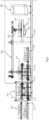
- a meat product production process 1 the major stages of a meat product production process 1 are as follows:
- the meat processing steps are implemented by an apparatus including apparatus as described below.
- a scanner 230, see below
- scanning with an X-ray source for emitting X-rays, an X-ray detector for detecting the emitted X-rays and a processor for converting them into electrical signals which are processed by digital data processors.
- the apparatus (or "production plant") is arranged to continuously supply the scanner with unscanned objects (anatomical parts) in the carriers and to remove the carriers from it and convey them back to the downstream stage 7.
- the various arrows indicated by the legend show that there are major data flows for optimization of the overall process. These include scanning data being processed by a server (local and/or cloudbased) to digitize the supply chain. This provides to the animal producer quantified data concerning applicable aspects such as quantity and distribution of lean, fat and bone proportion by weight. animal value and key morphological features (for example, rib-eye size, back fat depth). This information is of benefit to the producer as feedback for improvement in breeding and management of livestock. There is also considerable feedforward information to assist with trimming and boning. This feedforward data is in the form of numerical data outputs, three-dimensional (3D) contour maps and virtual butchering data. This drives production planning & sorting decisions, setting of production butchery targets to control processes, automated/robotic trimming/boning, and also interface instructions to operators for manual trimming, boning and packing throughout the butchery process.
- 3D three-dimensional
- a jig 100 is used at an early stage of the process when a carcass is taken from chilling.
- the jig has an elongate light-weight, solid or tubular body 101, forward members 102, 103 and 104, and also rear-facing members 105 and 106.
- the operator applies the jig to precise locations on the carcass so that the blades 102 and 104 define the longitudinal limits of a carrier (150, see below) for the scanner.
- the carcass is marked using a knife using the members 102-106 for guidance so that the carcass can be cut to the maximum length.
- the member 103 indicates location for a rump quarter portion cut.
- the members 105 and 106 indicate and mark positions for loin tail length.
- the carcass preparation involves cutting at the locations indicated by the jig 100 so that all important anatomical parts are selected and then provided for optimum placement in a carrier for CT scanning.
- the locations and dimensions of the jig ore only given by way of example, and may be of any desired configuration to suit the nature of the carcasses and dimensions of the carrier.
- lamb carcasses are analyzed whole, while beef carcasses are cut according to marking done with assistance of the jig 100.
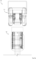
- an anatomical part carrier 150 comprises an open rectangular box shell 151 and an insert 152.
- the insert 152 fits with a friction fit with or without location dowels in the shell 151, in a manner which allows easy insertion and removal of the insert 152, for interchangeability.
- the insert 152 is configured with a curved internal profile for support of the anatomical part in a manner which does not allow movement during scanning, and also provides the desired orientation for optimum signal/noise ratio scanning, minimum scan artifacts and simpler software reconstruction and image manipulation.
- the material of the shell 151 and of the insert 152 are strong, smooth, chemically corrosionresistant, abrasion-resistant with a low XRAY absorptive capacity, such as monomer or co-polymer plastics.
- Preferred examples are PE (Polyethylene), PP (Polypropylene), APET ((Amorphous-polyethylene terephthalate), CPET (Crystalline Polyethylene Terephthalate), PTFE (Polytetrafluoroethylene), PET (polyethylene terephthalate), or HDPE (high-density polyethylene).
- the shell 151 be of high-density polyethylene (HDPE), and that the insert is also of HDPE.
- the dimensions are 350mm high, 660mm wide and 1390 long.
- the material may be clear, translucent or opaque.
- the parts have smooth surfaces with no protrusion to meat trap contamination spaces.
- the carrier allows very efficient loading of the parts for inspection and also very accurate inspection in a repeatable manner. Also, the carriers 150 may be easily re-configured by replacement of the inserts 152 as applicable for the anatomical parts to be analyzed according to production requirements.
- the carrier inserts 152 may be configured to contain more than one piece of meat in a precise orientation with optimum use of space to maximize system capacity while transferring through the CT scanning aperture. This is illustrated in Fig. 3(b) .
- the carrier handling is in-line in the longitudinal and vertical directions only, however as set out in a different section of the description below it may be in all three dimensions X, Y, and Z.
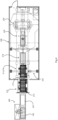
- the robotic gripper 250 comprises an overhead carriage 251 which runs on the gantry 245 in the longitudinal direction from the interlock stage 210 to the scanner 230.
- the robotic gripper 250 also comprises a housing 252 below the carriage 251, containing electric actuator or other actuators (for example pneumatically-controller, but preferably electrical) for lowering/raising the gripper 250 vertically (Z axis).
- the gantry is driven by a motor on the gantry at one end by a power train which is in this example a belt and sprocket drive, but in other examples may be a ball lead screw, a rack and pinion, and providing upper structural support for the downwardly-depending components. It supports a cross beam 260, at each end of which there are downwardly depending vertical arms 261 and 262, these three components defining a zone within which carriers are received.
- each arm 261 and 262 there is an L-shaped (in cross-section) elongate seat member 254.
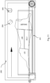
- the seat members 254 face each other and are moved in opposing manner to converge towards a carrier 150, as best shown in Fig. 7(b) .
- This drawing shows the seat members 254 at both the retracted positions and the extended carrier-engaging positions, driven by pneumatic drives 255 (which may alternatively be hydraulic, electrical).
- the pneumatic actuators 255 move pistons 272 attached to the members 254, the connection being at a vertical flange 270 from which extends a horizontal ledge 271 for engaging the underneath edge of a carrier 150. This arrangement achieves a pick-up point of least movement, deformation and stress on the carrier 150.
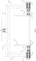
- a system controller (not shown) operates so that the receiver 253 acts in a passive manner, with the carrier 150 being moved in the longitudinal direction into the space within the receiver 253 by the powered couch 240 or powered carrier belt 215.
- the powered couch 240 receives the carrier from the interlock upper conveyor 215, and another is the scanner couch 240 which moves the carrier out from the scanner 230 into position within the awaiting receiver 253.
- the couch 240 has an innovative upper board 280 with a flat carrier-supporting surface 282, and a pair of lateral rims 281 for retaining the carrier laterally in the couch 240.
- the width of the board 280 is less than the carrier width so as to leave space for access by the opposed seat members 254 of the gripper 250 to carriers.
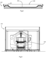
- the scanner 230 is shown in front view in Fig. 9 , the couch 240 being aligned with the scanner's tunnel.
- the scanner is of the type which has only one entry and exit port for the object being analyzed.
- the CT scanner technology has developed over the years with this as the established arrangement, primarily for medical use.
- the invention is able to avail of such an established arrangement despite the fact that the application is industrial, with a much higher throughput than is the situation for medical examination. This has been achieved by the carrierhandling components described above.
- the carrier is loaded by being placed on the dead roller conveyor 199 from where it is slid onto the upper conveyor 200 to avoid damage to the upper conveyor 200 and product movement.
- the top conveyor 201 of the preparation stage 200 is aligned with the top conveyor 211 of the interlock zone 210.
- S2 Movement into the interlock zone top level 211, with opening of the outer door 213 while the inner door 214 is closed.
- S3 From the interlock zone 210 with closing of the outer door 213, movement of the conveyors 211 and 215, and opening of the inner door 214.
- S6 Downward movement of the platform 218 under action of the scissors jack.
- the combination of the gripper 250 and the platform 218 mean that there is relatively little requirement for overhead height for equipment above the top position of the gripper. This also minimizes cycle time, maximizes capacity, and minimizes enclosure height.
- S7 Movement longitudinally, by rotation of the conveyor belt at the lower level height, towards the interlock zone 210.
- S8 Movement into the interlock zone 210 lower level 212, with opening of the inner door 214 while the outer door 213 is closed. This step is preferably synchronized with the step S3.
- S9 Delivery from the interlock zone 210, with opening of the outer door 213 while the inner door 214 is closed.
- the carcass may be post rigor or pre rigor.
- the anatomical parts are preferably placed on the carriers according to a scheme to optimize or modulate the flow rate of meat volume into the scanner. For example, this scheme may alternate larger and smaller sizes of anatomical parts placed on successive carriers for entry to the port.
- the carcasses are preferably delivered to the port on a support such as a hanger which has an identifier, the carrier is marked with the same identifier, and there is matching of the anatomical parts with the originating support after exit from the port for traceability.
- the carrier 150 is seated, for entry to the scanner, on the loading conveyor 240, which has the board 280 which has a substantially planar base and a raised edge, allowing convenient gripping by the robotic gripper 250, shown in Fig. 7 .
- the gripper 250 awaits movement of the carrier 150 into its volume with the gripper seats members 254 moving inwardly so that they underlie the carrier 150 and so grip it so that it can be moved according to S5.
- the gripper 250 is passive until the carrier 150 is moved into its zone for commencement of the movement S4.
- the scanner chamber 300 in maintained shielded for radiation safety, and for optimum scanner operation the environment is maintained at preferably 10°C to 22°C.
- the system has an automatic control circuit to automatically start and automatically remote reset the CT scanner after a set number of scans.
- the CT scanner 230 has tube cooling for the high-throughput use, power modulation, and a fast return stroke, CT scan occurs under conditions to optimize image quality, tube life, and safety (80-140kV, 10-800mA, 10-20secs. 800mm maximum width tunnel & field of view).
- CT power is modulated during a CT scan based on meat profile and length automatically inputted during S1 using an incoming pre-scan inspection station with an inspection controller.
- this is located before the stage 200 as there is more available space and the inspection can be done as part of loading the carriers and conveying them towards the interlock port 210.
- the inspection station can be located at any desired position before the scanner, including immediately before the scanner as the carriers are loaded onto the scanner couch.
- the inspection station includes a belt conveyor 201, and a position encoder.
- a carrier with orientated meat piece(s) inside is routed through the inspection station, which detects a meat profile with use of an overhead laser line sensor 283 coupled with offset digital color camera 284, mounted on a food grade frame 285, and a controller with interpretation software.
- the pre-scan inspection controller issues commands to the CT scanner controller for that particular item of meat as it is subsequently scanned on a first- in- first- out (FIFO) basis.
- FIFO first- in- first- out
- the software eliminates (crops) the images relating to the carrier alone.
- This data is interpreted by an algorithm which changes CT scanner voltage and current to compensate for different product depth and volume so as to minimize degradation of the XRAY tube and detector. For example, depths beyond 200mm might necessitate parameter changes from 80kV/30mA to 130kV/300mA for a defined length along the meat. Scanning is automatically stopped when the meat overall length is exceeded.
- meat parts are introduced into the scanner in a sequence to facilitate tube cooling. For example, in one scheme long, deep meat pieces are immediately followed by shorter shallow meat pieces from the same or different animals. This gives time in cycles for the scanner tube to cool down and not reach maximum allowable heat dissipation (which may in extreme cases trigger shutdown).
- Conditioned air (temperature 10°C, 20% RH, 1m/s flow rate) is provided to assist tube cooling without electronic damage.
- the pre-scan inspection station may be located elsewhere, including immediately before the scanner. In the latter case there is the benefit of real time power control of the scanner according to the individual carrier, and this may be reliably achieved because it is immediately correlated to the carrier being introduced. However, it would be more difficult to manage inter-carrier flows, to for example introduce to the scanner a carrier with a small quantity of meat following a carrier with a large quantity of meat.
- the optimization of the scanner is achieved by one or both of:
- first gripper for picking a carrier from a first location (for example 215) and placing it onto the scanner couch (240), and a second gripper for picking a carrier from the couch and placing it at a second location (for example 218) so as to increase capacity and reduce cycle time.
- the first gripper and the second gripper may move along a common axis in one example, preferably synchronously along the common axis which can be parallel or orthogonal or at an oblique angle to the direction of carrier travel through the scanner.
- the axis along which the first gripper and second gripper are moved may be substantially parallel or perpendicular or oblique to the movement of the table into and out of the scanner.
- a third gripper 250 for picking a carrier 150 from a third location (e.g. 215a) and placing it onto the scanner table ("couch") 240.
- a fourth gripper 250 for picking a carrier from the couch 240 and placing it at a fourth location such as conveyor 218a on the opposed side of the scanner, as shown in Fig. 12 .
- the handling components may be arranged to move the third and the fourth grippers 250 synchronously along a further common axis, which axis may be substantially perpendicular or parallel or oblique to the movement of the table into and out of the scanner.
- These arrangements may provide for the carriers 150 to enter the gantry from one lateral side with respect to the scanner longitudinal axis and to exit the gantry at the opposite side so as to increase system capacity by scanning a new carrier 150 during each stroke of the couch 240.
- the pick and place robotic gantry is a modified form of the gantry 245, having X, Y & Z axis articulation and may include rotational movements on one or more of the X, Y, and Z axes.
- the chamber which protects humans from radiation encompasses only the X-ray source, the X-ray detector, and the table locally at the scanner without also encompassing the arrangement suitable for supplying the scanner couch 240 with unscanned objects and removing scanned objects from it.
- the first gripper 250 picks a carrier 150 with a yet unscanned object from a first location.
- the second gripper 250 is still empty, i.e. it does not carry any carrier.
- step b) the first gripper 250 and the second gripper 250 move along a common axis until the first gripper 250 with the carrier 150 carrying the yet unscanned object reaches the table 240. Subsequently, the carrier 150 is lowered down onto the table 240 and the first gripper 250 releases the carrier 150.
- step c) the table 240 with the carrier 150 moves through the gantry of the scanner.
- a CT scan of the object is performed.
- the carrier 150 is shown once it has already travelled through the scanner 230. While the object travels through the scanner 230, the first and second gripper 250 move back to their initial positions along their common axis.
- step d) the first gripper 250 picks another carrier 150 with a yet unscanned object from the first location.
- the carrier 150 with the scanned object travels back through the scanner 230 and is subsequently picked by the second gripper 250.
- the object may be scanned a second time while travelling back through the scanner 230 or it may not be scanned.
- step e) the first gripper 250 and the second gripper 250 move along a common axis until the first gripper 250 with the carrier 150 carrying the yet unscanned object reaches the table 240. Subsequently, the carrier 150 is lowered down onto the table and the first gripper 250 releases the carrier 150. Note that at the same time, the second gripper 250 with the carrier 150 carrying the scanned object reaches a second location.
- step f) the carrier 150 with the scanned object is released from the second gripper 250. It will be transported to the unloading station. At the same time, the table with the other carrier 150 moves through the gantry of the scanner 230. A CT scan of the object is performed. Thus, as in step f) the carrier 150 is shown once it has already travelled through the scanner 230, the carrier 150 carries a scanned object.
- step g) the first and second gripper 250 move back to their initial positions along their common axis.
- the carrier 150 with the scanned object travels back through the scanner 230.
- it can now already be picked by the second gripper 250.
- the object may be scanned a second time while travelling back through the scanner 230 or it may not be scanned.
- step h the first gripper 250 picks another carrier 150 with a yet unscanned object from the first location.
- the carrier 150 with the scanned object has not already been picked by the second gripper 150 in step g), it needs to be picked now.
- step i) the first gripper 250 and the second gripper 250 move along a common axis in the direction denoted by the respective arrow pointing downwards. They move as far until the first gripper 250 with the carrier 150 carrying the yet unscanned object reaches the table. Subsequently, the carrier 150 is lowered down onto the table and the first gripper 250 releases the carrier 150. Note that at the same time, the second gripper 250 with the carrier 150 carrying the scanned object reaches a second location.
- the steps f) to i) are preferably repeated continuously for two or more cycles.
- a quasi-continuous scanning of objects is achieved leading to a high throughput.
- a conventional CT scanning unit can be used including a (patient) table, i.e. without major modifications as it would be the case if the objects would cross the scanning unit on a conveyor belt.
- the only substantial modifications comprise adding the first and second gripper and means for moving them along a common axis.
- the jig 100 to ensure accurate break up and length for fitting in the carrier 150 and scanning.
- Profile detection system for power modulation This arises from planning of inlet of parts to the interlock zone, smaller parts being followed by larger parts in an optimum pattern for optimum modulation of power of the scanner 130.
- interlock shutter doors 213 and 214 The interlock shutter doors 213 and 214, gentle index conveyors 211/212 and 215/216, scissor lift platform 218, and the passive gripper 250.
- Adjustable height frame with skirts to reduce lead in floor
- Target benchmark for downstream processing e.g. % bone in deboning rooms.
- Handling system facilitates the actioning of decisions through linking each meat piece to an animal to a specific operator & transmitting relevant instructions to said operator.
- the manner in which the scanner is modified in real time helps to achieve optimum utilization and reliability of the scanner equipment. This real time control is achieved with use of relatively simple and inexpensive items of equipment for the inspection station.
- CT computed tomography
- MRI Magnetic Resonance Imaging
Landscapes
- Engineering & Computer Science (AREA)
- Life Sciences & Earth Sciences (AREA)
- Food Science & Technology (AREA)
- Wood Science & Technology (AREA)
- Zoology (AREA)
- Biophysics (AREA)
- Robotics (AREA)
- Mechanical Engineering (AREA)
- Computer Vision & Pattern Recognition (AREA)
- Analysing Materials By The Use Of Radiation (AREA)
- Processing Of Meat And Fish (AREA)
- General Preparation And Processing Of Foods (AREA)
Claims (15)
- Appareil de transformation de la viande comprenant une étape d'analyse automatisée comprenant :une chambre protégée contre les rayonnements (300),un scanner de tomographie (230) doté d'un dispositif de commande de scanner, et agencé pour réaliser une analyse de morceaux de viande,un processeur de données numérique lié au scanner pour un traitement de données de balayage et une fourniture de sorties,caractérisé en ce que l'appareil comprend en outre :un port (210) pour une entrée et une sortie de morceaux de viande placés dans des éléments de transport (150) dans et hors de la chambre pour une analyse par le scanner, ledit port comprenant une chambre de verrouillage (210), présentant une porte interne (214) et une porte externe (213) et un dispositif de commande de port pour assurer que seule une porte peut être ouverte lors du fonctionnement du scanner, etun système de manutention (245, 250) pour un déplacement automatisé des éléments de transport entre le port (210) et le scanner (230), et un dispositif de commande de système de manutention pour le système de manutention,dans lequel ledit processeur est configuré pour fournir des données de retour sur une qualité de viande déterminée par balayage, et pour acheminer lesdites données de retour vers des fournisseurs ; et pour fournir des données prédictives à des étapes de transformation en aval pour un désossage et/ou un parage optimisé.
- Appareil de transformation de la viande selon la revendication 1, dans lequel la chambre de verrouillage présente un niveau supérieur de convoyeur (211) et un niveau inférieur de convoyeur (212), un pour une entrée et un pour une sortie d'éléments de transport avant et après analyse.
- Appareil de transformation de la viande selon les revendications 1 ou 2, dans lequel le système de manutention comprend un portique (245) et une pluralité de préhenseurs robotiques (250) agencés pour se déplacer sur le portique dans au moins une direction longitudinale entre le port et le scanner, et comprenant un receveur de préhenseur (253) servant à recevoir et entrer en prise avec un élément de transport pour un morceau de viande destiné à être analysé.
- Appareil de transformation de la viande selon une quelconque revendication précédente, dans lequel le système de manutention comprend une plateforme verticalement mobile (218) qui est mobile entre une position supérieure pour recevoir un élément de transport à partir du préhenseur robotique (250) et une position inférieure pour une délivrance de l'élément de transport dans le port (210).
- Appareil de transformation de la viande selon une quelconque revendication précédente, dans lequel le scanner comprend un convoyeur de chargement (240) présentant un lit (280) avec une surface plane plate (282) pour un support d'un élément de transport tout en permettant un accès par le préhenseur pour venir en prise avec l'élément de transport (150).
- Appareil de transformation de la viande selon une quelconque revendication précédente, dans lequel au moins certains des éléments de transport comprennent une coque à sommet ouvert (151) et un insert (152) configuré pour s'ajuster sans mouvement relatif significatif dans la coque et pour supporter un morceau de viande à une orientation souhaitée ; et dans lequel l'insert (152) comprend des parois internes inclinées formant un siège pour un morceau de viande avec une orientation stable.
- Appareil de transformation de la viande selon la revendication 6, dans lequel la coque et l'insert sont chacun d'un matériau résistant à la corrosion chimique et résistant à l'abrasion avec une faible capacité d'absorption de rayons X, et dans lequel la coque et/ou l'insert comprennent chacun un ou plusieurs éléments choisis parmi le PE (polyéthylène), le PP (polypropylène), l'APET (polyéthylène téréphtalate amorphe), le CPET (polyéthylène téréphtalate cristallin), le PTFE (polytétrafluoroéthylène), le PET (polyéthylène téréphtalate) ou le HDPE (polyéthylène haute densité).
- Appareil de transformation de la viande selon une quelconque revendication précédente, comprenant en outre un gabarit (100) présentant un corps allongé (101) et des éléments tels que des broches ou des lames (102-106) faisant saillie à partir du corps pour aider au marquage d'une carcasse à un emplacement souhaité pour réaliser une découpe pour un ajustement dans un élément de transport.
- Appareil de transformation de la viande selon une quelconque revendication précédente, dans lequel l'appareil comprend en outre une station d'inspection pré-balayage (283-285) avec un ou plusieurs capteurs et agencée pour détecter un volume et/ou une densité de morceaux de viande anatomiques sur un élément de transport, et un dispositif de commande d'inspection configuré pour alimenter des données correspondantes au dispositif de commande de scanner (230), dans lequel le dispositif de commande de scanner est configuré pour modifier un fonctionnement de scanner selon lesdites données d'inspection, et dans lequel le dispositif de commande de scanner est configuré pour changer une tension et/ou un courant de scanner pour compenser des différences de profondeur et/ou de volume de morceaux de viande anatomiques ou d'artéfacts de produits afin de minimiser une dégradation du scanner.
- Appareil de transformation de la viande selon la revendication 9, dans lequel le capteur comprend un scanner à ligne lumineuse (283), une caméra numérique couleur (284), et un dispositif de commande d'inspection configuré pour générer et transmettre des commandes au scanner.
- Appareil de transformation de la viande selon la revendication 10, dans lequel le dispositif de commande d'inspection est configuré pour enregistrer une déviation d'une ligne lumineuse structurée lorsqu'un élément de transport (150) se déplace à travers la station d'inspection, et pour interpréter la déviation de ligne comme un indicateur d'un changement de profondeur et de volume de viande couplée à sa position linéaire relative à un point fixe sur l'élément de transport.
- Appareil de transformation de la viande selon la revendication 11, dans lequel le dispositif de commande d'inspection est configuré pour interpréter un retour de la ligne à sa forme d'origine comme une indication du point d'extrémité du morceau de viande, et pour l'enregistrer de préférence à titre de position X horizontale.
- Procédé de fonctionnement d'un appareil selon une quelconque revendication précédente, le procédé comprenant les étapes de placement de morceaux de viande anatomiques dans les éléments de transport, de commande du système de manutention pour acheminer les éléments de transport dans et à travers le port, vers le scanner, dans le scanner, hors du scanner, à nouveau vers le port, et hors du port pour sortir de la chambre, dans lequel les morceaux de viande anatomiques sont placés dans les éléments de transport de manière stable, soit sous la forme de carcasse entière soit d'un ou de plusieurs morceaux d'une carcasse plus grande.
- Procédé selon la revendication 13, dans lequel les morceaux de viande sont inspectés automatiquement par une station d'inspection et un dispositif de commande de la station d'inspection transmet vers l'avant des données qui sont utilisées par le dispositif de commande de scanner pour commander un fonctionnement de scanner selon des attributs physiques de morceaux de viande, et dans lequel l'appareil comprend un gabarit (100) présentant un corps allongé (101) et des éléments tels que des broches ou des lames (102-106) faisant saillie à partir du corps, et le procédé comprend les étapes d'application du gabarit à une carcasse et les éléments du gabarit indiquant des emplacements pour des découpes sur la longueur totale de la carcasse pour s'ajuster dans un élément de transport et/ou pour aider au marquage d'une carcasse à un emplacement souhaité pour une découpe permettant un ajustement dans un élément de transport, et éventuellement, dans lequel les morceaux de viande anatomiques sont placés sur les éléments de transport selon un schéma pour optimiser ou moduler le débit de volume de viande dans le scanner.
- Procédé selon une des revendications 13 ou 14, dans lequel le système de manutention comprend un portique (245) et une pluralité de préhenseurs robotiques (250) agencés pour se déplacer sur le portique dans au moins une direction longitudinale entre le port et le scanner, et comprenant un receveur de préhenseur (253) pour recevoir et entrer en prise avec un élément de transport pour un morceau de viande destiné à être analysé, et dans lequel le dispositif de commande d'inspection et le dispositif de commande de scanner réalisent une optimisation d'un scanner au moyen d'une ou des deux parmi :une commande intra élément de transport, dans laquelle le scanner modifie sa consommation de puissance en temps réel pendant un balayage du ou des morceaux de viande dans un unique élément de transport particulier, en utilisant plus de puissance lorsqu'il y a la densité et/ou le volume le plus important dans le morceau de viande en cours de balayage, etune commande inter éléments de transport, dans laquelle les éléments de transport sont alimentés dans le scanner selon une séquence qui aide à éviter une surchauffe et atteindre une bonne fiabilité, des morceaux anatomiques petits, moyens, et grands étant délivrés au scanner selon un schéma souhaité pour une optimisation de la consommation de puissance de scanner et d'autres paramètres de scanner.
Applications Claiming Priority (3)
| Application Number | Priority Date | Filing Date | Title |
|---|---|---|---|
| EP19218659.1A EP3837981B1 (fr) | 2019-12-20 | 2019-12-20 | Procédé et appareil de traitement de la viande |
| EP19218654.2A EP3837980B1 (fr) | 2019-12-20 | 2019-12-20 | Procédé et appareil de traitement de la viande |
| PCT/EP2020/085389 WO2021122247A1 (fr) | 2019-12-20 | 2020-12-09 | Procédé et appareil de traitement de viande |
Publications (3)
| Publication Number | Publication Date |
|---|---|
| EP4075987A1 EP4075987A1 (fr) | 2022-10-26 |
| EP4075987B1 true EP4075987B1 (fr) | 2024-01-03 |
| EP4075987C0 EP4075987C0 (fr) | 2024-01-03 |
Family
ID=73695069
Family Applications (1)
| Application Number | Title | Priority Date | Filing Date |
|---|---|---|---|
| EP20817444.1A Active EP4075987B1 (fr) | 2019-12-20 | 2020-12-09 | Procédé et appareil de traitement de la viande |
Country Status (6)
| Country | Link |
|---|---|
| US (1) | US12108768B2 (fr) |
| EP (1) | EP4075987B1 (fr) |
| AU (1) | AU2020405854A1 (fr) |
| BR (1) | BR112022012211A2 (fr) |
| PL (1) | PL4075987T3 (fr) |
| WO (1) | WO2021122247A1 (fr) |
Family Cites Families (15)
| Publication number | Priority date | Publication date | Assignee | Title |
|---|---|---|---|---|
| GB9013983D0 (en) | 1990-06-22 | 1990-08-15 | Nat Res Dev | Automatic carcass grading apparatus and method |
| US5937080A (en) * | 1997-01-24 | 1999-08-10 | Design Systems, Inc. | Computer controlled method and apparatus for meat slabbing |
| ATE266199T1 (de) | 1999-10-21 | 2004-05-15 | Foss Analytical As | Verfahren und vorrichtung zur bestimmung der eigenschaften von lebensmitteln oder tierfutter |
| NZ550406A (en) | 2004-03-19 | 2010-04-30 | Marel Hf | X-ray apparatus for inspecting food items that have been formed to a uniform thickness to detect the nature, quantity, and location of undesired foreign material within the food item |
| DE102004047773A1 (de) | 2004-09-27 | 2006-04-06 | Horst Eger | Verfahren zur Bestimmung physiologischer Grössen eines Schlachttierkörpers |
| DK1887874T3 (da) | 2005-05-31 | 2012-10-15 | Teknologisk Inst | Fremgangsmåde og anvendelse af en database til automatisk at bestemme kvalitetskarakteristika for en slagtekrop i en slagtelinje |
| DE102006032423B4 (de) | 2006-07-13 | 2008-04-24 | Delipetkos, Elias, Dipl.-Inform. (FH) | Verfahren und Vorrichtung zur Bestimmung des Fettgehaltes einer Gesamtheit von Fleischstücken |
| RU2628400C1 (ru) | 2013-07-11 | 2017-08-16 | ФОСС Аналитикал А/С | Мясоперерабатывающее устройство, содержащее рентгеновский анализатор |
| US9778651B2 (en) * | 2014-01-22 | 2017-10-03 | John Bean Technologies Corporation | System for cutting and unloading portions |
| AU2014392651B2 (en) | 2014-05-02 | 2018-03-22 | Invention Development Management Company, Llc | Meat assessment device |
| CN105651776A (zh) | 2015-12-30 | 2016-06-08 | 中国农业大学 | 基于计算机视觉的牛胴体产肉量自动分级装置与方法 |
| EP3451840A1 (fr) | 2016-05-03 | 2019-03-13 | Teknologisk Institut | Tomodensitomètre avec de grands pixels de détecteur et/ou une conception hygiénique pour balayage continu |
| WO2017191162A1 (fr) | 2016-05-03 | 2017-11-09 | Teknologisk Institut | Tomodensitomètre à pixels de détecteur larges et/ou conception hygiénique pour balayage continu |
| WO2018085879A1 (fr) | 2016-11-09 | 2018-05-17 | Scott Automation & Robotics Pty Ltd | Système et procédé de traitement de carcasse |
| WO2021154566A1 (fr) * | 2020-01-27 | 2021-08-05 | John Bean Technologies Corporation | Taille de produits de travail pour optimiser le pressage |
-
2020
- 2020-12-09 BR BR112022012211A patent/BR112022012211A2/pt unknown
- 2020-12-09 PL PL20817444.1T patent/PL4075987T3/pl unknown
- 2020-12-09 WO PCT/EP2020/085389 patent/WO2021122247A1/fr unknown
- 2020-12-09 EP EP20817444.1A patent/EP4075987B1/fr active Active
- 2020-12-09 US US17/786,560 patent/US12108768B2/en active Active
- 2020-12-09 AU AU2020405854A patent/AU2020405854A1/en active Pending
Also Published As
| Publication number | Publication date |
|---|---|
| EP4075987A1 (fr) | 2022-10-26 |
| AU2020405854A1 (en) | 2022-07-07 |
| US20230022593A1 (en) | 2023-01-26 |
| US12108768B2 (en) | 2024-10-08 |
| PL4075987T3 (pl) | 2024-04-29 |
| EP4075987C0 (fr) | 2024-01-03 |
| WO2021122247A1 (fr) | 2021-06-24 |
| BR112022012211A2 (pt) | 2022-09-13 |
Similar Documents
| Publication | Publication Date | Title |
|---|---|---|
| EP2531038B1 (fr) | Appareil de traitement d'aliments pour détecter et couper des tissus durs des produits alimentaires | |
| JP6903085B2 (ja) | 豚や牛や羊や山羊といった屠殺された動物の屠殺体の一部を処理するためのシステムおよび方法、ならびに屠殺された豚の脚を運搬するための搬送デバイス | |
| US11266156B2 (en) | Portioning/trimming of rib primal cuts | |
| CA2676506C (fr) | Procede et systeme de traitement d'articles | |
| WO2021030321A1 (fr) | Systèmes et procédés d'utilisation d'imagerie à rayons x tridimensionnelle dans des applications de production et de transformation de viande | |
| US8661773B2 (en) | Meat packaging | |
| CN115379761A (zh) | 动物尸体的自动化移除 | |
| CN111296539A (zh) | 羊胴体机器人自主分割方法及系统 | |
| US20220289416A1 (en) | A method and an apparatus for filling containers with food items | |
| US20180242602A1 (en) | Method and apparatus for deshelling shellfish | |
| EP4075987B1 (fr) | Procédé et appareil de traitement de la viande | |
| EP3837980B1 (fr) | Procédé et appareil de traitement de la viande | |
| EP3837981B1 (fr) | Procédé et appareil de traitement de la viande | |
| EP2946667B1 (fr) | Appareil d'imagerie à rayons x pour la détermination d'une trajectoire de coupe d'une carcasse et procédé correspondant | |
| DK202000212A1 (en) | Automatic determination of the presence and subsequent removal of bones in meat products | |
| Sørensen et al. | Automation in the production of pork meat | |
| WO2020120566A1 (fr) | Système de gestion d'aliments | |
| CA3060072A1 (fr) | Systeme et methode d'exploitation d'une installation d'etourdissement de la volaille |
Legal Events
| Date | Code | Title | Description |
|---|---|---|---|
| STAA | Information on the status of an ep patent application or granted ep patent |
Free format text: STATUS: UNKNOWN |
|
| STAA | Information on the status of an ep patent application or granted ep patent |
Free format text: STATUS: THE INTERNATIONAL PUBLICATION HAS BEEN MADE |
|
| PUAI | Public reference made under article 153(3) epc to a published international application that has entered the european phase |
Free format text: ORIGINAL CODE: 0009012 |
|
| STAA | Information on the status of an ep patent application or granted ep patent |
Free format text: STATUS: REQUEST FOR EXAMINATION WAS MADE |
|
| 17P | Request for examination filed |
Effective date: 20220615 |
|
| AK | Designated contracting states |
Kind code of ref document: A1 Designated state(s): AL AT BE BG CH CY CZ DE DK EE ES FI FR GB GR HR HU IE IS IT LI LT LU LV MC MK MT NL NO PL PT RO RS SE SI SK SM TR |
|
| DAV | Request for validation of the european patent (deleted) | ||
| DAX | Request for extension of the european patent (deleted) | ||
| GRAP | Despatch of communication of intention to grant a patent |
Free format text: ORIGINAL CODE: EPIDOSNIGR1 |
|
| STAA | Information on the status of an ep patent application or granted ep patent |
Free format text: STATUS: GRANT OF PATENT IS INTENDED |
|
| INTG | Intention to grant announced |
Effective date: 20231009 |
|
| GRAS | Grant fee paid |
Free format text: ORIGINAL CODE: EPIDOSNIGR3 |
|
| GRAA | (expected) grant |
Free format text: ORIGINAL CODE: 0009210 |
|
| STAA | Information on the status of an ep patent application or granted ep patent |
Free format text: STATUS: THE PATENT HAS BEEN GRANTED |
|
| AK | Designated contracting states |
Kind code of ref document: B1 Designated state(s): AL AT BE BG CH CY CZ DE DK EE ES FI FR GB GR HR HU IE IS IT LI LT LU LV MC MK MT NL NO PL PT RO RS SE SI SK SM TR |
|
| REG | Reference to a national code |
Ref country code: GB Ref legal event code: FG4D |
|
| REG | Reference to a national code |
Ref country code: CH Ref legal event code: EP |
|
| REG | Reference to a national code |
Ref country code: DE Ref legal event code: R096 Ref document number: 602020023971 Country of ref document: DE |
|
| REG | Reference to a national code |
Ref country code: IE Ref legal event code: FG4D |
|
| U01 | Request for unitary effect filed |
Effective date: 20240105 |
|
| U07 | Unitary effect registered |
Designated state(s): AT BE BG DE DK EE FI FR IT LT LU LV MT NL PT SE SI Effective date: 20240116 |
|
| PG25 | Lapsed in a contracting state [announced via postgrant information from national office to epo] |
Ref country code: ES Free format text: LAPSE BECAUSE OF FAILURE TO SUBMIT A TRANSLATION OF THE DESCRIPTION OR TO PAY THE FEE WITHIN THE PRESCRIBED TIME-LIMIT Effective date: 20240103 |
|
| PG25 | Lapsed in a contracting state [announced via postgrant information from national office to epo] |
Ref country code: ES Free format text: LAPSE BECAUSE OF FAILURE TO SUBMIT A TRANSLATION OF THE DESCRIPTION OR TO PAY THE FEE WITHIN THE PRESCRIBED TIME-LIMIT Effective date: 20240103 |
|
| PG25 | Lapsed in a contracting state [announced via postgrant information from national office to epo] |
Ref country code: IS Free format text: LAPSE BECAUSE OF FAILURE TO SUBMIT A TRANSLATION OF THE DESCRIPTION OR TO PAY THE FEE WITHIN THE PRESCRIBED TIME-LIMIT Effective date: 20240503 |
|
| PG25 | Lapsed in a contracting state [announced via postgrant information from national office to epo] |
Ref country code: GR Free format text: LAPSE BECAUSE OF FAILURE TO SUBMIT A TRANSLATION OF THE DESCRIPTION OR TO PAY THE FEE WITHIN THE PRESCRIBED TIME-LIMIT Effective date: 20240404 |
|
| PG25 | Lapsed in a contracting state [announced via postgrant information from national office to epo] |
Ref country code: RS Free format text: LAPSE BECAUSE OF FAILURE TO SUBMIT A TRANSLATION OF THE DESCRIPTION OR TO PAY THE FEE WITHIN THE PRESCRIBED TIME-LIMIT Effective date: 20240403 Ref country code: HR Free format text: LAPSE BECAUSE OF FAILURE TO SUBMIT A TRANSLATION OF THE DESCRIPTION OR TO PAY THE FEE WITHIN THE PRESCRIBED TIME-LIMIT Effective date: 20240103 |
|
| PG25 | Lapsed in a contracting state [announced via postgrant information from national office to epo] |
Ref country code: CZ Free format text: LAPSE BECAUSE OF FAILURE TO SUBMIT A TRANSLATION OF THE DESCRIPTION OR TO PAY THE FEE WITHIN THE PRESCRIBED TIME-LIMIT Effective date: 20240103 |
|
| PG25 | Lapsed in a contracting state [announced via postgrant information from national office to epo] |
Ref country code: RS Free format text: LAPSE BECAUSE OF FAILURE TO SUBMIT A TRANSLATION OF THE DESCRIPTION OR TO PAY THE FEE WITHIN THE PRESCRIBED TIME-LIMIT Effective date: 20240403 Ref country code: NO Free format text: LAPSE BECAUSE OF FAILURE TO SUBMIT A TRANSLATION OF THE DESCRIPTION OR TO PAY THE FEE WITHIN THE PRESCRIBED TIME-LIMIT Effective date: 20240403 Ref country code: IS Free format text: LAPSE BECAUSE OF FAILURE TO SUBMIT A TRANSLATION OF THE DESCRIPTION OR TO PAY THE FEE WITHIN THE PRESCRIBED TIME-LIMIT Effective date: 20240503 Ref country code: HR Free format text: LAPSE BECAUSE OF FAILURE TO SUBMIT A TRANSLATION OF THE DESCRIPTION OR TO PAY THE FEE WITHIN THE PRESCRIBED TIME-LIMIT Effective date: 20240103 Ref country code: GR Free format text: LAPSE BECAUSE OF FAILURE TO SUBMIT A TRANSLATION OF THE DESCRIPTION OR TO PAY THE FEE WITHIN THE PRESCRIBED TIME-LIMIT Effective date: 20240404 Ref country code: CZ Free format text: LAPSE BECAUSE OF FAILURE TO SUBMIT A TRANSLATION OF THE DESCRIPTION OR TO PAY THE FEE WITHIN THE PRESCRIBED TIME-LIMIT Effective date: 20240103 |