EP4075784B1 - Mobile einheit, steuervorrichtung und bildgebungsverfahren - Google Patents
Mobile einheit, steuervorrichtung und bildgebungsverfahren Download PDFInfo
- Publication number
- EP4075784B1 EP4075784B1 EP20899530.8A EP20899530A EP4075784B1 EP 4075784 B1 EP4075784 B1 EP 4075784B1 EP 20899530 A EP20899530 A EP 20899530A EP 4075784 B1 EP4075784 B1 EP 4075784B1
- Authority
- EP
- European Patent Office
- Prior art keywords
- image data
- imaging
- plane
- mobile object
- distance
- Prior art date
- Legal status (The legal status is an assumption and is not a legal conclusion. Google has not performed a legal analysis and makes no representation as to the accuracy of the status listed.)
- Active
Links
Images


Classifications
-
- H—ELECTRICITY
- H04—ELECTRIC COMMUNICATION TECHNIQUE
- H04N—PICTORIAL COMMUNICATION, e.g. TELEVISION
- H04N23/00—Cameras or camera modules comprising electronic image sensors; Control thereof
- H04N23/60—Control of cameras or camera modules
-
- H—ELECTRICITY
- H04—ELECTRIC COMMUNICATION TECHNIQUE
- H04N—PICTORIAL COMMUNICATION, e.g. TELEVISION
- H04N13/00—Stereoscopic video systems; Multi-view video systems; Details thereof
- H04N13/20—Image signal generators
- H04N13/204—Image signal generators using stereoscopic image cameras
- H04N13/25—Image signal generators using stereoscopic image cameras using two or more image sensors with different characteristics other than in their location or field of view, e.g. having different resolutions or colour pickup characteristics; using image signals from one sensor to control the characteristics of another sensor
-
- H—ELECTRICITY
- H04—ELECTRIC COMMUNICATION TECHNIQUE
- H04N—PICTORIAL COMMUNICATION, e.g. TELEVISION
- H04N13/00—Stereoscopic video systems; Multi-view video systems; Details thereof
- H04N13/20—Image signal generators
- H04N13/257—Colour aspects
-
- H—ELECTRICITY
- H04—ELECTRIC COMMUNICATION TECHNIQUE
- H04N—PICTORIAL COMMUNICATION, e.g. TELEVISION
- H04N13/00—Stereoscopic video systems; Multi-view video systems; Details thereof
- H04N13/20—Image signal generators
- H04N13/286—Image signal generators having separate monoscopic and stereoscopic modes
-
- H—ELECTRICITY
- H04—ELECTRIC COMMUNICATION TECHNIQUE
- H04N—PICTORIAL COMMUNICATION, e.g. TELEVISION
- H04N5/00—Details of television systems
- H04N5/222—Studio circuitry; Studio devices; Studio equipment
-
- B—PERFORMING OPERATIONS; TRANSPORTING
- B64—AIRCRAFT; AVIATION; COSMONAUTICS
- B64U—UNMANNED AERIAL VEHICLES [UAV]; EQUIPMENT THEREFOR
- B64U10/00—Type of UAV
- B64U10/10—Rotorcrafts
- B64U10/13—Flying platforms
-
- B—PERFORMING OPERATIONS; TRANSPORTING
- B64—AIRCRAFT; AVIATION; COSMONAUTICS
- B64U—UNMANNED AERIAL VEHICLES [UAV]; EQUIPMENT THEREFOR
- B64U2101/00—UAVs specially adapted for particular uses or applications
- B64U2101/30—UAVs specially adapted for particular uses or applications for imaging, photography or videography
-
- B—PERFORMING OPERATIONS; TRANSPORTING
- B64—AIRCRAFT; AVIATION; COSMONAUTICS
- B64U—UNMANNED AERIAL VEHICLES [UAV]; EQUIPMENT THEREFOR
- B64U2201/00—UAVs characterised by their flight controls
- B64U2201/20—Remote controls
Definitions
- the present invention relates to a mobile object, a control device, and an imaging method.
- a mobile object such as a drone is provided with a camera, which is used to acquire a captured image of a structure, and a three-dimensional model is generated from the acquired captured image.
- JP2015-114954A proposes a technique for acquiring two-dimensional image data of a target object using a mobile object provided with a camera and generating a three-dimensional point group using SfM (Structure from Motion) to generate a three-dimensional model.
- SfM Structure from Motion
- the document JP6586602B1 discloses a mobile object comprising a image acquisition device and a control device according to the state of the art.
- SfM a large amount of two-dimensional image data is acquired with imaging ranges overlapped with each other, and a self-position and the coordinates of a target object are estimated to generate a three-dimensional point group of the target object. This requires processing of a large amount of two-dimensional image data and may increase the processing time.
- the present invention has been made in view of such a situation, and an object thereof is to provide a mobile object, a control device, and an imaging method that can reduce image data.
- a control device and an imaging method according to the invention are defined in the claims.
- image data can be reduced, and an increase in processing time can be avoided.
- Fig. 1 is a diagram conceptually illustrating an image processing system constituted by an image processing apparatus 300 and a mobile object 100.
- the mobile object 100 is, for example, an unmanned aerial vehicle (UAV).
- UAV unmanned aerial vehicle
- the mobile object 100 has a mobile object main body 102, propulsion units 104 included in the mobile object main body 102, and a control device 120 included in the mobile object main body 102.
- the mobile object main body 102 is a member that forms a main shape of the mobile object 100.
- a plurality of propellers and propeller drive motors are attached to the mobile object main body 102.
- the propellers and the propeller drive motors constitute the propulsion units 104.
- the mobile object 100 may be a vehicle or a ship. Alternatively, the mobile object 100 may be a self-propelled robot.
- the mobile object 100 is provided with an imaging device 200.
- the imaging device 200 is attachable to the mobile object main body 102 through a gimbal (not illustrated), for example.
- the mobile object 100 further includes an image data acquisition device 202 and a three-dimensional data acquisition device 204 (see Fig. 2 ).
- the mobile object 100 flies in the air in accordance with an operation performed by a controller 250.
- the mobile object 100 acquires a plurality of pieces of unit image data for a target object by using the imaging device 200 provided therein.
- Examples of the target object include structures such as a bridge, a dam, a tunnel, and a building. However, the target object is not limited to such structures.
- the image processing apparatus 300 is constituted by a computer including a CPU (Central Processing Unit), a ROM (read-only memory), a RAM (Random Access Memory), and so on.
- the image processing apparatus 300 includes, for example, an operation unit 310 and a display unit 320.
- the computer constituting the image processing apparatus 300 functions as the image processing apparatus 300 in response to the CPU executing a structure management program stored in the ROM.
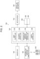
- Fig. 2 is a block diagram illustrating a configuration of the control device 120 included in the mobile object 100.
- the mobile object 100 includes propeller drive motors 150, a motor driver 152, a sensor unit 154, an airframe-side wireless communication unit 156, and the control device 120.
- the control device 120 is constituted by, for example, a microcomputer.
- the control device 120 includes a main control unit 122, a movement control unit 124, an airframe-side wireless communication control unit 126, and a camera control unit 128.
- the main control unit 122 manages all of the respective functions of the movement control unit 124, the airframe-side wireless communication control unit 126, and the camera control unit 128.
- the control device 120 executes a program, thereby being able to function as the main control unit 122, the movement control unit 124, the airframe-side wireless communication control unit 126, and the camera control unit 128.
- the movement control unit 124 controls the driving of the propeller drive motors 150 through the motor driver 152 to control the flight (movement) of the mobile object 100.
- the movement control unit 124 controls, based on a control signal transmitted from the controller 250 and information on a flight state of the mobile object 100, which is output from the sensor unit 154, the driving of each of the propeller drive motors 150 to control the flight of the mobile object 100. For example, upon an instruction from the controller 250 to fly upward, the movement control unit 124 controls the driving of each of the propeller drive motors 150 so that the airframe is raised. Upon an instruction from the controller 250 to fly downward, the movement control unit 124 controls the driving of each of the propeller drive motors 150 so that the airframe is lowered.
- the movement control unit 124 controls the driving of each of the propeller drive motors 150 so that the airframe turns in an instructed direction.
- the movement control unit 124 controls the driving of each of the propeller drive motors 150 so that the airframe flies at a predetermined speed.
- the propeller drive motors 150 cause the propellers (not illustrated) to rotate to apply a propulsive force to the mobile object 100.
- the mobile object 100 includes the plurality of propeller drive motors 150 and propellers and is capable of moving in directions by making the rotational forces of the propellers different. A flight path of the mobile object 100 can be set in advance.
- the sensor unit 154 detects the flight state of the mobile object 100.
- the sensor unit 154 is configured to include various types of sensors such as an IMU (inertial measurement unit) and a GNSS (Global Navigation Satellite System).
- the IMU is configured such that, for example, a gyro sensor, a geomagnetic sensor, an acceleration sensor, a speed sensor, and the like are combined in a plurality of axes.
- the sensor unit 154 outputs information on the flight state of the mobile object 100, which is detected with the various sensors, to the control device 120.
- the airframe-side wireless communication unit 156 wirelessly communicates with the controller 250 and transmits and receives various signals to and from the controller 250 under the control of the control device 120. For example, in the case where the controller 250 is operated, a control signal based on the operation is transmitted from the controller 250 to the mobile object 100. The airframe-side wireless communication unit 156 receives the control signal transmitted from the controller 250 and outputs the control signal to the control device 120.
- the control device 120 includes a CPU (Central Processing Unit), a ROM (Read Only Memory), and a RAM (Random Access Memory), which are not illustrated, and executes a predetermined program to implement various functions.
- the program is stored in the ROM.
- the camera control unit 128 controls the imaging device 200, based on a control signal transmitted from the controller 250. For example, in response to an instruction from the controller 250 to start imaging, the camera control unit 128 causes the imaging device 200 to start imaging. In response to an instruction from the controller 250 to terminate imaging, the camera control unit 128 causes the imaging device 200 to terminate imaging.
- the airframe-side wireless communication control unit 126 controls communication with the controller 250 through the airframe-side wireless communication unit 156.
- a flight plan of the mobile object 100 and imaging conditions of the imaging device 200 can be determined in advance by control software or the like.
- the flight plan includes, for example, a flight path, a speed, and an altitude of the mobile object 100.
- the imaging conditions include causing the imaging device 200 to perform imaging at equal time intervals and to perform imaging at equal distance intervals, and the like. Conditions such as equal time intervals and equal distance intervals are appropriately selected.
- the main control unit 122 controls the movement control unit 124 in accordance with the flight plan.
- the movement control unit 124 controls the driving of the propeller drive motors 150 through the motor driver 152 in accordance with a signal from the main control unit 122.
- the main control unit 122 controls the camera control unit 128 in accordance with the imaging conditions.
- the camera control unit 128 controls the imaging device 200.
- the flight plan and the imaging conditions are combined to determine an overlap rate of imaging ranges along a flight path and a sidelap rate of imaging ranges in adjacent flight paths.
- the mobile object 100 of an embodiment is capable of determining the imaging conditions and the like of the mobile object 100 in accordance with the shape of a target object to be subjected to imaging.
- Fig. 3 is a block diagram illustrating an electric configuration of a controller.
- the controller 250 includes a controller operation unit 250A, a controller display unit 250B, a controller-side wireless communication unit 250C, and a controller microcomputer 250D.
- the controller operation unit 250A is configured to include various operating members for operating the mobile object 100.
- Operating members for operating the mobile object main body 102 including the propulsion unit include, for example, an operating member for instructing the mobile object main body 102 to fly upward or downward, an operating member for instructing the mobile object main body 102 turn, and so on.
- Operating members for operating the imaging device 200 include, for example, an operating member for instructing start of imaging and termination of imaging, and so on.
- the controller display unit 250B is constituted by, for example, an LCD (Liquid Crystal Display).
- the controller display unit 250B displays, for example, information on the flight state of the mobile object 100.
- the controller-side wireless communication unit 250C wirelessly communicates with the mobile object 100 and transmits and receives various signals to and from the mobile object 100 under the control of the controller microcomputer 250D.
- the controller microcomputer 250D is a control unit that integrally controls the overall operation of the controller 250.
- the controller microcomputer 250D includes a CPU, a ROM, and a RAM and executes a predetermined program to implement various functions. For example, when the controller operation unit 250A is operated, a control signal corresponding to the operation is generated. The control signal is transmitted to the mobile object 100 through the controller-side wireless communication unit 250C. Further, the controller 250 acquires flight state information from the mobile object 100 through the controller-side wireless communication unit 250C and displays the flight state information on the controller display unit 250B.
- the program is stored in the ROM.
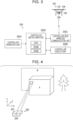
- Fig. 4 is a conceptual diagram of imaging of a target object by an imaging device including an image data acquisition device and a three-dimensional data acquisition device.
- the imaging device 200 includes the image data acquisition device 202 and the three-dimensional data acquisition device 204.
- the target object includes structures A and B having a planar shape, and a structure C having no plane.
- the image data acquisition device 202 acquires two-dimensional image data of the target object.
- the image data acquisition device 202 includes an imaging element such as a CMOS (Complementary Metal Oxide Semiconductor) imaging element (not illustrated).
- CMOS Complementary Metal Oxide Semiconductor
- the imaging element has a plurality of pixels constituted by photoelectric conversion elements arranged two-dimensionally in an x direction (horizontal direction) and a y direction (vertical direction), and color filters (not illustrated) are arranged on an upper surface of the plurality of pixels such that, for example, R (red), G (green), and B (blue) filters are arranged two-dimensionally in a Bayer pattern.
- the image data acquisition device 202 is capable of acquiring two-dimensional color image data.
- the image data acquisition device 202 acquires image data for each angle of view through each imaging operation.
- the imaging range is determined by the angle of view of the image data acquisition device 202.
- the image data acquisition device 202 acquires a plurality of pieces of image data for the target object.
- the angle of view represents an imaging range in which imaging is performed by the image data acquisition device 202.
- the three-dimensional data acquisition device 204 acquires three-dimensional data of the target object.
- the three-dimensional data acquisition device 204 is, for example, a stereo camera.
- the stereo camera is a camera that simultaneously captures image data from a plurality of cameras located at different positions and acquires three-dimensional data up to the target object by using parallax in the image data.
- one of a plurality of cameras can be used as the image data acquisition device 202.
- the image data acquisition device 202 can be provided separately from the three-dimensional data acquisition device 204.
- the three-dimensional data acquisition device 204 is a stereo camera has been described.
- the three-dimensional data can be acquired using a laser scanner or a time-of-flight (ToF) camera.
- TOF time-of-flight
- the laser scanner emits a laser pulse to a target object and measures a distance by the time taken for the laser pulse reflected at the surface of the target object to return. Then, three-dimensional data of the reflection point of the laser pulse is acquired from the measured distance and angle information of the emission direction of the laser pulse. That is, the three-dimensional data includes three-dimensional coordinates.
- the laser scanner is not limited to one based on the time-of-flight method, and can use a phase difference method or a trigonometric method to acquire three-dimensional data.
- the time-of-flight camera is a camera that measures a flight time of light to acquire three-dimensional data.
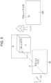
- Fig. 5 is a conceptual diagram describing a correspondence relationship between image data and three-dimensional data.
- Image data ID includes data of a plurality of pixels P that are two-dimensionally arranged.
- the image data ID is data of an angle-of-view range.
- the pixels P have respective values for R, G, and B.
- Fig. 5 illustrates a pixel P at coordinates (Px, Py) in the image data ID, and a point Q having a positional relationship corresponding to the pixel P for the target object.
- the point Q has three-dimensional data (x, y, z), which is position information. That is, the three-dimensional data is three-dimensional coordinates.
- Unit image data UID in which pixels of the image data ID and three-dimensional data TD are associated with each other is acquired.
- Each piece of data PQ of the unit image data UID has the three-dimensional data (x, y, z) of the point Q and information on the values (R, G, B) of the pixel P.
- the imaging device 200 provided in the mobile object 100 acquires a plurality of pieces of unit image data UID for the target object in accordance with the flight plan and the imaging conditions.
- the image data ID and the three-dimensional data TD, which are included in the unit image data UID are preferably acquired simultaneously. The association between the image data ID and the three-dimensional data TD is facilitated.
- the mobile object 100 provided with the imaging device 200 flies around the target object in accordance with the flight plan.
- the image data acquisition device 202 (not illustrated) and the three-dimensional data acquisition device 204 (not illustrated), which are included in the imaging device 200, perform imaging of the target object in accordance with the imaging conditions and acquire a plurality of pieces of unit image data UID.
- the flight plan and the imaging conditions are input from, for example, the controller 250.
- the flight plan includes a range for generating a three-dimensional point group of the target object.
- the imaging conditions include an overlap rate and a sidelap rate for generating a three-dimensional point group by using SfM.
- the imaging device 200 acquires a large amount of image data in accordance with the imaging conditions.
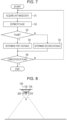
- Fig. 7 is a flowchart describing an image capturing method performed by the imaging device 200 of the mobile object 100.
- the image capturing method includes a unit image data acquisition step (step S 1), a plane estimation step (step S2), a plane determination step (step S3), a first distance determination step (step S4), a second distance determination step (step S5) for determining a second distance shorter than a first distance, and a plan completion determination step (step S6).
- unit image data in which the image data ID and the three-dimensional data TD are associated with each other is acquired for the target object during movement (step S1).
- the mobile object 100 provided with the imaging device 200 flies around the target object in accordance with the flight plan.
- the image data acquisition device 202 (not illustrated) and the three-dimensional data acquisition device 204 (not illustrated), which are included in the imaging device 200, perform imaging of the target object within a range of an angle of view ⁇ in accordance with imaging conditions during movement, and acquire the unit image data UID.
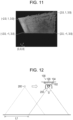
- Fig. 9 is a diagram illustrating an example of the image data ID and the three-dimensional data TD, which are acquired by the imaging device 200.
- the image data acquisition device 202 (not illustrated) acquires the image data ID, which is two-dimensional color image data.
- the three-dimensional data acquisition device 204 (not illustrated) acquires depth data DP up to the target object.
- the unit image data UID in which the image data ID and the three-dimensional data TD are associated with each other is acquired from the image data ID and the depth data DP.
- the depth data DP is indicated in blue in the case that the distance is short, and is indicated in red in the case that the distance is long. In an embodiment, an upper right portion is displayed in a color similar to blue, and a lower left portion is displayed in a color similar to red.
- the unit image data UID is input from the imaging device 200 to the control device 120.
- plane estimation is performed on an imaging target, based on the three-dimensional data TD of the unit image data UID (step S2).
- the plane estimation estimates a plane in an angle-of-view range by the image data acquisition device 202.
- plane estimation is performed by the main control unit 122 in the control device 120.
- x, y, and z are three-dimensional data in directions orthogonal to three axes of the camera coordinate system, and a r , b r , c r , and d r represent coefficients of the plane equation.
- Coefficients a r , b r , c r , and d r of a plane for which the squared distance to each point of the three-dimensional data (x, y, z) is minimum are obtained to determine a plane to be estimated.
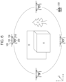
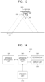
- Fig. 10 is a diagram conceptually illustrating how a plane in the image data ID is estimated from the three-dimensional data TD.
- a plane PL in the three-dimensional data TD of the unit image data UID, a range surrounded by a quadrilateral is estimated as a plane PL.
- the plane PL in the image data ID is estimated.
- the plane determination step it is determined whether the imaging target is a plane (step S3). It is determined whether the most area within the imaging target, that is, within the angle-of-view range, is the plane PL. The determination of whether the imaging target is a plane is performed by, for example, the main control unit 122 in the control device 120. For example, a plane estimated in three-dimensional data is compared with the angle-of-view range. If it is determined in the plane determination step that the imaging target is a plane ("Y" is determined), the process proceeds to a step of determining a first distance.
- a first distance until the next unit image data is acquired is determined based on information on the plane (step S4).
- the coordinates of the three-dimensional data TD of the unit image data UID are added.
- the coordinates are illustrated at the four corners of the estimated plane PL.
- (-2.0, 1, 3.0), (2.0, 1, 3.5), (2.0, -1, 3.5), and (-2.0, -1, 3.0) are illustrated.
- the size (the width W and the height H) of the plane PL is estimated from these four sets of coordinates (see Fig. 10 ).
- a first distance L1 until the next unit image data is acquired can be obtained by formula (2) for movement in the lateral direction and by formula (3) for movement in the longitudinal direction.
- the first distance L1 increases as the overlapping rate decreases.
- the overlapping rate can be set in advance. Different overlapping rates R1 can be set for movement in the lateral direction and movement in the longitudinal direction.
- L 1 Width W of estimated plane ⁇ 100 % ⁇ overlapping rate
- L1 Height H of estimated plane ⁇ 100 % ⁇ overlapping rate R1
- the step of determining the first distance is performed by, for example, the main control unit 122 in the control device 120.
- the first distance L1 is input from the main control unit 122 to the movement control unit 124 and the camera control unit 128, for example.
- the mobile object main body 102 and the imaging device 200 are prepared for the acquisition of the next unit image data.
- a second distance L2 can be obtained in advance as a default value by setting an overlapping rate R2 (an overlap rate and a sidelap rate) on the assumption that a three-dimensional point group based on SfM is created.
- the second distance L2 is a default value.
- Different overlapping rates R2 can be set for movement in the lateral direction and movement in the longitudinal direction.
- L 2 Width W of imaging range ⁇ 100 % ⁇ overlapping rate R2
- L 2 Height H of imaging range ⁇ 100 % ⁇ overlapping rate R2
- the overlapping rate R1 for obtaining the first distance L1 is set smaller than the overlapping rate R2 for obtaining the second distance L2. As a result, the first distance L1 is longer than the second distance L2.
- plan completion determination step it is determined whether the plan (flight plan and imaging conditions) set in advance for the target object is completed (step S6).
- step S4 When the first distance determination step (step S4) is executed, in the unit image data acquisition step (step S1), as illustrated in Fig. 12 , the mobile object 100 moves in parallel by the first distance L1 from the estimated plane while maintaining the distance to the estimated plane.
- the imaging device 200 provided in the mobile object 100 acquires the next unit image data for the target object.
- step S5 When the second distance determination step (step S5) is executed, in the unit image data acquisition step (step S1), as illustrated in Fig. 13 , the mobile object 100 moves in parallel by the second distance L2 from the estimated plane while maintaining the distance to the estimated plane.
- the imaging device 200 provided in the mobile object 100 acquires the next unit image data for the target object.
- the first distance L1 is longer than the second distance L2. That is, upon estimation of a plane, a distance until the next unit image data is acquired is long, and the number of pieces of image data ID to be acquired for the target object can thus be reduced.
- the unit image data acquisition step (step S1), the plane estimation step (step S2), the plane determination step (step S3), the first distance determination step (step S4) or the second distance determination step (step S5), and the plan completion determination step (step S6) are repeatedly executed until it is determined in the plan completion determination step (step S6) that the plan is completed ("Y" is determined). If it is determined in the plan completion determination step (step S6) that the plan is completed ("Y" is determined), the mobile object 100 stops imaging using the imaging device 200 and returns to, for example, a predetermined position.
- the unit image data UID (the image data ID and the three-dimensional data TD) of the target object, which is acquired by the imaging device 200 of the mobile object 100, is input to the image processing apparatus 300.
- the image processing apparatus 300 is constituted by, for example, the operation unit 310, the display unit 320, an apparatus input/output unit 330, an apparatus control unit 340, and a recording unit 350.
- Information is input to and output from the apparatus input/output unit 330 through wireless or wired connection.
- the plurality of pieces of unit image data UID acquired by the mobile object 100 are input through the apparatus input/output unit 330.
- the apparatus control unit 340 acquires the unit image data UID through the apparatus input/output unit 330 and creates a three-dimensional point group. Further, the apparatus control unit 340 controls recording in the recording unit 350, controls display on the display unit 320, and performs control in response to a command input from the operation unit 310.
- the display unit 320 performs display under the control of the apparatus control unit 340. For example, the display unit 320 displays a three-dimensional point group to which damage is mapped.
- the recording unit 350 records various types of information under the control of the apparatus control unit 340. For example, the recording unit 350 records the created three-dimensional point group. The recording unit 350 records various programs for controlling the apparatus control unit 340.
- the plane PL is estimated for a portion of the structure A. Imaging is performed on the plane PL to acquire image data ID. A plurality of pieces of image data ID are acquired by the imaging device 200 by causing the mobile object 100 to move by the first distance L1, as illustrated in Fig. 12 . A plurality of pieces of image data ID of a portion of the structure A other than the plane are acquired by the imaging device 200 by causing the mobile object 100 to move by the second distance L2, as illustrated in Fig. 13 . For a portion of the structure A other than the plane, an image group IG including a plurality of pieces of image data ID necessary for SfM is acquired.
- composite image data CID corresponding to the plane of the structure A can be created.
- the composite image data CID can be created using pattern matching, namely, block matching.
- block matching a block having a predetermined size is set for one of the pieces of image data ID, and the block is scanned across the other pieces of image data ID to calculate correlation values.
- a portion having a highest correlation value is determined as a location that overlaps the block, and adjacent pieces of image data ID are coupled and combined. Since the plane PL is estimated, the pieces of image data ID can accurately be coupled and combined to obtain the composite image data CID.
- the imaging position and the posture of the imaging device 200 and the coordinates of the target object are estimated from the image group IG by using SfM. Further, MVS (Multi-view Stereo) processing is performed to increase the density, and a three-dimensional point group is created.
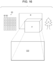
- the image group IG does not include a portion corresponding to the estimated plane PL. Accordingly, the composite image data CID is arranged using point group information that is obtained by SfM and that is adjacent to the plane PL. As a result, as illustrated in Fig. 17 , three-dimensional point groups corresponding to the target object can be created.
- the image group IG and the composite image data CID are subjected to SfM processing to create a three-dimensional point group.
- Known local feature values robust to scaling (different imaging distances), rotation, and the like between the pieces of image data ID include a SIFT (Scale-invariant feature transform) feature value, a SURF (Speed-Upped Robust Feature) feature value, and an AKAZE (Accelerated KAZE) feature value.
- SIFT Scale-invariant feature transform
- SURF Speed-Upped Robust Feature
- AKAZE Accelerated KAZE
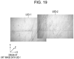
- Fig. 18 illustrates two pieces of unit image data, namely, unit image data UID-1 and unit image data UID-2, which are input to the image processing apparatus 300, in respective camera coordinate systems.
- the camera coordinate systems are coordinate systems of the imaging device 200, with the origin at the center of the lens.
- the unit image data UID-1 and the unit image data UID-2 are obtained at different imaging positions, and the origins of the respective camera coordinate systems are different.
- each point at the coordinates (x, y, z) has values (R, G, B).
- the apparatus control unit 340 extracts feature points, as indicated by arrows, from each of the unit image data UID-1 and the unit image data UID-2. The relationship between the feature points of the unit image data UID-1 and the feature points of the unit image data UID-2 is obtained.
- the unit image data UID-2 can be projected onto the space of the camera coordinate system of the unit image data UID-1.
- the processing described above is performed on the estimated unit image data UID for the plane PL.
- a point group can be collected as a model in the space of one camera coordinate system.
- point group information that is obtained by SfM and that is adjacent to the plane PL, and the point group collected in the processing described above can be used to create the three-dimensional point groups corresponding to the target object illustrated in Fig. 17 in a manner similar to that in the first procedure.
- the unit image data UID is reduced in the image group data, the load of processing using the image data ID is small. Since the plane PL is estimated in the image group data, the relationship of feature points between the pieces of unit image data UID can be easily obtained.
- the first procedure and the second procedure are implemented by the imaging device 200 of the mobile object 100 acquiring a plurality of pieces of image data ID of a target object, extracting a plurality of feature points from the plurality of pieces of image data ID, performing matching of the plurality of feature points, and calculating the position and posture of the imaging device 200 and a three-dimensional point group of the feature points.
- a plane of a target object is estimated to reduce the image data to be acquired. Accordingly, the processing time can be reduced.
- Hardware for implementing an image processing apparatus can be constituted by various processors.
- the various processors include a CPU (Central Processing Unit), which is a general-purpose processor that executes a program to function as various processing units, a programmable logic device (PLD), which is a processor whose circuit configuration can be changed after manufacture, such as an FPGA (Field Programmable Gate Array), a dedicated electric circuit, which is a processor having a circuit configuration designed specifically to execute specific processing, such as an ASIC (Application Specific Integrated Circuit), and so on.
- a single processing unit constituting an image display device may be configured by one of the various processors described above or may be configured by two or more processors of the same type or different types.
- the single processing unit may be configured by a plurality of FPGAs or a combination of a CPU and an FPGA.
- a plurality of processing units may be configured by a single processor.
- Examples of configuring a plurality of processing units by a single processor include, first, a form in which, as typified by a computer such as a client and a server, the single processor is configured by a combination of one or more CPUs and software and the processor functions as a plurality of processing units.
- the examples include, second, a form in which, as typified by a system on chip (SoC) or the like, a processor is used in which the functions of the entire system including the plurality of processing units are implemented by a single IC (Integrated Circuit) chip.
- SoC system on chip
- the various processing units are configured using one or more of the various processors described above as a hardware structure.
- the hardware structure of these various processors can be implemented by, more specifically, an electric circuit (circuitry) made by a combination of circuit elements such as semiconductor elements.
Landscapes
- Engineering & Computer Science (AREA)
- Multimedia (AREA)
- Signal Processing (AREA)
- Studio Devices (AREA)
- Control Of Position, Course, Altitude, Or Attitude Of Moving Bodies (AREA)
- Image Analysis (AREA)
- Length Measuring Devices By Optical Means (AREA)
- Image Processing (AREA)
- Aviation & Aerospace Engineering (AREA)
Claims (7)
- Steuervorrichtung (250), die in einem Hauptkörper eines mobilen Objekts (102) enthalten ist und die konfiguriert ist, um eine Bildgebungsvorrichtung (200) zu steuern, wobei die Bildgebungsvorrichtung eine Abbildung eines Zielobjekts durchführt und eine Bilddatenerfassungsvorrichtung und eine Vorrichtung zur Erfassung dreidimensionaler Daten umfasst, die kalibriert sind, wobeidie Steuervorrichtung konfiguriert ist, um für das Zielobjekt Einheitsbilddaten (UID) zu erfassen, in denen Bilddaten (ID), die für jeden Blickwinkel der Bilddatenerfassungsvorrichtung erfasst werden, und dreidimensionale Daten, die von der Vorrichtung zur Erfassung dreidimensionaler Daten erfasst werden, einander von der Bildgebungsvorrichtung zugeordnet werden,dadurch gekennzeichnet, dass:die Steuervorrichtung ist konfiguriert, auf der Grundlage der dreidimensionalen Daten eine Ebenenabschätzung für ein Abbildungsziel durchzuführen, bestimmt, ob das Abbildungsziel eine Ebene ist, und in dem Fall, in dem bestimmt wird, dass das Abbildungsziel die Ebene ist, basierend auf Informationen über die Ebene, einen ersten Abstand bestimmt, der ein Bewegungsabstand der Bildgebungsvorrichtung ist, bis die nächsten Einheitsbilddaten erfasst werden,wobei in dem Fall, in dem bestimmt wird, dass das Abbildungsziel nicht die Ebene ist, die Steuervorrichtung konfiguriert ist, einen zweiten Abstand, der kürzer als der erste Abstand ist, als einen Abstand zu bestimmen, bis die nächsten Einheitsbilddaten erfasst werden.
- Mobiles Objekt (100) umfassend:einen Hauptkörper des mobilen Objekts (102);eine Bildgebungsvorrichtung (200), die in dem Hauptkörper des mobilen Objekts enthalten ist und die konfiguriert ist, eine Abbildung eines Zielobjekts durchzuführen, wobei die Bildgebungsvorrichtung eine Bilddatenerfassungsvorrichtung (202) und eine Vorrichtung zur Erfassung dreidimensionaler Daten (204), die kalibriert sind, umfasst; unddie Steuereinrichtung (250) gemäß Anspruch 1.
- Mobiles Objekt gemäß Anspruch 2, wobei die Bildgebungsvorrichtung gleichzeitig die Bilddaten und die dreidimensionalen Daten erfasst.
- Mobiles Objekt gemäß Anspruch 2 oder 3, wobei die Vorrichtung zur Erfassung dreidimensionaler Daten eine Stereokamera, einen Laserscanner oder eine Flugzeitkamera umfasst.
- Mobiles Objekt gemäß einem der Ansprüche 2 bis 4, wobei die Bilddaten zweidimensionale Farbbilddaten sind.
- Mobiles Objekt gemäß einem der Ansprüche 2 bis 5, wobei der Hauptkörper des mobilen Objekts umfassend die Bildgebungsvorrichtung und die Steuereinrichtung ein unbemanntes Luftfahrzeug ist.
- Abbildungsverfahren umfassend:einen Schritt des Erfassens, für ein Zielobjekt, von Einheitsbilddaten (UID), in denen Bilddaten (ID) und dreidimensionale Daten einander zugeordnet sind während der Bewegung;dadurch gekennzeichnet, dass es ferner umfasst:einen Schritt des Durchführens einer Ebenenabschätzung an einem Abbildungsziel, basierend auf den dreidimensionalen Daten der Einheitsbilddaten;einen Schritt der Bestimmung, ob das Abbildungsziel eine Ebene ist;einen Schritt des Bestimmens, in dem Fall, in dem bestimmt wird, dass das Abbildungsziel die Ebene ist, basierend auf Informationen über die Ebene, eines ersten Abstands, der ein Bewegungsabstand der Bildgebungsvorrichtung ist, bis die nächsten Einheitsbilddaten erfasst werden; undeinen Schritt des Bestimmens, in dem Fall, in dem bestimmt wird, dass das Abbildungsziel nicht die Ebene ist, einer zweiten Entfernung, die kürzer als die erste Entfernung ist, als eine Entfernung, bis die nächsten Einheitsbilddaten erfasst werden.
Applications Claiming Priority (2)
| Application Number | Priority Date | Filing Date | Title |
|---|---|---|---|
| JP2019221839 | 2019-12-09 | ||
| PCT/JP2020/041641 WO2021117388A1 (ja) | 2019-12-09 | 2020-11-09 | 移動体、制御装置、及び撮像方法 |
Publications (3)
| Publication Number | Publication Date |
|---|---|
| EP4075784A1 EP4075784A1 (de) | 2022-10-19 |
| EP4075784A4 EP4075784A4 (de) | 2023-01-25 |
| EP4075784B1 true EP4075784B1 (de) | 2024-09-04 |
Family
ID=76329752
Family Applications (1)
| Application Number | Title | Priority Date | Filing Date |
|---|---|---|---|
| EP20899530.8A Active EP4075784B1 (de) | 2019-12-09 | 2020-11-09 | Mobile einheit, steuervorrichtung und bildgebungsverfahren |
Country Status (5)
| Country | Link |
|---|---|
| US (1) | US12537926B2 (de) |
| EP (1) | EP4075784B1 (de) |
| JP (2) | JP7444898B2 (de) |
| CN (1) | CN114788256B (de) |
| WO (1) | WO2021117388A1 (de) |
Families Citing this family (1)
| Publication number | Priority date | Publication date | Assignee | Title |
|---|---|---|---|---|
| JP7409330B2 (ja) * | 2021-01-28 | 2024-01-09 | トヨタ自動車株式会社 | 自己位置推定精度検証方法、自己位置推定システム |
Family Cites Families (18)
| Publication number | Priority date | Publication date | Assignee | Title |
|---|---|---|---|---|
| WO2005088244A1 (ja) * | 2004-03-17 | 2005-09-22 | Sony Corporation | 平面検出装置、平面検出方法、及び平面検出装置を搭載したロボット装置 |
| JP2010256252A (ja) * | 2009-04-27 | 2010-11-11 | Topcon Corp | 三次元計測用画像撮影装置及びその方法 |
| JP2013083925A (ja) * | 2011-09-29 | 2013-05-09 | Canon Inc | 撮像装置及びその制御方法 |
| JP5855416B2 (ja) * | 2011-10-25 | 2016-02-09 | Kddi株式会社 | 3次元座標取得装置、カメラ姿勢推定装置、プログラム |
| JP5947634B2 (ja) * | 2012-06-25 | 2016-07-06 | 株式会社トプコン | 航空写真撮像方法及び航空写真撮像システム |
| WO2014147863A1 (ja) * | 2013-03-21 | 2014-09-25 | 日本電気株式会社 | 三次元情報計測・表示装置、三次元情報計測・表示方法及びプログラム |
| JP2015114954A (ja) | 2013-12-13 | 2015-06-22 | 株式会社ジオ技術研究所 | 撮影画像解析方法 |
| JP6590653B2 (ja) * | 2014-11-19 | 2019-10-16 | 首都高技術株式会社 | 点群データ利用システム |
| EP3062066B1 (de) * | 2015-02-26 | 2025-01-15 | Hexagon Technology Center GmbH | Bestimmung von Objektdaten durch vorlagenbasierte UAV-Steuerung |
| US10531073B2 (en) * | 2016-03-17 | 2020-01-07 | Samsung Electronics Co., Ltd. | Method and apparatus for automatic calibration of RGBZ sensors utilizing epipolar geometry and scanning beam projector |
| CN106295141B (zh) * | 2016-08-01 | 2018-12-14 | 清华大学深圳研究生院 | 用于三维模型重建的多条无人机路径确定方法及装置 |
| EP3361235A1 (de) * | 2017-02-10 | 2018-08-15 | VoxelGrid GmbH | Vorrichtung und verfahren zur analyse von objekten |
| US10527711B2 (en) * | 2017-07-10 | 2020-01-07 | Aurora Flight Sciences Corporation | Laser speckle system and method for an aircraft |
| JP2019028560A (ja) * | 2017-07-26 | 2019-02-21 | エスゼット ディージェイアイ テクノロジー カンパニー リミテッドSz Dji Technology Co.,Ltd | モバイルプラットフォーム、画像合成方法、プログラム、及び記録媒体 |
| JP6918672B2 (ja) * | 2017-10-11 | 2021-08-11 | 株式会社日立システムズ | 劣化診断システム |
| JP6586602B1 (ja) * | 2018-06-13 | 2019-10-09 | 株式会社プロドローン | 無人航空機 |
| US10972717B2 (en) * | 2018-06-26 | 2021-04-06 | Solaroid Corporation | Automated feature analysis of a structure |
| ES2968959T3 (es) * | 2018-11-21 | 2024-05-14 | Eagle View Tech Inc | Aeronave no tripulada de navegación que utiliza cabeceo |
-
2020
- 2020-11-09 EP EP20899530.8A patent/EP4075784B1/de active Active
- 2020-11-09 JP JP2021563792A patent/JP7444898B2/ja active Active
- 2020-11-09 CN CN202080084181.4A patent/CN114788256B/zh active Active
- 2020-11-09 WO PCT/JP2020/041641 patent/WO2021117388A1/ja not_active Ceased
-
2022
- 2022-05-18 US US17/747,678 patent/US12537926B2/en active Active
-
2024
- 2024-02-22 JP JP2024025590A patent/JP7765520B2/ja active Active
Also Published As
| Publication number | Publication date |
|---|---|
| EP4075784A1 (de) | 2022-10-19 |
| WO2021117388A1 (ja) | 2021-06-17 |
| JP7765520B2 (ja) | 2025-11-06 |
| CN114788256B (zh) | 2024-10-01 |
| US12537926B2 (en) | 2026-01-27 |
| JPWO2021117388A1 (de) | 2021-06-17 |
| JP7444898B2 (ja) | 2024-03-06 |
| CN114788256A (zh) | 2022-07-22 |
| US20220279155A1 (en) | 2022-09-01 |
| EP4075784A4 (de) | 2023-01-25 |
| JP2024072827A (ja) | 2024-05-28 |
Similar Documents
| Publication | Publication Date | Title |
|---|---|---|
| JP7436657B2 (ja) | 飛行撮影システム及び方法 | |
| CN111448476B (zh) | 在无人飞行器与地面载具之间共享绘图数据的技术 | |
| US10475209B2 (en) | Camera calibration | |
| JP6708790B2 (ja) | 画像生成装置、画像生成システム、画像生成方法、及び画像生成プログラム | |
| CN108628337A (zh) | 路径生成装置、路径控制系统以及路径生成方法 | |
| US10951821B2 (en) | Imaging control device, imaging system, and imaging control method | |
| US20240289978A1 (en) | Movable object, movable object imaging system, and movable object imaging method | |
| JP6821220B2 (ja) | 無人航空機、無人航空機の飛行制御装置、無人航空機の飛行制御方法、及びプログラム | |
| WO2020207411A1 (zh) | 一种图像数据处理方法、装置、图像处理芯片及飞行器 | |
| JP7765520B2 (ja) | 制御装置、撮像システム及び撮像方法 | |
| US12174629B2 (en) | Information processing apparatus, information processing method, program, and information processing system | |
| CN112313599B (zh) | 控制方法、装置和存储介质 | |
| US12146964B2 (en) | Image processing method, image processing apparatus, and image processing program | |
| JP7421572B2 (ja) | 画像処理方法、画像処理装置、画像処理プログラム、及び画像処理システム | |
| JP7184381B2 (ja) | 無人航空機、無人航空機の飛行制御装置、無人航空機の飛行制御方法、及びプログラム | |
| US20240292093A1 (en) | Information processing device, information processing method, and program | |
| EP4429950B1 (de) | Konturabtastung mit einem unbemannten luftfahrzeug | |
| JP2021047738A (ja) | 移動体、飛行経路制御方法及びプログラム | |
| JP2022057660A (ja) | 屋根点検用の無人航空機の制御装置 |
Legal Events
| Date | Code | Title | Description |
|---|---|---|---|
| STAA | Information on the status of an ep patent application or granted ep patent |
Free format text: STATUS: THE INTERNATIONAL PUBLICATION HAS BEEN MADE |
|
| PUAI | Public reference made under article 153(3) epc to a published international application that has entered the european phase |
Free format text: ORIGINAL CODE: 0009012 |
|
| STAA | Information on the status of an ep patent application or granted ep patent |
Free format text: STATUS: REQUEST FOR EXAMINATION WAS MADE |
|
| 17P | Request for examination filed |
Effective date: 20220519 |
|
| AK | Designated contracting states |
Kind code of ref document: A1 Designated state(s): AL AT BE BG CH CY CZ DE DK EE ES FI FR GB GR HR HU IE IS IT LI LT LU LV MC MK MT NL NO PL PT RO RS SE SI SK SM TR |
|
| A4 | Supplementary search report drawn up and despatched |
Effective date: 20221223 |
|
| RIC1 | Information provided on ipc code assigned before grant |
Ipc: H04N 5/222 20060101ALI20221219BHEP Ipc: B64C 39/02 20060101ALI20221219BHEP Ipc: H04N 5/232 20060101AFI20221219BHEP |
|
| DAV | Request for validation of the european patent (deleted) | ||
| DAX | Request for extension of the european patent (deleted) | ||
| REG | Reference to a national code |
Ref country code: DE Ref legal event code: R079 Free format text: PREVIOUS MAIN CLASS: H04N0005232000 Ipc: B64C0039020000 Ref country code: DE Ref legal event code: R079 Ref document number: 602020037333 Country of ref document: DE Free format text: PREVIOUS MAIN CLASS: H04N0005232000 Ipc: B64C0039020000 |
|
| GRAP | Despatch of communication of intention to grant a patent |
Free format text: ORIGINAL CODE: EPIDOSNIGR1 |
|
| STAA | Information on the status of an ep patent application or granted ep patent |
Free format text: STATUS: GRANT OF PATENT IS INTENDED |
|
| RIC1 | Information provided on ipc code assigned before grant |
Ipc: B64U 101/30 20230101ALI20240425BHEP Ipc: H04N 23/60 20230101ALI20240425BHEP Ipc: H04N 5/222 20060101ALI20240425BHEP Ipc: B64C 39/02 20060101AFI20240425BHEP |
|
| INTG | Intention to grant announced |
Effective date: 20240515 |
|
| GRAS | Grant fee paid |
Free format text: ORIGINAL CODE: EPIDOSNIGR3 |
|
| P01 | Opt-out of the competence of the unified patent court (upc) registered |
Free format text: CASE NUMBER: APP_38048/2024 Effective date: 20240626 |
|
| GRAA | (expected) grant |
Free format text: ORIGINAL CODE: 0009210 |
|
| STAA | Information on the status of an ep patent application or granted ep patent |
Free format text: STATUS: THE PATENT HAS BEEN GRANTED |
|
| AK | Designated contracting states |
Kind code of ref document: B1 Designated state(s): AL AT BE BG CH CY CZ DE DK EE ES FI FR GB GR HR HU IE IS IT LI LT LU LV MC MK MT NL NO PL PT RO RS SE SI SK SM TR |
|
| REG | Reference to a national code |
Ref country code: GB Ref legal event code: FG4D |
|
| REG | Reference to a national code |
Ref country code: CH Ref legal event code: EP |
|
| REG | Reference to a national code |
Ref country code: IE Ref legal event code: FG4D |
|
| REG | Reference to a national code |
Ref country code: DE Ref legal event code: R096 Ref document number: 602020037333 Country of ref document: DE |
|
| REG | Reference to a national code |
Ref country code: LT Ref legal event code: MG9D |
|
| REG | Reference to a national code |
Ref country code: NL Ref legal event code: MP Effective date: 20240904 |
|
| PG25 | Lapsed in a contracting state [announced via postgrant information from national office to epo] |
Ref country code: NO Free format text: LAPSE BECAUSE OF FAILURE TO SUBMIT A TRANSLATION OF THE DESCRIPTION OR TO PAY THE FEE WITHIN THE PRESCRIBED TIME-LIMIT Effective date: 20241204 |
|
| PG25 | Lapsed in a contracting state [announced via postgrant information from national office to epo] |
Ref country code: PL Free format text: LAPSE BECAUSE OF FAILURE TO SUBMIT A TRANSLATION OF THE DESCRIPTION OR TO PAY THE FEE WITHIN THE PRESCRIBED TIME-LIMIT Effective date: 20240904 Ref country code: GR Free format text: LAPSE BECAUSE OF FAILURE TO SUBMIT A TRANSLATION OF THE DESCRIPTION OR TO PAY THE FEE WITHIN THE PRESCRIBED TIME-LIMIT Effective date: 20241205 Ref country code: FI Free format text: LAPSE BECAUSE OF FAILURE TO SUBMIT A TRANSLATION OF THE DESCRIPTION OR TO PAY THE FEE WITHIN THE PRESCRIBED TIME-LIMIT Effective date: 20240904 |
|
| PG25 | Lapsed in a contracting state [announced via postgrant information from national office to epo] |
Ref country code: BG Free format text: LAPSE BECAUSE OF FAILURE TO SUBMIT A TRANSLATION OF THE DESCRIPTION OR TO PAY THE FEE WITHIN THE PRESCRIBED TIME-LIMIT Effective date: 20240904 |
|
| PG25 | Lapsed in a contracting state [announced via postgrant information from national office to epo] |
Ref country code: LV Free format text: LAPSE BECAUSE OF FAILURE TO SUBMIT A TRANSLATION OF THE DESCRIPTION OR TO PAY THE FEE WITHIN THE PRESCRIBED TIME-LIMIT Effective date: 20240904 |
|
| PG25 | Lapsed in a contracting state [announced via postgrant information from national office to epo] |
Ref country code: HR Free format text: LAPSE BECAUSE OF FAILURE TO SUBMIT A TRANSLATION OF THE DESCRIPTION OR TO PAY THE FEE WITHIN THE PRESCRIBED TIME-LIMIT Effective date: 20240904 |
|
| PG25 | Lapsed in a contracting state [announced via postgrant information from national office to epo] |
Ref country code: ES Free format text: LAPSE BECAUSE OF FAILURE TO SUBMIT A TRANSLATION OF THE DESCRIPTION OR TO PAY THE FEE WITHIN THE PRESCRIBED TIME-LIMIT Effective date: 20240904 Ref country code: RS Free format text: LAPSE BECAUSE OF FAILURE TO SUBMIT A TRANSLATION OF THE DESCRIPTION OR TO PAY THE FEE WITHIN THE PRESCRIBED TIME-LIMIT Effective date: 20241204 |
|
| PG25 | Lapsed in a contracting state [announced via postgrant information from national office to epo] |
Ref country code: RS Free format text: LAPSE BECAUSE OF FAILURE TO SUBMIT A TRANSLATION OF THE DESCRIPTION OR TO PAY THE FEE WITHIN THE PRESCRIBED TIME-LIMIT Effective date: 20241204 Ref country code: PL Free format text: LAPSE BECAUSE OF FAILURE TO SUBMIT A TRANSLATION OF THE DESCRIPTION OR TO PAY THE FEE WITHIN THE PRESCRIBED TIME-LIMIT Effective date: 20240904 Ref country code: NO Free format text: LAPSE BECAUSE OF FAILURE TO SUBMIT A TRANSLATION OF THE DESCRIPTION OR TO PAY THE FEE WITHIN THE PRESCRIBED TIME-LIMIT Effective date: 20241204 Ref country code: LV Free format text: LAPSE BECAUSE OF FAILURE TO SUBMIT A TRANSLATION OF THE DESCRIPTION OR TO PAY THE FEE WITHIN THE PRESCRIBED TIME-LIMIT Effective date: 20240904 Ref country code: HR Free format text: LAPSE BECAUSE OF FAILURE TO SUBMIT A TRANSLATION OF THE DESCRIPTION OR TO PAY THE FEE WITHIN THE PRESCRIBED TIME-LIMIT Effective date: 20240904 Ref country code: GR Free format text: LAPSE BECAUSE OF FAILURE TO SUBMIT A TRANSLATION OF THE DESCRIPTION OR TO PAY THE FEE WITHIN THE PRESCRIBED TIME-LIMIT Effective date: 20241205 Ref country code: FI Free format text: LAPSE BECAUSE OF FAILURE TO SUBMIT A TRANSLATION OF THE DESCRIPTION OR TO PAY THE FEE WITHIN THE PRESCRIBED TIME-LIMIT Effective date: 20240904 Ref country code: ES Free format text: LAPSE BECAUSE OF FAILURE TO SUBMIT A TRANSLATION OF THE DESCRIPTION OR TO PAY THE FEE WITHIN THE PRESCRIBED TIME-LIMIT Effective date: 20240904 Ref country code: BG Free format text: LAPSE BECAUSE OF FAILURE TO SUBMIT A TRANSLATION OF THE DESCRIPTION OR TO PAY THE FEE WITHIN THE PRESCRIBED TIME-LIMIT Effective date: 20240904 |
|
| REG | Reference to a national code |
Ref country code: AT Ref legal event code: MK05 Ref document number: 1720145 Country of ref document: AT Kind code of ref document: T Effective date: 20240904 |
|
| PG25 | Lapsed in a contracting state [announced via postgrant information from national office to epo] |
Ref country code: NL Free format text: LAPSE BECAUSE OF FAILURE TO SUBMIT A TRANSLATION OF THE DESCRIPTION OR TO PAY THE FEE WITHIN THE PRESCRIBED TIME-LIMIT Effective date: 20240904 |
|
| PG25 | Lapsed in a contracting state [announced via postgrant information from national office to epo] |
Ref country code: IS Free format text: LAPSE BECAUSE OF FAILURE TO SUBMIT A TRANSLATION OF THE DESCRIPTION OR TO PAY THE FEE WITHIN THE PRESCRIBED TIME-LIMIT Effective date: 20250104 Ref country code: PT Free format text: LAPSE BECAUSE OF FAILURE TO SUBMIT A TRANSLATION OF THE DESCRIPTION OR TO PAY THE FEE WITHIN THE PRESCRIBED TIME-LIMIT Effective date: 20250106 |
|
| PG25 | Lapsed in a contracting state [announced via postgrant information from national office to epo] |
Ref country code: SM Free format text: LAPSE BECAUSE OF FAILURE TO SUBMIT A TRANSLATION OF THE DESCRIPTION OR TO PAY THE FEE WITHIN THE PRESCRIBED TIME-LIMIT Effective date: 20240904 Ref country code: RO Free format text: LAPSE BECAUSE OF FAILURE TO SUBMIT A TRANSLATION OF THE DESCRIPTION OR TO PAY THE FEE WITHIN THE PRESCRIBED TIME-LIMIT Effective date: 20240904 |
|
| PG25 | Lapsed in a contracting state [announced via postgrant information from national office to epo] |
Ref country code: EE Free format text: LAPSE BECAUSE OF FAILURE TO SUBMIT A TRANSLATION OF THE DESCRIPTION OR TO PAY THE FEE WITHIN THE PRESCRIBED TIME-LIMIT Effective date: 20240904 Ref country code: AT Free format text: LAPSE BECAUSE OF FAILURE TO SUBMIT A TRANSLATION OF THE DESCRIPTION OR TO PAY THE FEE WITHIN THE PRESCRIBED TIME-LIMIT Effective date: 20240904 |
|
| PG25 | Lapsed in a contracting state [announced via postgrant information from national office to epo] |
Ref country code: CZ Free format text: LAPSE BECAUSE OF FAILURE TO SUBMIT A TRANSLATION OF THE DESCRIPTION OR TO PAY THE FEE WITHIN THE PRESCRIBED TIME-LIMIT Effective date: 20240904 |
|
| PG25 | Lapsed in a contracting state [announced via postgrant information from national office to epo] |
Ref country code: SK Free format text: LAPSE BECAUSE OF FAILURE TO SUBMIT A TRANSLATION OF THE DESCRIPTION OR TO PAY THE FEE WITHIN THE PRESCRIBED TIME-LIMIT Effective date: 20240904 Ref country code: IT Free format text: LAPSE BECAUSE OF FAILURE TO SUBMIT A TRANSLATION OF THE DESCRIPTION OR TO PAY THE FEE WITHIN THE PRESCRIBED TIME-LIMIT Effective date: 20240904 |
|
| REG | Reference to a national code |
Ref country code: DE Ref legal event code: R097 Ref document number: 602020037333 Country of ref document: DE |
|
| REG | Reference to a national code |
Ref country code: CH Ref legal event code: PL |
|
| PG25 | Lapsed in a contracting state [announced via postgrant information from national office to epo] |
Ref country code: MC Free format text: LAPSE BECAUSE OF FAILURE TO SUBMIT A TRANSLATION OF THE DESCRIPTION OR TO PAY THE FEE WITHIN THE PRESCRIBED TIME-LIMIT Effective date: 20240904 |
|
| PG25 | Lapsed in a contracting state [announced via postgrant information from national office to epo] |
Ref country code: DK Free format text: LAPSE BECAUSE OF FAILURE TO SUBMIT A TRANSLATION OF THE DESCRIPTION OR TO PAY THE FEE WITHIN THE PRESCRIBED TIME-LIMIT Effective date: 20240904 |
|
| PLBE | No opposition filed within time limit |
Free format text: ORIGINAL CODE: 0009261 |
|
| STAA | Information on the status of an ep patent application or granted ep patent |
Free format text: STATUS: NO OPPOSITION FILED WITHIN TIME LIMIT |
|
| PG25 | Lapsed in a contracting state [announced via postgrant information from national office to epo] |
Ref country code: LU Free format text: LAPSE BECAUSE OF NON-PAYMENT OF DUE FEES Effective date: 20241109 |
|
| REG | Reference to a national code |
Ref country code: CH Ref legal event code: PL |
|
| PG25 | Lapsed in a contracting state [announced via postgrant information from national office to epo] |
Ref country code: CH Free format text: LAPSE BECAUSE OF NON-PAYMENT OF DUE FEES Effective date: 20241130 |
|
| 26N | No opposition filed |
Effective date: 20250605 |
|
| GBPC | Gb: european patent ceased through non-payment of renewal fee |
Effective date: 20241204 |
|
| REG | Reference to a national code |
Ref country code: BE Ref legal event code: MM Effective date: 20241130 |
|
| PG25 | Lapsed in a contracting state [announced via postgrant information from national office to epo] |
Ref country code: SE Free format text: LAPSE BECAUSE OF FAILURE TO SUBMIT A TRANSLATION OF THE DESCRIPTION OR TO PAY THE FEE WITHIN THE PRESCRIBED TIME-LIMIT Effective date: 20240904 |
|
| PG25 | Lapsed in a contracting state [announced via postgrant information from national office to epo] |
Ref country code: BE Free format text: LAPSE BECAUSE OF NON-PAYMENT OF DUE FEES Effective date: 20241130 Ref country code: GB Free format text: LAPSE BECAUSE OF NON-PAYMENT OF DUE FEES Effective date: 20241204 |
|
| PG25 | Lapsed in a contracting state [announced via postgrant information from national office to epo] |
Ref country code: FR Free format text: LAPSE BECAUSE OF NON-PAYMENT OF DUE FEES Effective date: 20241130 |
|
| PG25 | Lapsed in a contracting state [announced via postgrant information from national office to epo] |
Ref country code: IE Free format text: LAPSE BECAUSE OF NON-PAYMENT OF DUE FEES Effective date: 20241109 |
|
| PGFP | Annual fee paid to national office [announced via postgrant information from national office to epo] |
Ref country code: DE Payment date: 20250930 Year of fee payment: 6 |
|
| PG25 | Lapsed in a contracting state [announced via postgrant information from national office to epo] |
Ref country code: HU Free format text: LAPSE BECAUSE OF FAILURE TO SUBMIT A TRANSLATION OF THE DESCRIPTION OR TO PAY THE FEE WITHIN THE PRESCRIBED TIME-LIMIT; INVALID AB INITIO Effective date: 20201109 |