EP4075568A1 - Electricity storage device and electricity storage method - Google Patents
Electricity storage device and electricity storage method Download PDFInfo
- Publication number
- EP4075568A1 EP4075568A1 EP20898139.9A EP20898139A EP4075568A1 EP 4075568 A1 EP4075568 A1 EP 4075568A1 EP 20898139 A EP20898139 A EP 20898139A EP 4075568 A1 EP4075568 A1 EP 4075568A1
- Authority
- EP
- European Patent Office
- Prior art keywords
- cell batteries
- voltage
- electricity storage
- cell
- electricity
- Prior art date
- Legal status (The legal status is an assumption and is not a legal conclusion. Google has not performed a legal analysis and makes no representation as to the accuracy of the status listed.)
- Pending
Links
Images




Classifications
-
- H—ELECTRICITY
- H02—GENERATION; CONVERSION OR DISTRIBUTION OF ELECTRIC POWER
- H02J—ELECTRIC POWER NETWORKS; CIRCUIT ARRANGEMENTS OR SYSTEMS FOR SUPPLYING OR DISTRIBUTING ELECTRIC POWER; SYSTEMS FOR STORING ELECTRIC ENERGY
- H02J7/00—Circuit arrangements for charging or discharging batteries or for supplying loads from batteries
- H02J7/50—Circuit arrangements for charging or discharging batteries or for supplying loads from batteries acting upon multiple batteries simultaneously or sequentially
- H02J7/52—Circuit arrangements for charging or discharging batteries or for supplying loads from batteries acting upon multiple batteries simultaneously or sequentially for charge balancing, e.g. equalisation of charge between batteries
- H02J7/54—Passive balancing, e.g. using resistors or parallel MOSFETs
-
- H—ELECTRICITY
- H01—ELECTRIC ELEMENTS
- H01M—PROCESSES OR MEANS, e.g. BATTERIES, FOR THE DIRECT CONVERSION OF CHEMICAL ENERGY INTO ELECTRICAL ENERGY
- H01M10/00—Secondary cells; Manufacture thereof
- H01M10/42—Methods or arrangements for servicing or maintenance of secondary cells or secondary half-cells
- H01M10/425—Structural combination with electronic components, e.g. electronic circuits integrated to the outside of the casing
- H01M10/4257—Smart batteries, e.g. electronic circuits inside the housing of the cells or batteries
-
- H—ELECTRICITY
- H01—ELECTRIC ELEMENTS
- H01M—PROCESSES OR MEANS, e.g. BATTERIES, FOR THE DIRECT CONVERSION OF CHEMICAL ENERGY INTO ELECTRICAL ENERGY
- H01M10/00—Secondary cells; Manufacture thereof
- H01M10/42—Methods or arrangements for servicing or maintenance of secondary cells or secondary half-cells
- H01M10/44—Methods for charging or discharging
- H01M10/441—Methods for charging or discharging for several batteries or cells simultaneously or sequentially
-
- H—ELECTRICITY
- H01—ELECTRIC ELEMENTS
- H01M—PROCESSES OR MEANS, e.g. BATTERIES, FOR THE DIRECT CONVERSION OF CHEMICAL ENERGY INTO ELECTRICAL ENERGY
- H01M10/00—Secondary cells; Manufacture thereof
- H01M10/42—Methods or arrangements for servicing or maintenance of secondary cells or secondary half-cells
- H01M10/48—Accumulators combined with arrangements for measuring, testing or indicating the condition of cells, e.g. the level or density of the electrolyte
- H01M10/482—Accumulators combined with arrangements for measuring, testing or indicating the condition of cells, e.g. the level or density of the electrolyte for several batteries or cells simultaneously or sequentially
-
- H—ELECTRICITY
- H02—GENERATION; CONVERSION OR DISTRIBUTION OF ELECTRIC POWER
- H02J—ELECTRIC POWER NETWORKS; CIRCUIT ARRANGEMENTS OR SYSTEMS FOR SUPPLYING OR DISTRIBUTING ELECTRIC POWER; SYSTEMS FOR STORING ELECTRIC ENERGY
- H02J7/00—Circuit arrangements for charging or discharging batteries or for supplying loads from batteries
- H02J7/50—Circuit arrangements for charging or discharging batteries or for supplying loads from batteries acting upon multiple batteries simultaneously or sequentially
-
- H—ELECTRICITY
- H02—GENERATION; CONVERSION OR DISTRIBUTION OF ELECTRIC POWER
- H02J—ELECTRIC POWER NETWORKS; CIRCUIT ARRANGEMENTS OR SYSTEMS FOR SUPPLYING OR DISTRIBUTING ELECTRIC POWER; SYSTEMS FOR STORING ELECTRIC ENERGY
- H02J7/00—Circuit arrangements for charging or discharging batteries or for supplying loads from batteries
- H02J7/90—Regulation of charging or discharging current or voltage
- H02J7/94—Regulation of charging or discharging current or voltage in response to battery current
-
- H—ELECTRICITY
- H02—GENERATION; CONVERSION OR DISTRIBUTION OF ELECTRIC POWER
- H02J—ELECTRIC POWER NETWORKS; CIRCUIT ARRANGEMENTS OR SYSTEMS FOR SUPPLYING OR DISTRIBUTING ELECTRIC POWER; SYSTEMS FOR STORING ELECTRIC ENERGY
- H02J7/00—Circuit arrangements for charging or discharging batteries or for supplying loads from batteries
- H02J7/90—Regulation of charging or discharging current or voltage
- H02J7/96—Regulation of charging or discharging current or voltage in response to battery voltage
-
- B—PERFORMING OPERATIONS; TRANSPORTING
- B60—VEHICLES IN GENERAL
- B60L—PROPULSION OF ELECTRICALLY-PROPELLED VEHICLES; SUPPLYING ELECTRIC POWER FOR AUXILIARY EQUIPMENT OF ELECTRICALLY-PROPELLED VEHICLES; ELECTRODYNAMIC BRAKE SYSTEMS FOR VEHICLES IN GENERAL; MAGNETIC SUSPENSION OR LEVITATION FOR VEHICLES; MONITORING OPERATING VARIABLES OF ELECTRICALLY-PROPELLED VEHICLES; ELECTRIC SAFETY DEVICES FOR ELECTRICALLY-PROPELLED VEHICLES
- B60L58/00—Methods or circuit arrangements for monitoring or controlling batteries or fuel cells, specially adapted for electric vehicles
- B60L58/10—Methods or circuit arrangements for monitoring or controlling batteries or fuel cells, specially adapted for electric vehicles for monitoring or controlling batteries
- B60L58/18—Methods or circuit arrangements for monitoring or controlling batteries or fuel cells, specially adapted for electric vehicles for monitoring or controlling batteries of two or more battery modules
- B60L58/22—Balancing the charge of battery modules
-
- G—PHYSICS
- G01—MEASURING; TESTING
- G01R—MEASURING ELECTRIC VARIABLES; MEASURING MAGNETIC VARIABLES
- G01R31/00—Arrangements for testing electric properties; Arrangements for locating electric faults; Arrangements for electrical testing characterised by what is being tested not provided for elsewhere
- G01R31/36—Arrangements for testing, measuring or monitoring the electrical condition of accumulators or electric batteries, e.g. capacity or state of charge [SoC]
- G01R31/396—Acquisition or processing of data for testing or for monitoring individual cells or groups of cells within a battery
-
- H—ELECTRICITY
- H01—ELECTRIC ELEMENTS
- H01M—PROCESSES OR MEANS, e.g. BATTERIES, FOR THE DIRECT CONVERSION OF CHEMICAL ENERGY INTO ELECTRICAL ENERGY
- H01M10/00—Secondary cells; Manufacture thereof
- H01M10/42—Methods or arrangements for servicing or maintenance of secondary cells or secondary half-cells
- H01M10/425—Structural combination with electronic components, e.g. electronic circuits integrated to the outside of the casing
-
- H—ELECTRICITY
- H01—ELECTRIC ELEMENTS
- H01M—PROCESSES OR MEANS, e.g. BATTERIES, FOR THE DIRECT CONVERSION OF CHEMICAL ENERGY INTO ELECTRICAL ENERGY
- H01M10/00—Secondary cells; Manufacture thereof
- H01M10/42—Methods or arrangements for servicing or maintenance of secondary cells or secondary half-cells
- H01M10/425—Structural combination with electronic components, e.g. electronic circuits integrated to the outside of the casing
- H01M2010/4271—Battery management systems including electronic circuits, e.g. control of current or voltage to keep battery in healthy state, cell balancing
-
- H—ELECTRICITY
- H02—GENERATION; CONVERSION OR DISTRIBUTION OF ELECTRIC POWER
- H02J—ELECTRIC POWER NETWORKS; CIRCUIT ARRANGEMENTS OR SYSTEMS FOR SUPPLYING OR DISTRIBUTING ELECTRIC POWER; SYSTEMS FOR STORING ELECTRIC ENERGY
- H02J7/00—Circuit arrangements for charging or discharging batteries or for supplying loads from batteries
- H02J7/50—Circuit arrangements for charging or discharging batteries or for supplying loads from batteries acting upon multiple batteries simultaneously or sequentially
- H02J7/52—Circuit arrangements for charging or discharging batteries or for supplying loads from batteries acting upon multiple batteries simultaneously or sequentially for charge balancing, e.g. equalisation of charge between batteries
-
- Y—GENERAL TAGGING OF NEW TECHNOLOGICAL DEVELOPMENTS; GENERAL TAGGING OF CROSS-SECTIONAL TECHNOLOGIES SPANNING OVER SEVERAL SECTIONS OF THE IPC; TECHNICAL SUBJECTS COVERED BY FORMER USPC CROSS-REFERENCE ART COLLECTIONS [XRACs] AND DIGESTS
- Y02—TECHNOLOGIES OR APPLICATIONS FOR MITIGATION OR ADAPTATION AGAINST CLIMATE CHANGE
- Y02E—REDUCTION OF GREENHOUSE GAS [GHG] EMISSIONS, RELATED TO ENERGY GENERATION, TRANSMISSION OR DISTRIBUTION
- Y02E60/00—Enabling technologies; Technologies with a potential or indirect contribution to GHG emissions mitigation
- Y02E60/10—Energy storage using batteries
Definitions
- the present disclosure relates to an electricity storage device and an electricity storage method.
- a management module that monitors the voltages of a plurality of serially connected cell batteries.
- the management module detects imbalances in the cell batteries such as the batteries having different remaining capacities. Furthermore, the management module, for example, balances the capacities of the plurality of cell batteries by causing electricity to be discharged from at least one of the cell batteries.
- a reference voltage value is set and the capacities of a plurality of cell batteries are balanced in accordance with the differences between the times taken for the voltages of the respective cells to reach the reference voltage value.
- An electricity storage device includes: a plurality of cell batteries serially connected; and a management module including a balance circuit that can selectively cause electricity to be discharged from each of the plurality of cell batteries, and a controller.
- the controller includes a current-voltage acquiring unit that acquires a charging current and respective voltages of the plurality of cell batteries, and a balance control unit that, if a determination condition and an execution condition are satisfied, determines a lowest-voltage cell battery having a lowest voltage among the plurality of cell batteries and controls the balance circuit such that electricity is discharged from the plurality of cell batteries other than the lowest-voltage cell battery for time periods in accordance with differences between the lowest voltage and the respective voltages of the cell batteries when the determination condition and the execution condition are satisfied.
- An electricity storage method includes: acquiring a charging current and respective voltages of a plurality of cell batteries; determining a lowest-voltage cell battery having a lowest voltage among the plurality of cell batteries if a determination condition and an execution condition are satisfied; and causing electricity to be discharged from the plurality of cell batteries other than the lowest-voltage cell battery for time periods in accordance with differences between the lowest voltage and the respective voltages of the cell batteries when the determination condition and the execution condition are satisfied.
- Fig. 1 is a diagram illustrating an example configuration of an electricity storage system 100 including an electricity storage device 1 according to an embodiment of the present disclosure.
- the electricity storage system 100 is connected to a power system 60 and supplies power to a load 70 connected to the power system 60.
- the load 70 may be included in an electrical appliance that consumes power such as a light, an air conditioner, or an information processing device.
- the electricity storage system 100 stores power supplied from the power system 60 in the electricity storage device 1.
- the electricity storage system 100 includes a power control device 10 and the electricity storage device 1.
- the number of electricity storage devices 1 included in the electricity storage system 100 is not limited. In the example in Fig. 1 , a plurality of electricity storage devices 1 are included in the electricity storage system 100, but alternatively a single electricity storage device 1 may be included in the electricity storage system 100.
- the plurality of electricity storage devices 1 are connected in parallel with the power control device 10.
- the electricity storage device 1 is connected to the power system 60 and the load 70 via the power control device 10.
- the configurations of the plurality of electricity storage devices 1 are identical. Therefore, Fig. 1 illustrates an example configuration of a single electricity storage device 1.
- the power control device 10 may also be called a power conditioning system (PCS). Furthermore, the power control device 10 may be referred to as a power conditioner.
- the power control device 10 controls operations of the electricity storage system 100 in an integrated manner in order to realize a variety of functions.
- the power control device 10, for example, controls input and output between the electricity storage devices 1, the power system 60, and the load 70. In particular, the power control device 10 controls charging of power to the electricity storage devices 1.
- the power control device 10 converts DC power supplied from the electricity storage devices 1 into AC power and outputs the AC power to the power system 60 or the load 70.
- the electricity storage devices 1 store power supplied from the power system 60.
- the electricity storage devices 1 supply power stored in the load 70.
- the electricity storage devices 1 may supply to the power system 60 power that can be sold.
- “discharging" of a cell battery C N of the electricity storage devices 1 refers to consuming of stored power in a balance circuit 20 during execution of balance control, which is described later, rather than supplying of power to the load 70.
- Each electricity storage device 1 includes a management module 2 and an electricity storage module 3.
- the management module 2 includes the balance circuit 20, a storage 21, a controller 22, and a counter 23.
- the controller 22 includes a current-voltage acquiring unit 220 and a balance control unit 221.
- Fig. 1 illustrates an example.
- the electricity storage device 1 does not have to include all the constituent elements illustrated in Fig. 1 .
- the electricity storage device 1 may include constituent elements other than those illustrated in Fig. 1 .
- the electricity storage module 3 includes a plurality of cell batteries C 1 to C M serially connected.
- M is an integer greater than or equal to 2.
- the plurality of cell batteries C 1 to C M are secondary batteries.
- the cell battery C N-1 , the cell battery C N , and the cell battery C N+1 make up some of the plurality of cell batteries C 1 to C M .
- N is 1, the cell battery C N-1 is omitted.
- the cell battery C N+1 is omitted.
- the cell battery may be referred to as a cell battery C N .
- the management module 2 may also be called a battery management system (BMS).
- BMS battery management system
- the management module 2 manages the electricity storage module 3.
- the management module 2 monitors the voltages and currents in units of a cell battery C N and suppresses variations in the capacities of the plurality of cell batteries C 1 to C M .
- the balance circuit 20 is a circuit that can selectively cause electricity to be discharged from each of the plurality of cell batteries C 1 to C M .
- the balance circuit 20 causes electricity to be discharged from a specified cell battery in accordance with control performed by the balance control unit 221. In this embodiment, the balance circuit 20 can cause electricity to be discharged from one cell battery at a time.
- the specific configuration of the balance circuit 20 will be described later.
- the storage 21 stores programs and data as a storage unit.
- the storage 21 temporarily stores results of processing performed by the controller 22.
- the storage 21 may include any suitable storage device such as a semiconductor storage device, an optical storage device, and a magnetic storage device.
- a semiconductor storage device may include, for example, a semiconductor memory.
- the storage 21 may include a plurality of types of storage devices.
- the storage 21 may include a combination of a portable storage medium such as a memory card and a device that reads a storage medium.
- Programs stored in the storage 21 include programs that make the controller 22 function as the current-voltage acquiring unit 220 and the balance control unit 221.
- the controller 22 is a processor such as a central processing unit (CPU), for example.
- the controller 22 may be an integrated circuit such as a System-on-a-Chip (SoC) into which other constituent elements are integrated.
- SoC System-on-a-Chip
- the controller 22 may be formed by combining a plurality of integrated circuits.
- the controller 22 controls operations of the electricity storage device 1 in an integrated manner and realizes a plurality of functions. Specifically, the controller 22 refers to data stored in the storage 21 as necessary.
- the controller 22 realizes various functions by executing commands included in the programs stored in the storage 21. In this embodiment, the controller 22 realizes the functions of the current-voltage acquiring unit 220 and the balance control unit 221 by executing commands of programs read out from the storage 21.
- the current-voltage acquiring unit 220 acquires a charging current I c (refer to Fig. 2 ) and the respective voltages of the plurality of cell batteries C 1 to C M .
- the current-voltage acquiring unit 220 continuously acquires the charging current I c and the respective voltages of the plurality of cell batteries C 1 to C M while the electricity storage device 1 is operating.
- the current-voltage acquiring unit 220 outputs the obtained charging current I c and voltages to the balance control unit 221.
- the balance control unit 221 causes electricity to be discharged from an intended cell battery C N for a set discharge time period in order to suppress variations between the capacities of the plurality of cell batteries C 1 to C M . Specifically, the balance control unit 221 determines a lowest-voltage cell battery having a lowest voltage V min (refer to Fig. 5 ) among the plurality of cell batteries C 1 to C M if a determination condition and an execution condition are satisfied. The balance control unit 221 controls the balance circuit 20 such that electricity is discharged from the plurality of cell batteries C 1 to C M other than the lowest-voltage cell battery for time periods in accordance with the differences between the lowest voltage V min and the voltages of the cell batteries when the determination condition and the execution condition are satisfied.
- the determination condition, the execution condition, and control of the balance circuit 20 will be described in detail later.
- the counter 23 functions as a timer that measures a unit of time.
- the counter 23 may be, for example, an up counter, a down counter, or an up-down counter.
- the unit of time may be, for example, 10 minutes, 5 minutes, or 1 hour.
- the type of counter 23 and the unit of time are not limited.
- Fig. 2 is a diagram illustrating an example configuration of the balance circuit 20.
- the balance circuit 20 includes discharge circuits that each include a switch and a resistor.
- the balance circuit 20 is provided with a discharge circuit for each of the plurality of cell batteries C 1 to C M .
- the switches in Fig. 2 are metal-oxide-semiconductor field-effect transistors (MOSFETs) but do not have to be MOSFETs.
- MOSFETs metal-oxide-semiconductor field-effect transistors
- the gate of the MOSFET of each discharge circuit is controlled by the controller 22 and the MOSFET is switched between an on state and an off state.
- the gate of the MOSFET of the discharge circuit of the cell battery C N is connected to an SW(N) terminal of the controller 22.
- the MOSFET of the discharge circuit of the cell battery C N is switched to an on state if a high-level signal is output from the SW(N) terminal of the controller 22. Furthermore, the MOSFET of the discharge circuit of the cell battery C N is switched to an off state if a low-level signal is output from the SW(N) terminal of the controller 22.
- the drain of the MOSFET of the discharge circuit of the cell battery C N is electrically connected to a wiring line L N .
- the drain of the MOSFET of the discharge circuit of the cell battery C N is also connected to the source of the MOSFET of the discharge circuit of the cell battery C N+1 via a resistor.
- the source of the MOSFET of the discharge circuit of the cell battery C N is electrically connected to a wiring line L N-1 via a resistor.
- a leakage current I d flows between the drain and source when the MOSFET of the discharge circuit of the cell battery C N is switched to the on state. In other words, electricity is discharged from the cell battery C N and a state of charge (SOC) and the voltage of the cell battery C N can be lowered when the MOSFET of the discharge circuit of the cell battery C N is switched to the on state.
- SOC state of charge
- the wiring lines connected to the terminals of the plurality of cell batteries C 1 to C M are electrically connected to the controller 22 of the management module 2.
- the current-voltage acquiring unit 220 of the controller 22 can acquire the respective voltages of the plurality of cell batteries C 1 to C M by obtaining voltage differences between adjacent wiring lines.
- one end of the wiring line L N is connected to a Vs(N) terminal of the controller 22 via the balance circuit 20.
- the other end of the wiring line L N is connected to a negative terminal of the cell battery C N+1 and a positive terminal of the cell battery C N .
- one end of the wiring line L N-1 is connected to a Vs(N-1) terminal of the controller 22 via the balance circuit 20.
- the other end of the wiring line L N-1 is connected to a negative terminal of the cell battery C N and a positive terminal of the cell battery C N-1 .
- the current-voltage acquiring unit 220 can acquire the voltage of the cell battery C N by obtaining the difference between the voltage of the wiring line L N and the voltage of the wiring line L N-1 .
- the electricity storage device 1 charges the electricity storage module 3 with power in accordance with control performed by the power control device 10.
- Fig. 2 illustrates the electricity storage module 3 during charging and the charging current I c flows through the plurality of cell batteries C 1 to C M .
- the current-voltage acquiring unit 220 acquires the charging current I c by accepting a signal from a current sensor provided in series with the plurality of cell batteries C 1 to C M , for example.
- Figs. 3 and 4 are diagrams for explaining an imbalance in the capacities of the plurality of cell batteries C 1 to C M .
- three cell batteries namely, a cell battery C A , a cell battery C B , and a cell battery C C among the plurality of cell batteries C 1 to C M are used in the explanation.
- Fig. 3 illustrates an example of the initial states of the SOCs of the cell battery C A , the cell battery C B , and the cell battery Cc.
- the SOC levels of the cell battery C A , the cell battery C B , and the cell battery C C are uniform.
- the SOCs of the cell battery C A and the cell battery C C are also p%.
- all the capacities of the cell battery C A , the cell battery C B , and the cell battery C C can be used.
- the state illustrated in Fig. 3 is a state in which the capacities are balanced.
- Fig. 4 illustrates an example of the states of the cell battery C A , the cell battery C B , and the cell battery C C after charging and discharging have been repeated in the electricity storage module 3 from the state in Fig. 3 .
- the level of the SOC of the cell battery C C is shifted from that of the cell battery C A and that of the cell battery C B .
- the state illustrated in Fig. 4 is a state in which the capacities are imbalanced.
- the shift in the charged state represented by the cell battery C C in Fig. 4 is called an SOC shift.
- balance control is performed by causing electricity to be discharged from the cell battery C A and the cell battery C B , which reach an SOC of 100% earlier during charging.
- balance control is performed by discharging electricity from the cell batteries other than the cell battery C C having the lowest voltage V min .
- the power consumption of the cell battery C A and the cell battery C B is larger than that of the cell battery Cc, and therefore the level at which the SOCs of the cell battery C A and the cell battery C B is 0% and the level at which the SOC of the cell battery C C is 0% come closer together. Capacity variations are gradually reduced as charging-discharging cycles are repeatedly performed while executing the balance control.
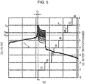
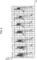
- Figs. 5 and 6 are diagrams illustrating an example of balance control and changes that occur in the voltages of the plurality of cell batteries C 1 to C M .
- the horizontal axis in Figs. 5 and 6 represents time.
- the vertical axis represents the voltages of the cell batteries and the identification numbers of the cell batteries.
- Curves P represent changes in the voltages of the plurality of cell batteries C 1 to C M .
- a solid line Q shaped like a staircase indicates, with identification numbers, cell batteries from which electricity is being discharged.
- M which indicates the total number of cell batteries, is 16.
- the subscript numbers of the plurality of cell batteries C 1 to C M are used as their identification numbers.
- the electricity storage device 1 charges the electricity storage module 3 with power until a time to in accordance with control performed by the power control device 10.
- the time t 0 is the time at which at least one of the voltages of the plurality of charging cell batteries C 1 to C M has reached a set voltage upper limit Vm.
- the voltage upper limit Vm is 3.6 [V], for example.
- the determination condition is satisfied in a period T j before the time to.
- the balance control unit 221 determines a lowest-voltage cell battery having a lowest voltage V min among the plurality of cell batteries C 1 to C M if the determination condition and the execution condition are satisfied.
- the lowest-voltage cell battery is the cell battery C 16 having an identification number of 16.
- the determination condition is a condition for determining whether or not data necessary for determining whether to perform balancing control is present.
- the electricity storage device 1 determines an imbalance in the capacities of the cell batteries during the period T j in which the determination condition is satisfied.
- the determination condition includes at least one of the voltages of the plurality of cell batteries C 1 to C M being greater than or equal to a second voltage threshold V th2 (condition A), the charging current I c being greater than a first current threshold (condition B), and the charging current I c being less than or equal to a second current threshold (condition C).
- the second voltage threshold V th2 is a threshold for detecting that charging is nearing completion and is defined on the basis of the voltage upper limit Vm.
- the second voltage threshold V th2 is 3.5 [V], for example.
- the first current threshold is a threshold for detecting that the electricity storage module 3 is being charged and that the charging current I c is flowing.
- the first current threshold is 0.5 [A], for example.
- the second current threshold is a threshold for detecting that charging of the electricity storage module 3 is being executed normally.
- the second current threshold is 1.0 [A], for example.
- the determination condition is satisfied.
- part (for example, condition C) of the determination condition does not have to be included.
- the determination condition may include further additional conditions.
- the execution condition is a condition for determining whether an imbalance has occurred in the capacities of the cell batteries, i.e., whether or not to execute balance control.
- the electricity storage device 1 executes balance control if the execution condition is satisfied.
- the execution condition includes the magnitude of a difference between the voltages of the plurality of cell batteries C 1 to C M being greater than or equal to a third voltage threshold when the above determination condition is satisfied.
- the third voltage threshold is determined on the basis of voltage variations caused by unacceptable SOC shifts in the specifications of the electricity storage device 1.
- the third voltage threshold is 0.1 [V], for example.
- the balance control unit 221 sets the discharge time periods of the plurality of cell batteries C 1 to C M except for the lowest-voltage cell battery.
- a discharge time period is the time period for which discharging is performed on an intended cell battery from which electricity is discharged by the balance circuit 20, specifically, the time period for which the balance control unit 221 turns on the switch of the discharge circuit to which the intended cell battery is connected.
- the discharge time periods are set in accordance with the differences between the voltages of the cell batteries C N for which the determination condition and the execution condition are satisfied and the lowest voltage V min of the cell battery C 16 .
- the differences between the voltages of the cell batteries C N and the lowest voltage V min in this case are referred to as voltage differences ⁇ V.
- the discharge time periods are set so as to be longer when the voltage differences ⁇ V are larger.
- the balance control unit 221 may set the discharge time periods on the basis of the unit time measured by the counter 23. In this case, the balance control unit 221 can effectively manage the discharge time periods of the plurality of cell batteries C 1 to C M using a single counter 23. In the case where discharging is stopped and restarted as described later, the balance control unit 221 can properly manage the remaining discharge time periods of the stopped cell batteries by matching stopping and restarting of operation of the counter 23 with stopping and restarting of discharging of the cell batteries. In the example in Figs. 5 and 6 , the unit time is 10 minutes. The balance control unit 221 sets the discharge time period to 30 minutes if the voltage difference ⁇ V is greater than 150 [mV].
- the balance control unit 221 sets the discharge time period to 20 minutes if the voltage difference ⁇ V is greater than 100 [mV] and less than or equal to 150 [mV].
- the balance control unit 221 sets the discharge time period to 10 minutes if the voltage difference ⁇ V is greater than 50 [mV] and less than or equal to 100 [mV].
- the balance control unit 221 sets the discharge time period to 0 minutes if the voltage difference ⁇ V is greater than or equal to 0 [mV] and less than or equal to 50 [mV].
- the discharge time periods of the cell batteries C 1 , C 2 , and C 8 are set to 30 minutes.
- the discharge time periods of the cell batteries C 4 to C 7 and C 9 to C 12 are set to 20 minutes.
- the discharge time periods of the cell batteries C 3 and C 13 to C 15 are set to 10 minutes.
- the balance control unit 221 controls the balance circuit 20 in accordance with the intended cell batteries from which electricity is discharged and the discharge time periods set as described above. In other words, the balance control unit 221 executes balance control.
- the balance control unit 221 controls the balance circuit 20 such that electricity is discharged from the plurality of cell batteries other than the lowest-voltage cell battery in a predetermined order.
- the balance control unit 221 executes discharging of the cell batteries in the order of the identification numbers of the cell batteries. As illustrated in Fig. 5 , discharging of the cell battery C 1 is executed for 30 minutes, and then discharging of the cell battery C 2 is executed for 30 minutes, and after that, discharging is executed in the order of the identification numbers.
- the predetermined order is not limited to the order of the identification numbers of the cell batteries. For example, as another embodiment, discharging of the cell batteries may be performed in descending order of discharge time period.
- the balance control unit 221 controls the balance circuit 20 so as to stop discharging of the plurality of cell batteries C 1 to C M if at least one voltage out of the voltages of the plurality of cell batteries C 1 to C M is smaller than a first voltage threshold V th1 .
- the first voltage threshold V th1 is a threshold for detecting a situation in which excessive discharging may occur.
- the first voltage threshold V th1 is 3.0 [V], for example.
- balance control is stopped because at least one of the voltages of the plurality of cell batteries C 1 to C M has fallen below the first voltage threshold V th1 at a time ti.
- the electricity storage device 1 can avoid a situation in which excessive discharging occurs during the balance control.
- the balance control unit 221 may restart balance control that has been stopped once charging of the electricity storage module 3 has restarted.
- the balance control unit 221 controls the balance circuit 20 so as to cause the plurality of cell batteries C 1 to C M that have stopped discharging to restart discharging if all of the voltages of the plurality of cell batteries C 1 to C M are greater than or equal to the first voltage threshold V th1 and the charging current I c is greater than or equal to the first current threshold.
- the first current threshold is a threshold for detecting that the electricity storage module 3 is being charged and that the charging current I c is flowing.
- the first current threshold is 0.5 [A], for example. As illustrated in Fig.
- Fig. 7 is a flowchart illustrating an example of an electricity storage method executed by the electricity storage device 1.
- the electricity storage device 1 executes integrated control of the electricity storage device 1 including the above-described balance control in accordance with the flowchart illustrated in Fig. 7 .
- the controller 22 of the electricity storage device 1 acquires the charging current I c and the respective voltages of the plurality of cell batteries C 1 to C M (step S1).
- the charging current I c and the voltages are continuously acquired while the electricity storage device 1 is operating.
- the controller 22 of the electricity storage device 1 advances to the processing of step S3 in the case where balance control is stopped (Yes in step S2). As illustrated in Fig. 6 , stopping of balance control occurs when at least one of the voltages of the plurality of cell batteries C 1 to C M falls below the first voltage threshold V th1 .
- the controller 22 of the electricity storage device 1 returns to the processing of step S1.
- the restart condition is that all of the voltages of the plurality of cell batteries C 1 to C M are greater than or equal to the first voltage threshold V th1 and that the charging current I c is greater than or equal to the first current threshold.
- restarting the balance control specifically means restarting discharging of the plurality of cell batteries C 1 to C M that were stopped.
- the controller 22 of the electricity storage device 1 advances to the processing of step S5 in the case where balance control is not stopped (No in step S2).
- the controller 22 of the electricity storage device 1 advances to the processing of step S6 in the case where balance control is being executed (Yes in step S5).
- the balance control is executed means that discharging of the plurality of cell batteries C 1 to C M other than the lowest-voltage cell battery is executed for the set discharge time periods.
- the controller 22 of the electricity storage device 1 returns to the processing of step S1.
- the stop condition is that at least one of the voltages of the plurality of cell batteries C 1 to C M is smaller than the first voltage threshold V th1 .
- step S6 the controller 22 of the electricity storage device 1 stops the balance control (step S7) and returns to the processing of step S1.
- the controller 22 of the electricity storage device 1 advances to the processing of step S8 in the case where balance control is not being executed (No in step S5).
- the controller 22 of the electricity storage device 1 returns to the processing of step S1.
- the determination condition includes at least one out of the voltages of the plurality of cell batteries C 1 to C M being greater than or equal to the second voltage threshold V th2 , the charging current I c being greater than or equal to the first current threshold, and the charging current I c being less than or equal to the second current threshold.
- step S8 the controller 22 of the electricity storage device 1 advances to the processing of step S9.
- the controller 22 of the electricity storage device 1 returns to the processing of step S1.
- the execution condition includes the magnitude of a difference between the voltages of the plurality of cell batteries C 1 to C M being greater than or equal to a third voltage threshold if the above determination condition is satisfied.
- the controller 22 of the electricity storage device 1 determines a lowest-voltage cell battery (step S10).
- the lowest-voltage cell battery is the cell battery that has the lowest voltage V min among the plurality of cell batteries C 1 to C M .
- the controller 22 of the electricity storage device 1 sets the discharge time periods in accordance with the differences between the lowest voltage V min and the voltages of the cell batteries other than the lowest-voltage cell battery (step S11).
- the controller 22 of the electricity storage device 1 initiates execution of the balance control (step S12) and returns to the processing of step S1.
- Fig. 8 is a diagram illustrating an example of changes that occur in variations in the voltages of the plurality of cell batteries C 1 to C M in an experiment in which the electricity storage device 1 executes the above-described electricity storage method and repeatedly executes charging-discharging cycles. Curves P in Fig. 8 are the same as in Figs. 5 and 6 . As illustrated in Fig. 8 , when the charging-discharging cycles are repeatedly performed, variations in the voltages of the plurality of cell batteries C 1 to C M become gradually smaller. In other words, variations in the capacities of the plurality of cell batteries C 1 to C M become smaller.
- the electricity storage device 1 can balance the capacities of the cell batteries using the above-described configuration. Furthermore, the problem of the related art in which, for example, all the cell batteries continue to be charged until reaching a reference voltage value and therefore may be degraded due to being excessively charged does not occur in the electricity storage device 1 according to this embodiment. Therefore, degradation of the cell batteries can be suppressed compared to the related art.
- each means, each step and so forth can be rearranged in a logically consistent manner, and a plurality of means and/or steps and so forth can be combined into a single means and/or step or divided into separate means and/or steps.
- the electricity storage device 1 is described as a single device.
- the electricity storage device 1 of the present disclosure is not limited to being a single device and may include a plurality of independent devices.
- first”, “second,” and so on are identifiers used to distinguish between such configurations.
- “first”, “second”, and so on used to distinguish between the configurations in the present disclosure may be exchanged with each other. Exchanging of the identifiers take places simultaneously. Even after exchanging the identifiers, the configurations are distinguishable from each other.
- the identifiers may be deleted. The configurations that have had their identifiers deleted are distinguishable from each other by symbols.
- the use of identifiers such as “first” and “second” alone in this disclosure should not be used as a basis for interpreting the order of such configurations or the existence of identifiers with smaller numbers.
- SDGs Sustainable development goals
- the electricity storage device 1 and the electricity storage method according to the embodiment can contribute to achieving, for example, “7. Affordable and clean energy”, “9. Industry, innovation and infrastructure”, and “11. Sustainable cities and communities” among the 17 SDGs. Reference Signs List
Landscapes
- Engineering & Computer Science (AREA)
- Power Engineering (AREA)
- Manufacturing & Machinery (AREA)
- Chemical & Material Sciences (AREA)
- Chemical Kinetics & Catalysis (AREA)
- Electrochemistry (AREA)
- General Chemical & Material Sciences (AREA)
- Microelectronics & Electronic Packaging (AREA)
- Charge And Discharge Circuits For Batteries Or The Like (AREA)
- Secondary Cells (AREA)
Abstract
Description
- This application claims priority of
Japanese Patent Application No. 2019-225843 (filed December 13, 2019 - The present disclosure relates to an electricity storage device and an electricity storage method.
- In the related art, a management module is known that monitors the voltages of a plurality of serially connected cell batteries. The management module detects imbalances in the cell batteries such as the batteries having different remaining capacities. Furthermore, the management module, for example, balances the capacities of the plurality of cell batteries by causing electricity to be discharged from at least one of the cell batteries. In the device described in
PTL 1, a reference voltage value is set and the capacities of a plurality of cell batteries are balanced in accordance with the differences between the times taken for the voltages of the respective cells to reach the reference voltage value. - PTL 1:
Japanese Unexamined Patent Application Publication No. 2017-162721 - An electricity storage device according to an embodiment of the present disclosure includes: a plurality of cell batteries serially connected; and a management module including a balance circuit that can selectively cause electricity to be discharged from each of the plurality of cell batteries, and a controller. The controller includes a current-voltage acquiring unit that acquires a charging current and respective voltages of the plurality of cell batteries, and a balance control unit that, if a determination condition and an execution condition are satisfied, determines a lowest-voltage cell battery having a lowest voltage among the plurality of cell batteries and controls the balance circuit such that electricity is discharged from the plurality of cell batteries other than the lowest-voltage cell battery for time periods in accordance with differences between the lowest voltage and the respective voltages of the cell batteries when the determination condition and the execution condition are satisfied.
- An electricity storage method according to an embodiment of the present disclosure includes: acquiring a charging current and respective voltages of a plurality of cell batteries; determining a lowest-voltage cell battery having a lowest voltage among the plurality of cell batteries if a determination condition and an execution condition are satisfied; and causing electricity to be discharged from the plurality of cell batteries other than the lowest-voltage cell battery for time periods in accordance with differences between the lowest voltage and the respective voltages of the cell batteries when the determination condition and the execution condition are satisfied.
-
- [
Fig. 1] Fig. 1 is a diagram illustrating an example configuration of an electricity storage system including an electricity storage device according to an embodiment. - [
Fig. 2] Fig. 2 is a diagram illustrating an example configuration of a balance circuit. - [
Fig. 3] Fig. 3 is a diagram for explaining an imbalance in the capacities of cell batteries. - [
Fig. 4] Fig. 4 is a diagram for explaining an imbalance in the capacities of cell batteries. - [
Fig. 5] Fig. 5 is a diagram illustrating an example of balance control and changes in the voltages of cell batteries. - [
Fig. 6] Fig. 6 is a diagram illustrating an example of balance control and changes in the voltages of cell batteries. - [
Fig. 7] Fig. 7 is a flowchart illustrating an example of an electricity storage method executed by an electricity storage device according to an embodiment. - [
Fig. 8] Fig. 8 is a diagram illustrating an example changes in variations of the voltages of cell batteries. Description of Embodiments -
Fig. 1 is a diagram illustrating an example configuration of anelectricity storage system 100 including anelectricity storage device 1 according to an embodiment of the present disclosure. Theelectricity storage system 100 is connected to apower system 60 and supplies power to aload 70 connected to thepower system 60. Theload 70 may be included in an electrical appliance that consumes power such as a light, an air conditioner, or an information processing device. Theelectricity storage system 100 stores power supplied from thepower system 60 in theelectricity storage device 1. - The
electricity storage system 100 includes apower control device 10 and theelectricity storage device 1. The number ofelectricity storage devices 1 included in theelectricity storage system 100 is not limited. In the example inFig. 1 , a plurality ofelectricity storage devices 1 are included in theelectricity storage system 100, but alternatively a singleelectricity storage device 1 may be included in theelectricity storage system 100. The plurality ofelectricity storage devices 1 are connected in parallel with thepower control device 10. Theelectricity storage device 1 is connected to thepower system 60 and theload 70 via thepower control device 10. In this embodiment, the configurations of the plurality ofelectricity storage devices 1 are identical. Therefore,Fig. 1 illustrates an example configuration of a singleelectricity storage device 1. - The
power control device 10 may also be called a power conditioning system (PCS). Furthermore, thepower control device 10 may be referred to as a power conditioner. Thepower control device 10 controls operations of theelectricity storage system 100 in an integrated manner in order to realize a variety of functions. Thepower control device 10, for example, controls input and output between theelectricity storage devices 1, thepower system 60, and theload 70. In particular, thepower control device 10 controls charging of power to theelectricity storage devices 1. Furthermore, thepower control device 10 converts DC power supplied from theelectricity storage devices 1 into AC power and outputs the AC power to thepower system 60 or theload 70. - The
electricity storage devices 1 store power supplied from thepower system 60. Theelectricity storage devices 1 supply power stored in theload 70. In addition, theelectricity storage devices 1 may supply to thepower system 60 power that can be sold. Hereafter, "discharging" of a cell battery CN of theelectricity storage devices 1 refers to consuming of stored power in abalance circuit 20 during execution of balance control, which is described later, rather than supplying of power to theload 70. - Each
electricity storage device 1 according to this embodiment includes amanagement module 2 and anelectricity storage module 3. Themanagement module 2 includes thebalance circuit 20, astorage 21, acontroller 22, and a counter 23. Thecontroller 22 includes a current-voltage acquiring unit 220 and abalance control unit 221.Fig. 1 illustrates an example. Theelectricity storage device 1 does not have to include all the constituent elements illustrated inFig. 1 . Furthermore, theelectricity storage device 1 may include constituent elements other than those illustrated inFig. 1 . - The
electricity storage module 3 includes a plurality of cell batteries C1 to CM serially connected. Here, M is an integer greater than or equal to 2. In this embodiment, the plurality of cell batteries C1 to CM are secondary batteries. The cell battery CN-1, the cell battery CN, and the cell battery CN+1 make up some of the plurality of cell batteries C1 to CM. However, in the case where N is 1, the cell battery CN-1 is omitted. In addition, in the case where N is equal to M, the cell battery CN+1 is omitted. Furthermore, when referring to any one of the plurality of cell batteries C1 to CM, the cell battery may be referred to as a cell battery CN. - The
management module 2 may also be called a battery management system (BMS). Themanagement module 2 manages theelectricity storage module 3. In particular, themanagement module 2 monitors the voltages and currents in units of a cell battery CN and suppresses variations in the capacities of the plurality of cell batteries C1 to CM. - The
balance circuit 20 is a circuit that can selectively cause electricity to be discharged from each of the plurality of cell batteries C1 to CM. Thebalance circuit 20 causes electricity to be discharged from a specified cell battery in accordance with control performed by thebalance control unit 221. In this embodiment, thebalance circuit 20 can cause electricity to be discharged from one cell battery at a time. The specific configuration of thebalance circuit 20 will be described later. - The
storage 21 stores programs and data as a storage unit. Thestorage 21 temporarily stores results of processing performed by thecontroller 22. Thestorage 21 may include any suitable storage device such as a semiconductor storage device, an optical storage device, and a magnetic storage device. A semiconductor storage device may include, for example, a semiconductor memory. Thestorage 21 may include a plurality of types of storage devices. Thestorage 21 may include a combination of a portable storage medium such as a memory card and a device that reads a storage medium. Programs stored in thestorage 21 include programs that make thecontroller 22 function as the current-voltage acquiring unit 220 and thebalance control unit 221. - The
controller 22 is a processor such as a central processing unit (CPU), for example. Thecontroller 22 may be an integrated circuit such as a System-on-a-Chip (SoC) into which other constituent elements are integrated. Thecontroller 22 may be formed by combining a plurality of integrated circuits. Thecontroller 22 controls operations of theelectricity storage device 1 in an integrated manner and realizes a plurality of functions. Specifically, thecontroller 22 refers to data stored in thestorage 21 as necessary. Thecontroller 22 realizes various functions by executing commands included in the programs stored in thestorage 21. In this embodiment, thecontroller 22 realizes the functions of the current-voltage acquiring unit 220 and thebalance control unit 221 by executing commands of programs read out from thestorage 21. - The current-
voltage acquiring unit 220 acquires a charging current Ic (refer toFig. 2 ) and the respective voltages of the plurality of cell batteries C1 to CM. The current-voltage acquiring unit 220 continuously acquires the charging current Ic and the respective voltages of the plurality of cell batteries C1 to CM while theelectricity storage device 1 is operating. The current-voltage acquiring unit 220 outputs the obtained charging current Ic and voltages to thebalance control unit 221. - The
balance control unit 221 causes electricity to be discharged from an intended cell battery CN for a set discharge time period in order to suppress variations between the capacities of the plurality of cell batteries C1 to CM. Specifically, thebalance control unit 221 determines a lowest-voltage cell battery having a lowest voltage Vmin (refer toFig. 5 ) among the plurality of cell batteries C1 to CM if a determination condition and an execution condition are satisfied. Thebalance control unit 221 controls thebalance circuit 20 such that electricity is discharged from the plurality of cell batteries C1 to CM other than the lowest-voltage cell battery for time periods in accordance with the differences between the lowest voltage Vmin and the voltages of the cell batteries when the determination condition and the execution condition are satisfied. The determination condition, the execution condition, and control of thebalance circuit 20 will be described in detail later. - The counter 23 functions as a timer that measures a unit of time. The counter 23 may be, for example, an up counter, a down counter, or an up-down counter. The unit of time may be, for example, 10 minutes, 5 minutes, or 1 hour. The type of counter 23 and the unit of time are not limited.
-
Fig. 2 is a diagram illustrating an example configuration of thebalance circuit 20. In this embodiment, thebalance circuit 20 includes discharge circuits that each include a switch and a resistor. Thebalance circuit 20 is provided with a discharge circuit for each of the plurality of cell batteries C1 to CM. The switches inFig. 2 are metal-oxide-semiconductor field-effect transistors (MOSFETs) but do not have to be MOSFETs. The gate of the MOSFET of each discharge circuit is controlled by thecontroller 22 and the MOSFET is switched between an on state and an off state. For example, the gate of the MOSFET of the discharge circuit of the cell battery CN is connected to an SW(N) terminal of thecontroller 22. In the example inFig. 2 , the MOSFET of the discharge circuit of the cell battery CN is switched to an on state if a high-level signal is output from the SW(N) terminal of thecontroller 22. Furthermore, the MOSFET of the discharge circuit of the cell battery CN is switched to an off state if a low-level signal is output from the SW(N) terminal of thecontroller 22. - In addition, for example, the drain of the MOSFET of the discharge circuit of the cell battery CN is electrically connected to a wiring line LN. The drain of the MOSFET of the discharge circuit of the cell battery CN is also connected to the source of the MOSFET of the discharge circuit of the cell battery CN+1 via a resistor. The source of the MOSFET of the discharge circuit of the cell battery CN is electrically connected to a wiring line LN-1 via a resistor. A leakage current Id flows between the drain and source when the MOSFET of the discharge circuit of the cell battery CN is switched to the on state. In other words, electricity is discharged from the cell battery CN and a state of charge (SOC) and the voltage of the cell battery CN can be lowered when the MOSFET of the discharge circuit of the cell battery CN is switched to the on state.
- The wiring lines connected to the terminals of the plurality of cell batteries C1 to CM are electrically connected to the
controller 22 of themanagement module 2. The current-voltage acquiring unit 220 of thecontroller 22 can acquire the respective voltages of the plurality of cell batteries C1 to CM by obtaining voltage differences between adjacent wiring lines. For example, one end of the wiring line LN is connected to a Vs(N) terminal of thecontroller 22 via thebalance circuit 20. The other end of the wiring line LN is connected to a negative terminal of the cell battery CN+1 and a positive terminal of the cell battery CN. In addition, for example, one end of the wiring line LN-1 is connected to a Vs(N-1) terminal of thecontroller 22 via thebalance circuit 20. The other end of the wiring line LN-1 is connected to a negative terminal of the cell battery CN and a positive terminal of the cell battery CN-1. The current-voltage acquiring unit 220 can acquire the voltage of the cell battery CN by obtaining the difference between the voltage of the wiring line LN and the voltage of the wiring line LN-1. - Furthermore, the
electricity storage device 1 charges theelectricity storage module 3 with power in accordance with control performed by thepower control device 10.Fig. 2 illustrates theelectricity storage module 3 during charging and the charging current Ic flows through the plurality of cell batteries C1 to CM. The current-voltage acquiring unit 220 acquires the charging current Ic by accepting a signal from a current sensor provided in series with the plurality of cell batteries C1 to CM, for example. -
Figs. 3 and 4 are diagrams for explaining an imbalance in the capacities of the plurality of cell batteries C1 to CM. InFigs. 3 and 4 , three cell batteries, namely, a cell battery CA, a cell battery CB, and a cell battery CC among the plurality of cell batteries C1 to CM are used in the explanation.Fig. 3 illustrates an example of the initial states of the SOCs of the cell battery CA, the cell battery CB, and the cell battery Cc. For example, at the time of product shipment of theelectricity storage module 3, the SOC levels of the cell battery CA, the cell battery CB, and the cell battery CC are uniform. For example, when the cell battery CB has an SOC of p% (0 ≤ p ≤ 100), the SOCs of the cell battery CA and the cell battery CC are also p%. At this time, in theelectricity storage module 3 as a whole, all the capacities of the cell battery CA, the cell battery CB, and the cell battery CC can be used. The state illustrated inFig. 3 is a state in which the capacities are balanced. - However, in general, as charging and discharging are repeated in the
electricity storage module 3 , the SOC levels of some of the cell batteries may shift.Fig. 4 illustrates an example of the states of the cell battery CA, the cell battery CB, and the cell battery CC after charging and discharging have been repeated in theelectricity storage module 3 from the state inFig. 3 . In the example inFig. 4 , the level of the SOC of the cell battery CC is shifted from that of the cell battery CA and that of the cell battery CB. The state illustrated inFig. 4 is a state in which the capacities are imbalanced. The shift in the charged state represented by the cell battery CC inFig. 4 is called an SOC shift. - In the case where an SOC shift has occurred, when the
electricity storage module 3 is charged, charging is completed when the SOC of the cell battery CA and the SOC of the cell battery CB reach 100%. Therefore, the cell battery CC cannot be charged to an SOC of 100%. Then, when power is supplied to theload 70 from theelectricity storage module 3, the cell battery CC having the lower charged amount reaches an SOC of 0% more quickly than the other cell batteries CA and CB. Therefore, as illustrated inFig. 4 , the usable capacity of theelectricity storage module 3 as a whole is significantly reduced from that in the initial state. if theelectricity storage device 1 detects an imbalance in the capacities, it is necessary to execute balance control, i.e., processing for balancing the capacities of the plurality of cell batteries C1 to CM. - In the example in
Figs. 3 and 4 , balance control is performed by causing electricity to be discharged from the cell battery CA and the cell battery CB, which reach an SOC of 100% earlier during charging. In other words, balance control is performed by discharging electricity from the cell batteries other than the cell battery CC having the lowest voltage Vmin. When electricity is discharged from the cell battery CA and the cell battery CB during charging of theelectricity storage module 3, the time taken until charging is complete becomes longer, and therefore the level at which the SOCs of the cell battery CA and the cell battery CB are 100% and the level at which the SOC of the cell battery CC is 100% come closer together. Furthermore, when electricity is discharged from the cell battery CA and the cell battery CB while power is supplied to theload 70, the power consumption of the cell battery CA and the cell battery CB is larger than that of the cell battery Cc, and therefore the level at which the SOCs of the cell battery CA and the cell battery CB is 0% and the level at which the SOC of the cell battery CC is 0% come closer together. Capacity variations are gradually reduced as charging-discharging cycles are repeatedly performed while executing the balance control. - Based on the above-described principles, the
electricity storage device 1 of this embodiment executes balance control as described below.Figs. 5 and6 are diagrams illustrating an example of balance control and changes that occur in the voltages of the plurality of cell batteries C1 to CM. The horizontal axis inFigs. 5 and6 represents time. The vertical axis represents the voltages of the cell batteries and the identification numbers of the cell batteries. Curves P represent changes in the voltages of the plurality of cell batteries C1 to CM. In addition, a solid line Q shaped like a staircase indicates, with identification numbers, cell batteries from which electricity is being discharged. In the example inFigs. 5 and6 , M, which indicates the total number of cell batteries, is 16. The subscript numbers of the plurality of cell batteries C1 to CM are used as their identification numbers. - In
Fig. 5 , theelectricity storage device 1 charges theelectricity storage module 3 with power until a time to in accordance with control performed by thepower control device 10. The time t0 is the time at which at least one of the voltages of the plurality of charging cell batteries C1 to CM has reached a set voltage upper limit Vm. The voltage upper limit Vm is 3.6 [V], for example. The determination condition is satisfied in a period Tj before the time to. Thebalance control unit 221 determines a lowest-voltage
cell battery having a lowest voltage Vmin among the plurality of cell batteries C1 to CM if the determination condition and the execution condition are satisfied. In the example inFigs. 5 and6 , the lowest-voltage cell battery is the cell battery C16 having an identification number of 16. - The determination condition is a condition for determining whether or not data necessary for determining whether to perform balancing control is present. The
electricity storage device 1 determines an imbalance in the capacities of the cell batteries during the period Tj in which the determination condition is satisfied. In this embodiment, the determination condition includes at least one of the voltages of the plurality of cell batteries C1 to CM being greater than or equal to a second voltage threshold Vth2 (condition A), the charging current Ic being greater than a first current threshold (condition B), and the charging current Ic being less than or equal to a second current threshold (condition C). The second voltage threshold Vth2 is a threshold for detecting that charging is nearing completion and is defined on the basis of the voltage upper limit Vm. The second voltage threshold Vth2 is 3.5 [V], for example. The first current threshold is a threshold for detecting that theelectricity storage module 3 is being charged and that the charging current Ic is flowing. The first current threshold is 0.5 [A], for example. The second current threshold is a threshold for detecting that charging of theelectricity storage module 3 is being executed normally. The second current threshold is 1.0 [A], for example. In this embodiment, if the condition A, condition B, and condition C are all satisfied, the determination condition is satisfied. In another embodiment, part (for example, condition C) of the determination condition does not have to be included. In addition, in another embodiment, the determination condition may include further additional conditions. - The execution condition is a condition for determining whether an imbalance has occurred in the capacities of the cell batteries, i.e., whether or not to execute balance control. The
electricity storage device 1 executes balance control if the execution condition is satisfied. In this embodiment, the execution condition includes the magnitude of a difference between the voltages of the plurality of cell batteries C1 to CM being greater than or equal to a third voltage threshold when the above determination condition is satisfied. In other words, if a difference obtained by subtracting the smallest value from the largest value of the voltages of the plurality of cell batteries C1 to CM acquired by the current-voltage acquiring unit 220 in the period Tj in which the determination condition is satisfied is greater than or equal to the third voltage threshold, the execution condition is satisfied. The third voltage threshold is determined on the basis of voltage variations caused by unacceptable SOC shifts in the specifications of theelectricity storage device 1. The third voltage threshold is 0.1 [V], for example. - The
balance control unit 221 sets the discharge time periods of the plurality of cell batteries C1 to CM except for the lowest-voltage cell battery. Here, a discharge time period is the time period for which discharging is performed on an intended cell battery from which electricity is discharged by thebalance circuit 20, specifically, the time period for which thebalance control unit 221 turns on the switch of the discharge circuit to which the intended cell battery is connected. In the example inFigs. 5 and6 , thebalance control unit 221 sets discharge time periods of the cell batteries CN (N = 1 to 15) other than the cell battery C16, which is the cell battery having the lowest voltage. The discharge time periods are set in accordance with the differences between the voltages of the cell batteries CN for which the determination condition and the execution condition are satisfied and the lowest voltage Vmin of the cell battery C16. Hereafter, the differences between the voltages of the cell batteries CN and the lowest voltage Vmin in this case are referred to as voltage differences ΔV. In order to reduce a capacity imbalance as quickly as possible, the discharge time periods are set so as to be longer when the voltage differences ΔV are larger. - The
balance control unit 221 may set the discharge time periods on the basis of the unit time measured by the counter 23. In this case, thebalance control unit 221 can effectively manage the discharge time periods of the plurality of cell batteries C1 to CM using a single counter 23. In the case where discharging is stopped and restarted as described later, thebalance control unit 221 can properly manage the remaining discharge time periods of the stopped cell batteries by matching stopping and restarting of operation of the counter 23 with stopping and restarting of discharging of the cell batteries. In the example inFigs. 5 and6 , the unit time is 10 minutes. Thebalance control unit 221 sets the discharge time period to 30 minutes if the voltage difference ΔV is greater than 150 [mV]. Thebalance control unit 221 sets the discharge time period to 20 minutes if the voltage difference ΔV is greater than 100 [mV] and less than or equal to 150 [mV]. Thebalance control unit 221 sets the discharge time period to 10 minutes if the voltage difference ΔV is greater than 50 [mV] and less than or equal to 100 [mV]. Thebalance control unit 221 sets the discharge time period to 0 minutes if the voltage difference ΔV is greater than or equal to 0 [mV] and less than or equal to 50 [mV]. In the example inFigs. 5 and6 , the discharge time periods of the cell batteries C1, C2, and C8 are set to 30 minutes. The discharge time periods of the cell batteries C4 to C7 and C9 to C12 are set to 20 minutes. The discharge time periods of the cell batteries C3 and C13 to C15 are set to 10 minutes. - The
balance control unit 221 controls thebalance circuit 20 in accordance with the intended cell batteries from which electricity is discharged and the discharge time periods set as described above. In other words, thebalance control unit 221 executes balance control. Thebalance control unit 221 controls thebalance circuit 20 such that electricity is discharged from the plurality of cell batteries other than the lowest-voltage cell battery in a predetermined order. In this embodiment, thebalance control unit 221 executes discharging of the cell batteries in the order of the identification numbers of the cell batteries. As illustrated inFig. 5 , discharging of the cell battery C1 is executed for 30 minutes, and then discharging of the cell battery C2 is executed for 30 minutes, and after that, discharging is executed in the order of the identification numbers. The predetermined order is not limited to the order of the identification numbers of the cell batteries. For example, as another embodiment, discharging of the cell batteries may be performed in descending order of discharge time period. - The
balance control unit 221 controls thebalance circuit 20 so as to stop discharging of the plurality of cell batteries C1 to CM if at least one voltage out of the voltages of the plurality of cell batteries C1 to CM is smaller than a first voltage threshold Vth1. The first voltage threshold Vth1 is a threshold for detecting a situation in which excessive discharging may occur. The first voltage threshold Vth1 is 3.0 [V], for example. As illustrated inFig. 6 , balance control is stopped because at least one of the voltages of the plurality of cell batteries C1 to CM has fallen below the first voltage threshold Vth1 at a time ti. Thus, theelectricity storage device 1 can avoid a situation in which excessive discharging occurs during the balance control. - Furthermore, the
balance control unit 221 may restart balance control that has been stopped once charging of theelectricity storage module 3 has restarted. Thebalance control unit 221 controls thebalance circuit 20 so as to cause the plurality of cell batteries C1 to CM that have stopped discharging to restart discharging if all of the voltages of the plurality of cell batteries C1 to CM are greater than or equal to the first voltage threshold Vth1 and the charging current Ic is greater than or equal to the first current threshold. As described above, the first current threshold is a threshold for detecting that theelectricity storage module 3 is being charged and that the charging current Ic is flowing. The first current threshold is 0.5 [A], for example. As illustrated inFig. 6 , charging of theelectricity storage module 3 is restarted between the time ti and a time t2 and the voltages of the plurality of cell batteries C1 to CM rise. When all of the voltages of the plurality of cell batteries C1 to CM become greater than or equal to the first voltage threshold Vth1 at the time t2, discharging of the cell battery C10, which was stopped, is restarted, and after that discharging is executed in order of the identification numbers up to the cell battery C15. -
Fig. 7 is a flowchart illustrating an example of an electricity storage method executed by theelectricity storage device 1. Theelectricity storage device 1 executes integrated control of theelectricity storage device 1 including the above-described balance control in accordance with the flowchart illustrated inFig. 7 . - The
controller 22 of theelectricity storage device 1 acquires the charging current Ic and the respective voltages of the plurality of cell batteries C1 to CM (step S1). The charging current Ic and the voltages are continuously acquired while theelectricity storage device 1 is operating. - The
controller 22 of theelectricity storage device 1 advances to the processing of step S3 in the case where balance control is stopped (Yes in step S2). As illustrated inFig. 6 , stopping of balance control occurs when at least one of the voltages of the plurality of cell batteries C1 to CM falls below the first voltage threshold Vth1. - In the case where a restart condition is not satisfied (No in step S3), the
controller 22 of theelectricity storage device 1 returns to the processing of step S1.
Here, the restart condition is that all of the voltages of the plurality of cell batteries C1 to CM are greater than or equal to the first voltage threshold Vth1 and that the charging current Ic is greater than or equal to the first current threshold. - In the case where the restart condition is satisfied (Yes in step S3), the
controller 22 of theelectricity storage device 1 restarts the balance control (step S4) and returns to the processing of step S1. Here, restarting the balance control specifically means restarting discharging of the plurality of cell batteries C1 to CM that were stopped. - The
controller 22 of theelectricity storage device 1 advances to the processing of step S5 in the case where balance control is not stopped (No in step S2). - The
controller 22 of theelectricity storage device 1 advances to the processing of step S6 in the case where balance control is being executed (Yes in step S5). Here, the balance control is executed means that discharging of the plurality of cell batteries C1 to CM other than the lowest-voltage cell battery is executed for the set discharge time periods. - In the case where the stop condition is not satisfied (No in step S6), the
controller 22 of theelectricity storage device 1 returns to the processing of step S1.
Here, the stop condition is that at least one of the voltages of the plurality of cell batteries C1 to CM is smaller than the first voltage threshold Vth1. - In the case where the stop condition is satisfied (Yes in step S6), the
controller 22 of theelectricity storage device 1 stops the balance control (step S7) and returns to the processing of step S1. - The
controller 22 of theelectricity storage device 1 advances to the processing of step S8 in the case where balance control is not being executed (No in step S5). - In the case where the determination condition is not satisfied (No in step S8), the
controller 22 of theelectricity storage device 1 returns to the processing of step S1. Here, the determination condition includes at least one out of the voltages of the plurality of cell batteries C1 to CM being greater than or equal to the second voltage threshold Vth2, the charging current Ic being greater than or equal to the first current threshold, and the charging current Ic being less than or equal to the second current threshold. - In the case where the determination condition is satisfied (Yes in step S8), the
controller 22 of theelectricity storage device 1 advances to the processing of step S9. - In the case where an execution condition is not satisfied (No in step S9), the
controller 22 of theelectricity storage device 1 returns to the processing of step S1. Here, the execution condition includes the magnitude of a difference between the voltages of the plurality of cell batteries C1 to CM being greater than or equal to a third voltage threshold if the above determination condition is satisfied. - In the case where the execution condition is satisfied (Yes in step S9), the
controller 22 of theelectricity storage device 1 determines a lowest-voltage cell battery (step S10). The lowest-voltage cell battery is the cell battery that has the lowest voltage Vmin among the plurality of cell batteries C1 to CM. - The
controller 22 of theelectricity storage device 1 sets the discharge time periods in accordance with the differences between the lowest voltage Vmin and the voltages of the cell batteries other than the lowest-voltage cell battery (step S11). - The
controller 22 of theelectricity storage device 1 initiates execution of the balance control (step S12) and returns to the processing of step S1. -
Fig. 8 is a diagram illustrating an example of changes that occur in variations in the voltages of the plurality of cell batteries C1 to CM in an experiment in which theelectricity storage device 1 executes the above-described electricity storage method and repeatedly executes charging-discharging cycles. Curves P inFig. 8 are the same as inFigs. 5 and6 . As illustrated inFig. 8 , when the charging-discharging cycles are repeatedly performed, variations in the voltages of the plurality of cell batteries C1 to CM become gradually smaller. In other words, variations in the capacities of the plurality of cell batteries C1 to CM become smaller. - As described above, the
electricity storage device 1 according to this embodiment can balance the capacities of the cell batteries using the above-described configuration. Furthermore, the problem of the related art in which, for example, all the cell batteries continue to be charged until reaching a reference voltage value and therefore may be degraded due to being excessively charged does not occur in theelectricity storage device 1 according to this embodiment. Therefore, degradation of the cell batteries can be suppressed compared to the related art. - An embodiment has been described on the basis of the drawings and examples, but it should be noted that various modifications and amendments may be made by one skilled in the art on the basis of the present disclosure. Therefore, it should be noted that such modifications and amendments are included within the scope of the present disclosure.
For example, the functions and so on included in each component, each means, each step and so forth can be rearranged in a logically consistent manner, and a plurality of means and/or steps and so forth can be combined into a single means and/or step or divided into separate means and/or steps. - For example, in the above-described embodiment, as illustrated in
Fig. 1 , theelectricity storage device 1 is described as a single device. However, theelectricity storage device 1 of the present disclosure is not limited to being a single device and may include a plurality of independent devices. - In the present disclosure, "first", "second," and so on are identifiers used to distinguish between such configurations. Regarding the configurations, "first", "second", and so on used to distinguish between the configurations in the present disclosure may be exchanged with each other. Exchanging of the identifiers take places simultaneously. Even after exchanging the identifiers, the configurations are distinguishable from each other. The identifiers may be deleted. The configurations that have had their identifiers deleted are distinguishable from each other by symbols. The use of identifiers such as "first" and "second" alone in this disclosure should not be used as a basis for interpreting the order of such configurations or the existence of identifiers with smaller numbers.
- Sustainable development goals (SDGs) are 17 international goals adopted at a UN Summit held in September 2015. The
electricity storage device 1 and the electricity storage method according to the embodiment can contribute to achieving, for example, "7. Affordable and clean energy", "9. Industry, innovation and infrastructure", and "11. Sustainable cities and communities" among the 17 SDGs. Reference Signs List -
- 1
- electricity storage device
- 2
- management module
- 3
- electricity storage module
- 10
- power control device
- 20
- balance circuit
- 21
- storage
- 22
- controller
- 23
- counter
- 60
- power system
- 70
- load
- 100
- electricity storage system
- 220
- current-voltage acquiring unit
- 221
- balance control unit
Claims (8)
- An electricity storage device comprising:a plurality of cell batteries serially connected; anda management module including a balance circuit capable of selectively causing electricity to be discharged from each of the plurality of cell batteries, and a controller,wherein the controller includesa current-voltage acquiring unit that acquires a charging current and respective voltages of the plurality of cell batteries, anda balance control unit that, if a determination condition and an execution condition are satisfied, determines a lowest-voltage cell battery having a lowest voltage among the plurality of cell batteries and controls the balance circuit such that electricity is discharged from the plurality of cell batteries other than the lowest-voltage cell battery for time periods in accordance with differences between the lowest voltage and the respective voltages of the cell batteries when the determination condition and the execution condition are satisfied.
- The electricity storage device according to Claim 1, wherein the balance control unit controls the balance circuit such that discharge of electricity from the plurality of cell batteries is caused to stop if at least one of the voltages of the plurality of cell batteries is lower than a first voltage threshold.
- The electricity storage device according to Claim 2,
wherein the balance control unit controls the balance circuit such that the discharge of electricity from the plurality of cell batteries, which was stopped, is caused to restart if the voltages of the plurality of cell batteries are all greater than or equal to the first voltage threshold and the charging current is greater than or equal to a first current threshold. - The electricity storage device according to any one of Claims 1 to 3,
wherein the determination condition includes at least one of the voltages of the plurality of cell batteries being greater than or equal to a second voltage threshold, the charging current being greater than or equal to a first current threshold, and the charging current being less than or equal to a second current threshold. - The electricity storage device according to any one of Claims 1 to 4,
wherein the execution condition includes a magnitude of a difference between the voltages of the plurality of cell batteries when the determination condition is satisfied being greater than or equal to a third voltage threshold. - The electricity storage device according to any one of Claims 1 to 5,wherein the management module includes a counter that measures a unit time, andthe balance control unit sets, based on the unit time, time periods for which electricity is discharged from the plurality of cell batteries other than the lowest-voltage cell battery.
- The electricity storage device according to any one of Claims 1 to 6,wherein the balance circuit is capable of causing electricity to be discharged from one of the cell batteries at a time, andthe balance control unit controls the balance circuit such that electricity is discharged from the plurality of cell batteries other than the lowest-voltage cell battery in a predetermined order.
- An electricity storage method comprising:acquiring a charging current and respective voltages of a plurality of cell batteries;determining a lowest-voltage cell battery having a lowest voltage among the plurality of cell batteries if a determination condition and an execution condition are satisfied; andcausing electricity to be discharged from the plurality of cell batteries other than the lowest-voltage cell battery for time periods in accordance with differences between the lowest voltage and the respective voltages of the cell batteries when the determination condition and the execution condition are satisfied.
Applications Claiming Priority (2)
| Application Number | Priority Date | Filing Date | Title |
|---|---|---|---|
| JP2019225843 | 2019-12-13 | ||
| PCT/JP2020/044748 WO2021117560A1 (en) | 2019-12-13 | 2020-12-01 | Electricity storage device and electricity storage method |
Publications (2)
| Publication Number | Publication Date |
|---|---|
| EP4075568A1 true EP4075568A1 (en) | 2022-10-19 |
| EP4075568A4 EP4075568A4 (en) | 2024-03-27 |
Family
ID=76330274
Family Applications (1)
| Application Number | Title | Priority Date | Filing Date |
|---|---|---|---|
| EP20898139.9A Pending EP4075568A4 (en) | 2019-12-13 | 2020-12-01 | ELECTRICITY STORAGE DEVICE AND ELECTRICITY STORAGE METHOD |
Country Status (5)
| Country | Link |
|---|---|
| US (1) | US20230006451A1 (en) |
| EP (1) | EP4075568A4 (en) |
| JP (1) | JP7350087B2 (en) |
| CN (1) | CN114830486A (en) |
| WO (1) | WO2021117560A1 (en) |
Family Cites Families (53)
| Publication number | Priority date | Publication date | Assignee | Title |
|---|---|---|---|---|
| CA2169706A1 (en) * | 1995-03-03 | 1996-09-04 | Troy Lynn Stockstad | Circuit and method for battery charge control |
| JPH11234916A (en) * | 1998-02-16 | 1999-08-27 | Rohm Co Ltd | Lithium ion battery pack |
| FR2815786B1 (en) * | 2000-10-23 | 2003-01-17 | Cit Alcatel | METHOD, ARRANGEMENT AND INTERFACE ASSEMBLY FOR ALLOWING CHARGING OF NATURAL ELECTRIC BATTERIES USING THE SAME DEVICE |
| JP3991620B2 (en) * | 2001-05-24 | 2007-10-17 | 新神戸電機株式会社 | Control circuit |
| JP5171662B2 (en) * | 2002-04-16 | 2013-03-27 | パナソニック株式会社 | Image encoding method and image encoding apparatus |
| JP3539424B2 (en) * | 2002-07-24 | 2004-07-07 | 日産自動車株式会社 | Electric vehicle control device |
| US8222870B2 (en) * | 2007-03-07 | 2012-07-17 | O2Micro, Inc | Battery management systems with adjustable charging current |
| US20090079391A1 (en) * | 2007-09-25 | 2009-03-26 | O2Micro Inc. | Systems and methods for cell balancing |
| JP2009081989A (en) * | 2007-09-25 | 2009-04-16 | O2 Micro Inc | System and method for cell balancing |
| WO2009113530A1 (en) * | 2008-03-11 | 2009-09-17 | 三洋電機株式会社 | Charge state equalizing device and assembled battery system provided with same |
| US8350528B2 (en) * | 2009-02-04 | 2013-01-08 | Samsung Sdi Co., Ltd. | Battery pack and balancing method of battery cells |
| JP5133926B2 (en) * | 2009-03-26 | 2013-01-30 | 株式会社日立製作所 | Battery system for vehicles |
| JP5786324B2 (en) * | 2010-11-17 | 2015-09-30 | 日産自動車株式会社 | Battery control device |
| US8598847B2 (en) * | 2010-12-07 | 2013-12-03 | Volkswagen Ag | Balancing voltage for a multi-cell battery system |
| JP2012135154A (en) * | 2010-12-22 | 2012-07-12 | Denso Corp | Lithium ion secondary battery charge control device |
| JP6124346B2 (en) * | 2011-07-08 | 2017-05-10 | Necエナジーデバイス株式会社 | Charging control system, battery pack and charging method |
| JP6106991B2 (en) * | 2011-09-09 | 2017-04-05 | 株式会社Gsユアサ | State management device and method for equalizing storage elements |
| FR2983364B1 (en) * | 2011-11-29 | 2014-01-24 | Accumulateurs Fixes | METHOD FOR BALANCING THE VOLTAGES OF ELECTROCHEMICAL ELEMENTS DISPOSED IN SEVERAL BRANCHES IN PARALLEL |
| KR101497602B1 (en) * | 2012-05-02 | 2015-03-03 | 주식회사 엘지화학 | Balancing system for battery and Method for balancing of battery using the same |
| DE102014202626A1 (en) * | 2014-02-13 | 2015-08-13 | Robert Bosch Gmbh | Battery management system for a battery with multiple battery cells and method |
| JP6264162B2 (en) * | 2014-04-04 | 2018-01-24 | 株式会社村田製作所 | Charging device, charging control method, power storage device, power storage device, power system, and electric vehicle |
| JP6559247B2 (en) * | 2015-09-29 | 2019-08-14 | 京セラ株式会社 | Electric storage system, electric storage device, and electric storage system control method |
| CN106936173B (en) * | 2015-12-31 | 2020-06-02 | 伊姆西Ip控股有限责任公司 | Battery pack charging method and device |
| JP2017162721A (en) | 2016-03-10 | 2017-09-14 | ニシム電子工業株式会社 | Cell balance circuit control device and cell balance circuit control method |
| KR101667913B1 (en) * | 2016-03-25 | 2016-10-20 | (주)아이비티 | Apparatus and Method For Equalizing Charge of a Battery Pack |
| US10283973B2 (en) * | 2016-04-11 | 2019-05-07 | Microchip Technology Incorporated | Balanced battery charging system |
| US10097014B2 (en) * | 2016-06-03 | 2018-10-09 | Nidec Motor Corporation | Battery charger monitor with charge balancing between batteries in a battery supply |
| JP6897765B2 (en) * | 2017-04-28 | 2021-07-07 | 株式会社Gsユアサ | Management device, power storage device and power storage system |
| JP7104729B2 (en) * | 2017-06-30 | 2022-07-21 | キョーセラ・エイブイエックス・コンポーネンツ・コーポレーション | Balanced circuit for ultracapacitor modules |
| WO2019018487A1 (en) * | 2017-07-21 | 2019-01-24 | Avx Corporation | Balancing circuit for an electrical energy storage device |
| US11351887B2 (en) * | 2017-12-22 | 2022-06-07 | Sanyo Electric Co., Ltd. | Management device and power supply system |
| US11165279B2 (en) * | 2018-01-29 | 2021-11-02 | Kyocera Corporation | Power supply apparatus, control apparatus for power supply apparatus, and method for controlling power supply apparatus |
| WO2019171662A1 (en) * | 2018-03-08 | 2019-09-12 | 三洋電機株式会社 | Management device and electricity storage system |
| CN109037814B (en) * | 2018-09-05 | 2021-02-19 | 成都芯源系统有限公司 | Charge balance management circuit and method |
| KR102443667B1 (en) * | 2018-10-26 | 2022-09-14 | 주식회사 엘지에너지솔루션 | balancing apparatus, and battery management system and battery pack including the same |
| WO2020226441A1 (en) * | 2019-05-07 | 2020-11-12 | 주식회사 엘지화학 | Battery controller, wireless battery control system, battery pack, and battery balancing method |
| TWI745746B (en) * | 2019-09-11 | 2021-11-11 | 立錡科技股份有限公司 | Distributed battery balance management method and battery system using this method |
| KR102847214B1 (en) * | 2019-10-17 | 2025-08-14 | 삼성에스디아이 주식회사 | Battery system |
| JP7107495B2 (en) * | 2019-10-22 | 2022-07-27 | エルジー エナジー ソリューション リミテッド | Apparatus and method for balancing battery packs connected in parallel |
| CN112701735B (en) * | 2019-10-22 | 2024-07-19 | 华为技术有限公司 | Electronic device, charging method and charging system |
| JP6963698B2 (en) * | 2019-10-29 | 2021-11-10 | 京セラ株式会社 | Power storage system and management method |
| WO2021085433A1 (en) * | 2019-10-29 | 2021-05-06 | 京セラ株式会社 | Power storage battery management device, power storage battery system, and power storage battery management method |
| WO2021111822A1 (en) * | 2019-12-04 | 2021-06-10 | 株式会社デンソー | Battery monitoring device |
| CN112952224B (en) * | 2019-12-11 | 2022-12-20 | 南京泉峰科技有限公司 | Battery pack charge balancing method, system and battery pack |
| CN110854972B (en) * | 2020-01-09 | 2020-04-14 | 长兴太湖能谷科技有限公司 | A battery cell charging method, battery full life cycle charging method and system |
| TWI726687B (en) * | 2020-04-16 | 2021-05-01 | 財團法人工業技術研究院 | Battery system, control method of cell balance procedure, and calculation method of balance charge capacity |
| JP7498265B2 (en) * | 2020-04-27 | 2024-06-11 | 京セラ株式会社 | Power storage system and control method |
| EP4239834A4 (en) * | 2020-10-27 | 2025-01-08 | Kyocera Corporation | ENERGY STORAGE DEVICE, CHARGING METHOD AND PROGRAM |
| JP7583997B2 (en) * | 2021-03-18 | 2024-11-15 | 株式会社Gsユアサ | POWER STORAGE DEVICE AND METHOD FOR CONTROLLING POWER STORAGE DEVICE |
| TWI795749B (en) * | 2021-03-24 | 2023-03-11 | 邑達電子股份有限公司 | Battery pack and serial structure of battery packs |
| JP7512949B2 (en) * | 2021-05-13 | 2024-07-09 | トヨタ自動車株式会社 | Battery abnormality detection device, battery abnormality detection method, and battery abnormality detection program |
| JP7615900B2 (en) * | 2021-06-09 | 2025-01-17 | 株式会社Gsユアサ | ELECTRICITY STORAGE DEVICE AND METHOD FOR DETECTING ABNORMAL DISCHARGE IN ELECTRICITY STORAGE DEVICE |
| JP7710052B2 (en) * | 2022-01-28 | 2025-07-17 | 京セラ株式会社 | Battery management device, battery system, and battery management method |
-
2020
- 2020-12-01 CN CN202080084525.1A patent/CN114830486A/en active Pending
- 2020-12-01 EP EP20898139.9A patent/EP4075568A4/en active Pending
- 2020-12-01 WO PCT/JP2020/044748 patent/WO2021117560A1/en not_active Ceased
- 2020-12-01 US US17/757,222 patent/US20230006451A1/en not_active Abandoned
- 2020-12-01 JP JP2021563881A patent/JP7350087B2/en active Active
Also Published As
| Publication number | Publication date |
|---|---|
| JPWO2021117560A1 (en) | 2021-06-17 |
| JP7350087B2 (en) | 2023-09-25 |
| CN114830486A (en) | 2022-07-29 |
| US20230006451A1 (en) | 2023-01-05 |
| WO2021117560A1 (en) | 2021-06-17 |
| EP4075568A4 (en) | 2024-03-27 |
Similar Documents
| Publication | Publication Date | Title |
|---|---|---|
| CN107750413B (en) | Control device, power storage device, and power storage system | |
| EP0926799B1 (en) | Power supply apparatus | |
| TWI751229B (en) | Control device, control system, power storage device, and computer readable media | |
| JP5119307B2 (en) | Battery pack charge control method | |
| CN103430418B (en) | Power storage system and secondary battery control method | |
| EP4199301B1 (en) | Battery control device, battery system, power supply system, and battery control method | |
| EP2706646A2 (en) | Cell balancing circuit and cell balancing method using the same | |
| CN112655131B (en) | Electric storage device and charging method | |
| US20020153865A1 (en) | Uninterruptible power supply system having an NiMH or Li-ion battery | |
| US8841885B2 (en) | Information processing device | |
| US20110234170A1 (en) | Circuits, systems and methods for balancing battery cells | |
| KR20250164136A (en) | Battery management system, battery management method, battery pakc, and electric vehicle | |
| CN112119563B (en) | Power storage system | |
| JP6881414B2 (en) | Battery management system, battery management method and battery management program | |
| US20100231177A1 (en) | Battery pack and charger system | |
| EP4053966A1 (en) | Electric storage system and management method | |
| EP4075568A1 (en) | Electricity storage device and electricity storage method | |
| JP7794266B2 (en) | Equalizing Device | |
| US7612540B2 (en) | Lithium-ion battery diagnostic and prognostic techniques | |
| CN107887935A (en) | Battery pack | |
| JP7086651B2 (en) | Storage battery system and control method of storage battery system | |
| KR20080000390A (en) | Multiple battery cell control method and portable device using same | |
| JP2023543581A (en) | Overdischarge prevention device and method | |
| CN116438727A (en) | Power storage device, charging method and program | |
| KR102837162B1 (en) | Apparatus and method for managing battery and battery pack including the same |
Legal Events
| Date | Code | Title | Description |
|---|---|---|---|
| STAA | Information on the status of an ep patent application or granted ep patent |
Free format text: STATUS: THE INTERNATIONAL PUBLICATION HAS BEEN MADE |
|
| PUAI | Public reference made under article 153(3) epc to a published international application that has entered the european phase |
Free format text: ORIGINAL CODE: 0009012 |
|
| STAA | Information on the status of an ep patent application or granted ep patent |
Free format text: STATUS: REQUEST FOR EXAMINATION WAS MADE |
|
| 17P | Request for examination filed |
Effective date: 20220603 |
|
| AK | Designated contracting states |
Kind code of ref document: A1 Designated state(s): AL AT BE BG CH CY CZ DE DK EE ES FI FR GB GR HR HU IE IS IT LI LT LU LV MC MK MT NL NO PL PT RO RS SE SI SK SM TR |
|
| DAV | Request for validation of the european patent (deleted) | ||
| DAX | Request for extension of the european patent (deleted) | ||
| P01 | Opt-out of the competence of the unified patent court (upc) registered |
Effective date: 20230505 |
|
| A4 | Supplementary search report drawn up and despatched |
Effective date: 20240223 |
|
| RIC1 | Information provided on ipc code assigned before grant |
Ipc: H02J 7/00 20060101ALI20240219BHEP Ipc: H02J 7/02 20160101ALI20240219BHEP Ipc: H01M 10/48 20060101AFI20240219BHEP |