EP4075550A1 - Catalyst ink for use in forming electrode catalyst layer, and method for producing membrane electrode assembly - Google Patents
Catalyst ink for use in forming electrode catalyst layer, and method for producing membrane electrode assembly Download PDFInfo
- Publication number
- EP4075550A1 EP4075550A1 EP20898969.9A EP20898969A EP4075550A1 EP 4075550 A1 EP4075550 A1 EP 4075550A1 EP 20898969 A EP20898969 A EP 20898969A EP 4075550 A1 EP4075550 A1 EP 4075550A1
- Authority
- EP
- European Patent Office
- Prior art keywords
- catalyst
- polymer electrolyte
- catalyst ink
- catalyst layer
- ink
- Prior art date
- Legal status (The legal status is an assumption and is not a legal conclusion. Google has not performed a legal analysis and makes no representation as to the accuracy of the status listed.)
- Pending
Links
Images

Classifications
-
- H—ELECTRICITY
- H01—ELECTRIC ELEMENTS
- H01M—PROCESSES OR MEANS, e.g. BATTERIES, FOR THE DIRECT CONVERSION OF CHEMICAL ENERGY INTO ELECTRICAL ENERGY
- H01M4/00—Electrodes
- H01M4/86—Inert electrodes with catalytic activity, e.g. for fuel cells
- H01M4/88—Processes of manufacture
- H01M4/8825—Methods for deposition of the catalytic active composition
- H01M4/8828—Coating with slurry or ink
-
- H—ELECTRICITY
- H01—ELECTRIC ELEMENTS
- H01M—PROCESSES OR MEANS, e.g. BATTERIES, FOR THE DIRECT CONVERSION OF CHEMICAL ENERGY INTO ELECTRICAL ENERGY
- H01M4/00—Electrodes
- H01M4/86—Inert electrodes with catalytic activity, e.g. for fuel cells
- H01M4/8663—Selection of inactive substances as ingredients for catalytic active masses, e.g. binders, fillers
- H01M4/8668—Binders
-
- H—ELECTRICITY
- H01—ELECTRIC ELEMENTS
- H01M—PROCESSES OR MEANS, e.g. BATTERIES, FOR THE DIRECT CONVERSION OF CHEMICAL ENERGY INTO ELECTRICAL ENERGY
- H01M4/00—Electrodes
- H01M4/86—Inert electrodes with catalytic activity, e.g. for fuel cells
- H01M4/8605—Porous electrodes
-
- H—ELECTRICITY
- H01—ELECTRIC ELEMENTS
- H01M—PROCESSES OR MEANS, e.g. BATTERIES, FOR THE DIRECT CONVERSION OF CHEMICAL ENERGY INTO ELECTRICAL ENERGY
- H01M4/00—Electrodes
- H01M4/86—Inert electrodes with catalytic activity, e.g. for fuel cells
- H01M4/8647—Inert electrodes with catalytic activity, e.g. for fuel cells consisting of more than one material, e.g. consisting of composites
- H01M4/8652—Inert electrodes with catalytic activity, e.g. for fuel cells consisting of more than one material, e.g. consisting of composites as mixture
-
- H—ELECTRICITY
- H01—ELECTRIC ELEMENTS
- H01M—PROCESSES OR MEANS, e.g. BATTERIES, FOR THE DIRECT CONVERSION OF CHEMICAL ENERGY INTO ELECTRICAL ENERGY
- H01M4/00—Electrodes
- H01M4/86—Inert electrodes with catalytic activity, e.g. for fuel cells
- H01M4/8663—Selection of inactive substances as ingredients for catalytic active masses, e.g. binders, fillers
-
- H—ELECTRICITY
- H01—ELECTRIC ELEMENTS
- H01M—PROCESSES OR MEANS, e.g. BATTERIES, FOR THE DIRECT CONVERSION OF CHEMICAL ENERGY INTO ELECTRICAL ENERGY
- H01M4/00—Electrodes
- H01M4/86—Inert electrodes with catalytic activity, e.g. for fuel cells
- H01M4/8663—Selection of inactive substances as ingredients for catalytic active masses, e.g. binders, fillers
- H01M4/8673—Electrically conductive fillers
-
- H—ELECTRICITY
- H01—ELECTRIC ELEMENTS
- H01M—PROCESSES OR MEANS, e.g. BATTERIES, FOR THE DIRECT CONVERSION OF CHEMICAL ENERGY INTO ELECTRICAL ENERGY
- H01M4/00—Electrodes
- H01M4/86—Inert electrodes with catalytic activity, e.g. for fuel cells
- H01M4/88—Processes of manufacture
- H01M4/8803—Supports for the deposition of the catalytic active composition
- H01M4/881—Electrolytic membranes
-
- H—ELECTRICITY
- H01—ELECTRIC ELEMENTS
- H01M—PROCESSES OR MEANS, e.g. BATTERIES, FOR THE DIRECT CONVERSION OF CHEMICAL ENERGY INTO ELECTRICAL ENERGY
- H01M4/00—Electrodes
- H01M4/86—Inert electrodes with catalytic activity, e.g. for fuel cells
- H01M4/90—Selection of catalytic material
- H01M4/9075—Catalytic material supported on carriers, e.g. powder carriers
- H01M4/9083—Catalytic material supported on carriers, e.g. powder carriers on carbon or graphite
-
- H—ELECTRICITY
- H01—ELECTRIC ELEMENTS
- H01M—PROCESSES OR MEANS, e.g. BATTERIES, FOR THE DIRECT CONVERSION OF CHEMICAL ENERGY INTO ELECTRICAL ENERGY
- H01M4/00—Electrodes
- H01M4/86—Inert electrodes with catalytic activity, e.g. for fuel cells
- H01M4/90—Selection of catalytic material
- H01M4/92—Metals of platinum group
- H01M4/925—Metals of platinum group supported on carriers, e.g. powder carriers
- H01M4/926—Metals of platinum group supported on carriers, e.g. powder carriers on carbon or graphite
-
- H—ELECTRICITY
- H01—ELECTRIC ELEMENTS
- H01M—PROCESSES OR MEANS, e.g. BATTERIES, FOR THE DIRECT CONVERSION OF CHEMICAL ENERGY INTO ELECTRICAL ENERGY
- H01M8/00—Fuel cells; Manufacture thereof
- H01M8/10—Fuel cells with solid electrolytes
- H01M2008/1095—Fuel cells with polymeric electrolytes
-
- Y—GENERAL TAGGING OF NEW TECHNOLOGICAL DEVELOPMENTS; GENERAL TAGGING OF CROSS-SECTIONAL TECHNOLOGIES SPANNING OVER SEVERAL SECTIONS OF THE IPC; TECHNICAL SUBJECTS COVERED BY FORMER USPC CROSS-REFERENCE ART COLLECTIONS [XRACs] AND DIGESTS
- Y02—TECHNOLOGIES OR APPLICATIONS FOR MITIGATION OR ADAPTATION AGAINST CLIMATE CHANGE
- Y02E—REDUCTION OF GREENHOUSE GAS [GHG] EMISSIONS, RELATED TO ENERGY GENERATION, TRANSMISSION OR DISTRIBUTION
- Y02E60/00—Enabling technologies; Technologies with a potential or indirect contribution to GHG emissions mitigation
- Y02E60/30—Hydrogen technology
- Y02E60/50—Fuel cells
-
- Y—GENERAL TAGGING OF NEW TECHNOLOGICAL DEVELOPMENTS; GENERAL TAGGING OF CROSS-SECTIONAL TECHNOLOGIES SPANNING OVER SEVERAL SECTIONS OF THE IPC; TECHNICAL SUBJECTS COVERED BY FORMER USPC CROSS-REFERENCE ART COLLECTIONS [XRACs] AND DIGESTS
- Y02—TECHNOLOGIES OR APPLICATIONS FOR MITIGATION OR ADAPTATION AGAINST CLIMATE CHANGE
- Y02P—CLIMATE CHANGE MITIGATION TECHNOLOGIES IN THE PRODUCTION OR PROCESSING OF GOODS
- Y02P70/00—Climate change mitigation technologies in the production process for final industrial or consumer products
- Y02P70/50—Manufacturing or production processes characterised by the final manufactured product
Definitions
- An aspect of the present invention is in a method of producing a membrane electrode assembly in which catalyst ink is directly applied to a polymer electrolyte membrane to produce a membrane electrode assembly, and the catalyst ink for an electrode catalyst layer having the above configuration is used as the catalyst ink.
- At least one of the carbon fibers 13 and organic electrolyte fibers 14 is added to the catalyst particle slurry produced by the above method, and mixed and dispersed to obtain a catalyst ink.
- a catalyst ink for mixing and dispersing, for example, bead mills, planetary mixers, and dissolvers can be used.
- the catalyst-supported carbon particles have a peak value of the particle size distribution in the range of 0.1 ⁇ m to 1 ⁇ m, and the added fibers form a peak value of the particle size distribution in the range of 1 ⁇ m to 10 ⁇ m.
- Each of the above peak values can be formed, for example, if the particle size of the target particle is 60% wt or more, preferably 80 wt% or more, within the relevant range, respectively.
- the viscosity of the catalyst ink is low, specifically, when the thixotropic index (TI value) of a viscosity at a shear rate of 10 (1/s) to a viscosity at a shear rate of 100 (1/s) becomes smaller than 1.5, wrinkles or cracks are likely to occur during the drying process of the catalyst ink when the catalyst ink is applied to the electrode catalyst layer 3.
- TI value thixotropic index
- Example 1 of the present invention will be described below.
- the TI value is the ratio of viscosity.
- the catalyst ink was directly applied to both surfaces of the polymer electrolyte membrane by the die coating method to obtain a membrane electrode assembly.
- the catalyst ink of Example 1 did not cause wrinkles or cracks in the catalyst layer when directly applied to both surfaces of the polymer electrolyte membrane, and obtained good power generation performance.
- Example 2 of the present invention will be described below.
- the measurement result of the particle size distribution of the catalyst ink of Example 2 showed two peaks, one of which is a peak in a range of 0.1 ⁇ m to 1 ⁇ m and the other a peak in a range of 1 ⁇ m to 10 ⁇ m.
- the catalyst ink of Example 2 had a TI value of 7.5 as a result of measuring the ratio of the viscosity at a shear rate of 10 (1/s) and the viscosity at a shear rate of 100 (1/s).
- the catalyst ink of Example 2 did not cause wrinkles or cracks in the catalyst layer when directly applied to both surfaces of the polymer electrolyte membrane, and obtained good power generation performance.
- the catalyst ink of Example 3 was obtained by a process similar to that of Example 1, except that the polymer electrolyte fibers of Example 2 were added after the carbon fibers of Example 1 was added.
- the catalyst ink of Example 3 had a TI value of 4.5 as a result of measuring the ratio of the viscosity at a shear rate of 10 (1/s) and the viscosity at a shear rate of 100 (1/s).
- the catalyst ink of Example 3 did not cause wrinkles or cracks in the catalyst layer when directly applied to both surfaces of the polymer electrolyte membrane, and obtained good power generation performance.
- the catalyst ink of Comparative Example 1 was obtained by a process similar to that of Example 1, except that no carbon fibers were added to the catalyst ink.
- the catalyst ink of Comparative Example 1 had a TI value of 11.0 as a result of measuring the ratio of the viscosity at a shear rate of 10 (1/s) and the viscosity at a shear rate of 100 (1/s).
- the catalyst ink of Comparative Example 1 resulted in the occurrence of wrinkles or cracks in the catalyst layer when directly applied to both surfaces of the polymer electrolyte membrane.
- the catalyst ink of Comparative Example 2 was obtained by a process similar to that of Example 1, except that the catalyst ink was produced so that the solid content concentration was 5 wt%.
- the measurement result of the particle size distribution of the catalyst ink of Comparative Example 2 showed two peaks, one of which is a peak in a range of 0.1 ⁇ m to 1 ⁇ m and the other a peak in a range of 1 ⁇ m to 10 ⁇ m.
- the catalyst ink of Comparative Example 2 had a TI value of 1.0 as a result of measuring the ratio of the viscosity at a shear rate of 10 (1/s) and the viscosity at a shear rate of 100 (1/s).
- the catalyst ink of Comparative Example 2 resulted in the occurrence of wrinkles or cracks in the catalyst layer when directly applied to both surfaces of the polymer electrolyte membrane.
- a catalyst ink of Comparative Example 2 were obtained in the process similar to that of Example 2, except that polymer electrolyte fibers having an average fiber diameter of 3.0 ⁇ m and an average fiber length of 20 ⁇ m were used as the polymer electrolyte fibers.
- the measurement result of the particle size distribution of the catalyst ink of Comparative Example 3 showed two peaks, one of which is a peak in a range of 0.1 ⁇ m to 1 ⁇ m and the other a peak in a range of 1 ⁇ m to 10 ⁇ m.
- the above-described catalyst ink had a TI value of 6.0 as a result of measuring the ratio of the viscosity at a shear rate of 10 (1/s) and the viscosity at a shear rate of 100 (1/s).
- the catalyst ink of Comparative Example 3 did not cause wrinkles or cracks in the catalyst layer when directly applied to both surfaces of the polymer electrolyte membrane, but resulted in a slight decrease in power generation performance.
Landscapes
- Chemical & Material Sciences (AREA)
- Chemical Kinetics & Catalysis (AREA)
- Electrochemistry (AREA)
- General Chemical & Material Sciences (AREA)
- Engineering & Computer Science (AREA)
- Materials Engineering (AREA)
- Manufacturing & Machinery (AREA)
- Composite Materials (AREA)
- Fuel Cell (AREA)
- Inert Electrodes (AREA)
- Inks, Pencil-Leads, Or Crayons (AREA)
Abstract
Description
- The present invention relates to a catalyst ink for forming an electrode catalyst layer of a polymer electrolyte fuel cell and a method of producing a membrane electrode assembly using the catalyst ink.
- A solid polymer fuel cell has a structure in which a polymer electrolyte membrane is sandwiched between a cathode electrode catalyst layer and an anode electrode catalyst layer. Polymer electrolyte fuel cells with such a structure are expected to be used as power sources for automobiles and stationary power sources because of their advantages of operating at room temperature and short start-up time.
- As a method for producing a membrane electrode assembly, a method of applying the catalytic ink directly to the polymer electrolyte membrane to form the membrane electrode assembly, or a method of applying the catalyst ink to a transfer substrate or a gas diffusion layer and then thermally bonding to the polymer electrolyte membrane to form the membrane electrode assembly has been known. The catalyst ink comprises, for example, carbon particles supporting a catalyst, a polymer electrolyte and a solvent.
- Among them, the method of producing a membrane electrode assembly by directly applying catalytic ink to the polymer membrane is characterized in that the adhesion of the interface between the polymer electrolyte membrane and the electrode catalyst layer is good and the catalyst layer is not crushed by thermocompression bonding. Therefore, the use of this method of producing a membrane electrode assembly makes it possible to produce membrane electrode assembly having excellent power generation performance and durability.
- However, the conventional production method of applying the catalyst ink directly to the electrolyte membrane encounters a risk that application of the catalyst ink to the electrolyte membrane causes the solvent in the ink to be a factor leading to swelling or shrinking of the polymer electrolyte membrane, and can lead to occurrence of wrinkles or cracks in the formed catalyst layer.
- To solve the above issues,
Patent Literature 1 discloses that the catalyst layer can be formed directly on an electrolyte membrane using an acicular carbon material such as carbon nanotubes for the electrode catalyst layer. - The use of this method, however, may result in lower power generation performance due to low catalyst utilization. Further, the acicular carbon material such as carbon nanotubes is bulky, and entanglement of the acicular carbon material can make the catalyst ink highly viscous, which may make application difficult.
-
Patent Literature 2 discloses that the performance is improved by producing an electrode catalyst layer made of a fibrous proton-conductive material as a major element. However, although this method improves performance, it may not provide enough film strength to suppress occurrence of wrinkles or cracks in the catalyst layer when applied directly to the electrolyte membrane. -
- [PTL 1]
WO 2002/027844 - [PTL 2]
JP 2007-220416 A - The present invention has been made in view of the above points and aims to provide a catalytic ink and a membrane electrode assembly using the catalytic ink that can be directly applied to a polymer electrolyte membrane without causing wrinkles or cracks and without degrading the performance.
- In order to solve the above problem, a catalyst ink for an electrode catalyst layer according to an aspect of the present invention includes a solvent. The solvent contains catalyst-supported carbon particles which include carbon particles supporting a catalyst, and a polymer electrolyte, and at least one selected from carbon fibers and organic electrolyte fibers. The solvent has a particle size distribution in which a first peak lies in a range of 0.1 µm or more and 1 µm or less, and a second peak lies in a range of 1 µm or more and 10 µm or less.
- An aspect of the present invention is in a method of producing a membrane electrode assembly in which catalyst ink is directly applied to a polymer electrolyte membrane to produce a membrane electrode assembly, and the catalyst ink for an electrode catalyst layer having the above configuration is used as the catalyst ink.
- The use of the catalyst ink according to the aspect of the present invention enhances the film strength due to entanglement of the carbon fibers and the organic electrolyte fibers, and suppresses wrinkles or cracks even when the catalyst ink is directly applied to the electrolyte film. Further, the use of the catalyst ink according to the aspect of the present invention imparts electronic conductivity to the carbon fibers, and imparts proton conductivity to the organic electrolyte fibers, thereby reducing degradation of performance.
- As a result, according to the aspect of the present invention, even when the catalyst ink is directly applied to the polymer electrolyte membrane during the production of the membrane electrode assembly, occurrence of wrinkles or cracks in the catalyst layer can be suppressed without reducing the power generation performance.
-
-
Fig. 1 is an exploded perspective view of an internal structure of a polymer electrolyte fuel cell according to an embodiment of the present invention. -
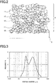
Fig. 2 is a view for describing a structure of a membrane electrode assembly for a polymer electrolyte fuel cell according to an embodiment of the present invention. -
Fig. 3 is a diagram showing a measurement result of a particle size distribution of catalyst ink according to an embodiment of the present invention. - Referring to the drawings, some embodiments of the present invention will be described.
- It should be noted that the present invention is not limited to the embodiments described below but may be modified in design or the like based on the knowledge of a skilled person, and such modifications are also encompassed by the scope of the present invention.
- In the following detailed description, specific details will be explained to provide a complete understanding of the embodiments of the present invention. It is clear, however, that one or more embodiments can be implemented without such details. To simplify the drawings, well-known structures and devices may be schematically illustrated.
- As shown in
Fig. 1 , a pair ofelectrode catalyst layers polymer electrolyte membrane 2 are arranged on both surfaces of thepolymer electrolyte membrane 2 constituting the solidpolymer fuel cell 1. Agas diffusion layer 4A is disposed on the surface of theelectrode catalyst layer 3A opposite to the surface facing thepolymer electrolyte membrane 2, and agas diffusion layer 4F is arranged on the surface of theelectrode catalyst layer 3F opposite to the surface facing thepolymer electrolyte membrane 2 so that thegas diffusion layer 4A and thegas diffusion layer 4F face each other across thepolymer electrolyte membrane 2 and the pair ofelectrode catalyst layers - The
gas diffusion layer 4A has a first surface and a second surface opposed to the first surface. The first surface faces theelectrode catalyst layer 3A. Aseparator 5A has a first major surface and a second major surface. The first major surface faces the second surface of thegas diffusion layer 4A and has formed thereingas flow paths 6A through which reaction gas flows. The second major surface has formed thereincooling water paths 7A through which cooling water passes. Theseparator 5A is disposed at the first major surface thereof on the second surface of thegas diffusion layer 4A. Thegas diffusion layer 4F has a first surface and a second surface opposed to the first surface. The first surface faces theelectrode catalyst layer 3F. Aseparator 5F has a first major surface and a second major surface. The first major surface faces the second surface of thegas diffusion layer 4F and has formed thereingas flow paths 6F through which reaction gas flows. The second major surface has formed thereincooling water paths 7F through which cooling water passes. Theseparator 5F is disposed at the first major surface thereof on the second surface of thegas diffusion layer 4F. Hereinafter, theelectrode catalyst layers electrode catalyst layer 3" when there is no need to distinguish between the two layers. -
Fig. 2 is a schematic cross-sectional view showing an example of a configuration of the electrode catalyst layer according to the present embodiment. As shown inFig. 2 , theelectrode catalyst layer 8 according to the present embodiment is bonded to the surface of thepolymer electrolyte membrane 9. Theelectrode catalyst layer 8 is composed of acatalyst 10,carbon particles 11 as a conductive carrier, apolymer electrolyte 12,carbon fibers 13, andorganic electrolyte fibers 14. Portions of theelectrode catalyst layer 8 where none of thecatalyst 10, thecarbon particles 11, thepolymer electrolyte 12, thecarbon fiber 13, and theorganic electrolyte fiber 14 are present are voids. - Next, a method of producing catalyst ink for forming electrode catalyst layer according to the present embodiment will be described. The catalyst ink for forming the electrode catalyst layer is used for forming the
electrode catalyst layers 3 and 8 (electrode catalyst layer for the solid polymer fuel cell) of the solidpolymer fuel cell 1. - First, to obtain a catalyst particle slurry, the
carbon particles 11 forming the catalyst-supported carbon particles carrying thecatalyst 10 and thepolymer electrolyte 12 are mixed and dispersed in a dispersion medium (in a solvent). - Examples of the
catalyst 10 include metals and alloys of the following metals, and oxides, complex oxides, and carbides of these substances. Examples of metals include platinum group elements (platinum, palladium, ruthenium, iridium, rhodium, and osmium), iron, lead, copper, chromium, cobalt, nickel, manganese, vanadium, molybdenum, gallium, and aluminum. - The
carbon particles 11 may be any type as long as they are conductive and can carry a catalyst without being affected by the catalyst. However, generally, carbon particles are used. - As a dispersion medium (solvent), any one of water or alcohols such as methanol, ethanol, 1-propanol, 2-propanol, 1-butanol, 2-butanol, isobutyl alcohol, tert-butyl alcohol, and pentanol can be used. Further, as the dispersion medium, it is also possible to use a dispersion medium in which two or more of the above dispersion mediums are mixed. For mixing and dispersing, for example, bead mills, planetary mixers, and dissolvers can be used.
- Any material can be used for the
polymer electrolyte membranes polymer electrolyte 12, as long as the material has proton conductivity, and fluorine-based polymer electrolytes and hydrocarbon-based polymer electrolytes can be used. A polymer electrolyte having a tetrafluoroethylene skeleton can be used as the fluorine-based polymer electrolyte. For example, "Nafion (registered trademark)" manufactured by Du Pont may be used. Thepolymer electrolyte 12 is in a state where the polymer electrolyte is aggregated. - Next, at least one of the
carbon fibers 13 andorganic electrolyte fibers 14 is added to the catalyst particle slurry produced by the above method, and mixed and dispersed to obtain a catalyst ink. For mixing and dispersing, for example, bead mills, planetary mixers, and dissolvers can be used. - Examples of the
carbon fiber 13 include carbon fibers, carbon nanotubes, carbon nanohorns, and conductive polymer nanofibers. Only one type of these fibers may be used alone, or two or more types of fibers may be used together. - The
polymer electrolyte 12 and the polymer electrolyte constituting theorganic electrolyte fiber 14 may be formed from the same material or material different from each other. The polymer electrolyte constituting each of thepolymer electrolyte 12 and theorganic electrolyte fiber 14 and the polymer electrolyte constituting thepolymer electrolyte films - The membrane electrode assembly is produced by bonding the
electrode catalyst layer 3 formed of the catalyst ink to both surfaces of thepolymer electrolyte membrane 2. - Examples of a method of bonding the
electrode catalyst layer 3 to thepolymer electrolyte membrane 2 include bonding theelectrode catalyst layer 3 and thepolymer electrolyte membrane 2 by using a transfer substrate having an electrode catalyst layer in which a catalyst ink is applied to the transfer substrate, and to bring the surface of the electrode catalyst layer of the transfer substrate into contact with the electrode catalyst layer having the polymer electrolyte membrane, and then heat and pressure theelectrode catalyst layer 3 and thepolymer electrolyte membrane 2. - However, the use of the above method results in poor adhesion between the
electrode catalyst layer 3 and thepolymer electrolyte membrane 2, and voids are likely to be formed at the interface between theelectrode catalyst layer 3 and thepolymer electrolyte membrane 2. This tends to cause problems such as a decrease in power generation performance due to interfacial resistance, and a decrease in power generation performance due to flooding due to water clogging of the void. - On the other hand, the film electrode assembly can also be produced by a method in which a solvent component (dispersion medium) is removed from the coating film of the catalyst ink after the catalyst ink is directly applied to the surface of the
polymer electrolyte membrane 2. The use of this method is unlikely to cause the above problems because of the good adhesion between theelectrode catalyst layer 3 and thepolymer electrolyte membrane 2. - However, the conventional method of applying the catalytic ink directly to the
polymer electrolyte membrane 2 has the problem that wrinkles or cracks can easily occur in the appliedelectrode catalyst layer 3 due to the swelling of thepolymer electrolyte membrane 2, which can lead to a decrease in power generation performance and durability. - On the other hand, if at least one of the
carbon fibers 13 and theorganic electrolyte fibers 14 is added to the catalyst ink as in the present embodiment, the strength of theelectrode catalyst layer 3 is enhanced. Specifically, the catalyst ink comprising only catalyst-supported carbon particles having a particle diameter in the range of 0.1 µm or more and 1 µm or less undergo aggregation because the catalyst-supported carbon particles are small, and tends to cause wrinkles or cracks in the coatedelectrode catalyst layer 3. Therefore, the present embodiment contributes to the suppression of wrinkles or cracks in theelectrode catalyst layer 3, because aggregation of the catalyst-supported carbon particles having a small particle diameter can be suppressed by adding theabove fibers 13 having a particle diameter in a range of 1 µm or more and 10 µm or less. - If a peak in the range of 0.1 µm or more and 1 µm or less is outside the range of 0.1 µm or more and 1 µm or less in the particle size distribution in the catalyst ink, aggregation cannot be fully controlled, and thus wrinkles or cracks are likely to occur in the coated
electrode catalyst layer 3. - Additionally, if the peak in the range of 1 µm or more and 10 µm or less in the particle size distribution in the catalyst ink is larger than this range, when the coating is applied so that the film becomes thin, the unevenness becomes conspicuous, which may cause damage to the
polymer electrolyte membrane 2. - On the other hand, a catalytic ink consisting only of large particle diameters in the range of 1 µm or more and 10 µm or less will have insufficient specific surface area of the catalyst, resulting in a decrease in the catalytic activity and therefore leading to lower performance.
- If the viscosity of the catalytic ink is high, the coating and drying process becomes difficult, and wrinkles or cracks are likely to occur in the
electrode catalyst layer 3 during the coating and drying process. Specifically, when the thixotropic index (TI value) of the viscosity at a shear rate of 10 (1/s) to the viscosity at a shear rate of 100 (1/s) exceeds 10, coating becomes difficult and wrinkles or cracks are likely to occur. A catalytic ink consisting only of small particle diameters tends to cause agglomeration of particles, and as a result, the TI value becomes high. On the other hand, the catalyst ink formed of small particles having a peak value of the particle size distribution in the range of 0.1 µm to 1 µm and large particles having a peak value of the particle size distribution in the range of 1 µm to 10 µm suppresses agglomeration of the particles and therefore does not have high viscosity, and is less likely to cause wrinkles or cracks when applied to theelectrode catalyst layer 3. - In the catalyst ink of the present embodiment, as described above, the catalyst-supported carbon particles have a peak value of the particle size distribution in the range of 0.1 µm to 1 µm, and the added fibers form a peak value of the particle size distribution in the range of 1 µm to 10 µm. Each of the above peak values can be formed, for example, if the particle size of the target particle is 60% wt or more, preferably 80 wt% or more, within the relevant range, respectively.
- When the solid content concentration of the catalyst ink is higher than 20 wt%, the viscosity becomes high and it becomes difficult to apply a thin film thickness, so that wrinkles or cracks are easily generated when applied to the
electrode catalyst layer 3. - On the other hand, when the viscosity of the catalyst ink is low, specifically, when the thixotropic index (TI value) of a viscosity at a shear rate of 10 (1/s) to a viscosity at a shear rate of 100 (1/s) becomes smaller than 1.5, wrinkles or cracks are likely to occur during the drying process of the catalyst ink when the catalyst ink is applied to the
electrode catalyst layer 3. - The average fiber diameter of the
organic electrolyte fiber 14 is 2 µm or less. When the average fiber diameter is 2 µm or less, appropriate thinness for a fiber material contained in the electrode catalyst layer can be ensured. - In order to improve the output of the polymer electrolyte fuel cell, it is desired that the gas supplied to the electrode catalyst layer is suitably diffused into the electrode catalyst layer through the void in the electrode catalyst layer, and that the water generated through the electrode reaction is appropriately discharged through the void, particularly in the air electrode. The presence of the void facilitates the formation of the interface between the gas, the catalyst-supported carbon and the polymer electrolyte, and promotes the electrode reaction, thereby improving the output of the solid polymer fuel cell.
- From the above viewpoints, the electrode catalyst layer preferably has the void of an appropriate size and amount. When the average fiber diameter of the
polymer electrolyte fibers 14 is 2 µm or less, sufficient gaps are formed in the structure in which thepolymer electrolyte fibers 14 are entangled with each other in the electrode catalyst layer, and thus sufficient quantity of voids is ensured. Accordingly, the output of the fuel cell can be improved. Further, when the average fiber diameter of thepolymer electrolyte fibers 14 is in the range of 0.5 nm or more and 500 nm or less, the output of the fuel cell is particularly increased. - The average fiber length of the
polymer electrolyte fibers 14 is preferably larger than the average fiber diameter and preferably in the range of 1 µm or more and 200 µm or less. When the average fiber length is within the above range, aggregation of thepolymer electrolyte fibers 14 in the electrode catalyst layer is reduced, which facilitates void formation. Further, when the average fiber length is within the above range, since a structure in which thepolymer electrolyte fibers 14 are entangled with each other in the electrode catalyst layer is suitably formed, the electrode catalyst layer has increased strength. Accordingly, the effect of reducing occurrence of cracking is further enhanced. - According to the present embodiment, even when the catalyst ink is directly applied to the polymer electrolyte membrane during the production of the membrane electrode assembly, wrinkles or cracks in the catalyst layer can be suppressed without degrading the power generation performance. As a result, it is possible to produce a membrane electrode assembly having good power generation performance without lowering the yield.
- Examples and comparative examples of the present invention will now be described.
- Example 1 of the present invention will be described below.
- Catalyst-supported carbon particles (trade name: TEC10E50E, manufactured by TANAKA Kikinzoku Kogyo K.K.) supporting 50 wt% platinum and a dispersion of polymer electrolyte (trade name: Nafion dispersion, manufactured by FUJIFILM Wako Pure Chemical Corporation) were mixed with water in a planetary mixer to prepare a catalyst particle slurry.
- Carbon fibers (Trade name: VGCF-H, manufactured by Showa Denko K.K.) and 1-propanol were added to the above catalyst particle slurry, adjusted to a solid content concentration of 10 wt%, and dispersed by a bead mill disperser to obtain a catalyst ink.
- The measurement result of the particle size distribution of the catalyst ink was as shown in
Fig. 3 , that is, the catalyst ink of Example 1 was a catalyst ink having a particle size distribution having a peak in the range of 0.1 µm to 1 µm and a peak in the range of 1 µm to 10 µm. - The catalyst ink of Example 1 had a TI value of 6.0 as a result of measuring the ratio of the viscosity at a shear rate of 10 (1/s) and the viscosity at a shear rate of 100 (1/s).
- Here, the measurement of the particle size distribution in the catalyst ink of the present specification is performed by the laser diffraction and scattering method.
- The measurement conditions were as follows:
Measurement conditions: - Permeability of sample: Absorbed
- Refractive index of solvent: 1.333
- The measurement of the shear rate (viscosity measuring method) of the present specification is performed under the following conditions.
- Measurement conditions:
- Measuring device: Cone plate type viscometer
- Measurement range (shear rate): 1000 [1/s] to 1 [1/s]
- Measurement temperature: 23°C
- The TI value is the ratio of viscosity.
- The TI values in the present specification are defined as follows.

- Next, the catalyst ink was directly applied to both surfaces of the polymer electrolyte membrane by the die coating method to obtain a membrane electrode assembly.
- The catalyst ink of Example 1 did not cause wrinkles or cracks in the catalyst layer when directly applied to both surfaces of the polymer electrolyte membrane, and obtained good power generation performance.
- Example 2 of the present invention will be described below.
- The catalyst ink of Example 2 was obtained by a process similar to that of Example 1, except that polymer electrolyte fibers were added to the catalyst ink instead of carbon fibers.
- Polymer electrolyte fibers were prepared by forming a polymer electrolyte dispersion (Nafion dispersion: manufactured by FUJIFILM Wako Pure Chemical Corporation) into a fibrous state using the electrospinning method, followed by cooling and pulverizing. The average fiber diameter of the polymer electrolyte fibers was 150 nm and the average fiber length was 10 µm.
- The measurement result of the particle size distribution of the catalyst ink of Example 2 showed two peaks, one of which is a peak in a range of 0.1 µm to 1 µm and the other a peak in a range of 1 µm to 10 µm.
- The catalyst ink of Example 2 had a TI value of 7.5 as a result of measuring the ratio of the viscosity at a shear rate of 10 (1/s) and the viscosity at a shear rate of 100 (1/s).
- The catalyst ink of Example 2 did not cause wrinkles or cracks in the catalyst layer when directly applied to both surfaces of the polymer electrolyte membrane, and obtained good power generation performance.
- Example 3 of the present invention will be described below.
- The catalyst ink of Example 3 was obtained by a process similar to that of Example 1, except that the polymer electrolyte fibers of Example 2 were added after the carbon fibers of Example 1 was added.
- The measurement result of the particle size distribution of the catalyst ink of Example 3 showed a peak in a range of 0.1 µm to 1 µm and a peak in a range of 1 µm to 10 µm.
- The catalyst ink of Example 3 had a TI value of 4.5 as a result of measuring the ratio of the viscosity at a shear rate of 10 (1/s) and the viscosity at a shear rate of 100 (1/s).
- The catalyst ink of Example 3 did not cause wrinkles or cracks in the catalyst layer when directly applied to both surfaces of the polymer electrolyte membrane, and obtained good power generation performance.
- The catalyst ink of Comparative Example 1 was obtained by a process similar to that of Example 1, except that no carbon fibers were added to the catalyst ink.
- In the measurement result of the particle size distribution of the catalyst ink of Comparative Example 1, one peak in the range of 0.1 µm to 1 µm appeared.
- The catalyst ink of Comparative Example 1 had a TI value of 11.0 as a result of measuring the ratio of the viscosity at a shear rate of 10 (1/s) and the viscosity at a shear rate of 100 (1/s).
- The catalyst ink of Comparative Example 1 resulted in the occurrence of wrinkles or cracks in the catalyst layer when directly applied to both surfaces of the polymer electrolyte membrane.
- The catalyst ink of Comparative Example 2 was obtained by a process similar to that of Example 1, except that the catalyst ink was produced so that the solid content concentration was 5 wt%.
- The measurement result of the particle size distribution of the catalyst ink of Comparative Example 2 showed two peaks, one of which is a peak in a range of 0.1 µm to 1 µm and the other a peak in a range of 1 µm to 10 µm.
The catalyst ink of Comparative Example 2 had a TI value of 1.0 as a result of measuring the ratio of the viscosity at a shear rate of 10 (1/s) and the viscosity at a shear rate of 100 (1/s). - The catalyst ink of Comparative Example 2 resulted in the occurrence of wrinkles or cracks in the catalyst layer when directly applied to both surfaces of the polymer electrolyte membrane.
- A catalyst ink of Comparative Example 2 were obtained in the process similar to that of Example 2, except that polymer electrolyte fibers having an average fiber diameter of 3.0 µm and an average fiber length of 20 µm were used as the polymer electrolyte fibers.
- The measurement result of the particle size distribution of the catalyst ink of Comparative Example 3 showed two peaks, one of which is a peak in a range of 0.1 µm to 1 µm and the other a peak in a range of 1 µm to 10 µm.
- The above-described catalyst ink had a TI value of 6.0 as a result of measuring the ratio of the viscosity at a shear rate of 10 (1/s) and the viscosity at a shear rate of 100 (1/s).
- The catalyst ink of Comparative Example 3 did not cause wrinkles or cracks in the catalyst layer when directly applied to both surfaces of the polymer electrolyte membrane, but resulted in a slight decrease in power generation performance.
- The scope of the present invention is not limited to the illustrated and described exemplary embodiments, but includes all embodiments that provide effects equivalent to the intended effects of the present invention. Furthermore, the scope of the present invention is not limited to combinations of features recited in the claims, but may be defined by any desired combination of specific features among all the disclosed features.
- This application claims the benefit of priority from
Japanese Patent Application No. 2019-222431 (filed on December 9, 2019 -
- 1
- Polymer electrolyte fuel cell
- 2, 9
- Polymer electrolyte membrane
- 3, 8
- Electrode catalyst layer
- 3A, 3F
- Electrode catalyst layer
- 10
- Catalyst
- 11
- Carbon particle
- 12
- Polymer electrolyte
- 13
- Carbon fiber
- 14
- organic electrolyte fiber
Claims (6)
- A catalyst ink for forming an electrode catalyst layer comprising:a solvent which contains catalyst-supported carbon particles which include carbon particles supporting a catalyst, a polymer electrolyte, and at least one selected from carbon fibers and organic electrolyte fibers, whereinthe solvent has a particle size distribution in which a first peak lies in a range of 0.1 µm or more and 1 µm or less, and a second peak lies in a range of 1 µm or more and 10 µm or less.
- The catalyst ink for forming an electrode catalyst layer according to claim 1, wherein a solid content concentration is 8 wt% or more and 20 wt% or less, and wherein
a thixotropic index (TI value) of a first viscosity at a shear rate of 10 (1/s) to a second viscosity at a shear rate of 100 (1/s) is 1.5 or more and 10 or less. - The catalyst ink for forming an electrode catalyst layer according to claim 1 or 2, wherein the catalyst ink contains one or more kinds selected from carbon nanofibers and carbon nanotubes as the carbon fibers.
- The catalyst ink according to claim 1, wherein the organic electrolyte fibers have an average fiber diameter of 2 µm or less, and an average fiber length of 1 µm or more and 200 µm or less.
- A membrane electrode assembly using the catalyst ink for forming an electrode catalyst layer according to claims 1 to 4.
- A method of producing a membrane electrode assembly in which a catalyst ink is directly applied to a polymer electrolyte membrane to produce the membrane electrode assembly, wherein
the catalyst ink for forming an electrode catalyst layer according to any one of claims 1 to 4 is used as the catalyst ink.
Applications Claiming Priority (2)
| Application Number | Priority Date | Filing Date | Title |
|---|---|---|---|
| JP2019222431 | 2019-12-09 | ||
| PCT/JP2020/044388 WO2021117522A1 (en) | 2019-12-09 | 2020-11-27 | Catalyst ink for use in forming electrode catalyst layer, and method for producing membrane electrode assembly |
Publications (2)
| Publication Number | Publication Date |
|---|---|
| EP4075550A1 true EP4075550A1 (en) | 2022-10-19 |
| EP4075550A4 EP4075550A4 (en) | 2024-07-24 |
Family
ID=76330195
Family Applications (1)
| Application Number | Title | Priority Date | Filing Date |
|---|---|---|---|
| EP20898969.9A Pending EP4075550A4 (en) | 2019-12-09 | 2020-11-27 | CATALYST INK FOR USE IN THE PRODUCTION OF AN ELECTRODE CATALYST LAYER AND METHOD FOR THE PRODUCTION OF A MEMBRANE-ELECTRODE ASSEMBLY |
Country Status (5)
| Country | Link |
|---|---|
| US (1) | US12418032B2 (en) |
| EP (1) | EP4075550A4 (en) |
| JP (2) | JP7652081B2 (en) |
| CN (1) | CN114902451A (en) |
| WO (1) | WO2021117522A1 (en) |
Families Citing this family (1)
| Publication number | Priority date | Publication date | Assignee | Title |
|---|---|---|---|---|
| FR3148119B1 (en) * | 2023-04-18 | 2025-09-12 | Symbio France | Fuel cell electrode ink, preparation method for such an ink and an electrode, and fuel cell incorporating such an electrode |
Family Cites Families (12)
| Publication number | Priority date | Publication date | Assignee | Title |
|---|---|---|---|---|
| JPH08227716A (en) * | 1995-02-22 | 1996-09-03 | Tanaka Kikinzoku Kogyo Kk | Raw material for electrode of polymer solid oxide fuel cell and method for producing the same |
| JP3617237B2 (en) * | 1997-02-21 | 2005-02-02 | トヨタ自動車株式会社 | ELECTRODE FOR FUEL CELL, POWER GENERATION LAYER AND METHOD FOR PRODUCING THE SAME |
| TW525314B (en) | 2000-09-29 | 2003-03-21 | Sony Corp | Fuel cell and method for preparation thereof |
| JP4131408B2 (en) * | 2004-02-13 | 2008-08-13 | アイシン精機株式会社 | Method for producing polymer electrolyte fuel cell |
| JP2007220416A (en) | 2006-02-15 | 2007-08-30 | Aisin Seiki Co Ltd | FUEL CELL ELECTRODE AND METHOD FOR PRODUCING FUEL CELL ELECTRODE |
| JP5537178B2 (en) * | 2010-02-05 | 2014-07-02 | 本田技研工業株式会社 | Membrane electrode structure for fuel cell and manufacturing method thereof |
| JP5790537B2 (en) * | 2012-02-16 | 2015-10-07 | トヨタ自動車株式会社 | Method for producing catalyst ink |
| JP6459429B2 (en) * | 2014-11-25 | 2019-01-30 | 凸版印刷株式会社 | Catalyst ink for forming electrode catalyst layer for polymer electrolyte fuel cell, and method for producing polymer electrolyte fuel cell |
| JP6554954B2 (en) * | 2015-07-13 | 2019-08-07 | 日産自動車株式会社 | Catalyst mixture, production method thereof, and electrode catalyst layer, membrane electrode assembly, and fuel cell using the catalyst mixture |
| JP6638675B2 (en) * | 2017-03-03 | 2020-01-29 | トヨタ自動車株式会社 | Fuel cell catalyst ink, fuel cell catalyst layer, and membrane electrode assembly |
| EP3694037A4 (en) | 2017-10-02 | 2020-11-25 | Toppan Printing Co., Ltd. | ELECTRODE CATALYST LAYER, MEMBRANE ELECTRODE ARRANGEMENT AND SOLID POLYMER FUEL CELL |
| JP7020061B2 (en) * | 2017-11-01 | 2022-02-16 | 凸版印刷株式会社 | Catalyst ink |
-
2020
- 2020-11-27 EP EP20898969.9A patent/EP4075550A4/en active Pending
- 2020-11-27 JP JP2021563858A patent/JP7652081B2/en active Active
- 2020-11-27 CN CN202080082948.XA patent/CN114902451A/en active Pending
- 2020-11-27 WO PCT/JP2020/044388 patent/WO2021117522A1/en not_active Ceased
-
2022
- 2022-06-02 US US17/830,585 patent/US12418032B2/en active Active
-
2025
- 2025-03-14 JP JP2025040801A patent/JP7786632B2/en active Active
Also Published As
| Publication number | Publication date |
|---|---|
| WO2021117522A1 (en) | 2021-06-17 |
| CN114902451A (en) | 2022-08-12 |
| JP7652081B2 (en) | 2025-03-27 |
| US20220302465A1 (en) | 2022-09-22 |
| US12418032B2 (en) | 2025-09-16 |
| JP7786632B2 (en) | 2025-12-16 |
| JP2025087899A (en) | 2025-06-10 |
| JPWO2021117522A1 (en) | 2021-06-17 |
| EP4075550A4 (en) | 2024-07-24 |
Similar Documents
| Publication | Publication Date | Title |
|---|---|---|
| EP3536664B1 (en) | Method for manufacturing electrode, electrode manufactured thereby, membrane-electrode assembly comprising same electrode, and fuel cell including same membrane-electrode assembly | |
| JP5213499B2 (en) | Fuel cell | |
| WO2019069789A1 (en) | Electrode catalyst layer, membrane electrode assembly, and solid polymer-type fuel cell | |
| CN101416333A (en) | Fuel cell membrane electrode assembly and method for producing same | |
| EP3547430A1 (en) | Membrane electrode assembly for solid polymer fuel cell, and solid polymer fuel cell | |
| JP7786632B2 (en) | Catalyst ink for forming electrode catalyst layer and method for manufacturing membrane electrode assembly | |
| JP7589762B2 (en) | Membrane electrode assembly for polymer electrolyte fuel cell, polymer electrolyte fuel cell, and method for manufacturing membrane electrode assembly for polymer electrolyte fuel cell | |
| JP2006339124A (en) | Membrane electrode assembly for fuel cell and polymer electrolyte fuel cell using the same | |
| JP6432703B1 (en) | Membrane electrode assembly for polymer electrolyte fuel cell, polymer electrolyte fuel cell, and method for producing membrane electrode assembly for polymer electrolyte fuel cell | |
| EP4216321A1 (en) | Electrode catalyst layer, membrane electrode assembly, and solid polymer-type fuel cell | |
| US20210167400A1 (en) | Membrane electrode assembly and fuel cell | |
| JP6554954B2 (en) | Catalyst mixture, production method thereof, and electrode catalyst layer, membrane electrode assembly, and fuel cell using the catalyst mixture | |
| JP2005108827A (en) | Catalyst layer forming ink, electrode using the same, and membrane electrode assembly | |
| JP2022162112A (en) | Catalyst ink for forming electrode catalyst layer of polymer electrolyte fuel cell, method for producing membrane electrode assembly, membrane electrode assembly, and polymer electrolyte fuel cell | |
| JP7484888B2 (en) | Catalyst layer for polymer electrolyte fuel cell, membrane electrode assembly, and polymer electrolyte fuel cell | |
| JP7067136B2 (en) | Catalyst layer, membrane electrode assembly, polymer electrolyte fuel cell | |
| EP4220781A1 (en) | Electrode catalyst layer and membrane electrode assembly | |
| US20230411640A1 (en) | Membrane electrode assembly and polymer electrolyte fuel cell | |
| JP7140256B2 (en) | Electrocatalyst layer | |
| JP2009245932A (en) | Electrode catalyst ink for fuel cell, electrode catalyst layer, membrane-electrode assembly, and polymer electrolyte fuel cell | |
| JP2022168133A (en) | Electrode catalyst layer, membrane electrode assembly and polymer electrolyte fuel cell | |
| CN116508179A (en) | Electrode catalyst layer, membrane electrode assembly, and solid polymer fuel cell | |
| JP2022095263A (en) | Catalyst ink for polymer electrolyte fuel cell, catalyst layer for polymer electrolyte fuel cell, and membrane-electrode assembly for polymer electrolyte fuel cell | |
| JP2011204605A (en) | Electrode catalytic layer for fuel cell, membrane electrode assembly for fuel cell comprising the electrode catalytic layer, fuel cell comprising the membrane electrode assembly, and method of manufacturing the electrode catalytic layer for fuel cell |
Legal Events
| Date | Code | Title | Description |
|---|---|---|---|
| STAA | Information on the status of an ep patent application or granted ep patent |
Free format text: STATUS: THE INTERNATIONAL PUBLICATION HAS BEEN MADE |
|
| PUAI | Public reference made under article 153(3) epc to a published international application that has entered the european phase |
Free format text: ORIGINAL CODE: 0009012 |
|
| STAA | Information on the status of an ep patent application or granted ep patent |
Free format text: STATUS: REQUEST FOR EXAMINATION WAS MADE |
|
| 17P | Request for examination filed |
Effective date: 20220520 |
|
| AK | Designated contracting states |
Kind code of ref document: A1 Designated state(s): AL AT BE BG CH CY CZ DE DK EE ES FI FR GB GR HR HU IE IS IT LI LT LU LV MC MK MT NL NO PL PT RO RS SE SI SK SM TR |
|
| DAV | Request for validation of the european patent (deleted) | ||
| DAX | Request for extension of the european patent (deleted) | ||
| A4 | Supplementary search report drawn up and despatched |
Effective date: 20240624 |
|
| RIC1 | Information provided on ipc code assigned before grant |
Ipc: H01M 4/92 20060101ALI20240618BHEP Ipc: H01M 4/90 20060101ALI20240618BHEP Ipc: H01M 8/10 20160101ALI20240618BHEP Ipc: H01M 4/96 20060101ALI20240618BHEP Ipc: H01M 4/88 20060101ALI20240618BHEP Ipc: H01M 4/86 20060101AFI20240618BHEP |