EP4075463B1 - Operating mechanism - Google Patents
Operating mechanism Download PDFInfo
- Publication number
- EP4075463B1 EP4075463B1 EP22168576.1A EP22168576A EP4075463B1 EP 4075463 B1 EP4075463 B1 EP 4075463B1 EP 22168576 A EP22168576 A EP 22168576A EP 4075463 B1 EP4075463 B1 EP 4075463B1
- Authority
- EP
- European Patent Office
- Prior art keywords
- contact
- cam
- locking lever
- shaft
- operating mechanism
- Prior art date
- Legal status (The legal status is an assumption and is not a legal conclusion. Google has not performed a legal analysis and makes no representation as to the accuracy of the status listed.)
- Active
Links
Images

Classifications
-
- H—ELECTRICITY
- H01—ELECTRIC ELEMENTS
- H01H—ELECTRIC SWITCHES; RELAYS; SELECTORS; EMERGENCY PROTECTIVE DEVICES
- H01H5/00—Snap-action arrangements, i.e. in which during a single opening operation or a single closing operation energy is first stored and then released to produce or assist the contact movement
- H01H5/04—Energy stored by deformation of elastic members
- H01H5/06—Energy stored by deformation of elastic members by compression or extension of coil springs
- H01H5/10—Energy stored by deformation of elastic members by compression or extension of coil springs one end of spring being fixedly connected to the stationary or movable part of the switch and the other end reacting with a movable or stationary rigid member respectively through pins, cams, toothed or other shaped surfaces
-
- H—ELECTRICITY
- H01—ELECTRIC ELEMENTS
- H01H—ELECTRIC SWITCHES; RELAYS; SELECTORS; EMERGENCY PROTECTIVE DEVICES
- H01H3/00—Mechanisms for operating contacts
- H01H3/22—Power arrangements internal to the switch for operating the driving mechanism
- H01H3/30—Power arrangements internal to the switch for operating the driving mechanism using spring motor
- H01H3/3031—Means for locking the spring in a charged state
-
- H—ELECTRICITY
- H01—ELECTRIC ELEMENTS
- H01H—ELECTRIC SWITCHES; RELAYS; SELECTORS; EMERGENCY PROTECTIVE DEVICES
- H01H19/00—Switches operated by an operating part which is rotatable about a longitudinal axis thereof and which is acted upon directly by a solid body external to the switch, e.g. by a hand
- H01H19/54—Switches operated by an operating part which is rotatable about a longitudinal axis thereof and which is acted upon directly by a solid body external to the switch, e.g. by a hand the operating part having at least five or an unspecified number of operative positions
- H01H19/60—Angularly-movable actuating part carrying no contacts
- H01H19/62—Contacts actuated by radial cams
- H01H19/626—Contacts actuated by radial cams actuating bridging contacts
-
- H—ELECTRICITY
- H01—ELECTRIC ELEMENTS
- H01H—ELECTRIC SWITCHES; RELAYS; SELECTORS; EMERGENCY PROTECTIVE DEVICES
- H01H3/00—Mechanisms for operating contacts
- H01H3/22—Power arrangements internal to the switch for operating the driving mechanism
- H01H3/30—Power arrangements internal to the switch for operating the driving mechanism using spring motor
- H01H3/3005—Charging means
- H01H3/3015—Charging means using cam devices
-
- H—ELECTRICITY
- H01—ELECTRIC ELEMENTS
- H01H—ELECTRIC SWITCHES; RELAYS; SELECTORS; EMERGENCY PROTECTIVE DEVICES
- H01H3/00—Mechanisms for operating contacts
- H01H3/32—Driving mechanisms, i.e. for transmitting driving force to the contacts
- H01H3/42—Driving mechanisms, i.e. for transmitting driving force to the contacts using cam or eccentric
-
- H—ELECTRICITY
- H01—ELECTRIC ELEMENTS
- H01H—ELECTRIC SWITCHES; RELAYS; SELECTORS; EMERGENCY PROTECTIVE DEVICES
- H01H3/00—Mechanisms for operating contacts
- H01H3/22—Power arrangements internal to the switch for operating the driving mechanism
- H01H3/30—Power arrangements internal to the switch for operating the driving mechanism using spring motor
- H01H3/3031—Means for locking the spring in a charged state
- H01H2003/3036—Means for locking the spring in a charged state using of balls or rollers in the locking device
-
- H—ELECTRICITY
- H01—ELECTRIC ELEMENTS
- H01H—ELECTRIC SWITCHES; RELAYS; SELECTORS; EMERGENCY PROTECTIVE DEVICES
- H01H71/00—Details of the protective switches or relays covered by groups H01H73/00 - H01H83/00
- H01H71/10—Operating or release mechanisms
Definitions
- the invention relates to an operating mechanism for opening and closing at least one contact, according to the preamble of claim 1.
- EP 0 302 721 A2 A discloses a switch assembly suitable for use as part of an overall electrical circuit breaker.
- the assembly includes a three-link arrangement consisting of three links interconnected together for movement between a first positional configuration in order to open a circuit and a second positional configuration in order to close the circuit.
- Means is provided for applying a force to the arrangement in a way which causes the links to move from their first positional configuration to their second positional configuration, and thereafter for maintaining the links in their second positional configuration.
- An arrangement separate from the force-applying mechanism and including one of the three links is also provided for automatically overriding the application of force to the arrangement in order to cause the links to immediately move back to their first configuration, either during movement to their second configuration or after the links have been moved into their second configuration by the force-applying mechanism, whereby the switch assembly can be tripped back to its open position at any time.
- US 4 409 449 A discloses an operating mechanism for use in a circuit breaker having a stationary contact and a moving contact which is turned on (closed) or off (tripped open) by using the accumulated energy of a stretched spring.
- the operating mechanism has a frame, a main shaft having a closing cam and an additional cam, a four-joint crank for actuating the moving contact in accordance with the movement of the main cam, a roller clutch mounted around the shaft, a bearing fitting member having an opening mounted around the roller clutch, a gear member having a stud adapted to fit within the opening of the fitting member, and an electric motor and a manually operable handle to drive the spring to accumulate energy.
- CN 205 159 204 U discloses an indoor high-voltage vacuum circuit breaker spring operating mechanism.
- WO 2018/115026 A1 discloses a mechanism for opening and closing a circuit breaker having an operating rod for moving the contacts of the circuit breaker between an open position and a closed position.
- the mechanism comprises a frame; a first rod hingedly arranged with one end to the frame; a second rod hingedly arranged with one end to the other end of the first rod and arranged with the other end slidable to the frame between a contact open position and a contact closed position in a direction substantially perpendicular to the direction of movement of the other end of the first rod.
- a spring could also be arranged to the cam, wherein the spring is energized at a certain level and then released to complete the closing operation.
- the spring is used for achieving the right speed and contact force. If the cam is used to keep the rod mechanism in closed position, the spring cannot be reenergized until the cam is rotated to open the contact.
- the D-shaft portion in combination with the locking lever provides a lock for the rod mechanism, such that the contact can be kept in closed position, while the cam can be rotated further.
- the D-shaft portion only has to be rotated to release the rod mechanism.
- the cam can be rotated further, while the contact is maintained in the closed position, a spring provided to assist in the closing movement, can already be reenergized directly after the closing movement is completed.
- a first spring is coupled to the control shaft and arranged to urge the control shaft into the lock position.
- a roller is arranged on the locking lever, wherein the roller forms the second end of the locking lever.
- the roller reduces any friction with the D-shaft portion and improves the urging by the locking lever of the D-shaft portion in the pass position.
- a cam follower is arranged on the hinging axis of the first ends of the first and second links and wherein the cam follower is configured to be in contact with the cam.
- the cam follower reduces friction and wear between the cam and the rod mechanism.
- the profile of the cam has a closing profile section for urging the rod mechanism in a stretched position in which the bridge is in the closed position, an opening profile section for letting the rod mechanism fold and an idle profile section, further comprising a closing spring for urging the closing profile section of the cam in contact with the hinging axis of the first ends of the two links.
- Figure 1 shows an operating mechanism 1 for opening and closing a contact.
- the operating mechanism 1 has a base frame (not shown) and a bridge body 3 with which operating rods of contacts can be operated.
- a cam follower 6 is provided at this hinge axis.
- the first link 4 is hinged with the other end 7 to the base frame and the second link 5 is hinged with the other end 8 to the bridge body 3.
- a camshaft 9 with a cam 10 is provided in operating contact with the cam follower 6 to urge the rod mechanism 4, 5 in a stretched position in which the contacts are closed and a collapsed position in which the contacts are opened.
- a closing spring 11 is connected to the camshaft 9 to assist in the closing movement.
- a locking lever 12 is fixedly arranged to the first link 4 and provided with a roller 13 on the free end of the locking lever 12.
- a control shaft 14 with a D-shaft portion 15 is provided adjacent the roller 13, to lock the locking lever 12 when the rod mechanism 4, 5 is stretched and the contacts are closed.
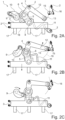
- FIG 2A shows the operating mechanism 1 as shown in figure 1 in more schematic view.
- the bridge body 3 is in a raised position, such that contacts 17 arranged against the contact surface 18 of the bridge body 3 are in an open position.
- the rod mechanism 4, 5 is collapsed position and the locking lever 12 is rotated away from the D-shaft portion 15, which is urged by a spring 16.
- Figure 2C shows the position of the bridge body 3 in closed position, in which the contacts 17 are also closed.
- the locking lever 12 with roller 13 has passed the D-shaft portion 15, which is rotated by the spring 16 in the lock position, which prevents the rod mechanism 4, 5 to return to the position of figure 2A .
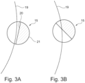
- Figure 3A shows the D-shaft portion 15.
- the cross-section has a circumference with a straight portion 20 and a semi cylindrical portion 21.
- the path 19 of the locking lever 12 is positioned outside of the cross-section of the D-shaft portion 15.
- Figure 3A shows the D-shaft portion 15 in the lock position, where the path 19 intersects with the cross-section of the D-shaft portion 15.
Landscapes
- Mechanisms For Operating Contacts (AREA)
- Driving Mechanisms And Operating Circuits Of Arc-Extinguishing High-Tension Switches (AREA)
- Mechanical Control Devices (AREA)
- Specific Sealing Or Ventilating Devices For Doors And Windows (AREA)
- Operating, Guiding And Securing Of Roll- Type Closing Members (AREA)
Applications Claiming Priority (1)
| Application Number | Priority Date | Filing Date | Title |
|---|---|---|---|
| GB2105356.6A GB2605822B (en) | 2021-04-15 | 2021-04-15 | Operating mechanism |
Publications (2)
| Publication Number | Publication Date |
|---|---|
| EP4075463A1 EP4075463A1 (en) | 2022-10-19 |
| EP4075463B1 true EP4075463B1 (en) | 2025-05-28 |
Family
ID=76377653
Family Applications (1)
| Application Number | Title | Priority Date | Filing Date |
|---|---|---|---|
| EP22168576.1A Active EP4075463B1 (en) | 2021-04-15 | 2022-04-14 | Operating mechanism |
Country Status (6)
| Country | Link |
|---|---|
| US (1) | US11955299B2 (pl) |
| EP (1) | EP4075463B1 (pl) |
| JP (1) | JP7329655B2 (pl) |
| GB (1) | GB2605822B (pl) |
| PL (1) | PL4075463T3 (pl) |
| ZA (1) | ZA202204245B (pl) |
Families Citing this family (2)
| Publication number | Priority date | Publication date | Assignee | Title |
|---|---|---|---|---|
| CN113867248B (zh) * | 2021-09-18 | 2023-10-17 | 北京理工大学 | 一种基于多级凸轮互锁结构的多级联锁电路 |
| CN118571722B (zh) * | 2024-05-07 | 2024-11-22 | 昆山盛英电气有限公司 | 一种智能电网配电的分隔灭弧装置及低压柜 |
Family Cites Families (10)
| Publication number | Priority date | Publication date | Assignee | Title |
|---|---|---|---|---|
| JPS55108118A (en) * | 1979-02-13 | 1980-08-19 | Tokyo Shibaura Electric Co | Motorrdriven spring operating device for circuit breaker |
| US4791250A (en) * | 1987-08-06 | 1988-12-13 | Square D Company | Trip-free, three-link switch assembly |
| JP3441837B2 (ja) * | 1995-04-24 | 2003-09-02 | 三菱電機株式会社 | 開閉装置の操作機構 |
| KR100326725B1 (ko) * | 1997-08-26 | 2002-03-12 | 가나이 쓰도무 | 차단기 |
| DE10120783C1 (de) * | 2001-04-23 | 2002-11-14 | Siemens Ag | Schaltschloss zum Verklinken eines Federspeichers |
| US7449653B2 (en) * | 2007-03-29 | 2008-11-11 | Eaton Corporation | Positive resetting close latch for closing electrical switching apparatus |
| US8063328B2 (en) * | 2009-09-16 | 2011-11-22 | Eaton Corporation | Electrical switching apparatus and charging assembly therefor |
| CN205159204U (zh) * | 2015-12-07 | 2016-04-13 | 武汉大学 | 一种户内高压真空断路器弹簧操动机构 |
| WO2018115026A1 (en) * | 2016-12-23 | 2018-06-28 | Eaton Industries (Austria) Gmbh | Mechanism for opening and closing a circuit breaker |
| FR3090188B1 (fr) * | 2018-12-14 | 2022-02-04 | Schneider Electric Ind Sas | Appareil de coupure d’un courant électrique |
-
2021
- 2021-04-15 GB GB2105356.6A patent/GB2605822B/en not_active Expired - Fee Related
-
2022
- 2022-04-14 ZA ZA2022/04245A patent/ZA202204245B/en unknown
- 2022-04-14 PL PL22168576.1T patent/PL4075463T3/pl unknown
- 2022-04-14 EP EP22168576.1A patent/EP4075463B1/en active Active
- 2022-04-15 JP JP2022067456A patent/JP7329655B2/ja active Active
- 2022-04-15 US US17/659,430 patent/US11955299B2/en active Active
Also Published As
| Publication number | Publication date |
|---|---|
| GB2605822A (en) | 2022-10-19 |
| GB2605822B (en) | 2023-05-31 |
| ZA202204245B (en) | 2024-09-25 |
| JP2022164630A (ja) | 2022-10-27 |
| PL4075463T3 (pl) | 2025-08-04 |
| GB202105356D0 (en) | 2021-06-02 |
| US20220336163A1 (en) | 2022-10-20 |
| US11955299B2 (en) | 2024-04-09 |
| EP4075463A1 (en) | 2022-10-19 |
| JP7329655B2 (ja) | 2023-08-18 |
Similar Documents
| Publication | Publication Date | Title |
|---|---|---|
| EP4075463B1 (en) | Operating mechanism | |
| DE69405602T2 (de) | Fernbetätigter Leistungsschalter mit Rückstellnockenscheibe | |
| US7341290B2 (en) | Lock for vehicle doors or lids | |
| EP1205619B1 (en) | Locking controller of a sliding door | |
| KR20070046910A (ko) | 차량의 도어 또는 리드용 로크 | |
| CA2714920C (en) | Electrical switching apparatus and charging assembly therefor | |
| JPH0628961A (ja) | 配線用遮断器の操作機構 | |
| KR20010042142A (ko) | 회전형 캐치를 구비한 자동차용 도어록 | |
| CN101436471B (zh) | 电开关设备单元及其操作装置 | |
| KR930009105B1 (ko) | 스위치 어셈블리용 2절링크식 무트립 작동기구 | |
| EP0302721A2 (en) | Switch assembly | |
| CN1033833C (zh) | 用于一相线和中线电路断路器的带摆动杆的操纵机构 | |
| KR20250036163A (ko) | 자동차 래치, 특히 자동차 도어 래치 | |
| EP3996123A1 (en) | Operating mechanism for operating at least one contact | |
| CN221508003U (zh) | 电气开关 | |
| KR0157003B1 (ko) | 부하개폐기의 조작장치 | |
| EP4075465A1 (en) | Operating mechanism for a switch | |
| EP1913615B1 (de) | Spannvorrichtung | |
| EP0965717A2 (en) | Device for the quick release of gate wings | |
| WO2018050784A1 (en) | Mechanism for opening and closing a circuit breaker | |
| JPS6333447Y2 (pl) | ||
| CN114220717A (zh) | 一种分合闸机构 | |
| EP0606200A1 (en) | Rotary switch mechanism | |
| JPH071549U (ja) | 開閉装置の操作ロッド | |
| JPH05266766A (ja) | 回路遮断器の駆動装置 |
Legal Events
| Date | Code | Title | Description |
|---|---|---|---|
| PUAI | Public reference made under article 153(3) epc to a published international application that has entered the european phase |
Free format text: ORIGINAL CODE: 0009012 |
|
| STAA | Information on the status of an ep patent application or granted ep patent |
Free format text: STATUS: REQUEST FOR EXAMINATION WAS MADE |
|
| 17P | Request for examination filed |
Effective date: 20220414 |
|
| AK | Designated contracting states |
Kind code of ref document: A1 Designated state(s): AL AT BE BG CH CY CZ DE DK EE ES FI FR GB GR HR HU IE IS IT LI LT LU LV MC MK MT NL NO PL PT RO RS SE SI SK SM TR |
|
| P01 | Opt-out of the competence of the unified patent court (upc) registered |
Effective date: 20230521 |
|
| GRAP | Despatch of communication of intention to grant a patent |
Free format text: ORIGINAL CODE: EPIDOSNIGR1 |
|
| STAA | Information on the status of an ep patent application or granted ep patent |
Free format text: STATUS: GRANT OF PATENT IS INTENDED |
|
| RIC1 | Information provided on ipc code assigned before grant |
Ipc: H01H 71/10 20060101ALN20241028BHEP Ipc: H01H 3/30 20060101ALI20241028BHEP Ipc: H01H 5/10 20060101AFI20241028BHEP |
|
| INTG | Intention to grant announced |
Effective date: 20241107 |
|
| GRAS | Grant fee paid |
Free format text: ORIGINAL CODE: EPIDOSNIGR3 |
|
| GRAA | (expected) grant |
Free format text: ORIGINAL CODE: 0009210 |
|
| STAA | Information on the status of an ep patent application or granted ep patent |
Free format text: STATUS: THE PATENT HAS BEEN GRANTED |
|
| AK | Designated contracting states |
Kind code of ref document: B1 Designated state(s): AL AT BE BG CH CY CZ DE DK EE ES FI FR GB GR HR HU IE IS IT LI LT LU LV MC MK MT NL NO PL PT RO RS SE SI SK SM TR |
|
| REG | Reference to a national code |
Ref country code: GB Ref legal event code: FG4D |
|
| REG | Reference to a national code |
Ref country code: CH Ref legal event code: EP |
|
| REG | Reference to a national code |
Ref country code: DE Ref legal event code: R096 Ref document number: 602022015117 Country of ref document: DE |
|
| REG | Reference to a national code |
Ref country code: IE Ref legal event code: FG4D |
|
| REG | Reference to a national code |
Ref country code: SE Ref legal event code: TRGR |
|
| REG | Reference to a national code |
Ref country code: NL Ref legal event code: FP |
|
| PG25 | Lapsed in a contracting state [announced via postgrant information from national office to epo] |
Ref country code: ES Free format text: LAPSE BECAUSE OF FAILURE TO SUBMIT A TRANSLATION OF THE DESCRIPTION OR TO PAY THE FEE WITHIN THE PRESCRIBED TIME-LIMIT Effective date: 20250528 Ref country code: FI Free format text: LAPSE BECAUSE OF FAILURE TO SUBMIT A TRANSLATION OF THE DESCRIPTION OR TO PAY THE FEE WITHIN THE PRESCRIBED TIME-LIMIT Effective date: 20250528 |
|
| REG | Reference to a national code |
Ref country code: LT Ref legal event code: MG9D |
|
| PG25 | Lapsed in a contracting state [announced via postgrant information from national office to epo] |
Ref country code: NO Free format text: LAPSE BECAUSE OF FAILURE TO SUBMIT A TRANSLATION OF THE DESCRIPTION OR TO PAY THE FEE WITHIN THE PRESCRIBED TIME-LIMIT Effective date: 20250828 Ref country code: GR Free format text: LAPSE BECAUSE OF FAILURE TO SUBMIT A TRANSLATION OF THE DESCRIPTION OR TO PAY THE FEE WITHIN THE PRESCRIBED TIME-LIMIT Effective date: 20250829 |
|
| PG25 | Lapsed in a contracting state [announced via postgrant information from national office to epo] |
Ref country code: BG Free format text: LAPSE BECAUSE OF FAILURE TO SUBMIT A TRANSLATION OF THE DESCRIPTION OR TO PAY THE FEE WITHIN THE PRESCRIBED TIME-LIMIT Effective date: 20250528 |
|
| PG25 | Lapsed in a contracting state [announced via postgrant information from national office to epo] |
Ref country code: HR Free format text: LAPSE BECAUSE OF FAILURE TO SUBMIT A TRANSLATION OF THE DESCRIPTION OR TO PAY THE FEE WITHIN THE PRESCRIBED TIME-LIMIT Effective date: 20250528 |
|
| PG25 | Lapsed in a contracting state [announced via postgrant information from national office to epo] |
Ref country code: RS Free format text: LAPSE BECAUSE OF FAILURE TO SUBMIT A TRANSLATION OF THE DESCRIPTION OR TO PAY THE FEE WITHIN THE PRESCRIBED TIME-LIMIT Effective date: 20250828 |
|
| PG25 | Lapsed in a contracting state [announced via postgrant information from national office to epo] |
Ref country code: IS Free format text: LAPSE BECAUSE OF FAILURE TO SUBMIT A TRANSLATION OF THE DESCRIPTION OR TO PAY THE FEE WITHIN THE PRESCRIBED TIME-LIMIT Effective date: 20250928 |
|
| PG25 | Lapsed in a contracting state [announced via postgrant information from national office to epo] |
Ref country code: LV Free format text: LAPSE BECAUSE OF FAILURE TO SUBMIT A TRANSLATION OF THE DESCRIPTION OR TO PAY THE FEE WITHIN THE PRESCRIBED TIME-LIMIT Effective date: 20250528 |
|
| REG | Reference to a national code |
Ref country code: AT Ref legal event code: MK05 Ref document number: 1799126 Country of ref document: AT Kind code of ref document: T Effective date: 20250528 |
|
| PG25 | Lapsed in a contracting state [announced via postgrant information from national office to epo] |
Ref country code: SM Free format text: LAPSE BECAUSE OF FAILURE TO SUBMIT A TRANSLATION OF THE DESCRIPTION OR TO PAY THE FEE WITHIN THE PRESCRIBED TIME-LIMIT Effective date: 20250528 Ref country code: AT Free format text: LAPSE BECAUSE OF FAILURE TO SUBMIT A TRANSLATION OF THE DESCRIPTION OR TO PAY THE FEE WITHIN THE PRESCRIBED TIME-LIMIT Effective date: 20250528 Ref country code: DK Free format text: LAPSE BECAUSE OF FAILURE TO SUBMIT A TRANSLATION OF THE DESCRIPTION OR TO PAY THE FEE WITHIN THE PRESCRIBED TIME-LIMIT Effective date: 20250528 |
|
| PG25 | Lapsed in a contracting state [announced via postgrant information from national office to epo] |
Ref country code: CZ Free format text: LAPSE BECAUSE OF FAILURE TO SUBMIT A TRANSLATION OF THE DESCRIPTION OR TO PAY THE FEE WITHIN THE PRESCRIBED TIME-LIMIT Effective date: 20250528 |
|
| PG25 | Lapsed in a contracting state [announced via postgrant information from national office to epo] |
Ref country code: EE Free format text: LAPSE BECAUSE OF FAILURE TO SUBMIT A TRANSLATION OF THE DESCRIPTION OR TO PAY THE FEE WITHIN THE PRESCRIBED TIME-LIMIT Effective date: 20250528 |
|
| PG25 | Lapsed in a contracting state [announced via postgrant information from national office to epo] |
Ref country code: SK Free format text: LAPSE BECAUSE OF FAILURE TO SUBMIT A TRANSLATION OF THE DESCRIPTION OR TO PAY THE FEE WITHIN THE PRESCRIBED TIME-LIMIT Effective date: 20250528 |
|
| PG25 | Lapsed in a contracting state [announced via postgrant information from national office to epo] |
Ref country code: IT Free format text: LAPSE BECAUSE OF FAILURE TO SUBMIT A TRANSLATION OF THE DESCRIPTION OR TO PAY THE FEE WITHIN THE PRESCRIBED TIME-LIMIT Effective date: 20250528 |