EP4075263A1 - Verfahren und gerät zum erzeugen von abhängigkeitsgraphen, vorrichtung, speichermedium und programmprodukt - Google Patents
Verfahren und gerät zum erzeugen von abhängigkeitsgraphen, vorrichtung, speichermedium und programmprodukt Download PDFInfo
- Publication number
- EP4075263A1 EP4075263A1 EP21893117.8A EP21893117A EP4075263A1 EP 4075263 A1 EP4075263 A1 EP 4075263A1 EP 21893117 A EP21893117 A EP 21893117A EP 4075263 A1 EP4075263 A1 EP 4075263A1
- Authority
- EP
- European Patent Office
- Prior art keywords
- hook
- node
- dependence graph
- api
- value
- Prior art date
- Legal status (The legal status is an assumption and is not a legal conclusion. Google has not performed a legal analysis and makes no representation as to the accuracy of the status listed.)
- Withdrawn
Links
Images


Classifications
-
- G—PHYSICS
- G06—COMPUTING OR CALCULATING; COUNTING
- G06F—ELECTRIC DIGITAL DATA PROCESSING
- G06F9/00—Arrangements for program control, e.g. control units
- G06F9/06—Arrangements for program control, e.g. control units using stored programs, i.e. using an internal store of processing equipment to receive or retain programs
- G06F9/30—Arrangements for executing machine instructions, e.g. instruction decode
- G06F9/38—Concurrent instruction execution, e.g. pipeline or look ahead
- G06F9/3836—Instruction issuing, e.g. dynamic instruction scheduling or out of order instruction execution
- G06F9/3838—Dependency mechanisms, e.g. register scoreboarding
-
- G—PHYSICS
- G06—COMPUTING OR CALCULATING; COUNTING
- G06F—ELECTRIC DIGITAL DATA PROCESSING
- G06F8/00—Arrangements for software engineering
- G06F8/40—Transformation of program code
- G06F8/41—Compilation
- G06F8/43—Checking; Contextual analysis
- G06F8/433—Dependency analysis; Data or control flow analysis
-
- G—PHYSICS
- G06—COMPUTING OR CALCULATING; COUNTING
- G06F—ELECTRIC DIGITAL DATA PROCESSING
- G06F8/00—Arrangements for software engineering
- G06F8/40—Transformation of program code
- G06F8/41—Compilation
- G06F8/42—Syntactic analysis
-
- G—PHYSICS
- G06—COMPUTING OR CALCULATING; COUNTING
- G06F—ELECTRIC DIGITAL DATA PROCESSING
- G06F9/00—Arrangements for program control, e.g. control units
- G06F9/06—Arrangements for program control, e.g. control units using stored programs, i.e. using an internal store of processing equipment to receive or retain programs
- G06F9/44—Arrangements for executing specific programs
- G06F9/448—Execution paradigms, e.g. implementations of programming paradigms
- G06F9/4482—Procedural
- G06F9/4484—Executing subprograms
-
- G—PHYSICS
- G06—COMPUTING OR CALCULATING; COUNTING
- G06F—ELECTRIC DIGITAL DATA PROCESSING
- G06F9/00—Arrangements for program control, e.g. control units
- G06F9/06—Arrangements for program control, e.g. control units using stored programs, i.e. using an internal store of processing equipment to receive or retain programs
- G06F9/46—Multiprogramming arrangements
- G06F9/54—Interprogram communication
- G06F9/541—Interprogram communication via adapters, e.g. between incompatible applications
Definitions
- the present disclosure relates to the field of computer technology, in particular to a computer language technology.
- Hook Application Programming Interface is an API for organizing a component state in a function component.
- An analysis on the hook API mainly involves an analysis on a life cycle of the hook API.
- the present disclosure is to provide a method of generating a dependence graph, an apparatus for generating a dependence graph, a device, a storage medium and a program product.
- a method of generating a dependence graph including:
- an apparatus for generating a dependence graph including:
- an electronic device including:
- a non-transitory computer-readable storage medium storing computer instructions, the computer instruction is to cause a computer to perform the method of generating the dependence graph provided by the present disclosure.
- a computer program product including a computer program, the computer program, when being executed by a processor, implements the method of generating the dependence graph provided by the present disclosure.
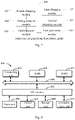
- Fig.1 is a method of generating a dependence graph provided by the present disclosure, as shown in Fig. 1 , the method includes the following steps.
- the function component may be a pre-written function component, and corresponding hook APIs used by one or more function components may be obtained.
- the hook API may include all hook APIs used by the function component. It should be appreciated that, the word “use” may also be understood as “call” herein.
- the hook API may include all hook APIs called by the function component. Further, the hook API may also be referred to as hook for short.
- the hook API may be a React hook API, which is configured to organize a component state in a React function component.
- the hook APIs may be classified on the basis of a holding state, cacheable and holding edge-effect.
- the hook APIs in the holding state include useState, useReducer, useRef, etc.
- the hook APIs that are cacheable may include useCallback, useMemo, etc.
- the hook APIs that are the holding edge-effect include useEffect, useLayoutEffect, etc.
- an abstract syntax tree of the function component is created, and then the hook API used by the function component is obtained in accordance with the syntax tree.
- the hook API used by the function component may also be directly extracted from the function component.
- a parameter value of the hook API used by the function component is obtained.
- the parameter value for each of the hook APIs obtained in S 102 may be obtained, and the parameter value includes at least one of an input parameter or a return value identifier.
- the parameter value for one of some of the hook APIs includes the input parameter and the return value identifier, while the parameter value for one of the other hook APIs may only include at least one of the input parameter or the return value identifier.
- some of the hook APIs each includes the input parameter only, but does not include the return value identifier, or some of the hook APIs each includes the return value identifier only, but does not include the input parameter.
- the dependence graph is generated.
- the hook API corresponds to a hook node in the dependence graph
- the parameter value corresponds to a value node in the dependence graph
- each of the hook APIs obtained in S102 corresponds to one hook node in the dependence graph. Specifically, a corresponding hook node is generated for each of the hook APIs.
- each of the parameter values obtained in S102 corresponds to one value node. For example, corresponding value nodes are generated for each of input parameters and each of identifiers of the return value.
- the sentence that there is the connection relationship between the value node and the corresponding hook node may refer to that, there are an edge connecting a value node corresponding to an input parameter to a hook node of a hook API corresponding to the input parameter, or there is an edge connecting a hook node of a hook API to a value node corresponding to a return value identifier for the hook API.
- the connection relationship between the value node and the hook node the dependence between the hook API and the input parameter, and/or, between the hook API and the return value identifier can be accurately represented.
- the hook API(s) constitutes the hook node(s) in the dependence graph
- the parameter value(s) of the hook API(s) constitutes the value node(s) in the dependence graph
- the relationship among the hook node(s) and the value node(s) can be presented through the dependence graph, which can help a developer to perform the code programming using the hook API(s) in a more convenient manner, thereby improving a guiding effect on the code programming, and thus, helping the developer to improve the code quality.
- the hook APIs used by the function component include three APIs, that is, useState, useCallback and useEffect, is taken for illustration.
- the return value identifier of useState may include count and setCount
- the input parameter of useCallback may include count
- the return value identifier of useCallback may include onLick
- the input parameter of useEffect may include setCount.
- the hook APIs obtained in S101 include useState, useCallback and useEffect, and a dependence graph as shown in Fig. 2 may be generated, where the numerals 201, 202 and 203 represent three hook APIs, i.e., useState, useCallback and useEffect, respectively, and the numerals 204, 205 and 206 represent three parameter values, i.e., count, setCount and onLick, respectively.
- the function component may include more hook APIs, as well as more complicated input parameters and return value identifiers.
- the method further includes:
- the customized hook API refers to a hook API defined by a developer on the basis of an atomic hook provided by React.
- the other hook API refer to one or more hook APIs between the customized hook API and the atomic hook API.
- the function component may include one or more customized hook APIs, and the above procedure may be performed with respect to each customized hook API.
- the parameter value may include at least one of the input parameter and the return value identifier.
- the parameter values for different hook APIs may be same or different.
- various hook APIs involved in the function component may be obtained, such that the dependence graph can present the dependence among the various hook APIs, thereby further improving the guiding effect of the dependence graph.
- the method further includes: in a case that the dependence graph includes a target value node of a new identifier capable of being obtained through an expression, generating a value node corresponding to the new identifier in the dependence graph, and establishing a connection relationship between the target value node and the value node of the new identifier.
- the target value node of the new identifier capable of being obtained through the expression refers to, a new identifier may be obtained in accordance with an identifier corresponding to a value node and the expression.
- the new identifier may be obtained by a certain input parameter identifier or a certain return value identifier using an expression, a value node corresponding to said input parameter or the return value identifier may be the target value node.
- the certain input parameter identifier or the certain return value identifier may serve as a variable for another identifier.
- the dependence graph is enabled to present the dependence among various value nodes, thereby further improving the guiding effect of the dependence graph.
- the method further includes:
- the XML expression may be a JSX expression.
- the obtaining the XML expression of the top level of the function component may include: obtaining the XML expression of the top level of the function component through the syntax tree of the function component.
- the generating the component node corresponding to the XML expression of the top level in the dependence graph may include: generating component nodes corresponding to all of or a part of XML expressions in relation to XML expressions of all top levels in the dependence graph, where each XML expression corresponds to one component node.
- the generating the component node corresponding to the XML expression of the top level in the dependence graph may include: generating a relationship graph among component nodes separately in the dependence graph, e.g., a relationship graph between a parent component node and a child component node, so as to create a forest map among the component nodes.
- the connection relationship between the target XML expression and the corresponding value node is created.
- a left diagram of Fig. 3 is the dependence graph generated in S103
- a right diagram of Fig. 3 is the created forest map
- each dotted line connecting the two diagrams represents a connection relationship between the target XML expression and the corresponding value node.
- the dependence among the value nodes for the XML expressions can be presented through the dependence graph, thereby further improving the guiding effect of the dependence graph.
- the generating the component node corresponding to the XML expression of the top level in the dependence graph includes: simplifying a syntax tree of the XML expression of the top level to obtain XML expression of the at least one predetermined level, and generating a component node corresponding to the XML expression of the at least one predetermined level in the dependence graph.
- the simplifying the syntax tree of the XML expression of the top level may include simplifying XML expressions in the syntax tree of the XML expression of the top levels and merely reserving the XML expression(s) of the at least one predetermined level as the component node(s).
- the at least one predetermined level includes a child level and/or a grandchild level, i.e., merely the XML expression of the child level and/or the XML expression of the grandchild level reserved as the component nodes.
- a hook node with an out-degree of 0 in the dependence graph may be definitely determined as a hook API or a component node having no return value.
- the quantity of connected subgraphs in the dependence graph is determined as the quantity of groups of sub-components whose states are coupled to each other during the operation.
- the developer may add a common parent component for components corresponding to the two component nodes, and behaviors of the two child-components are packaged into one component, so as to differentiate them from a component in the other connected subgraph.
- the developer may decouple two child-components corresponding to the two component nodes from each other by splitting in accordance with the state, so as to prevent the adverse impact on the component reusability in future.
- the developer may optimize the component caching actions including but not limited to React.memo, so as to achieve more performance gain.
- the developer may pay attention to whether the hook API(s) in the holding state in that path can be further split in accordance with the state, thereby attempting to add a cacheable path.
- a developer who newly participates in a project may rapidly understand the state of the component through the dependence graph, which enable the developer to be familiar with a complicated project rapidly and efficiently.
- a common mode(s) and a common path(s) in these dependence graphs may be found through data analysis, and as a result, a code abstraction can be performed on the common mode, thereby improving the code reusability.
- Fig. 4 is an apparatus 400 for generating a dependence graph provided by the present disclosure.
- the apparatus 400 for generating the dependence graph includes:
- the apparatus further includes:
- the apparatus further includes: a second generation module 406, configured to, in a case that the dependence graph includes a target value node of a new identifier capable of being obtained through an expression, generate a value node corresponding to the new identifier in the dependence graph, and establish a connection relationship between the target value node and the value node of the new identifier.
- a second generation module 406 configured to, in a case that the dependence graph includes a target value node of a new identifier capable of being obtained through an expression, generate a value node corresponding to the new identifier in the dependence graph, and establish a connection relationship between the target value node and the value node of the new identifier.
- the apparatus further includes:
- the present disclosure further provides, in embodiments of the present disclosure, an electronic device, a computer-readable storage medium and a computer program product.
- Fig. 8 is a schematic block diagram of an exemplary electronic device 800 for implementing embodiments of the present disclosure.
- the electronic device is intended to represent all kinds of digital computers, such as a laptop computer, a desktop computer, a work station, a personal digital assistant, a server, a blade server, a main frame or other suitable computers.
- the electronic device may also represent all kinds of mobile devices, such as a personal digital assistant, a cell phone, a smart phone, a wearable device and other similar computing devices.
- the components shown herein, their connections and relationships, and their functions, are meant to be exemplary only, and are not meant to limit implementations of the present disclosure described and/or claimed herein.
- the electronic device 800 includes a computing unit 801 configured to execute various actions and processes in accordance with a computer program stored in a read only memory (ROM) 802, or a computer program loaded into a random access memory (RAM) 803 from a storage unit 808.
- Various programs and data desired for the operation of the electronic device 800 may also be stored in the RAM 803.
- the computing unit 801, the ROM 802 and the RAM 803 may be connected to each other via a bus 804.
- an input/output (I/O) interface 805 may also be connected to the bus 804.
- the multiple components include: an input unit 808, e.g., a keyboard, a mouse and the like; an output unit 808, e.g., various types of displayers, loudspeakers, and the like; a storage unit 808, e.g., a magnetic disk, an optic disk and the like; and a communications unit 809, e.g., a network card, a modem, a wireless communications transceiver, and the like.
- the communications unit 809 allows the electronic device 800 to exchange information/data with other devices through a computer network such as Internet and/or other telecommunications networks.
- the computing unit 801 may be any general purpose and/or dedicated processing components having a processing and computing capability. Some examples of the computing unit 801 include, but are not limited to: a central processing unit (CPU), a graphic processing unit (GPU), various dedicated artificial intelligence (AI) computing chips, various computing units running a machine learning model algorithm, a digital signal processor (DSP), and any suitable processor, controller, microcontroller, etc.
- the computing unit 801 carries out the aforementioned methods and processes, e.g., the method of generating the dependence graph.
- the method of generating the dependence graph may be implemented as a computer software program tangibly embodied in a machine readable medium such as the storage unit 808.
- all or a part of the computer program may be loaded and/or installed into the electronic device 800 through the ROM 802 and/or the communications unit 809.
- the computer program When the computer program is loaded into the RAM 803 and executed by the computing unit 801, one or more steps of the foregoing method of generating the dependence graph may be implemented.
- the computing unit 801 may be configured to implement the method of generating the dependence graph in any other suitable manner (e.g., by means of a firmware).
- Various implementations of the aforementioned systems and techniques may be implemented in a digital electronic circuit system, an integrated circuit system, a field-programmable gate array (FPGA), an application specific integrated circuit (ASIC), an application specific standard product (ASSP), a system on chip (SOC), a complex programmable logic device (CPLD), computer hardware, firmware, software, and/or a combination thereof.
- the various implementations may include an implementation using one or more computer programs.
- the one or more computer programs may be executed and/or interpreted on a programmable system including at least one programmable processor.
- the programmable processor may be a dedicated or general purpose programmable processor, which may receive data and instructions from a storage system, at least one input device and at least one output device, and may transmit data and instructions to the storage system, the at least one input device and the at least one output device.
- Program codes for implementing the methods of the present disclosure may be written by any combination of one or more programming languages. These program codes may be provided to a processor or controller of a general purpose computer, a special purpose computer, or other programmable data processing device, such that the program codes, when being executed by the processor or controller, cause the functions/operations specified in the flow chart and/or block diagram to be implemented.
- the program codes may be executed entirely on a machine, partially on the machine, partially on the machine and partially on a remote machine as a standalone software package, or entirely on the remote machine or server.
- the machine readable medium may be a tangible medium, and may include or store a program used by an instruction executing system, device or apparatus, or a program used in conjunction with the instruction executing system, device or apparatus.
- the machine readable medium may be a machine readable signal medium or a machine readable storage medium.
- the machine readable medium includes, but is not limited to: an electronic, magnetic, optical, electromagnetic, infrared, or semiconductor system, device or apparatus, or any suitable combination thereof.
- a more specific example of the machine readable storage medium includes: an electrical connection based on one or more wires, a portable computer disk, a hard disk, a random access memory (RAM), a read only memory (ROM), an erasable programmable read only memory (EPROM or flash memory), an optic fiber, a portable compact disc read only memory (CD-ROM), an optical storage device, a magnetic storage device, or any suitable combination thereof.
- the system and technique described herein may be implemented on a computer.
- the computer is provided with a display device (for example, a cathode ray tube (CRT) or liquid crystal display (LCD) monitor) for displaying information to the user, a keyboard and a pointing device (for example, a mouse or a track ball).
- a display device for example, a cathode ray tube (CRT) or liquid crystal display (LCD) monitor
- a keyboard and a pointing device for example, a mouse or a track ball.
- the user may provide an input to the computer through the keyboard and the pointing device.
- Other kinds of devices may be provided for the interaction with the user, for example, a feedback provided to the user may be any manner of sensory feedback (e.g., visual feedback, auditory feedback, or tactile feedback); and the input from the user may be received by any means (including sound input, voice input, or tactile input).
- the system and technique described herein may be implemented in a computing system that includes a back-end component (e.g., as a data server), or that includes a middleware component (e.g., an application server), or that includes a front-end component (e.g., a client computer having a graphical user interface or a Web browser through which a user can interact with an implementation of the system and technique described hereby), or any combination of such back-end, middleware, or front-end components.
- the components of the system can be interconnected by any form or medium of digital data communications (e.g., a communications network). Examples of communications networks include a local area network (LAN), a wide area network (WAN) and the Internet.
- LAN local area network
- WAN wide area network
- the Internet the global information network
- the computer system can include a client and a server.
- the client and server are generally remote from each other and generally interact through the communications network.
- the relationship of client and server arises by virtue of computer programs running on respective computers and having a client-server relationship to each other. It should be appreciated that, all forms of processes shown above may be used, and steps thereof may be reordered, added or deleted. For example, steps set forth in the present disclosure may be performed in parallel, performed sequentially, or performed in a different order, as long as the expected result of the technical solution of the present disclosure can be achieved, and there is no limitation in this regard.
Landscapes
- Engineering & Computer Science (AREA)
- Theoretical Computer Science (AREA)
- Software Systems (AREA)
- General Engineering & Computer Science (AREA)
- Physics & Mathematics (AREA)
- General Physics & Mathematics (AREA)
- Stored Programmes (AREA)
- Image Generation (AREA)
Applications Claiming Priority (2)
| Application Number | Priority Date | Filing Date | Title |
|---|---|---|---|
| CN202110219222.2A CN112925522B (zh) | 2021-02-26 | 2021-02-26 | 依赖图生成方法、装置、设备、存储介质和程序产品 |
| PCT/CN2021/115006 WO2022179070A1 (zh) | 2021-02-26 | 2021-08-27 | 依赖图生成方法、装置、设备、存储介质和程序产品 |
Publications (2)
| Publication Number | Publication Date |
|---|---|
| EP4075263A1 true EP4075263A1 (de) | 2022-10-19 |
| EP4075263A4 EP4075263A4 (de) | 2023-06-21 |
Family
ID=76172325
Family Applications (1)
| Application Number | Title | Priority Date | Filing Date |
|---|---|---|---|
| EP21893117.8A Withdrawn EP4075263A4 (de) | 2021-02-26 | 2021-08-27 | Verfahren und gerät zum erzeugen von abhängigkeitsgraphen, vorrichtung, speichermedium und programmprodukt |
Country Status (6)
| Country | Link |
|---|---|
| US (1) | US12056492B2 (de) |
| EP (1) | EP4075263A4 (de) |
| JP (1) | JP7389246B2 (de) |
| KR (1) | KR102710506B1 (de) |
| CN (1) | CN112925522B (de) |
| WO (1) | WO2022179070A1 (de) |
Families Citing this family (7)
| Publication number | Priority date | Publication date | Assignee | Title |
|---|---|---|---|---|
| CN112925522B (zh) * | 2021-02-26 | 2023-11-21 | 北京百度网讯科技有限公司 | 依赖图生成方法、装置、设备、存储介质和程序产品 |
| CN114115901B (zh) * | 2021-11-26 | 2025-05-02 | 北京百度网讯科技有限公司 | 一种数据处理方法、装置、电子设备及存储介质 |
| CN114416030B (zh) * | 2021-12-24 | 2025-04-25 | 北京百度网讯科技有限公司 | 数据处理方法、装置、设备、存储介质及程序产品 |
| CN114697398B (zh) * | 2022-03-23 | 2023-10-17 | 北京百度网讯科技有限公司 | 数据处理方法、装置、电子设备、存储介质及产品 |
| KR102653900B1 (ko) * | 2023-08-04 | 2024-04-03 | 쿠팡 주식회사 | 전자 장치 및 그의 정보 제공 방법 |
| CN119473236A (zh) * | 2025-01-10 | 2025-02-18 | 山东大学 | 程序合成方法、装置、设备以及存储介质 |
| CN120631376B (zh) * | 2025-08-08 | 2025-11-14 | 恒生电子股份有限公司 | 一种软件模块编译方法、电子设备、介质及产品 |
Family Cites Families (11)
| Publication number | Priority date | Publication date | Assignee | Title |
|---|---|---|---|---|
| US5689711A (en) * | 1995-04-21 | 1997-11-18 | Bardasz; Theodore | Method and apparatus for representing data dependencies in software modeling systems |
| CN102054149B (zh) * | 2009-11-06 | 2013-02-13 | 中国科学院研究生院 | 一种恶意代码行为特征提取方法 |
| US9047325B2 (en) * | 2013-04-08 | 2015-06-02 | International Business Machines Corporation | Modularizing complex XML data for generation and extraction |
| US10387558B2 (en) * | 2016-02-23 | 2019-08-20 | International Business Machines Corporation | Provision of a separate input interface for user interaction with a spreadsheet |
| CN108037913B (zh) | 2017-12-21 | 2021-08-17 | 西安邮电大学 | xUML4MC模型到MSVL语言程序的转换方法、计算机可读存储介质 |
| US11379292B2 (en) * | 2019-06-27 | 2022-07-05 | Capital One Services, Llc | Baseline modeling for application dependency discovery, reporting, and management tool |
| US11422917B2 (en) * | 2019-07-26 | 2022-08-23 | Red Hat, Inc. | Deriving software application dependency trees for white-box testing |
| CN111045678A (zh) | 2019-11-06 | 2020-04-21 | 北京奇艺世纪科技有限公司 | 页面执行动态代码的方法、装置、设备及存储介质 |
| CN110928550B (zh) | 2019-11-19 | 2023-11-24 | 上海工程技术大学 | 基于关键词Trie树消除GCC抽象语法树冗余的方法 |
| CN114637891A (zh) * | 2020-12-15 | 2022-06-17 | 来未来科技(浙江)有限公司 | 一种业务流程装配渲染及其可视化运维的方法 |
| CN112925522B (zh) | 2021-02-26 | 2023-11-21 | 北京百度网讯科技有限公司 | 依赖图生成方法、装置、设备、存储介质和程序产品 |
-
2021
- 2021-02-26 CN CN202110219222.2A patent/CN112925522B/zh active Active
- 2021-08-27 EP EP21893117.8A patent/EP4075263A4/de not_active Withdrawn
- 2021-08-27 WO PCT/CN2021/115006 patent/WO2022179070A1/zh not_active Ceased
- 2021-08-27 US US17/780,940 patent/US12056492B2/en active Active
- 2021-08-27 JP JP2022520829A patent/JP7389246B2/ja active Active
- 2021-08-27 KR KR1020227029703A patent/KR102710506B1/ko active Active
Also Published As
| Publication number | Publication date |
|---|---|
| US12056492B2 (en) | 2024-08-06 |
| CN112925522B (zh) | 2023-11-21 |
| CN112925522A (zh) | 2021-06-08 |
| EP4075263A4 (de) | 2023-06-21 |
| KR102710506B1 (ko) | 2024-09-27 |
| US20240053991A1 (en) | 2024-02-15 |
| JP2023528102A (ja) | 2023-07-04 |
| KR20220125720A (ko) | 2022-09-14 |
| JP7389246B2 (ja) | 2023-11-29 |
| WO2022179070A1 (zh) | 2022-09-01 |
Similar Documents
| Publication | Publication Date | Title |
|---|---|---|
| US12056492B2 (en) | Method and apparatus for generating dependence graph, device, storage medium and program product | |
| CN106648945B (zh) | 一种接口数据测试方法、装置及电子设备 | |
| CN113220367B (zh) | 小程序的运行方法、装置、电子设备及存储介质 | |
| CN114398023B (zh) | 生成文件的方法、配置页面的方法和装置 | |
| US20250123812A1 (en) | Code completion method based on big model, apparatus and electronic device | |
| WO2023221416A1 (zh) | 信息生成方法、装置、设备以及存储介质 | |
| CN112860356A (zh) | 一种api调用控制方法、装置、电子设备和存储介质 | |
| CN118363977A (zh) | 结构化查询语言语句生成方法、装置、设备及存储介质 | |
| CN117992569B (zh) | 基于生成式大模型生成文档的方法、装置、设备及介质 | |
| CN113642295B (zh) | 页面排版方法、装置及计算机程序产品 | |
| CN105302556A (zh) | 实现计算的方法和系统以及服务器装置 | |
| CN117407468A (zh) | 生成式内容的显示方法、装置、电子设备及存储介质 | |
| CN119848045A (zh) | 基于大模型的数据血缘解析方法、装置、设备和介质 | |
| CN114168119B (zh) | 代码文件编辑方法、装置、电子设备以及存储介质 | |
| CN117610580A (zh) | 基于大模型的指令识别方法、装置、电子设备及存储介质 | |
| CN117785165A (zh) | 基于大模型的图表生成方法、装置及电子设备 | |
| CN116341663A (zh) | 深度学习推理框架的扩展方法、装置、设备及介质 | |
| CN115794742A (zh) | 文件路径数据处理方法、装置、设备及存储介质 | |
| CN117270838B (zh) | 一种通用公式脚本的生成方法、装置、设备及介质 | |
| CN117093691B (zh) | 基于大语言模型的系统帮助方法、装置、设备及存储介质 | |
| CN115237420A (zh) | 代码生成方法、装置、电子设备及计算机可读存储介质 | |
| CN119149146A (zh) | 基于大模型的接口调用方法、装置及电子设备 | |
| CN121785601A (zh) | 宏功能实现方法、系统及存储介质 | |
| CN117555588A (zh) | 接口文档生成方法、装置、电子设备及存储介质 | |
| CN115480744A (zh) | 命令执行日志的输出方法及装置、电子设备和存储介质 |
Legal Events
| Date | Code | Title | Description |
|---|---|---|---|
| STAA | Information on the status of an ep patent application or granted ep patent |
Free format text: STATUS: UNKNOWN |
|
| STAA | Information on the status of an ep patent application or granted ep patent |
Free format text: STATUS: THE INTERNATIONAL PUBLICATION HAS BEEN MADE |
|
| PUAI | Public reference made under article 153(3) epc to a published international application that has entered the european phase |
Free format text: ORIGINAL CODE: 0009012 |
|
| STAA | Information on the status of an ep patent application or granted ep patent |
Free format text: STATUS: REQUEST FOR EXAMINATION WAS MADE |
|
| 17P | Request for examination filed |
Effective date: 20220526 |
|
| AK | Designated contracting states |
Kind code of ref document: A1 Designated state(s): AL AT BE BG CH CY CZ DE DK EE ES FI FR GB GR HR HU IE IS IT LI LT LU LV MC MK MT NL NO PL PT RO RS SE SI SK SM TR |
|
| A4 | Supplementary search report drawn up and despatched |
Effective date: 20230524 |
|
| RIC1 | Information provided on ipc code assigned before grant |
Ipc: G06F 9/448 20180101ALI20230517BHEP Ipc: G06F 8/41 20180101AFI20230517BHEP |
|
| STAA | Information on the status of an ep patent application or granted ep patent |
Free format text: STATUS: THE APPLICATION IS DEEMED TO BE WITHDRAWN |
|
| 18D | Application deemed to be withdrawn |
Effective date: 20240103 |