EP4075124A1 - Adjustment and positioning device and method for ray source assembly, and radiation scan imaging apparatus - Google Patents
Adjustment and positioning device and method for ray source assembly, and radiation scan imaging apparatus Download PDFInfo
- Publication number
- EP4075124A1 EP4075124A1 EP20899524.1A EP20899524A EP4075124A1 EP 4075124 A1 EP4075124 A1 EP 4075124A1 EP 20899524 A EP20899524 A EP 20899524A EP 4075124 A1 EP4075124 A1 EP 4075124A1
- Authority
- EP
- European Patent Office
- Prior art keywords
- component
- ray source
- source assembly
- hole
- adjusting
- Prior art date
- Legal status (The legal status is an assumption and is not a legal conclusion. Google has not performed a legal analysis and makes no representation as to the accuracy of the status listed.)
- Granted
Links
Images


Classifications
-
- G—PHYSICS
- G01—MEASURING; TESTING
- G01N—INVESTIGATING OR ANALYSING MATERIALS BY DETERMINING THEIR CHEMICAL OR PHYSICAL PROPERTIES
- G01N23/00—Investigating or analysing materials by the use of wave or particle radiation, e.g. X-rays or neutrons, not covered by groups G01N3/00 – G01N17/00, G01N21/00 or G01N22/00
- G01N23/02—Investigating or analysing materials by the use of wave or particle radiation, e.g. X-rays or neutrons, not covered by groups G01N3/00 – G01N17/00, G01N21/00 or G01N22/00 by transmitting the radiation through the material
- G01N23/04—Investigating or analysing materials by the use of wave or particle radiation, e.g. X-rays or neutrons, not covered by groups G01N3/00 – G01N17/00, G01N21/00 or G01N22/00 by transmitting the radiation through the material and forming images of the material
- G01N23/046—Investigating or analysing materials by the use of wave or particle radiation, e.g. X-rays or neutrons, not covered by groups G01N3/00 – G01N17/00, G01N21/00 or G01N22/00 by transmitting the radiation through the material and forming images of the material using tomography, e.g. computed tomography [CT]
-
- G—PHYSICS
- G01—MEASURING; TESTING
- G01N—INVESTIGATING OR ANALYSING MATERIALS BY DETERMINING THEIR CHEMICAL OR PHYSICAL PROPERTIES
- G01N23/00—Investigating or analysing materials by the use of wave or particle radiation, e.g. X-rays or neutrons, not covered by groups G01N3/00 – G01N17/00, G01N21/00 or G01N22/00
- G01N23/02—Investigating or analysing materials by the use of wave or particle radiation, e.g. X-rays or neutrons, not covered by groups G01N3/00 – G01N17/00, G01N21/00 or G01N22/00 by transmitting the radiation through the material
- G01N23/04—Investigating or analysing materials by the use of wave or particle radiation, e.g. X-rays or neutrons, not covered by groups G01N3/00 – G01N17/00, G01N21/00 or G01N22/00 by transmitting the radiation through the material and forming images of the material
-
- G—PHYSICS
- G01—MEASURING; TESTING
- G01T—MEASUREMENT OF NUCLEAR OR X-RADIATION
- G01T1/00—Measuring X-radiation, gamma radiation, corpuscular radiation, or cosmic radiation
- G01T1/29—Measurement performed on radiation beams, e.g. position or section of the beam; Measurement of spatial distribution of radiation
- G01T1/2914—Measurement of spatial distribution of radiation
- G01T1/2985—In depth localisation, e.g. using positron emitters; Tomographic imaging (longitudinal and transverse section imaging; apparatus for radiation diagnosis sequentially in different planes, steroscopic radiation diagnosis)
-
- G—PHYSICS
- G01—MEASURING; TESTING
- G01V—GEOPHYSICS; GRAVITATIONAL MEASUREMENTS; DETECTING MASSES OR OBJECTS; TAGS
- G01V5/00—Prospecting or detecting by the use of ionising radiation, e.g. of natural or induced radioactivity
-
- G—PHYSICS
- G01—MEASURING; TESTING
- G01V—GEOPHYSICS; GRAVITATIONAL MEASUREMENTS; DETECTING MASSES OR OBJECTS; TAGS
- G01V5/00—Prospecting or detecting by the use of ionising radiation, e.g. of natural or induced radioactivity
- G01V5/20—Detecting prohibited goods, e.g. weapons, explosives, hazardous substances, contraband or smuggled objects
- G01V5/22—Active interrogation, i.e. by irradiating objects or goods using external radiation sources, e.g. using gamma rays or cosmic rays
- G01V5/226—Active interrogation, i.e. by irradiating objects or goods using external radiation sources, e.g. using gamma rays or cosmic rays using tomography
-
- G—PHYSICS
- G01—MEASURING; TESTING
- G01N—INVESTIGATING OR ANALYSING MATERIALS BY DETERMINING THEIR CHEMICAL OR PHYSICAL PROPERTIES
- G01N2223/00—Investigating materials by wave or particle radiation
- G01N2223/30—Accessories, mechanical or electrical features
- G01N2223/308—Accessories, mechanical or electrical features support of radiation source
-
- G—PHYSICS
- G01—MEASURING; TESTING
- G01N—INVESTIGATING OR ANALYSING MATERIALS BY DETERMINING THEIR CHEMICAL OR PHYSICAL PROPERTIES
- G01N2223/00—Investigating materials by wave or particle radiation
- G01N2223/30—Accessories, mechanical or electrical features
- G01N2223/321—Accessories, mechanical or electrical features manipulator for positioning a part
-
- G—PHYSICS
- G01—MEASURING; TESTING
- G01N—INVESTIGATING OR ANALYSING MATERIALS BY DETERMINING THEIR CHEMICAL OR PHYSICAL PROPERTIES
- G01N2223/00—Investigating materials by wave or particle radiation
- G01N2223/30—Accessories, mechanical or electrical features
- G01N2223/33—Accessories, mechanical or electrical features scanning, i.e. relative motion for measurement of successive object-parts
- G01N2223/3303—Accessories, mechanical or electrical features scanning, i.e. relative motion for measurement of successive object-parts object fixed; source and detector move
-
- G—PHYSICS
- G01—MEASURING; TESTING
- G01N—INVESTIGATING OR ANALYSING MATERIALS BY DETERMINING THEIR CHEMICAL OR PHYSICAL PROPERTIES
- G01N2223/00—Investigating materials by wave or particle radiation
- G01N2223/40—Imaging
Definitions
- Embodiments of the present disclosure generally relates to a field of radiation detection, and in particular, to a device and a method for adjusting and positioning capable of realizing a translation and a rotation of a ray source assembly, and a radiation scan imaging apparatus including the device for adjusting and positioning.
- a radiation ray such as an X-ray has a wide range of application in fields of industrial non-destructive detection, safety inspection, medical diagnosis and treatment, etc., for example, CT imaging and security inspection, in which a radiation ray emitted by a ray source assembly scans an object or a human body to be inspected in a scan channel.
- CT imaging and security inspection in which a radiation ray emitted by a ray source assembly scans an object or a human body to be inspected in a scan channel.
- the device for fixing the ray source assembly is complicated in structure, the device is not easily adjusted, and is poor in adjustment accuracy, which affects the imaging quality.
- the present disclosure is provided in order to overcome at least one of the above and other problems and defects in the prior art.
- a device for adjusting and positioning which is configured to adjust an orientation of a ray source assembly of a radiation scan imaging apparatus, wherein the radiation scan imaging apparatus has an apparatus frame, and the device for adjusting and positioning comprises:
- a base comprising a first component and a second component connected to each other, and is configured to support the ray source assembly, such that the ray source assembly is vertically positioned on the second component;
- the base comprises an upper plate as the second component and a lower plate as the first component, the upper plate and the lower plate are stacked on each other in a vertical direction, such that the ray source assembly is positioned on an upper surface of the upper plate, and the upper plate and the lower plate are connected together in a manner that they are movable relative to each other.
- an upright shaft is provided on an upper surface of the lower plate facing the upper plate, a through hole is provided at a position of the upper plate corresponding to the shaft, the shaft passes through the through hole and extends upwardly so as to engage with a corresponding shaft hole of the ray source assembly, such that the ray source assembly and the upper plate are capable of rotating around the shaft under a driving of the second adjustment mechanism.
- the shaft is positioned such that an axis of the shaft substantially coincides with a vertical axis of the ray source assembly.
- a positioning pin is provided on an upper surface of the upper plate facing away from the lower plate, the positioning is being engaged with a corresponding pin hole of the ray source assembly, so as to position the ray source assembly by preventing the ray source assembly from moving relative to the upper plate in a plane perpendicular to the vertical direction.
- the first adjustment mechanism comprises: a first holder configured to be fixed to the apparatus frame; and a first adjustment bolt threadedly engaged with the first holder and connected to the first component, such that a rotation of the first adjustment bolt relative to the first holder drives the first component to translate, so as to drive the second component connected with the first component and the ray source assembly positioned on the second component to translate relative to the apparatus frame along the first direction.
- an elongated first hole is provided on the first component, the elongated first hole penetrates the first component and extends in the first direction; and the device for adjusting and positioning further comprises a first fastener inserted into the first hole and tightened so as to mount the first component to the apparatus frame, and the first fastener is configured to be releasable during a translation movement so as to allow the first component to translate relative to the apparatus frame in a manner that an inner wall of the first hole abuts against the first fastener.
- the device for adjusting and positioning further comprises a translation guide member configured to be fixed to the apparatus frame and configured to guide the base to translate.
- the second adjustment mechanism comprises: a second holder configured to be fixed to the apparatus frame; and a second adjustment bolt threadedly engaged with the second holder and connected to the second component, such that a rotation of the second adjustment bolt relative to the second holder drives the second component to rotate, so as to drive the ray source assembly positioned on the second component to rotate.
- the second adjustment bolt is arranged such that a rotation of the second adjustment bolt relative to the second seat applies to the second component a force tangent to a circumferential direction of the rotation of the second component.
- a second hole is provided on the first component; an elongated third hole is provided on the second component, the elongated third hole penetrates the second component and extends in a direction at an angle to the first direction; the device for adjusting and positioning further comprises a second fastener inserted into and passing through the third hole and engaged with the second hole so as to fasten the second component to the first component, and configured to be releasable during the rotation so as to allow the second component to rotate in a manner that an inner wall of the third hole abuts against the second fastener.
- the elongated third hole extends in a direction tangent to as circumferential direction of the rotation of the second component.
- the first adjustment mechanism further comprises: a third holder fixed to the first component and connected with the first adjustment bolt.
- the second adjustment mechanism further comprises: a fourth holder (330) fixed to the second component and connected with the second adjustment bolt.
- a radiation scan imaging apparatus including a ray source assembly and the device for adjusting and positioning according to any embodiment of the present disclosure, wherein the ray source assembly is supported on the device for adjusting and positioning, such that an orientation of the ray source assembly is adjusted by the device for adjusting and positioning.
- a method for adjusting an orientation of a ray source assembly of a radiation scan imaging apparatus by using the device for adjusting and positioning including at least one of the following steps:
- the translation adjustment step comprises: driving the upper plate and the lower plate to move together relative to the apparatus frame through the first adjustment mechanism, so as to drive the ray source assembly to translate in the first direction; and the rotation adjustment step comprises: driving the upper plate to rotate relative to the lower plate through the second adjustment mechanism, so as to drive the ray source assembly to rotate.
- the rotation adjustment step further comprises: driving the upper plate and the ray source assembly to rotate about the shaft through the second adjustment mechanism.
- the translation adjustment step comprises: rotating the first adjustment bolt relative to the first holder to drive the first component to translate, so as to drive the second component connected with the first component and the ray source assembly positioned on the second component to translate relative to the apparatus frame along the first direction.
- the translation adjustment step further comprises: releasing the first fastener and driving the first component to translate relative to the apparatus frame through the first adjustment mechanism in a manner that an inner wall of the first hole abuts against the first fastener.
- the rotation adjustment step comprises: rotating the second adjustment bolt relative to the second holder to drive the second component to rotate, so as to drive the ray source assembly positioned on the second component to rotate.
- the rotation adjustment step comprises: applying a force to the second component in a direction tangent to a circumferential direction of a rotation of the second component through a rotation of the second adjustment bolt relative to the second holder.
- the rotation adjustment step comprises: releasing the second fastener to allow the second component to rotate under a driving of the second adjustment mechanism in a manner that an inner wall of the third hole abuts against the second fastener.
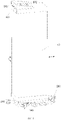
- FIG. 1 schematically shows a radiation scan imaging apparatus according to an exemplary embodiment of the present disclosure.
- the exemplary radiation scan imaging apparatus may be a component of a security inspection system, such as a CT imaging apparatus.
- the radiation scan imaging apparatus includes a radiation device for generating a radiation scan beam, such as a ray source assembly 10 for generating a ray beam, which may include a ray source or a radiation source such as an X-ray machine, an isotope ray source, etc.
- the ray source assembly 10 has a cylindrical profile, such as a substantial cuboid.
- the present disclosure is not limited to this, and it may also take any suitable form such as a cylinder as actually required.
- the radiation scan imaging apparatus further includes an adjusting and positioning device configured to adjust an orientation of the ray source assembly 10 so as to adjust a target point position of a ray source and improve an imaging quality.
- the adjusting and positioning device includes a base 100 for supporting the ray source assembly 10, such that the ray source assembly 10 is substantially vertically positioned and held on the base 100.
- the base 100 includes a first component and a second component.
- the first component and the second component are connected to each other in a manner that they are movable relative to each other, for example, the second component may, for example, rotate relative to the first component, or the first component and the second component may move together or integrally in a translational direction (also referred to as a first direction).
- the ray source assembly is substantially vertically positioned on the second component.
- the adjusting and positioning device further includes an adjustment mechanism configured to drive the base to drive, thereby driving the ray source assembly supported and held on the base to perform an appropriate movement, such as rotation and translation, so as to adjust an orientation of the ray source assembly, such that a target point position of the ray source may be adjusted.
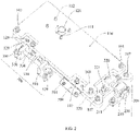
- the adjusting and positioning device includes a first adjustment mechanism 200 and a second adjustment mechanism 300, which are respectively configured to drive the base and thereby driving the ray source assembly to perform a movement of different forms, such as rotation, translation, etc.
- the adjusting and positioning device provided in the present disclosure may implement an independent adjustment of the translation and the rotation of the ray source assembly.
- the first adjustment mechanism 200 drives the ray source assembly 10 to perform a translational movement in the first direction (as shown by a bidirectional dashed straight arrow in FIG. 1 ) by driving an entire base or a part of the base to move relative to an apparatus frame, so as to adjust a position of the ray source assembly.
- the first adjustment mechanism may be mounted to the first component of the base and to the apparatus frame (not shown) of the radiation scan imaging apparatus.
- the first adjustment mechanism drives the first component to move, so as to drive the base or other parts of the base (e.g., the second component connected with the first component) to move, thereby driving the ray source assembly positioned on the base to perform a translation relative to the apparatus frame.
- the second adjustment mechanism 300 is configured to drive the base 100 or a part of the base to move so as to drive the ray source assembly 10 to rotate (as shown by the bidirectional dashed arc arrow in FIG. 1 ) to adjust a beam emitting direction of the ray source assembly 10.
- a rotation angle range of the ray source assembly may be set as actually required.
- an adjustment of the rotation of the ray source assembly is a fine adjustment whose rotation angle is small, with a range of ⁇ 5°, ⁇ 3°, and ⁇ 1°, for example.
- the second adjustment mechanism may be mounted to the second component of the base and the apparatus frame, and may drive the ray source assembly to rotate by driving the second component to move (for example, rotate relative to the first component).
- the adjusting and positioning device may further include a top bracket 400, as shown in FIG. 1 .
- the top bracket 400 is mounted to the apparatus frame and may be connected to the ray source assembly 10, such as a top or a side of the ray source assembly 10.
- the top bracket 400 is movably (e.g., horizontally translatable) mounted to the apparatus frame through a pin shaft 401, and the top bracket 400 is connected to the ray source assembly 10 in a manner that the ray source assembly 10 is allowed to move (e.g., rotate).
- a connection is realized by means of, for example, a cooperation of a shaft 402 with a corresponding hole.
- the top bracket cooperates with the base to hold the ray source assembly therebetween to prevent a vertical movement of the ray source assembly, but allow a movement (e.g., a rotation, a horizontal translation) of the ray source assembly relative to the apparatus frame.
- the base may take various forms or structures to cooperate with the adjustment mechanism. Based on a drive of the adjustment mechanism, the ray source assembly supported on it is driven to move, so as to realize an adjustment of the target point position of the ray source, ensure the accuracy of the target point position, and improve the imaging quality.
- the base 100 includes a first component and a second component in a form of a generally flat plate, respectively, and the first component and the second component are separate pieces. Referring to FIG. 1-FIG.
- the base 100 includes an upper plate 110 as the second component and a lower plate 120 as the first component, and the upper plate 110 and the lower plate 120 are stacked on each other in the vertical direction and connected to each other in a manner that they are moveable (e.g., rotatable) relative to each other. Additionally, as described below, the upper plate 110 and the lower plate 120 may also be moved together or integrally in a translation direction, for example, the lower plate drives the upper plate to translate together.
- the ray source assembly 10 is positioned on an upper surface of the upper plate 110.
- a shaft 121 is provided on an upper surface of the lower plate 120 facing the upper plate 110, which is, for example, upright.
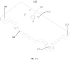
- a through hole 111 is provided at a position of the upper plate 110 corresponding to the shaft 121, and the shaft 121 passes through the through hole 111 and extends upward to engage with a corresponding shaft hole of the ray source assembly 10 (e.g., a shaft hole located at a bottom of the ray source assembly), such that the upper plate 110 and the ray source assembly 10 positioned thereon may rotate around the shaft 121 under a driving of the adjustment mechanism 300 to realize the rotation adjustment.
- the shaft 121 is positioned such that an axis of the shaft substantially coincides with a vertical axis of the ray source assembly 10, thereby a smoother rotation may be realized.
- a positioning pin 112 is provided on the upper surface of the upper plate 110 facing away from the lower plate 120, and the positioning pin 112 is engaged with a corresponding pin hole of the ray source assembly 10 (e.g., a pin hole at the bottom of the ray source assembly), such that the ray source assembly 10 is positioned relative to the upper plate 110, so as to prevent the ray source assembly 10 from moving relative to the upper plate 110 in a plane perpendicular to the vertical direction, thereby a movement of the upper plate 110 may drive the ray source assembly 10 to move together.
- a plurality of positioning pins 112 may be provided around the shaft 121.
- the plurality of positioning pins 112 may be irregularly arranged to ensure that the ray source assembly 10 is not wrongly oriented. It may be understood that a positioning manner of the ray source assembly relative to the base is not limited to this, and any suitable detachable or non-detachable fixing or positioning manner, such as a clamp, etc., may also be adopted as required.
- a first hole 127 is provided on the lower plate 120, and the first hole 127 penetrates the lower plate 120 in a thickness direction (e.g., a vertical direction) of the lower plate.
- the first hole 127 is, for example, an elongated hole extending substantially along the translation direction.
- the adjusting and positioning device further includes a first fastener 107, and the first fastener is inserted into the first hole 121 and screwed to the apparatus frame, so as to mount the lower plate 120 to the apparatus frame.
- the lower plate is detachably fixed to the apparatus frame.
- the first fastener 107 may be tightened to press the lower plate against the apparatus frame.
- the first fastener 107 may be released during the translational movement described above, but is still fixed to the apparatus frame and inserted into the first hole 127, so as to allow the lower plate 120 to translate relative to the apparatus frame with an inner wall of the first hole 127 abutting the first fastener 107.
- the first fastener translates relative to the apparatus frame and remains fixed relative to the apparatus frame, and a cooperation of the first fastener with the elongated first hole may guide the lower plate to translate relative to the apparatus frame.
- the first fastener is tightened again, so as to fixedly press the lower plate against the apparatus frame or fixedly position the lower plate relative to the apparatus frame, thereby avoiding a necessary movement of the ray source assembly during operation.
- an additional elongated hole 128 may also be provided on the lower plate 120, the additional elongated hole 128 extends along the above translation direction, and a positioning member 129 partially positioned in the elongated hole 128 is fixed to the apparatus frame, such that a cooperation of the elongated hole 128 with the positioning member 129 may also guide such a translation movement, and it may also ensure a correct positioning or mounting of the lower plate.
- the upper plate 110 and the lower plate 120 are configured or arranged such that the first fastener 107 is exposed, so as to facilitate mounting and detaching, while facilitating adjustment during the translation.
- some of the first fasteners 107 and the first holes 107 are arranged at exposed corners of the lower plate 110, and some other fasteners 107 are exposed through notches 117 in the upper plate 110.
- the adjusting and positioning device may further include a translation guide member 500, which may be fixed to the apparatus frame for guiding the translation movement of the base.
- the translation guide member 500 may be in a form of a wedge-shaped holder or plate, one side of which, for example, abuts against a side face of the lower plate 120 extending parallel to the translation direction, thereby avoiding wobbling or deflection of the lower plate and the base during the translation.
- translation guide members may be respectively provided on two opposite sides of the lower plate, so as to guide such translation movement more stably.
- the above connection of the upper plate and the lower plate may be realized in a following manner.
- a second hole 123 is provided on the lower plate 120
- a third hole 113 is provided at a position of the upper plate 110 corresponding to the second hole 123
- the third hole 113 penetrates the upper plate 110 in the thickness direction (or the vertical direction).
- the third hole 113 is elongated, and is angled or inclined relative to the translation direction.
- the adjusting and positioning device further includes a second fastener 103 inserted into and passing through the third hole 113 to be engaged with the second hole 123, so as to fasten the upper plate 110 to the lower plate 120, such that the lower plate 120 may drive the upper plate 110 to translate together during the translational movement.
- the second fastener 103 includes, for example, a bolt (such as a single-ended bolt or a combination of a bolt and a nut), the second hole 123 may be a threaded hole, and the third hole 113 may be an elongated hole having a smooth inner wall or having no thread.
- a width of the third hole may be equal to or slightly larger than a diameter of the second fastener, such that the second fastener may move or slide within the third hole.
- the second fastener 103 may be released, that is, a fixing of the upper plate 110 relative to the lower plate 120 is released, while the second fastener 103 is still inserted into the third hole 113 and remains engaged with the second hole 123, so as to be fixed relative to the lower plate, such that the upper plate 110 is allowed to rotate relative to the lower plate 120 within an angle range under a driving of the adjustment mechanism.
- the upper plate rotates around the shaft 121 fixed to the lower plate 120 in a manner that the inner wall of the third hole 113 abuts against the second fastener 103, thereby further driving the ray source assembly 10 positioned on the upper plate 110 to rotate by an appropriate angle, so as to realize the rotation adjustment.
- the second fastener 103 is fastened again, such that the upper plate 110 is fixed relative to the lower plate 120 to ensure that the ray source assembly 10 positioned on the upper plate 110 does not rotate during the operation.
- the elongate third hole 113 may substantially extend in a direction tangent to a circumferential direction of a rotation of the upper plate 110 around the shaft 120, such that a cooperation of the third hole 113 with the second fastener 103 may guide the rotation of the upper plate.
- a plurality of third holes may be provided at a plurality of corners of the upper plate, and extension directions of each third hole may be different from one another, but are all approximately tangent to the circumferential direction along which the upper plate rotates, which is beneficial for guiding the upper plate.
- the first adjustment mechanism 200 includes a first holder 210 and a first adjustment bolt 230.
- the first holder 210 is used to be mounted to the apparatus frame, for example, by means of a bolt 211, and the first adjustment bolt 230 is connected to a part of the base, such as the first component or the lower plate 120, and is threadedly engaged with the first holder 210.
- a rotation of the first adjustment bolt 230 relative to the first holder 210 may drive the lower plate 120 to translate, and a translation direction coincides with an axial direction of the first adjustment bolt 230, thereby further driving the upper plate 110 connected to the lower plate 120 and the ray source assembly 10 positioned on the upper plate 110 to translate relative to the apparatus frame along the translation direction.
- a thread pitch By properly designing a thread pitch, such threaded rotation may realize a fine translation adjustment of the ray source assembly.
- the first adjustment bolt may be directly connected to the lower plate or, as shown in FIG. 1 and FIG. 2 , connected to the lower plate by another holder 220 connected to the lower plate 120.
- the holder 220 is detachably fixed to the lower plate 120, for example, by a bolt 221 threadedly engaged with a hole 126 in the lower plate.
- the second adjustment mechanism 300 includes a second holder 310 and a second adjustment bolt 320.
- the second holder 310 is used to be mounted to the apparatus frame, for example, detachably fixed to the apparatus frame by means of a bolt 301, the second adjustment bolt 320 is connected to the upper plate 110 and threadedly engaged with the second holder 310, such that a rotation of the second adjustment bolt 320 relative to the second seat 310 drives the upper plate 110 to rotate, so as to drive the ray source assembly 10 positioned on the upper plate 110 to rotate around the shaft 121.
- a thread pitch such threaded rotation may realize a fine rotation adjustment of the ray source assembly.
- an axial direction of the second adjustment bolt 320 may coincide with a tangent direction of a circumferential direction along which the upper plate 110 rotates at a position where the second adjustment bolt is (directly or indirectly) connected with the upper plate, or is slightly inclined relative to the tangent direction, such that the rotation of the second adjustment bolt may apply a tangent force for causing the upper plate to rotate, that is, the rotation of the second adjustment bolt relative to the second holder applies to the upper plate a force tangent to the circumferential direction of the rotation around the shaft.
- the axial direction of the second adjustment bolt may substantially coincide with the direction along which the lower plate translates.
- the second adjustment bolt may be directly connected to the upper plate, for example, to a protruding portion (not shown) of the upper plate, or connected to the upper plate 110 by another holder 330 mounted to the upper plate 110, as shown in FIG. 1 and FIG. 2 .
- a holder 330 is detachably fixed to the upper plate 110, for example, by a bolt 304 engaged with a hole 114 in a side face of the upper plate 110. For example, by pressing the holder 330 firmly against the side face of the upper plate 110 by using the bolt 304 or a head thereof or a nut.
- the holder 330 may be connected with the second adjustment bolt 320 together or integrally.
- Two spaced apart second holders 310 may be included, and the second adjustment bolt 320 is threadedly engaged with the two second holders 310, so as to be rotatable relative to the second holders 310.
- the holder 330 or the protruding portion of the upper plate may be located between the two second holders 310.
- the second adjustment bolt 320 of the second adjustment mechanism 300 may be rotated while the first adjustment bolt 230 of the first adjustment mechanism 200 is rotated, such that the upper plate 110 and the lower plate 120 may translate together.
- the connection of the second adjustment mechanism with the upper plate may also be detached, for example, the connection of the second adjustment bolt with the upper plate is detached, and the translation of the lower plate is used to drive the upper plate to translate together.
- a hole 114' in the side face of the upper plate 110 is in elongated, and substantially extends in the above translation direction, such that during the translation, the bolt 304 may move or slide within the hole 114' by slightly releasing the bolt 304, i.e., releasing the pressing of the holder 330 against the side face of the upper plate 110 by the bolt 304. Thereby, the upper plate 110 may translate relative to the holder 330 and thus relative to the second adjustment mechanism 300 under the driving of the lower plate 120.
- connection structure between the second adjustment bolt and the upper plate (or the holder 330 connected to the upper plate) may also be reasonably designed.
- such connection structure may allow the upper plate (or the holder 330 connected to the upper plate) to move or slide in the translation direction relative to the second adjustment bolt, while prevent the second adjustment bolt from rotating relative to the upper plate (or the holder 330 connected to the upper plate), thus, such connection structure may both allow the above translation movement, and allow the rotation of the second adjustment bolt to drive the upper plate to rotate.
- a method for adjusting an orientation of a ray source assembly of a radiation scan imaging apparatus by using the adjusting and positioning device includes a translation adjustment step S1 and/or a rotation adjustment step S2.
- the translation adjustment step S1 the entire base 100 of the adjusting and positioning device is driven to move relative to the apparatus frame by the first adjustment mechanism 200, and the ray source assembly 10 is driven to translate in the above first direction, so as to adjust the position of the ray source assembly.
- the second component is driven to move relative to the first component by the second adjustment mechanism 300, and the ray source assembly is driven to rotate within an angle range, so as to adjust a beam emitting direction of the ray source assembly.
- an independent adjustment of the translation movement and the rotation movement of the ray source assembly may be realized.
- An order of the translation adjustment and the rotation adjustment of the ray source assembly may be reasonably designed or arranged as required.
- the rotation adjustment step may be performed after the translation adjustment step is performed, and vice versa.
- the translation adjustment is performed to the ray source assembly, in step S3, it may be fixedly mounted to the apparatus frame relative to the apparatus frame (e.g., by means of a fastener), such that a position of the ray source assembly after the translation adjustment is fixed relative to the apparatus frame.
- the second component may be fixed to the first component (e.g., by means of a fastener) to ensure that the second component is fixed relative to the apparatus frame, thereby ensuring that the beam emitting direction of the ray source assembly positioned on the second component is fixed relative to the apparatus frame.
- the translation adjustment step may include: driving the upper plate 110 and the lower plate 120 to move together relative to the apparatus frame by the first adjustment mechanism 200 to drive the ray source assembly 10 to translate in the first direction.
- the first adjustment bolt 230 may be rotated relative to the first holder 210 to drive the first component (e.g., the lower plate 120) to translate, so as to drive the second component (e.g., the upper plate 110) connected with the first component and the ray source assembly 10 positioned on the second component to translate relative to the apparatus frame along the first direction.
- the first fastener 107 may be released first, and then the first component (e.g., the lower plate 120) is driven by the first adjustment mechanism (e.g., by rotating the first adjustment bolt) to translate relative to the apparatus frame in a manner that the inner wall of the elongated first hole 127 abuts against the first fastener 107, and thus, such abutment may guide the translation movement of the first component.
- the first adjustment mechanism e.g., by rotating the first adjustment bolt
- the rotation adjustment step may include driving the upper plate 110 to rotate relative to the lower plate 120 by the second adjustment mechanism 300 to drive the ray source assembly 10 to rotate.
- the upper plate and the ray source assembly may be driven to rotate around the shaft 121 provided on the lower plate by the second adjustment mechanism.
- the second adjustment bolt 320 may be rotated relative to the second holder 310 to drive the second component (e.g., the upper plate 110) to rotate, so as to drive the ray source assembly 10 positioned on the second component to rotate.
- a force may be applied to the second component in the direction tangent to the circumferential direction of the rotation of the second component by the rotation of the second adjustment bolt 320 relative to the second holder 310 to cause the rotation of the second component.
- the second fastener 103 may be released first to allow the second component to rotate in a manner that the inner wall of the elongated third hole 113 abuts against the second fastener 103 under the driving of the second adjustment mechanism 300.
- the elongated third hole 113 extends in the direction tangent to the circumferential direction of the rotation of the second component, such that the abutment of the second fastener 103 against the inner wall of the elongated third hole 113 may guide the rotation of the second component.
Landscapes
- Physics & Mathematics (AREA)
- Life Sciences & Earth Sciences (AREA)
- General Physics & Mathematics (AREA)
- Health & Medical Sciences (AREA)
- Chemical & Material Sciences (AREA)
- Analytical Chemistry (AREA)
- Biochemistry (AREA)
- General Health & Medical Sciences (AREA)
- Immunology (AREA)
- Pathology (AREA)
- High Energy & Nuclear Physics (AREA)
- General Life Sciences & Earth Sciences (AREA)
- Geophysics (AREA)
- Engineering & Computer Science (AREA)
- Nuclear Medicine, Radiotherapy & Molecular Imaging (AREA)
- Pulmonology (AREA)
- Radiology & Medical Imaging (AREA)
- Theoretical Computer Science (AREA)
- Molecular Biology (AREA)
- Spectroscopy & Molecular Physics (AREA)
- Analysing Materials By The Use Of Radiation (AREA)
- Apparatus For Radiation Diagnosis (AREA)
Abstract
Description
- Embodiments of the present disclosure generally relates to a field of radiation detection, and in particular, to a device and a method for adjusting and positioning capable of realizing a translation and a rotation of a ray source assembly, and a radiation scan imaging apparatus including the device for adjusting and positioning.
- A radiation ray such as an X-ray has a wide range of application in fields of industrial non-destructive detection, safety inspection, medical diagnosis and treatment, etc., for example, CT imaging and security inspection, in which a radiation ray emitted by a ray source assembly scans an object or a human body to be inspected in a scan channel. In the existing radiation security inspection systems, the device for fixing the ray source assembly is complicated in structure, the device is not easily adjusted, and is poor in adjustment accuracy, which affects the imaging quality.
- The present disclosure is provided in order to overcome at least one of the above and other problems and defects in the prior art.
- According to an aspect of the present disclosure, a device for adjusting and positioning is provided, which is configured to adjust an orientation of a ray source assembly of a radiation scan imaging apparatus, wherein the radiation scan imaging apparatus has an apparatus frame, and the device for adjusting and positioning comprises:
- a base comprising a first component and a second component connected to each other, and is configured to support the ray source assembly, such that the ray source assembly is vertically positioned on the second component;
- a first adjustment mechanism mounted to the first component of the base and the apparatus frame, and is configured to drive the ray source assembly to translate in a first direction by driving an entire base to move relative to the apparatus frame, so as to adjust a position of the ray source assembly; and
- a second adjustment mechanism mounted to the second component of the base and the apparatus frame, and is configured to drive the ray source assembly to rotate within an angle range by driving the second component to move relative to the first component, so as to adjust a beam emitting direction of the ray source assembly.
- In some embodiments, the base comprises an upper plate as the second component and a lower plate as the first component, the upper plate and the lower plate are stacked on each other in a vertical direction, such that the ray source assembly is positioned on an upper surface of the upper plate, and the upper plate and the lower plate are connected together in a manner that they are movable relative to each other.
- In some embodiments, an upright shaft is provided on an upper surface of the lower plate facing the upper plate, a through hole is provided at a position of the upper plate corresponding to the shaft, the shaft passes through the through hole and extends upwardly so as to engage with a corresponding shaft hole of the ray source assembly, such that the ray source assembly and the upper plate are capable of rotating around the shaft under a driving of the second adjustment mechanism.
- In some embodiments, the shaft is positioned such that an axis of the shaft substantially coincides with a vertical axis of the ray source assembly.
- In some embodiments, a positioning pin is provided on an upper surface of the upper plate facing away from the lower plate, the positioning is being engaged with a corresponding pin hole of the ray source assembly, so as to position the ray source assembly by preventing the ray source assembly from moving relative to the upper plate in a plane perpendicular to the vertical direction.
- In some embodiments, the first adjustment mechanism comprises: a first holder configured to be fixed to the apparatus frame; and a first adjustment bolt threadedly engaged with the first holder and connected to the first component, such that a rotation of the first adjustment bolt relative to the first holder drives the first component to translate, so as to drive the second component connected with the first component and the ray source assembly positioned on the second component to translate relative to the apparatus frame along the first direction.
- In some embodiments, an elongated first hole is provided on the first component, the elongated first hole penetrates the first component and extends in the first direction; and the device for adjusting and positioning further comprises a first fastener inserted into the first hole and tightened so as to mount the first component to the apparatus frame, and the first fastener is configured to be releasable during a translation movement so as to allow the first component to translate relative to the apparatus frame in a manner that an inner wall of the first hole abuts against the first fastener.
- In some embodiments, the device for adjusting and positioning further comprises a translation guide member configured to be fixed to the apparatus frame and configured to guide the base to translate.
- In some embodiments, the second adjustment mechanism comprises: a second holder configured to be fixed to the apparatus frame; and a second adjustment bolt threadedly engaged with the second holder and connected to the second component, such that a rotation of the second adjustment bolt relative to the second holder drives the second component to rotate, so as to drive the ray source assembly positioned on the second component to rotate.
- In some embodiments, the second adjustment bolt is arranged such that a rotation of the second adjustment bolt relative to the second seat applies to the second component a force tangent to a circumferential direction of the rotation of the second component.
- In some embodiments, a second hole is provided on the first component; an elongated third hole is provided on the second component, the elongated third hole penetrates the second component and extends in a direction at an angle to the first direction; the device for adjusting and positioning further comprises a second fastener inserted into and passing through the third hole and engaged with the second hole so as to fasten the second component to the first component, and configured to be releasable during the rotation so as to allow the second component to rotate in a manner that an inner wall of the third hole abuts against the second fastener.
- In some embodiments, the elongated third hole extends in a direction tangent to as circumferential direction of the rotation of the second component.
- In some embodiments, the first adjustment mechanism further comprises: a third holder fixed to the first component and connected with the first adjustment bolt.
- In some embodiments, the second adjustment mechanism further comprises: a fourth holder (330) fixed to the second component and connected with the second adjustment bolt.
- According to another aspect of the present disclosure, a radiation scan imaging apparatus is provided, including a ray source assembly and the device for adjusting and positioning according to any embodiment of the present disclosure, wherein the ray source assembly is supported on the device for adjusting and positioning, such that an orientation of the ray source assembly is adjusted by the device for adjusting and positioning.
- According to yet another aspect of the present disclosure, a method for adjusting an orientation of a ray source assembly of a radiation scan imaging apparatus by using the device for adjusting and positioning according to the embodiments of the present disclosure, including at least one of the following steps:
- a translation adjustment step, comprising: driving an entire base to move relative to the apparatus frame through the first adjustment mechanism, thereby driving the ray source assembly to translate in the first direction, so as to adjust a position of the ray source assembly; and
- a rotation adjustment step, comprising: driving the second component to move relative to the first component through the second adjustment mechanism, thereby driving the ray source assembly to rotate within an angle range, so as to adjust a beam emitting direction of the ray source assembly.
- In some embodiments, the translation adjustment step comprises: driving the upper plate and the lower plate to move together relative to the apparatus frame through the first adjustment mechanism, so as to drive the ray source assembly to translate in the first direction; and the rotation adjustment step comprises: driving the upper plate to rotate relative to the lower plate through the second adjustment mechanism, so as to drive the ray source assembly to rotate.
- In some embodiments, the rotation adjustment step further comprises: driving the upper plate and the ray source assembly to rotate about the shaft through the second adjustment mechanism.
- In some embodiments, the translation adjustment step comprises: rotating the first adjustment bolt relative to the first holder to drive the first component to translate, so as to drive the second component connected with the first component and the ray source assembly positioned on the second component to translate relative to the apparatus frame along the first direction.
- In some embodiments, the translation adjustment step further comprises: releasing the first fastener and driving the first component to translate relative to the apparatus frame through the first adjustment mechanism in a manner that an inner wall of the first hole abuts against the first fastener.
- In some embodiments, the rotation adjustment step comprises: rotating the second adjustment bolt relative to the second holder to drive the second component to rotate, so as to drive the ray source assembly positioned on the second component to rotate.
- In some embodiments, the rotation adjustment step comprises: applying a force to the second component in a direction tangent to a circumferential direction of a rotation of the second component through a rotation of the second adjustment bolt relative to the second holder.
- In some embodiments, the rotation adjustment step comprises: releasing the second fastener to allow the second component to rotate under a driving of the second adjustment mechanism in a manner that an inner wall of the third hole abuts against the second fastener.
- Other objects and advantages of the present disclosure will be apparent from the following detailed descriptions of the present disclosure with reference to the accompanying drawings, and may facilitate a comprehensive understanding of the present disclosure.
- Features and advantages of the present disclosure may be more clearly understood with reference to the accompanying drawings. The accompanying drawings are schematic and should not be construed as limiting the present disclosure in any way, in which:
-
FIG. 1 shows a side perspective view of a structure of a part of a radiation scan imaging apparatus according to an exemplary embodiment of the present disclosure; -
FIG. 2 shows a top perspective view of a structure of a device for adjusting and positioning a ray source assembly according to an exemplary embodiment of the present disclosure; -
FIG. 3A shows a top perspective view of a structure of an upper plate of a device for adjusting and positioning a ray source assembly according to an exemplary embodiment of the present disclosure; -
FIG. 3B shows a top perspective view of a structure of an upper plate of a device for adjusting and positioning a ray source assembly according to another exemplary embodiment of the present disclosure; -
FIG. 4 shows a top perspective view of a structure of a lower plate of a device for adjusting and positioning a ray source assembly according to an exemplary embodiment of the present disclosure; and -
FIG. 5 shows a flowchart of a method for adjusting an orientation of a ray source assembly of a radiation scan imaging apparatus according to an exemplary embodiment of the present disclosure. - The technical solutions in the embodiments of the present disclosure will be clearly and completely described below with reference to the accompanying drawings in the embodiments of the present disclosure. Obviously, the described embodiments are only a part of the embodiments of the present disclosure, and are not all of the embodiments. Based on the embodiments of the present disclosure, all other embodiments obtained by those skilled in the art without a creative effort shall fall within the protection scope of the present disclosure.
- Additionally, in the detailed descriptions below, for ease of explanation, numerous specific details are set forth in order to provide a comprehensive understanding of the embodiments of the present disclosure. Obviously, however, one or more embodiments may also be implemented without these specific details. In other conditions, commonly known structures and devices are illustratively represented to simplify the drawings.
-
FIG. 1 schematically shows a radiation scan imaging apparatus according to an exemplary embodiment of the present disclosure. The exemplary radiation scan imaging apparatus may be a component of a security inspection system, such as a CT imaging apparatus. The radiation scan imaging apparatus includes a radiation device for generating a radiation scan beam, such as aray source assembly 10 for generating a ray beam, which may include a ray source or a radiation source such as an X-ray machine, an isotope ray source, etc. In the illustrated embodiment, theray source assembly 10 has a cylindrical profile, such as a substantial cuboid. However, the present disclosure is not limited to this, and it may also take any suitable form such as a cylinder as actually required. - The radiation scan imaging apparatus further includes an adjusting and positioning device configured to adjust an orientation of the
ray source assembly 10 so as to adjust a target point position of a ray source and improve an imaging quality. As shown inFIG. 1 , the adjusting and positioning device includes abase 100 for supporting theray source assembly 10, such that theray source assembly 10 is substantially vertically positioned and held on thebase 100. In the embodiment of the present disclosure, thebase 100 includes a first component and a second component. As described below, the first component and the second component are connected to each other in a manner that they are movable relative to each other, for example, the second component may, for example, rotate relative to the first component, or the first component and the second component may move together or integrally in a translational direction (also referred to as a first direction). In some examples, the ray source assembly is substantially vertically positioned on the second component. - The adjusting and positioning device further includes an adjustment mechanism configured to drive the base to drive, thereby driving the ray source assembly supported and held on the base to perform an appropriate movement, such as rotation and translation, so as to adjust an orientation of the ray source assembly, such that a target point position of the ray source may be adjusted. As shown in
FIGS. 1 and2 , the adjusting and positioning device includes afirst adjustment mechanism 200 and asecond adjustment mechanism 300, which are respectively configured to drive the base and thereby driving the ray source assembly to perform a movement of different forms, such as rotation, translation, etc. In some embodiments, the adjusting and positioning device provided in the present disclosure may implement an independent adjustment of the translation and the rotation of the ray source assembly. - The
first adjustment mechanism 200 drives theray source assembly 10 to perform a translational movement in the first direction (as shown by a bidirectional dashed straight arrow inFIG. 1 ) by driving an entire base or a part of the base to move relative to an apparatus frame, so as to adjust a position of the ray source assembly. As an example, the first adjustment mechanism may be mounted to the first component of the base and to the apparatus frame (not shown) of the radiation scan imaging apparatus. The first adjustment mechanism drives the first component to move, so as to drive the base or other parts of the base (e.g., the second component connected with the first component) to move, thereby driving the ray source assembly positioned on the base to perform a translation relative to the apparatus frame. - The
second adjustment mechanism 300 is configured to drive the base 100 or a part of the base to move so as to drive theray source assembly 10 to rotate (as shown by the bidirectional dashed arc arrow inFIG. 1 ) to adjust a beam emitting direction of theray source assembly 10. A rotation angle range of the ray source assembly may be set as actually required. In some examples, an adjustment of the rotation of the ray source assembly is a fine adjustment whose rotation angle is small, with a range of ±5°, ±3°, and ±1°, for example. Exemplarily, the second adjustment mechanism may be mounted to the second component of the base and the apparatus frame, and may drive the ray source assembly to rotate by driving the second component to move (for example, rotate relative to the first component). - Additionally, in order to realize the positioning of the ray source assembly, in addition to the
base 100, the adjusting and positioning device may further include atop bracket 400, as shown inFIG. 1 . Thetop bracket 400 is mounted to the apparatus frame and may be connected to theray source assembly 10, such as a top or a side of theray source assembly 10. Exemplarily, thetop bracket 400 is movably (e.g., horizontally translatable) mounted to the apparatus frame through apin shaft 401, and thetop bracket 400 is connected to theray source assembly 10 in a manner that theray source assembly 10 is allowed to move (e.g., rotate). Such a connection is realized by means of, for example, a cooperation of ashaft 402 with a corresponding hole. Therefore, the top bracket cooperates with the base to hold the ray source assembly therebetween to prevent a vertical movement of the ray source assembly, but allow a movement (e.g., a rotation, a horizontal translation) of the ray source assembly relative to the apparatus frame. - The base may take various forms or structures to cooperate with the adjustment mechanism. Based on a drive of the adjustment mechanism, the ray source assembly supported on it is driven to move, so as to realize an adjustment of the target point position of the ray source, ensure the accuracy of the target point position, and improve the imaging quality. In the illustrated embodiment, the
base 100 includes a first component and a second component in a form of a generally flat plate, respectively, and the first component and the second component are separate pieces. Referring toFIG. 1-FIG. 4 , thebase 100 includes anupper plate 110 as the second component and alower plate 120 as the first component, and theupper plate 110 and thelower plate 120 are stacked on each other in the vertical direction and connected to each other in a manner that they are moveable (e.g., rotatable) relative to each other. Additionally, as described below, theupper plate 110 and thelower plate 120 may also be moved together or integrally in a translation direction, for example, the lower plate drives the upper plate to translate together. Theray source assembly 10 is positioned on an upper surface of theupper plate 110. - As shown in
FIG. 2 andFIG. 4 , ashaft 121 is provided on an upper surface of thelower plate 120 facing theupper plate 110, which is, for example, upright. A throughhole 111 is provided at a position of theupper plate 110 corresponding to theshaft 121, and theshaft 121 passes through the throughhole 111 and extends upward to engage with a corresponding shaft hole of the ray source assembly 10 (e.g., a shaft hole located at a bottom of the ray source assembly), such that theupper plate 110 and theray source assembly 10 positioned thereon may rotate around theshaft 121 under a driving of theadjustment mechanism 300 to realize the rotation adjustment. In some examples, theshaft 121 is positioned such that an axis of the shaft substantially coincides with a vertical axis of theray source assembly 10, thereby a smoother rotation may be realized. - In order to realize the positioning of the
ray source assembly 10 on thebase 100, apositioning pin 112 is provided on the upper surface of theupper plate 110 facing away from thelower plate 120, and thepositioning pin 112 is engaged with a corresponding pin hole of the ray source assembly 10 (e.g., a pin hole at the bottom of the ray source assembly), such that theray source assembly 10 is positioned relative to theupper plate 110, so as to prevent theray source assembly 10 from moving relative to theupper plate 110 in a plane perpendicular to the vertical direction, thereby a movement of theupper plate 110 may drive theray source assembly 10 to move together. Exemplarily, a plurality of positioning pins 112 may be provided around theshaft 121. Additionally, the plurality of positioning pins 112 may be irregularly arranged to ensure that theray source assembly 10 is not wrongly oriented. It may be understood that a positioning manner of the ray source assembly relative to the base is not limited to this, and any suitable detachable or non-detachable fixing or positioning manner, such as a clamp, etc., may also be adopted as required. - In some embodiments, as shown in
FIG. 2 andFIG. 4 , afirst hole 127 is provided on thelower plate 120, and thefirst hole 127 penetrates thelower plate 120 in a thickness direction (e.g., a vertical direction) of the lower plate. Thefirst hole 127 is, for example, an elongated hole extending substantially along the translation direction. In order to position thelower plate 120 relative to the apparatus frame, the adjusting and positioning device further includes afirst fastener 107, and the first fastener is inserted into thefirst hole 121 and screwed to the apparatus frame, so as to mount thelower plate 120 to the apparatus frame. For example, the lower plate is detachably fixed to the apparatus frame. Thefirst fastener 107, for example, in a form of a bolt (e.g., a single-ended bolt or a combination of a bolt and a nut), may be tightened to press the lower plate against the apparatus frame. Thefirst fastener 107 may be released during the translational movement described above, but is still fixed to the apparatus frame and inserted into thefirst hole 127, so as to allow thelower plate 120 to translate relative to the apparatus frame with an inner wall of thefirst hole 127 abutting thefirst fastener 107. Thus, during such translational movement, the first fastener translates relative to the apparatus frame and remains fixed relative to the apparatus frame, and a cooperation of the first fastener with the elongated first hole may guide the lower plate to translate relative to the apparatus frame. After the base and the ray source assembly supported thereon are translated to a suitable position, the first fastener is tightened again, so as to fixedly press the lower plate against the apparatus frame or fixedly position the lower plate relative to the apparatus frame, thereby avoiding a necessary movement of the ray source assembly during operation. - In addition that the cooperation of the first fastener with the elongated first hole may guide the translation of the lower plate relative to the apparatus frame, in some embodiments, as shown in
FIG. 2 andFIG. 4 , an additionalelongated hole 128 may also be provided on thelower plate 120, the additionalelongated hole 128 extends along the above translation direction, and apositioning member 129 partially positioned in theelongated hole 128 is fixed to the apparatus frame, such that a cooperation of theelongated hole 128 with the positioningmember 129 may also guide such a translation movement, and it may also ensure a correct positioning or mounting of the lower plate. - As shown in
FIG. 1 andFIG. 2 , theupper plate 110 and thelower plate 120 are configured or arranged such that thefirst fastener 107 is exposed, so as to facilitate mounting and detaching, while facilitating adjustment during the translation. For example, some of thefirst fasteners 107 and thefirst holes 107 are arranged at exposed corners of thelower plate 110, and someother fasteners 107 are exposed throughnotches 117 in theupper plate 110. - As shown in
FIG. 1 andFIG. 2 , the adjusting and positioning device may further include atranslation guide member 500, which may be fixed to the apparatus frame for guiding the translation movement of the base. For example, thetranslation guide member 500 may be in a form of a wedge-shaped holder or plate, one side of which, for example, abuts against a side face of thelower plate 120 extending parallel to the translation direction, thereby avoiding wobbling or deflection of the lower plate and the base during the translation. Exemplarily, translation guide members may be respectively provided on two opposite sides of the lower plate, so as to guide such translation movement more stably. - In some embodiments, the above connection of the upper plate and the lower plate may be realized in a following manner. As shown in
FIG. 2-FIG. 4 , asecond hole 123 is provided on thelower plate 120, athird hole 113 is provided at a position of theupper plate 110 corresponding to thesecond hole 123, and thethird hole 113 penetrates theupper plate 110 in the thickness direction (or the vertical direction). Exemplarily, thethird hole 113 is elongated, and is angled or inclined relative to the translation direction. The adjusting and positioning device further includes asecond fastener 103 inserted into and passing through thethird hole 113 to be engaged with thesecond hole 123, so as to fasten theupper plate 110 to thelower plate 120, such that thelower plate 120 may drive theupper plate 110 to translate together during the translational movement. - The
second fastener 103 includes, for example, a bolt (such as a single-ended bolt or a combination of a bolt and a nut), thesecond hole 123 may be a threaded hole, and thethird hole 113 may be an elongated hole having a smooth inner wall or having no thread. For example, a width of the third hole may be equal to or slightly larger than a diameter of the second fastener, such that the second fastener may move or slide within the third hole. Thus, during a rotation, thesecond fastener 103 may be released, that is, a fixing of theupper plate 110 relative to thelower plate 120 is released, while thesecond fastener 103 is still inserted into thethird hole 113 and remains engaged with thesecond hole 123, so as to be fixed relative to the lower plate, such that theupper plate 110 is allowed to rotate relative to thelower plate 120 within an angle range under a driving of the adjustment mechanism. For example, the upper plate rotates around theshaft 121 fixed to thelower plate 120 in a manner that the inner wall of thethird hole 113 abuts against thesecond fastener 103, thereby further driving theray source assembly 10 positioned on theupper plate 110 to rotate by an appropriate angle, so as to realize the rotation adjustment. After the rotation adjustment is completed, thesecond fastener 103 is fastened again, such that theupper plate 110 is fixed relative to thelower plate 120 to ensure that theray source assembly 10 positioned on theupper plate 110 does not rotate during the operation. - In some embodiments, the elongate
third hole 113 may substantially extend in a direction tangent to a circumferential direction of a rotation of theupper plate 110 around theshaft 120, such that a cooperation of thethird hole 113 with thesecond fastener 103 may guide the rotation of the upper plate. Exemplarily, a plurality of third holes may be provided at a plurality of corners of the upper plate, and extension directions of each third hole may be different from one another, but are all approximately tangent to the circumferential direction along which the upper plate rotates, which is beneficial for guiding the upper plate. - In the embodiment shown in
FIG. 1 andFIG. 2 , thefirst adjustment mechanism 200 includes afirst holder 210 and afirst adjustment bolt 230. Thefirst holder 210 is used to be mounted to the apparatus frame, for example, by means of abolt 211, and thefirst adjustment bolt 230 is connected to a part of the base, such as the first component or thelower plate 120, and is threadedly engaged with thefirst holder 210. Thus, as thefirst holder 210 remains unmoved, a rotation of thefirst adjustment bolt 230 relative to thefirst holder 210 may drive thelower plate 120 to translate, and a translation direction coincides with an axial direction of thefirst adjustment bolt 230, thereby further driving theupper plate 110 connected to thelower plate 120 and theray source assembly 10 positioned on theupper plate 110 to translate relative to the apparatus frame along the translation direction. By properly designing a thread pitch, such threaded rotation may realize a fine translation adjustment of the ray source assembly. - The first adjustment bolt may be directly connected to the lower plate or, as shown in
FIG. 1 andFIG. 2 , connected to the lower plate by anotherholder 220 connected to thelower plate 120. Theholder 220 is detachably fixed to thelower plate 120, for example, by abolt 221 threadedly engaged with ahole 126 in the lower plate. - As shown in
FIG.1 andFIG. 2 , thesecond adjustment mechanism 300 includes asecond holder 310 and asecond adjustment bolt 320. Thesecond holder 310 is used to be mounted to the apparatus frame, for example, detachably fixed to the apparatus frame by means of abolt 301, thesecond adjustment bolt 320 is connected to theupper plate 110 and threadedly engaged with thesecond holder 310, such that a rotation of thesecond adjustment bolt 320 relative to thesecond seat 310 drives theupper plate 110 to rotate, so as to drive theray source assembly 10 positioned on theupper plate 110 to rotate around theshaft 121. By properly designing a thread pitch, such threaded rotation may realize a fine rotation adjustment of the ray source assembly. - Exemplarily, an axial direction of the
second adjustment bolt 320 may coincide with a tangent direction of a circumferential direction along which theupper plate 110 rotates at a position where the second adjustment bolt is (directly or indirectly) connected with the upper plate, or is slightly inclined relative to the tangent direction, such that the rotation of the second adjustment bolt may apply a tangent force for causing the upper plate to rotate, that is, the rotation of the second adjustment bolt relative to the second holder applies to the upper plate a force tangent to the circumferential direction of the rotation around the shaft. In some examples, the axial direction of the second adjustment bolt may substantially coincide with the direction along which the lower plate translates. - The second adjustment bolt may be directly connected to the upper plate, for example, to a protruding portion (not shown) of the upper plate, or connected to the
upper plate 110 by anotherholder 330 mounted to theupper plate 110, as shown inFIG. 1 andFIG. 2 . Aholder 330 is detachably fixed to theupper plate 110, for example, by abolt 304 engaged with ahole 114 in a side face of theupper plate 110. For example, by pressing theholder 330 firmly against the side face of theupper plate 110 by using thebolt 304 or a head thereof or a nut. Theholder 330 may be connected with thesecond adjustment bolt 320 together or integrally. Two spaced apartsecond holders 310 may be included, and thesecond adjustment bolt 320 is threadedly engaged with the twosecond holders 310, so as to be rotatable relative to thesecond holders 310. Theholder 330 or the protruding portion of the upper plate may be located between the twosecond holders 310. - During the above translation movement, the
second adjustment bolt 320 of thesecond adjustment mechanism 300 may be rotated while thefirst adjustment bolt 230 of thefirst adjustment mechanism 200 is rotated, such that theupper plate 110 and thelower plate 120 may translate together. Alternatively, the connection of the second adjustment mechanism with the upper plate may also be detached, for example, the connection of the second adjustment bolt with the upper plate is detached, and the translation of the lower plate is used to drive the upper plate to translate together. In the embodiment ofFIG. 3B , a hole 114' in the side face of theupper plate 110 is in elongated, and substantially extends in the above translation direction, such that during the translation, thebolt 304 may move or slide within the hole 114' by slightly releasing thebolt 304, i.e., releasing the pressing of theholder 330 against the side face of theupper plate 110 by thebolt 304. Thereby, theupper plate 110 may translate relative to theholder 330 and thus relative to thesecond adjustment mechanism 300 under the driving of thelower plate 120. - In another example, a connection structure between the second adjustment bolt and the upper plate (or the
holder 330 connected to the upper plate) may also be reasonably designed. For example, such connection structure may allow the upper plate (or theholder 330 connected to the upper plate) to move or slide in the translation direction relative to the second adjustment bolt, while prevent the second adjustment bolt from rotating relative to the upper plate (or theholder 330 connected to the upper plate), thus, such connection structure may both allow the above translation movement, and allow the rotation of the second adjustment bolt to drive the upper plate to rotate. - The embodiments of the present disclosure further provide a method for adjusting an orientation of a ray source assembly of a radiation scan imaging apparatus by using the adjusting and positioning device described above. As shown in
FIG. 5 , a method for adjusting an orientation of a ray source assembly of a radiation scan imaging apparatus by using the adjusting and positioning device includes a translation adjustment step S1 and/or a rotation adjustment step S2. Exemplarily, in the translation adjustment step S1, theentire base 100 of the adjusting and positioning device is driven to move relative to the apparatus frame by thefirst adjustment mechanism 200, and theray source assembly 10 is driven to translate in the above first direction, so as to adjust the position of the ray source assembly. In the rotation adjustment step S2, the second component is driven to move relative to the first component by thesecond adjustment mechanism 300, and the ray source assembly is driven to rotate within an angle range, so as to adjust a beam emitting direction of the ray source assembly. As described above, with such the adjusting and positioning device, an independent adjustment of the translation movement and the rotation movement of the ray source assembly may be realized. An order of the translation adjustment and the rotation adjustment of the ray source assembly may be reasonably designed or arranged as required. For example, the rotation adjustment step may be performed after the translation adjustment step is performed, and vice versa. - After the translation adjustment is performed to the ray source assembly, in step S3, it may be fixedly mounted to the apparatus frame relative to the apparatus frame (e.g., by means of a fastener), such that a position of the ray source assembly after the translation adjustment is fixed relative to the apparatus frame. Likewise, after the rotation adjustment is performed to the ray source assembly, in
step 4, the second component may be fixed to the first component (e.g., by means of a fastener) to ensure that the second component is fixed relative to the apparatus frame, thereby ensuring that the beam emitting direction of the ray source assembly positioned on the second component is fixed relative to the apparatus frame. - In some embodiments, the translation adjustment step may include: driving the
upper plate 110 and thelower plate 120 to move together relative to the apparatus frame by thefirst adjustment mechanism 200 to drive theray source assembly 10 to translate in the first direction. For example, thefirst adjustment bolt 230 may be rotated relative to thefirst holder 210 to drive the first component (e.g., the lower plate 120) to translate, so as to drive the second component (e.g., the upper plate 110) connected with the first component and theray source assembly 10 positioned on the second component to translate relative to the apparatus frame along the first direction. - In some examples, before the first component translates, the
first fastener 107 may be released first, and then the first component (e.g., the lower plate 120) is driven by the first adjustment mechanism (e.g., by rotating the first adjustment bolt) to translate relative to the apparatus frame in a manner that the inner wall of the elongatedfirst hole 127 abuts against thefirst fastener 107, and thus, such abutment may guide the translation movement of the first component. - In some embodiments, the rotation adjustment step may include driving the
upper plate 110 to rotate relative to thelower plate 120 by thesecond adjustment mechanism 300 to drive theray source assembly 10 to rotate. Exemplarily, in the rotation adjustment step, the upper plate and the ray source assembly may be driven to rotate around theshaft 121 provided on the lower plate by the second adjustment mechanism. For example, thesecond adjustment bolt 320 may be rotated relative to thesecond holder 310 to drive the second component (e.g., the upper plate 110) to rotate, so as to drive theray source assembly 10 positioned on the second component to rotate. Exemplarily, a force may be applied to the second component in the direction tangent to the circumferential direction of the rotation of the second component by the rotation of thesecond adjustment bolt 320 relative to thesecond holder 310 to cause the rotation of the second component. - In some examples, before the second component rotates, the
second fastener 103 may be released first to allow the second component to rotate in a manner that the inner wall of the elongatedthird hole 113 abuts against thesecond fastener 103 under the driving of thesecond adjustment mechanism 300. For example, the elongatedthird hole 113 extends in the direction tangent to the circumferential direction of the rotation of the second component, such that the abutment of thesecond fastener 103 against the inner wall of the elongatedthird hole 113 may guide the rotation of the second component. - Although the embodiments of the present disclosure are illustrated and described, it may be understood by those skilled in the art that modifications may be made to these embodiments without departing from the principle and spirit of the present disclosure, and the scope of the present disclosure is defined by the appended claims and their equivalents.
Claims (23)
- A device for adjusting and positioning, configured to adjust an orientation of a ray source assembly of a radiation scan imaging apparatus, wherein the radiation scan imaging apparatus has an apparatus frame, and the device for adjusting and positioning comprises:a base (100) comprising a first component and a second component connected to each other, and is configured to support the ray source assembly (10), such that the ray source assembly is vertically positioned on the second component;a first adjustment mechanism (200) mounted to the first component of the base and the apparatus frame, and is configured to drive the ray source assembly to translate in a first direction by driving an entire base to move relative to the apparatus frame, so as to adjust a position of the ray source assembly; anda second adjustment mechanism (300) mounted to the second component of the base and the apparatus frame, and is configured to drive the ray source assembly to rotate within an angle range by driving the second component to move relative to the first component, so as to adjust a beam emitting direction of the ray source assembly.
- The device for adjusting and positioning according to claim 1, wherein the base comprises an upper plate (110) as the second component and a lower plate (120) as the first component, the upper plate and the lower plate are stacked on each other in a vertical direction, such that the ray source assembly is positioned on an upper surface of the upper plate, and the upper plate and the lower plate are connected together in a manner that they are movable relative to each other.
- The device for adjusting and positioning according to claim 2, wherein an upright shaft (121) is provided on an upper surface of the lower plate facing the upper plate, a through hole (111) is provided at a position of the upper plate corresponding to the shaft, the shaft passes through the through hole and extends upwardly so as to engage with a corresponding shaft hole of the ray source assembly, such that the ray source assembly and the upper plate are capable of rotating around the shaft under a driving of the second adjustment mechanism.
- The device for adjusting and positioning according to claim 3, wherein the shaft is positioned such that an axis of the shaft substantially coincides with a vertical axis of the ray source assembly.
- The device for adjusting and positioning according to claim 2, wherein a positioning pin (112) is provided on an upper surface of the upper plate facing away from the lower plate, the positioning is being engaged with a corresponding pin hole of the ray source assembly, so as to position the ray source assembly by preventing the ray source assembly from moving relative to the upper plate in a plane perpendicular to the vertical direction.
- The device for adjusting and positioning according to any one of claims 1-5, wherein the first adjustment mechanism comprises:a first holder (210) configured to be fixed to the apparatus frame; anda first adjustment bolt (230) threadedly engaged with the first holder and connected to the first component, such that a rotation of the first adjustment bolt relative to the first holder drives the first component to translate, so as to drive the second component connected with the first component and the ray source assembly positioned on the second component to translate relative to the apparatus frame along the first direction.
- The device for adjusting and positioning according to any one of claims 1-5, whereinan elongated first hole (127) is provided on the first component, the elongated first hole penetrates the first component and extends in the first direction; andthe device for adjusting and positioning further comprises a first fastener (107) inserted into the first hole and tightened so as to mount the first component to the apparatus frame, and the first fastener is configured to be releasable during a translation movement so as to allow the first component to translate relative to the apparatus frame in a manner that an inner wall of the first hole abuts against the first fastener.
- The device for adjusting and positioning according to any one of claims 1-5, wherein the device for adjusting and positioning further comprises a translation guide member (500) configured to be fixed to the apparatus frame and configured to guide the base to translate.
- The device for adjusting and positioning according to any one of claims 1-5, wherein the second adjustment mechanism comprises:a second holder (310) configured to be fixed to the apparatus frame; anda second adjustment bolt (320) threadedly engaged with the second holder and connected to the second component, such that a rotation of the second adjustment bolt relative to the second holder drives the second component to rotate, so as to drive the ray source assembly positioned on the second component to rotate.
- The device for adjusting and positioning according to claim 9, wherein the second adjustment bolt is arranged such that a rotation of the second adjustment bolt relative to the second seat applies to the second component a force tangent to a circumferential direction of the rotation of the second component.
- The device for adjusting and positioning according to any one of claims 1-5, whereina second hole (123) is provided on the first component;an elongated third hole (113) is provided on the second component, the elongated third hole penetrates the second component and extends in a direction at an angle to the first direction;the device for adjusting and positioning further comprises a second fastener (103) inserted into and passing through the third hole and engaged with the second hole so as to fasten the second component to the first component, and configured to be releasable during the rotation so as to allow the second component to rotate in a manner that an inner wall of the third hole abuts against the second fastener.
- The device for adjusting and positioning according to claim 11, wherein the elongated third hole extends in a direction tangent to as circumferential direction of the rotation of the second component.
- The device for adjusting and positioning according to claim 6, wherein the first adjustment mechanism further comprises:
a third holder (220) fixed to the first component and connected with the first adjustment bolt. - The device for adjusting and positioning according to claim 9, wherein the second adjustment mechanism further comprises:
a fourth holder (330) fixed to the second component and connected with the second adjustment bolt. - A radiation scan imaging apparatus, comprising a ray source assembly and the device for adjusting and positioning according to any one of claims 1-14, wherein the ray source assembly is supported on the device for adjusting and positioning, such that an orientation of the ray source assembly is adjusted by the device for adjusting and positioning.
- A method for adjusting an orientation of a ray source assembly of a radiation scan imaging apparatus by using the device for adjusting and positioning according to claim 1, comprising at least one of the following steps:a translation adjustment step, comprising: driving an entire base to move relative to the apparatus frame through the first adjustment mechanism, thereby driving the ray source assembly to translate in the first direction, so as to adjust a position of the ray source assembly; anda rotation adjustment step, comprising: driving the second component to move relative to the first component through the second adjustment mechanism, thereby driving the ray source assembly to rotate within an angle range, so as to adjust a beam emitting direction of the ray source assembly.
- The method according to claim 16, whereinthe base comprises an upper plate as the second component and a lower plate as the first component, the upper plate and the lower plate are stacked on each other in a vertical direction, such that the ray source assembly is positioned on an upper surface of the upper plate, and the upper plate and the lower plate are connected together in a manner that they are movable relative to each other;the translation adjustment step comprises: driving the upper plate and the lower plate to move together relative to the apparatus frame through the first adjustment mechanism, so as to drive the ray source assembly to translate in the first direction; andthe rotation adjustment step comprises: driving the upper plate to rotate relative to the lower plate through the second adjustment mechanism, so as to drive the ray source assembly to rotate.
- The method according to claim 17, whereinan upright shaft is provided on an upper surface of the lower plate facing the upper plate, a through hole is provided at a position of the upper plate corresponding to the shaft, the shaft passes through the through hole and extends upwardly so as to engage with a corresponding shaft hole of the ray source assembly; andthe rotation adjustment step further comprises: driving the upper plate and the ray source assembly to rotate about the shaft through the second adjustment mechanism.
- The method according to claim 16, whereinthe first adjustment mechanism comprises: a first holder configured to be fixed to the apparatus frame; and a first adjustment bolt threadedly engaged with the first holder and connected to the first component; andthe translation adjustment step comprises: rotating the first adjustment bolt relative to the first holder to drive the first component to translate, so as to drive the second component connected with the first component and the ray source assembly positioned on the second component to translate relative to the apparatus frame along the first direction.
- The method according to claim 16, whereinan elongated first hole is provided on the first component, the first hole in an elongated shape penetrating the first component and extending in the first direction;the device for adjusting and positioning further comprises a first fastener inserted into the first hole and tightened so as to mount the first component to the apparatus frame; andthe translation adjustment step further comprises: releasing the first fastener and driving the first component to translate relative to the apparatus frame through the first adjustment mechanism in a manner that an inner wall of the first hole abuts against the first fastener.
- The method according to claim 16, whereinthe second adjustment mechanism comprises a second holder configured to be fixed to the apparatus frame; and a second adjustment bolt threadedly engaged with the second holder and connected to the second component; andthe rotation adjustment step comprises: rotating the second adjustment bolt relative to the second holder to drive the second component to rotate, so as to drive the ray source assembly positioned on the second component to rotate.
- The method according to claim 16, wherein the rotation adjustment step comprises: applying a force to the second component in a direction tangent to a circumferential direction of a rotation of the second component through a rotation of the second adjustment bolt relative to the second holder.
- The method according to claim 16, whereina second hole is provided on the first component;an elongated third hole is provided on the second component, the third hole penetrates the second component and extends in a direction at an angle to the first direction;the device for adjusting and positioning further comprises a second fastener inserted into and passing through the third hole and engaged with the second hole so as to fasten the second component to the first component; andthe rotation adjustment step comprises: releasing the second fastener to allow the second component to rotate under a driving of the second adjustment mechanism in a manner that an inner wall of the third hole abuts against the second fastener.
Applications Claiming Priority (2)
| Application Number | Priority Date | Filing Date | Title |
|---|---|---|---|
| CN201911272103.2A CN113049614B (en) | 2019-12-11 | 2019-12-11 | Adjusting and positioning device and method for ray source assembly and radiation scanning imaging equipment |
| PCT/CN2020/115321 WO2021114791A1 (en) | 2019-12-11 | 2020-09-15 | Adjustment and positioning device and method for ray source assembly, and radiation scan imaging apparatus |
Publications (3)
| Publication Number | Publication Date |
|---|---|
| EP4075124A1 true EP4075124A1 (en) | 2022-10-19 |
| EP4075124A4 EP4075124A4 (en) | 2023-12-27 |
| EP4075124B1 EP4075124B1 (en) | 2026-03-18 |
Family
ID=76329462
Family Applications (1)
| Application Number | Title | Priority Date | Filing Date |
|---|---|---|---|
| EP20899524.1A Active EP4075124B1 (en) | 2019-12-11 | 2020-09-15 | Adjustment and positioning device and method for ray source assembly, and radiation scan imaging apparatus |
Country Status (7)
| Country | Link |
|---|---|
| EP (1) | EP4075124B1 (en) |
| JP (1) | JP7446428B2 (en) |
| KR (1) | KR102739291B1 (en) |
| CN (2) | CN115855982A (en) |
| ES (1) | ES3070084T3 (en) |
| PL (1) | PL4075124T3 (en) |
| WO (1) | WO2021114791A1 (en) |
Families Citing this family (6)
| Publication number | Priority date | Publication date | Assignee | Title |
|---|---|---|---|---|
| CN115598716B (en) * | 2021-07-07 | 2024-10-01 | 同方威视技术股份有限公司 | Installation and positioning structure of radiation source for radiation scanning equipment and radiation scanning equipment |
| CN115097538A (en) * | 2021-07-07 | 2022-09-23 | 同方威视技术股份有限公司 | Ray scanning apparatus and ray scanning system |
| CN114155990B (en) * | 2021-12-30 | 2025-06-27 | 同方威视科技(北京)有限公司 | Radiation source devices and radiation inspection equipment |
| CN116398761A (en) * | 2023-03-31 | 2023-07-07 | 中国科学院上海应用物理研究所 | A positioning installation component of an X-ray source |
| CN118409367B (en) * | 2024-04-24 | 2025-02-11 | 赛诺威盛科技(北京)股份有限公司 | Method and system for adjusting the z-direction position of a rotating detector module based on a steel ball phantom |
| CN119620213A (en) * | 2024-12-16 | 2025-03-14 | 同方威视技术股份有限公司 | Radiographic inspection system |
Family Cites Families (29)
| Publication number | Priority date | Publication date | Assignee | Title |
|---|---|---|---|---|
| US4093860A (en) * | 1977-02-25 | 1978-06-06 | General Electric Company | Gantry for computed tomography |
| NL8402659A (en) * | 1984-08-31 | 1986-03-17 | Optische Ind De Oude Delft Nv | METHOD AND APPARATUS FOR JUSTING THE SIMILARITY OF A VISOR DEVICE AND A SWIVEL ORGAN. |
| JPH0346797A (en) * | 1989-07-13 | 1991-02-28 | Toshiba Corp | X-ray ct apparatus |
| KR950008631Y1 (en) * | 1993-02-11 | 1995-10-12 | 삼성전자 주식회사 | Adjusting apparatus for optical axis |
| JPH10160688A (en) * | 1996-12-04 | 1998-06-19 | Rigaku Corp | X-ray topography method and apparatus for single crystal ingot |
| JP2001155895A (en) | 1999-11-30 | 2001-06-08 | Shimadzu Corp | X-ray tube |
| JP4497677B2 (en) | 2000-08-21 | 2010-07-07 | キヤノン株式会社 | Radiography equipment |
| JP4505116B2 (en) | 2000-09-01 | 2010-07-21 | 株式会社堀場製作所 | Two-dimensional scanning X-ray analyzer |
| US6485176B1 (en) * | 2000-10-12 | 2002-11-26 | Photon Dynamics, Inc. | Inspection system with rho-theta x-ray source transport system |
| US6925146B2 (en) | 2003-03-17 | 2005-08-02 | Proto Manufacturing Ltd. | X-ray diffraction system |
| JP5056284B2 (en) | 2007-09-05 | 2012-10-24 | ソニー株式会社 | X-ray tomographic imaging apparatus and X-ray tomographic imaging method |
| JP5574589B2 (en) | 2008-09-01 | 2014-08-20 | キヤノン株式会社 | X-ray equipment |
| US8903044B2 (en) | 2011-01-31 | 2014-12-02 | Rigaku Corporation | X-ray diffraction apparatus |
| CN202599874U (en) * | 2012-05-26 | 2012-12-12 | 中国人民解放军信息工程大学 | X-ray backscattering scanner mechanical device |
| CN202751407U (en) * | 2012-08-14 | 2013-02-27 | 东南大学 | Dentistry computed tomography (CT) imaging X-ray source angle-adjusting device |
| CN102772221B (en) * | 2012-08-14 | 2014-02-26 | 东南大学 | CCD (charge coupled device) angle adjusting device for dentistry CT (Computed Tomography) imaging |
| TWI522088B (en) * | 2013-10-28 | 2016-02-21 | 行政院原子能委員會核能研究所 | A tomographic scanning apparatus |
| CN104198507B (en) * | 2014-09-16 | 2017-06-16 | 北京一体通探测技术有限公司 | Shield the shutter device and ray scanning imaging system of ray |
| CN106714690B (en) | 2014-09-26 | 2020-05-05 | 皇家飞利浦有限公司 | Locking mechanism and X-ray imaging system for X-ray tube assembly |
| CN104535593B (en) * | 2014-12-23 | 2017-05-24 | 同方威视技术股份有限公司 | Adjustment device for radiation device |
| US10542943B2 (en) * | 2015-01-06 | 2020-01-28 | Koninklijke Philips N.V. | Scanning mammography X-ray system with movement adaption mechanism |
| CN104597062A (en) * | 2015-02-02 | 2015-05-06 | 天津三英精密仪器有限公司 | Cylindrical beam large visual field X-ray computed tomography (CT) imaging system |
| CN104939860B (en) * | 2015-06-25 | 2018-01-05 | 苏州海斯菲德信息科技有限公司 | Toy CT imaging X-ray sources angular adjustment apparatus |
| CN104939862B (en) * | 2015-07-03 | 2018-07-17 | 苏州海斯菲德信息科技有限公司 | A kind of toy CT flat panel detector angular adjustment apparatus |
| CN105954304A (en) * | 2016-06-08 | 2016-09-21 | 清华大学 | Flat component scanning rotary table and multi-mode industrial CT scanning working table |
| CN106963408B (en) * | 2017-04-20 | 2023-04-18 | 苏州海斯菲德信息科技有限公司 | From living body MicroCT imaging device based on two detector switch |
| CN208420757U (en) * | 2018-07-30 | 2019-01-22 | 重庆日联科技有限公司 | A kind of adjustment mechanism of X-ray detection case |
| CN109507216A (en) * | 2018-12-19 | 2019-03-22 | 许昌瑞示电子科技有限公司 | The equipment compartment and radiation image-forming system of radiation image-forming system |
| CN109490338B (en) * | 2018-12-19 | 2024-03-26 | 许昌瑞示电子科技有限公司 | Radiation imaging system and equipment cabin and radiation source installation assembly thereof |
-
2019
- 2019-12-11 CN CN202211497150.9A patent/CN115855982A/en active Pending
- 2019-12-11 CN CN201911272103.2A patent/CN113049614B/en active Active
-
2020
- 2020-09-15 WO PCT/CN2020/115321 patent/WO2021114791A1/en not_active Ceased
- 2020-09-15 EP EP20899524.1A patent/EP4075124B1/en active Active
- 2020-09-15 PL PL20899524.1T patent/PL4075124T3/en unknown
- 2020-09-15 ES ES20899524T patent/ES3070084T3/en active Active
- 2020-09-15 JP JP2022533641A patent/JP7446428B2/en active Active
- 2020-09-15 KR KR1020227018105A patent/KR102739291B1/en active Active
Also Published As
| Publication number | Publication date |
|---|---|
| WO2021114791A1 (en) | 2021-06-17 |
| CN113049614A (en) | 2021-06-29 |
| KR102739291B1 (en) | 2024-12-05 |
| CN113049614B (en) | 2022-11-08 |
| EP4075124A4 (en) | 2023-12-27 |
| JP7446428B2 (en) | 2024-03-08 |
| EP4075124B1 (en) | 2026-03-18 |
| PL4075124T3 (en) | 2026-07-06 |
| CN115855982A (en) | 2023-03-28 |
| KR20220084410A (en) | 2022-06-21 |
| ES3070084T3 (en) | 2026-06-12 |
| JP2023505662A (en) | 2023-02-10 |
Similar Documents
| Publication | Publication Date | Title |
|---|---|---|
| EP4075124B1 (en) | Adjustment and positioning device and method for ray source assembly, and radiation scan imaging apparatus | |
| US9138196B2 (en) | X-ray collimator for CT system | |
| US7942576B2 (en) | Adjusting positioner for radiation device | |
| US8306182B2 (en) | X-ray CT apparatus and X-ray detecting apparatus thereof | |
| CN107748446B (en) | Active alignment equipment of three-phase machine module | |
| CN110099717B (en) | Therapeutic equipment | |
| CN117921289A (en) | Transformer shell processing equipment | |
| KR101796512B1 (en) | Dual head type radio therapy apparatus convenient for maintenance | |
| CN106405627A (en) | Platform system | |
| KR101209516B1 (en) | X-ray analysis apparatus having shutter device | |
| HK40081375A (en) | Adjustment and positioning device and method for ray source assembly, and radiation scan imaging apparatus | |
| CN201229310Y (en) | Regulating and positioning device for irradiation unit | |
| JP4445372B2 (en) | Article shape measuring device | |
| CN211561617U (en) | Radiation therapy equipment | |
| US11524180B2 (en) | Mounting mechanism and radiotherapy device | |
| CN102590238B (en) | Adjusting and positioning device for radiation device | |
| CN118121221A (en) | Control method and control system of CT machine and computer readable storage medium | |
| JP7332503B2 (en) | Particle Beam Quality Evaluation Device and Particle Beam Quality Evaluation Method | |
| CN221455699U (en) | X-ray sample clamp | |
| CN222765186U (en) | A tube adjustment structure and X-ray machine | |
| CN224190253U (en) | X-ray generators and security inspection equipment | |
| KR20190131301A (en) | Radioactive inspection apparatus | |
| CN223917728U (en) | LED lamp pearl mounting fixture | |
| CN111419259A (en) | Mechanism suitable for CT equipment X-ray tube installation and regulation | |
| JPH081796Y2 (en) | Origin positioning device for plate processing machine |
Legal Events
| Date | Code | Title | Description |
|---|---|---|---|
| STAA | Information on the status of an ep patent application or granted ep patent |
Free format text: STATUS: THE INTERNATIONAL PUBLICATION HAS BEEN MADE |
|
| PUAI | Public reference made under article 153(3) epc to a published international application that has entered the european phase |
Free format text: ORIGINAL CODE: 0009012 |
|
| STAA | Information on the status of an ep patent application or granted ep patent |
Free format text: STATUS: REQUEST FOR EXAMINATION WAS MADE |
|
| 17P | Request for examination filed |
Effective date: 20220608 |
|
| AK | Designated contracting states |
Kind code of ref document: A1 Designated state(s): AL AT BE BG CH CY CZ DE DK EE ES FI FR GB GR HR HU IE IS IT LI LT LU LV MC MK MT NL NO PL PT RO RS SE SI SK SM TR |
|
| DAV | Request for validation of the european patent (deleted) | ||
| DAX | Request for extension of the european patent (deleted) | ||
| REG | Reference to a national code |
Ref country code: HK Ref legal event code: DE Ref document number: 40081375 Country of ref document: HK |
|
| A4 | Supplementary search report drawn up and despatched |
Effective date: 20231128 |
|
| RIC1 | Information provided on ipc code assigned before grant |
Ipc: G01N 23/046 20180101ALI20231122BHEP Ipc: G01V 5/00 20060101ALI20231122BHEP Ipc: G01T 1/29 20060101ALI20231122BHEP Ipc: G01N 23/04 20180101AFI20231122BHEP |
|
| REG | Reference to a national code |
Ref country code: DE Ref legal event code: R079 Free format text: PREVIOUS MAIN CLASS: G01N0023040000 Ipc: G01V0005226000 Ref document number: 602020069009 Country of ref document: DE |
|
| GRAP | Despatch of communication of intention to grant a patent |
Free format text: ORIGINAL CODE: EPIDOSNIGR1 |
|
| STAA | Information on the status of an ep patent application or granted ep patent |
Free format text: STATUS: GRANT OF PATENT IS INTENDED |
|
| RIC1 | Information provided on ipc code assigned before grant |
Ipc: G01V 5/226 20240101AFI20250916BHEP Ipc: G01T 1/29 20060101ALI20250916BHEP Ipc: G01N 23/046 20180101ALI20250916BHEP |
|
| INTG | Intention to grant announced |
Effective date: 20251006 |
|
| GRAS | Grant fee paid |
Free format text: ORIGINAL CODE: EPIDOSNIGR3 |
|
| GRAA | (expected) grant |
Free format text: ORIGINAL CODE: 0009210 |
|
| STAA | Information on the status of an ep patent application or granted ep patent |
Free format text: STATUS: THE PATENT HAS BEEN GRANTED |
|
| AK | Designated contracting states |
Kind code of ref document: B1 Designated state(s): AL AT BE BG CH CY CZ DE DK EE ES FI FR GB GR HR HU IE IS IT LI LT LU LV MC MK MT NL NO PL PT RO RS SE SI SK SM TR |
|
| REG | Reference to a national code |
Ref country code: CH Ref legal event code: F10 Free format text: ST27 STATUS EVENT CODE: U-0-0-F10-F00 (AS PROVIDED BY THE NATIONAL OFFICE) Effective date: 20260318 Ref country code: GB Ref legal event code: FG4D |
|
| REG | Reference to a national code |
Ref country code: IE Ref legal event code: FG4D |
|
| REG | Reference to a national code |
Ref country code: DE Ref legal event code: R096 Ref document number: 602020069009 Country of ref document: DE |
|
| REG | Reference to a national code |
Ref country code: NL Ref legal event code: FP |
|
| REG | Reference to a national code |
Ref country code: ES Ref legal event code: FG2A Ref document number: 3070084 Country of ref document: ES Kind code of ref document: T3 Effective date: 20260612 |
|
| PG25 | Lapsed in a contracting state [announced via postgrant information from national office to epo] |
Ref country code: RS Free format text: LAPSE BECAUSE OF FAILURE TO SUBMIT A TRANSLATION OF THE DESCRIPTION OR TO PAY THE FEE WITHIN THE PRESCRIBED TIME-LIMIT Effective date: 20260618 |
|
| PG25 | Lapsed in a contracting state [announced via postgrant information from national office to epo] |
Ref country code: GR Free format text: LAPSE BECAUSE OF FAILURE TO SUBMIT A TRANSLATION OF THE DESCRIPTION OR TO PAY THE FEE WITHIN THE PRESCRIBED TIME-LIMIT Effective date: 20260619 |
|
| REG | Reference to a national code |
Ref country code: LT Ref legal event code: MG9D |
|
| PG25 | Lapsed in a contracting state [announced via postgrant information from national office to epo] |
Ref country code: LT Free format text: LAPSE BECAUSE OF FAILURE TO SUBMIT A TRANSLATION OF THE DESCRIPTION OR TO PAY THE FEE WITHIN THE PRESCRIBED TIME-LIMIT Effective date: 20260318 |
|
| PG25 | Lapsed in a contracting state [announced via postgrant information from national office to epo] |
Ref country code: NO Free format text: LAPSE BECAUSE OF FAILURE TO SUBMIT A TRANSLATION OF THE DESCRIPTION OR TO PAY THE FEE WITHIN THE PRESCRIBED TIME-LIMIT Effective date: 20260618 |
|
| PG25 | Lapsed in a contracting state [announced via postgrant information from national office to epo] |
Ref country code: FI Free format text: LAPSE BECAUSE OF FAILURE TO SUBMIT A TRANSLATION OF THE DESCRIPTION OR TO PAY THE FEE WITHIN THE PRESCRIBED TIME-LIMIT Effective date: 20260318 Ref country code: SE Free format text: LAPSE BECAUSE OF FAILURE TO SUBMIT A TRANSLATION OF THE DESCRIPTION OR TO PAY THE FEE WITHIN THE PRESCRIBED TIME-LIMIT Effective date: 20260318 |
|
| PG25 | Lapsed in a contracting state [announced via postgrant information from national office to epo] |
Ref country code: HR Free format text: LAPSE BECAUSE OF FAILURE TO SUBMIT A TRANSLATION OF THE DESCRIPTION OR TO PAY THE FEE WITHIN THE PRESCRIBED TIME-LIMIT Effective date: 20260318 |
|
| PG25 | Lapsed in a contracting state [announced via postgrant information from national office to epo] |
Ref country code: LV Free format text: LAPSE BECAUSE OF FAILURE TO SUBMIT A TRANSLATION OF THE DESCRIPTION OR TO PAY THE FEE WITHIN THE PRESCRIBED TIME-LIMIT Effective date: 20260318 |
|
| PG25 | Lapsed in a contracting state [announced via postgrant information from national office to epo] |
Ref country code: BG Free format text: LAPSE BECAUSE OF FAILURE TO SUBMIT A TRANSLATION OF THE DESCRIPTION OR TO PAY THE FEE WITHIN THE PRESCRIBED TIME-LIMIT Effective date: 20260318 |