EP4074987B1 - Four-position switching valve - Google Patents
Four-position switching valve Download PDFInfo
- Publication number
- EP4074987B1 EP4074987B1 EP22167024.3A EP22167024A EP4074987B1 EP 4074987 B1 EP4074987 B1 EP 4074987B1 EP 22167024 A EP22167024 A EP 22167024A EP 4074987 B1 EP4074987 B1 EP 4074987B1
- Authority
- EP
- European Patent Office
- Prior art keywords
- spool
- switching position
- spring washer
- spring
- axial direction
- Prior art date
- Legal status (The legal status is an assumption and is not a legal conclusion. Google has not performed a legal analysis and makes no representation as to the accuracy of the status listed.)
- Active
Links
Images


Classifications
-
- F—MECHANICAL ENGINEERING; LIGHTING; HEATING; WEAPONS; BLASTING
- F16—ENGINEERING ELEMENTS AND UNITS; GENERAL MEASURES FOR PRODUCING AND MAINTAINING EFFECTIVE FUNCTIONING OF MACHINES OR INSTALLATIONS; THERMAL INSULATION IN GENERAL
- F16K—VALVES; TAPS; COCKS; ACTUATING-FLOATS; DEVICES FOR VENTING OR AERATING
- F16K11/00—Multiple-way valves, e.g. mixing valves; Pipe fittings incorporating such valves
- F16K11/02—Multiple-way valves, e.g. mixing valves; Pipe fittings incorporating such valves with all movable sealing faces moving as one unit
- F16K11/06—Multiple-way valves, e.g. mixing valves; Pipe fittings incorporating such valves with all movable sealing faces moving as one unit comprising only sliding valves, i.e. sliding closure elements
- F16K11/065—Multiple-way valves, e.g. mixing valves; Pipe fittings incorporating such valves with all movable sealing faces moving as one unit comprising only sliding valves, i.e. sliding closure elements with linearly sliding closure members
- F16K11/07—Multiple-way valves, e.g. mixing valves; Pipe fittings incorporating such valves with all movable sealing faces moving as one unit comprising only sliding valves, i.e. sliding closure elements with linearly sliding closure members with cylindrical slides
- F16K11/0712—Multiple-way valves, e.g. mixing valves; Pipe fittings incorporating such valves with all movable sealing faces moving as one unit comprising only sliding valves, i.e. sliding closure elements with linearly sliding closure members with cylindrical slides comprising particular spool-valve sealing means
-
- F—MECHANICAL ENGINEERING; LIGHTING; HEATING; WEAPONS; BLASTING
- F15—FLUID-PRESSURE ACTUATORS; HYDRAULICS OR PNEUMATICS IN GENERAL
- F15B—SYSTEMS ACTING BY MEANS OF FLUIDS IN GENERAL; FLUID-PRESSURE ACTUATORS, e.g. SERVOMOTORS; DETAILS OF FLUID-PRESSURE SYSTEMS, NOT OTHERWISE PROVIDED FOR
- F15B13/00—Details of servomotor systems ; Valves for servomotor systems
- F15B13/02—Fluid distribution or supply devices characterised by their adaptation to the control of servomotors
- F15B13/04—Fluid distribution or supply devices characterised by their adaptation to the control of servomotors for use with a single servomotor
- F15B13/0401—Valve members; Fluid interconnections therefor
- F15B13/0402—Valve members; Fluid interconnections therefor for linearly sliding valves, e.g. spool valves
-
- F—MECHANICAL ENGINEERING; LIGHTING; HEATING; WEAPONS; BLASTING
- F15—FLUID-PRESSURE ACTUATORS; HYDRAULICS OR PNEUMATICS IN GENERAL
- F15B—SYSTEMS ACTING BY MEANS OF FLUIDS IN GENERAL; FLUID-PRESSURE ACTUATORS, e.g. SERVOMOTORS; DETAILS OF FLUID-PRESSURE SYSTEMS, NOT OTHERWISE PROVIDED FOR
- F15B13/00—Details of servomotor systems ; Valves for servomotor systems
- F15B13/02—Fluid distribution or supply devices characterised by their adaptation to the control of servomotors
- F15B13/04—Fluid distribution or supply devices characterised by their adaptation to the control of servomotors for use with a single servomotor
- F15B13/042—Fluid distribution or supply devices characterised by their adaptation to the control of servomotors for use with a single servomotor operated by fluid pressure
- F15B13/043—Fluid distribution or supply devices characterised by their adaptation to the control of servomotors for use with a single servomotor operated by fluid pressure with electrically-controlled pilot valves
- F15B13/0431—Fluid distribution or supply devices characterised by their adaptation to the control of servomotors for use with a single servomotor operated by fluid pressure with electrically-controlled pilot valves the electrical control resulting in an on-off function
-
- F—MECHANICAL ENGINEERING; LIGHTING; HEATING; WEAPONS; BLASTING
- F15—FLUID-PRESSURE ACTUATORS; HYDRAULICS OR PNEUMATICS IN GENERAL
- F15B—SYSTEMS ACTING BY MEANS OF FLUIDS IN GENERAL; FLUID-PRESSURE ACTUATORS, e.g. SERVOMOTORS; DETAILS OF FLUID-PRESSURE SYSTEMS, NOT OTHERWISE PROVIDED FOR
- F15B20/00—Safety arrangements for fluid actuator systems; Applications of safety devices in fluid actuator systems; Emergency measures for fluid actuator systems
- F15B20/002—Electrical failure
-
- F—MECHANICAL ENGINEERING; LIGHTING; HEATING; WEAPONS; BLASTING
- F16—ENGINEERING ELEMENTS AND UNITS; GENERAL MEASURES FOR PRODUCING AND MAINTAINING EFFECTIVE FUNCTIONING OF MACHINES OR INSTALLATIONS; THERMAL INSULATION IN GENERAL
- F16K—VALVES; TAPS; COCKS; ACTUATING-FLOATS; DEVICES FOR VENTING OR AERATING
- F16K27/00—Construction of housing; Use of materials therefor
- F16K27/04—Construction of housing; Use of materials therefor of sliding valves
- F16K27/041—Construction of housing; Use of materials therefor of sliding valves cylindrical slide valves
-
- F—MECHANICAL ENGINEERING; LIGHTING; HEATING; WEAPONS; BLASTING
- F16—ENGINEERING ELEMENTS AND UNITS; GENERAL MEASURES FOR PRODUCING AND MAINTAINING EFFECTIVE FUNCTIONING OF MACHINES OR INSTALLATIONS; THERMAL INSULATION IN GENERAL
- F16K—VALVES; TAPS; COCKS; ACTUATING-FLOATS; DEVICES FOR VENTING OR AERATING
- F16K31/00—Actuating devices; Operating means; Releasing devices
- F16K31/12—Actuating devices; Operating means; Releasing devices actuated by fluid
- F16K31/122—Actuating devices; Operating means; Releasing devices actuated by fluid the fluid acting on a piston
- F16K31/1225—Actuating devices; Operating means; Releasing devices actuated by fluid the fluid acting on a piston with a plurality of pistons
-
- F—MECHANICAL ENGINEERING; LIGHTING; HEATING; WEAPONS; BLASTING
- F16—ENGINEERING ELEMENTS AND UNITS; GENERAL MEASURES FOR PRODUCING AND MAINTAINING EFFECTIVE FUNCTIONING OF MACHINES OR INSTALLATIONS; THERMAL INSULATION IN GENERAL
- F16K—VALVES; TAPS; COCKS; ACTUATING-FLOATS; DEVICES FOR VENTING OR AERATING
- F16K31/00—Actuating devices; Operating means; Releasing devices
- F16K31/12—Actuating devices; Operating means; Releasing devices actuated by fluid
- F16K31/36—Actuating devices; Operating means; Releasing devices actuated by fluid in which fluid from the circuit is constantly supplied to the fluid motor
- F16K31/363—Actuating devices; Operating means; Releasing devices actuated by fluid in which fluid from the circuit is constantly supplied to the fluid motor the fluid acting on a piston
-
- F—MECHANICAL ENGINEERING; LIGHTING; HEATING; WEAPONS; BLASTING
- F16—ENGINEERING ELEMENTS AND UNITS; GENERAL MEASURES FOR PRODUCING AND MAINTAINING EFFECTIVE FUNCTIONING OF MACHINES OR INSTALLATIONS; THERMAL INSULATION IN GENERAL
- F16K—VALVES; TAPS; COCKS; ACTUATING-FLOATS; DEVICES FOR VENTING OR AERATING
- F16K31/00—Actuating devices; Operating means; Releasing devices
- F16K31/12—Actuating devices; Operating means; Releasing devices actuated by fluid
- F16K31/42—Actuating devices; Operating means; Releasing devices actuated by fluid by means of electrically-actuated members in the supply or discharge conduits of the fluid motor
-
- F—MECHANICAL ENGINEERING; LIGHTING; HEATING; WEAPONS; BLASTING
- F15—FLUID-PRESSURE ACTUATORS; HYDRAULICS OR PNEUMATICS IN GENERAL
- F15B—SYSTEMS ACTING BY MEANS OF FLUIDS IN GENERAL; FLUID-PRESSURE ACTUATORS, e.g. SERVOMOTORS; DETAILS OF FLUID-PRESSURE SYSTEMS, NOT OTHERWISE PROVIDED FOR
- F15B13/00—Details of servomotor systems ; Valves for servomotor systems
- F15B13/02—Fluid distribution or supply devices characterised by their adaptation to the control of servomotors
- F15B13/04—Fluid distribution or supply devices characterised by their adaptation to the control of servomotors for use with a single servomotor
- F15B13/0401—Valve members; Fluid interconnections therefor
- F15B2013/0413—Valve members; Fluid interconnections therefor with four or more positions
-
- F—MECHANICAL ENGINEERING; LIGHTING; HEATING; WEAPONS; BLASTING
- F15—FLUID-PRESSURE ACTUATORS; HYDRAULICS OR PNEUMATICS IN GENERAL
- F15B—SYSTEMS ACTING BY MEANS OF FLUIDS IN GENERAL; FLUID-PRESSURE ACTUATORS, e.g. SERVOMOTORS; DETAILS OF FLUID-PRESSURE SYSTEMS, NOT OTHERWISE PROVIDED FOR
- F15B2211/00—Circuits for servomotor systems
- F15B2211/80—Other types of control related to particular problems or conditions
- F15B2211/86—Control during or prevention of abnormal conditions
- F15B2211/862—Control during or prevention of abnormal conditions the abnormal condition being electric or electronic failure
- F15B2211/8623—Electric supply failure
-
- F—MECHANICAL ENGINEERING; LIGHTING; HEATING; WEAPONS; BLASTING
- F15—FLUID-PRESSURE ACTUATORS; HYDRAULICS OR PNEUMATICS IN GENERAL
- F15B—SYSTEMS ACTING BY MEANS OF FLUIDS IN GENERAL; FLUID-PRESSURE ACTUATORS, e.g. SERVOMOTORS; DETAILS OF FLUID-PRESSURE SYSTEMS, NOT OTHERWISE PROVIDED FOR
- F15B2211/00—Circuits for servomotor systems
- F15B2211/80—Other types of control related to particular problems or conditions
- F15B2211/875—Control measures for coping with failures
- F15B2211/8752—Emergency operation mode, e.g. fail-safe operation mode
-
- F—MECHANICAL ENGINEERING; LIGHTING; HEATING; WEAPONS; BLASTING
- F15—FLUID-PRESSURE ACTUATORS; HYDRAULICS OR PNEUMATICS IN GENERAL
- F15B—SYSTEMS ACTING BY MEANS OF FLUIDS IN GENERAL; FLUID-PRESSURE ACTUATORS, e.g. SERVOMOTORS; DETAILS OF FLUID-PRESSURE SYSTEMS, NOT OTHERWISE PROVIDED FOR
- F15B2211/00—Circuits for servomotor systems
- F15B2211/80—Other types of control related to particular problems or conditions
- F15B2211/89—Control specific for achieving vacuum or "negative pressure"
-
- F—MECHANICAL ENGINEERING; LIGHTING; HEATING; WEAPONS; BLASTING
- F16—ENGINEERING ELEMENTS AND UNITS; GENERAL MEASURES FOR PRODUCING AND MAINTAINING EFFECTIVE FUNCTIONING OF MACHINES OR INSTALLATIONS; THERMAL INSULATION IN GENERAL
- F16K—VALVES; TAPS; COCKS; ACTUATING-FLOATS; DEVICES FOR VENTING OR AERATING
- F16K11/00—Multiple-way valves, e.g. mixing valves; Pipe fittings incorporating such valves
- F16K11/02—Multiple-way valves, e.g. mixing valves; Pipe fittings incorporating such valves with all movable sealing faces moving as one unit
- F16K11/06—Multiple-way valves, e.g. mixing valves; Pipe fittings incorporating such valves with all movable sealing faces moving as one unit comprising only sliding valves, i.e. sliding closure elements
- F16K11/065—Multiple-way valves, e.g. mixing valves; Pipe fittings incorporating such valves with all movable sealing faces moving as one unit comprising only sliding valves, i.e. sliding closure elements with linearly sliding closure members
- F16K11/07—Multiple-way valves, e.g. mixing valves; Pipe fittings incorporating such valves with all movable sealing faces moving as one unit comprising only sliding valves, i.e. sliding closure elements with linearly sliding closure members with cylindrical slides
-
- F—MECHANICAL ENGINEERING; LIGHTING; HEATING; WEAPONS; BLASTING
- F16—ENGINEERING ELEMENTS AND UNITS; GENERAL MEASURES FOR PRODUCING AND MAINTAINING EFFECTIVE FUNCTIONING OF MACHINES OR INSTALLATIONS; THERMAL INSULATION IN GENERAL
- F16K—VALVES; TAPS; COCKS; ACTUATING-FLOATS; DEVICES FOR VENTING OR AERATING
- F16K2200/00—Details of valves
- F16K2200/30—Spring arrangements
Definitions
- the present invention relates to a four-position switching valve that switches a spool to four switching positions by means of pilot air pressure and a return spring.
- a known four-position switching valve is configured such that pistons are provided on both ends of a cylindrical outer spool slidably accommodated in a valve hole formed in a body, an inner spool is slidably provided in an inner hole formed inside the outer spool, and compression springs are disposed between both ends of the inner spool and the pistons opposed thereto.
- the switching valve When both spools are switched to the one-end-side switching position, the switching valve becomes in a first communication state, in which some of a plurality of ports communicate with one another while the others are shut off, and when both spools are switched to the other-end-side switching position, the switching valve becomes in a second communication state, which differs from the first communication state in the communication/shut-off relationship among the plurality of ports.
- a third communication state is established, in which some of the plurality of ports are shut off while the other ports communicate with the air, and when both spools are switched to the second intermediate switching position, the switching valve becomes in a fourth communication state, which differs from the third communication state in the shut-off/communication-with-the-air relationship among the plurality of ports.
- GB 1 466 059 A discloses a valve means comprising a movable spool with pistons situated at each end. Application of pilot pressure to cylinder chambers at either end of the valve means enables switching the valve means between four states.
- US 5 353 686 A discloses a hydraulic circuit comprising a four-position closed-center valve that is controlled by a proportional control valve.
- the spool of the four-position selector valve has a closed-center position. Opposite ends of the spool receive a pilot pressure from the pressure proportional control valve, one position being obtained by applying pilot pressure to a first end of the spool, and two positions being obtained by applying pilot pressure to the second end of the spool.
- US 2012/255617 A1 discloses pilot-operated three position switching valve, wherein a first piston with a smaller diameter and a second piston with a larger diameter, which switch a spool between a first switching position at one end, a second switching position at the other end, and a return spring that moves the spool to a neutral switching position, are provided.
- the technical problem of the present invention is to simplify the structure of the switching valve to provide an easy-to-manufacture four-position switching valve.
- a four-position switching valve includes: a body having a valve hole extending from one end side toward the other end side in an axial direction and a plurality of ports communicating with the valve hole; a spool accommodated in the valve hole in the body so as to be slidable in the axial direction; a first driving part that is disposed at one end of the spool in the axial direction and presses the spool toward the other end side in the axial direction to move the spool to another-end-side switching position; a second driving part that is disposed at the other end of the spool in the axial direction and presses the spool toward one end side in the axial direction to move the spool to a one-end-side switching position; and a spool moving mechanism part that selectively moves the spool to a first intermediate switching position and a second intermediate switching position, which are located between the one-end-side switching position and the other-end-side switching position and differ from each other.
- the communication state among the plurality of ports is switched by moving the spool to the four switching positions with the first and second driving parts and the spool moving mechanism part.
- the spool moving mechanism part has a spring member that accumulates an elastic force for pushing-back the spool in the direction of the one-end-side switching position as the first driving part moves the spool to the other-end-side switching position and accumulates an elastic force for pushing-back the spool in the direction of the other-end-side switching position as the second driving part moves the spool to the one-end-side switching position, whereby the spool moving mechanism part presses the spool toward the other end side in the axial direction with the elastic force of the spring member and moves the spool to the first intermediate switching position when the pressure applied to the spool by the second driving part is removed in a state in which the spool has been moved to the one-end-side switching position, and presses the spool toward the one end side in the axial direction with the elastic force of the spring member and moves
- the spool has a coaxial spring washer shaft; the spool moving mechanism part further has a first spring washer at one end side in the axial direction and a second spring washer at the other end side in the axial direction on the spring washer shaft so as to be movable in the axial direction; the spring member is provided between the first spring washer and the second spring washer; the spring washer shaft has a pair of contact portions at both ends in the axial direction with which the first and second spring washers come into contact; the spring member is contracted in a state in which the first and second spring washers are in contact with the pair of contact portions; the valve hole in the body has, on both sides thereof in the axial direction with the spool moving mechanism part therebetween, a pair of stopper portions with which the first and second spring washers come into contact; and the relationships X ⁇ Y and Y - X ⁇ S1, S2 are satisfied, where X is the length between the pair of contact portions in the axial direction, Y is the length between the pair
- the valve hole is provided with a spring accommodating chamber that accommodates the spool moving mechanism part and extends in the axial direction;
- the spring accommodating chamber has a pair of end walls extending radially outward at both ends in the axial direction; and the pair of end walls respectively include the stopper portions with which the first and second spring washers come into contact.
- the inside diameter of the spring accommodating chamber is larger than the inside diameter of the valve hole; and the outside diameters of the first spring washer and the second spring washer are larger than the inside diameter of the valve hole and smaller than the inside diameter of the spring accommodating chamber.
- the pair of contact portions include a first step portion that projects radially outward from one end of the spring washer shaft in the axial direction and can come into contact with the first spring washer and a second step portion that projects radially outward from the other end of the spring washer shaft in the axial direction and can come into contact with the second spring washer; and the spool is switched to the first intermediate switching position in a state in which the first spring washer is in contact with the end wall and the first step portion of the spring accommodating chamber on one side in the axial direction and in which the second spring washer is in contact with the second step portion, and is switched to the second intermediate switching position in a state in which the second spring washer is in contact with the end wall and the second step portion of the spring accommodating chamber on the other side in the axial direction and in which the first spring washer is in contact with the first step portion.
- the plurality of ports include a supply port, a first output port, a second output port, a first discharging port, and a second discharging port; a first non-communication state, in which the supply port, the first output port, the second output port, and the first discharging port are shut off and do not communicate with one another, is established at the one-end-side switching position; a first communication state, in which the first output port and the first discharging port are shut off and do not communicate with each other while the supply port and the second output port communicate with each other, is established at the first intermediate switching position; a second non-communication state, in which the supply port, the first output port, the second output port, and the first discharging port are shut off and do not communicate with one another, is established at the second intermediate switching position; and either a second communication state, in which the second output port, the first discharging port, and the second discharging port are shut off and do not communicate with one another while the supply port and the first output port communicate with
- the present invention can simplify the structure of the switching valve to provide an easy-to-manufacture four-position switching valve.
- a four-position switching valve according to an embodiment of the present invention will be described below.
- a pilot-type four-position switching valve will be described as an example.
- the fluid flowing through the four-position switching valve is compressed air.
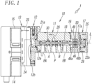
- Figs. 1 to 5 show the detailed configuration of the four-position switching valve according to the embodiment of the present invention, and the four-position switching valve has a five-port valve configuration.
- a four-position switching valve 1 has a valve body 10 extending in an axis L direction.
- the valve body 10 includes: a main body 11 having five ports EA, A, P, B, and EB from one end side in the axis L direction toward the other end side in the axis L direction; a first piston cover 12 and a pilot valve part 13 joined in sequence to one end of the main body 11 in the axis L direction; a spring cover 16 and a second piston cover 17 joined in sequence to the other end of the main body 11 in the axis L direction.
- the five ports are: a supply port P in the middle in the axis L direction; a first output port A and a second output port B located on both sides of the supply port P; a first discharging port EA located closer to the first piston cover 12 than the first output port A is; and a second discharging port EB located closer to the second piston cover 17 than the second output port B is.
- a spool 30 is inserted in the valve hole 18 so as to be slidable in the axis L direction of the valve hole 18.
- the length of the spool 30 in the axis L direction is slightly smaller than that of the valve hole 18.
- a first piston 21 (first driving part) and a second piston 22 (second driving part) slidably accommodated in piston chambers 12a and 17a are provided at one end and the other end of the spool 30 in the axis L direction so as to come into contact therewith and be separated therefrom.
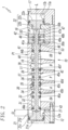
- the first piston 21 and the second piston 22 switch the spool 30 to a one-end-side switching position P1 shown in Fig. 2 , a first intermediate switching position P2 shown in Fig. 3 , a second intermediate switching position P3 shown in Fig. 4 , and another-end-side switching position P4 shown in Fig. 5 .
- the first piston 21 and the second piston 22 have the same shape.
- a pressure-receiving surface 21a of the first piston 21 faces a first pilot chamber 12b
- a pressure-receiving surface 22a of the second piston 22 faces a second pilot chamber 17b.
- the first pilot chamber 12b and the second pilot chamber 17b have the same shape.
- first piston 21 and the second piston 22 have piston body portions 21b and 22b having cylindrical shapes and projecting toward the valve hole 18, and circular flange portions 21c and 22c formed on the opposite sides of the piston body portions 21b and 22b from the valve hole 18 and projecting radially outward.
- the end faces of the flange portions 21c and 22c on the opposite sides from the piston body portions 21b and 22b form the pressure-receiving surface 21a and 22a.
- the pilot valve part 13 is provided with a first pilot valve 14 and a second pilot valve 15.
- the first pilot valve 14 and the second pilot valve 15 are disposed to one side of the first piston cover 12 in the axis L direction.
- the first pilot valve 14 is disposed on the lower side and the second pilot valve 15 is disposed on the upper side in the top-bottom direction, which is perpendicular to the axis L direction.
- the first pilot valve 14 is connected to the first pilot chamber 12b through a first pilot output path 24, and the second pilot valve 15 is connected to the second pilot chamber 17b through a second pilot output path 25.
- the pilot valves 14 and 15 are connected to the supply port P through a pilot supply path 26.
- the first and second pilot output paths 24 and 25 and the pilot supply path 26 are formed inside the valve body 10.
- a back chamber 27 facing the back surface of the first piston 21 and a back chamber 28 facing the back surface of the second piston 22 are open to the air through an open path 29 (see Fig. 3 ).
- the spool 30 is formed to have, in sequence in the axis L direction, from one end side in the axis L direction toward the other end side in the axis L direction: a first airtight portion 31, which is fitted to one end side of the valve hole 18 in the axis L direction in a slidable and airtight manner; a first circular recessed portion 32; a first land portion 33; a second circular recessed portion 34; a second land portion 35; a third circular recessed portion 36; a third land portion 37; a fourth circular recessed portion 38; a fourth land portion 39; a fifth circular recessed portion 40; and a second airtight portion 41, which is fitted to the other end side of the valve hole 18 in the axis L direction in a slidable and airtight manner.
- These portions are formed in cylindrical shapes having centers at the axis L. More specifically, the spool 30 has the circular recessed portions and the land portions, serving as valve portions, that are formed alternately in
- Sliding surfaces formed on the radially outside of the airtight portions 31 and 41 and the land portions 33, 35, 37, and 39 have circular grooves 43 that are open to the radially outside.
- Ring-shaped sealing gaskets 44a and 44b are accommodated in the grooves 43 in the airtight portions 31 and 41, and circular opening/closing gaskets 45a to 45f are accommodated in the grooves 43 in the land portions 33, 35, 37, and 39.
- the widths of the sliding surfaces of the first land portion 33 and the second land portion 35 in the axis L direction are larger than the widths of the sliding surfaces of the third land portion 37 and the fourth land portion 39, and the width of the sliding surface of the first land portion 33 is larger than the width of the sliding surface of the second land portion 35.
- two opening/closing gaskets 45a and 45b and two opening/closing gaskets 45c and 45d are fitted to the sliding surfaces of the first land portion 33 and the second land portion 35, and one gasket 45e and one gasket 45f are fitted to the sliding surfaces of the third land portion 37 and the fourth land portion 39.
- the gaskets will be described in detail below.
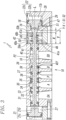
- a spool moving mechanism part 42 which selectively moves the spool 30 to the first intermediate switching position P2 (see Fig. 3 ) and the second intermediate switching position P3 (see Fig. 4 ), which are located between the one-end-side switching position P1 and the other-end-side switching position P4 (see Fig. 5 ) and differ from each other, is provided at the other side of the spool 30 in the axis L direction.
- the first intermediate switching position P2 is located closer to one side in the axial direction than the second intermediate switching position P3 is.
- the spool moving mechanism part 42 includes: a first spring washer 48a and a second spring washer 48b provided on a spring washer shaft 46, extending from the other end of the spool 30 in the axis L direction, so as to be movable in the axis L direction; and a compression spring 49 (spring member) provided between the first spring washer 48a and the second spring washer 48b.
- the spring washer shaft 46 extends from the other end of the second airtight portion 41 in the axis L direction toward the other side in the axis L direction coaxially with the spool 30 and has substantially the same outside diameter as the cylindrically formed circular recessed portions 32, 34, 36, and 38 in the spool 30.
- a pressure-receiving portion 47 extending toward the other side in the axis L direction is formed at the other end of the spring washer shaft 46 in the axis L direction.
- the pressure-receiving portion 47 extends coaxially with the spool 30, and has a larger diameter than the spring washer shaft 46 and a smaller diameter than the inside diameter of the valve hole 18.
- the other end of the spring washer shaft 46 in the axis L direction has a circular second step portion 47a facing one side in the axis L direction.
- the second step portion 47a is the end face of the pressure-receiving portion 47 on one side in the axis L direction.
- a circular first step portion 41a facing the other side in the axis L direction is formed at the one-side end of the spring washer shaft 46 in the axis L direction.
- the first step portion 41a is the end face of the second airtight portion 41 on the other side in the axis L direction.
- the spring washer shaft 46 is formed between the first step portion 41a and the second step portion 47a.
- the spring washer shaft 46 is inserted in the spring cover 16, and the first spring washer 48a and the second spring washer 48b are fitted on the spring washer shaft 46 so as to be freely movable in the axis L direction.
- the first spring washer 48a and the second spring washer 48b are formed in a disc shape and have the same shape.
- the first spring washer 48a and the second spring washer 48b have holes penetrating in the axis L direction at the centers thereof, and the spring washer shaft 46 is inserted through the holes.
- the inside diameters of the holes are slightly larger than the outside diameter of the spring washer shaft 46. Hence, the first spring washer 48a and the second spring washer 48b can move relative to the spring washer shaft 46 in the axis L direction.
- the end face of the first spring washer 48a on one side in the axial direction can be brought into contact with the first step portion 41a, and the end face of the second spring washer 48b on the other side in the axial direction can be brought into contact with the second step portion 47a.
- the coil-shaped compression spring 49 is disposed between the first spring washer 48a and the second spring washer 48b.
- the compression spring 49 is inserted between the first spring washer 48a and the second spring washer 48b in a compressed state.
- the compression spring 49 urges the first spring washer 48a and the second spring washer 48b such that the first spring washer 48a is in contact with and secured to the first step portion 41a and such that the second spring washer 48b is in contact with and secured to the second step portion 47a.
- a spring accommodating chamber 50 extending in the axis L direction is formed so as to surround the first spring washer 48a, the second spring washer 48b, and the compression spring 49.
- the spring accommodating chamber 50 has a circular cross section and has a larger diameter than the inside diameter of the valve hole 18.
- the spring accommodating chamber 50 extends from one end toward the other end side of the spring cover 16 in the axis L direction.
- a circular end wall 50a extending radially from the inside to the outside is formed at the one-side end of the spring accommodating chamber 50 in the axis L direction, and a circular end wall 50b extending radially from the inside to the outside is formed at the other-side end of the spring accommodating chamber 50 in the axis L direction.
- the length Y, in the axial direction, between the end walls 50a and 50b on both sides of the spring accommodating chamber 50 in the axis L direction (hereinbelow, “the length Y between a pair of end walls”) is larger than the length X, in the axis L direction, between the first step portion 41a and the second step portion 47a on both sides of the spring washer shaft 46 in the axial direction (hereinbelow, "the length X between a pair of step portions").
- a valve hole 18 communicating with the spring accommodating chamber 50 and extending toward the other side in the axis L direction is formed on the other side of the spring cover 16 in the axis L direction. More specifically, the valve hole 18 extends to the other end of the spring cover 16 in the axis L direction. Because the inside diameter of the valve hole 18 is larger than the outside diameters of the pressure-receiving portion 47 and the piston body portion 22b of the second piston 22, the pressure-receiving portion 47 and the second piston 22 can move in the axis L direction relative to the valve hole 18.
- the spool 30 moves to the extreme one side in the axial direction at the one-end-side switching position P1 shown in Fig. 2 and moves to the extreme other side in the axial direction at the other-end-side switching position P4 shown in Fig. 5 .
- the spool 30 moves over the distance between the one-end-side switching position P1 and the other-end-side switching position P4 (stroke length S).
- the stroke length S1, over which the spool 30 moves from one side toward the other side in the axis L direction, and the stroke length S2, over which the spool 30 moves from the other side toward one side in the axis L direction are equal. Furthermore, as shown in Figs. 3 and 5 , the stroke lengths S1 and S2 are larger than the value obtained by subtracting the length X between the pair of step portions from the length Y between the pair of end walls (Y - X); that is, Y - X ⁇ S1, S2.
- the thus-configured spool 30 of the four-position switching valve 1 is switched to the one-end-side switching position P1 in a state in which the pilot air pressure is applied to the second piston 22, the first spring washer 48a is in contact with the one end wall 50a of the spring accommodating chamber 50, and the second spring washer 48b has moved to one side in the axis L direction against the urging force of the compression spring 49. Furthermore, as shown in Fig. 2 , the thus-configured spool 30 of the four-position switching valve 1 is switched to the one-end-side switching position P1 in a state in which the pilot air pressure is applied to the second piston 22, the first spring washer 48a is in contact with the one end wall 50a of the spring accommodating chamber 50, and the second spring washer 48b has moved to one side in the axis L direction against the urging force of the compression spring 49. Furthermore, as shown in Fig.
- the spool 30 is switched to the first intermediate switching position P2 in a state in which the first spring washer 48a is in contact with the one end wall 50a of the spring accommodating chamber 50 and the first step portion 41a, and the second spring washer 48b and the spool 30 have moved toward the other side in the axis L direction due to the return force (elastic force) of the compression spring 49, so that the second spring washer 48b is in contact with the second step portion 47a.
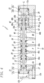
- the spool 30 is switched to the second intermediate switching position P3 in a state in which the second spring washer 48b is in contact with the other end wall 50b of the spring accommodating chamber 50, and the first spring washer 48a and the spool 30 have moved to one side in the axis L direction due to the return force (elastic force) of the compression spring 49, so that the first spring washer 48a is in contact with the first step portion 41a, and the second spring washer 48b is in contact with the second step portion 47a. Furthermore, as shown in Fig.
- the spool 30 is switched to the other-end-side switching position P4 in a state in which the pilot air pressure is applied to the first piston 21, the second spring washer 48b is in contact with the other end wall 50b of the spring accommodating chamber 50, and the first spring washer 48a has moved toward the other side in the axis L direction against the urging force of the compression spring 49.
- the spool 30 can be moved to two intermediate switching positions: the first intermediate switching position P2, to which switching is made as a result of the second spring washer 48b and the spool 30 being moved toward the other side in the axis L direction by the return force (elastic force) of the compression spring 49 when the pilot air pressure is not applied to the first piston 21 nor the second piston 22; and the second intermediate switching position P3, which is located to the other side of the first intermediate switching position P2 in the axial direction, to which switching is made as a result of the first spring washer 48a and the spool 30 being moved toward one side in the axis L direction by the return force (elastic force) of the compression spring 49.
- the first spring washer 48a moves toward one side in the axis L direction through the second spring washer 48b and the compression spring 49, which are in contact with the second step portion 47a, and comes into contact with the one end wall 50a of the spring accommodating chamber 50, and the second spring washer 48b moves toward the first spring washer 48a against the urging force of the compression spring 49.
- the spool 30 is switched to the one-end-side switching position P1 on one end side in the axis L direction.
- the second pilot valve 15 when the second pilot valve 15 is turned off in a state in which the spool 30 has been switched to the one-end-side switching position P1, as shown in Fig. 3 , the pilot air pressure supplied to the second pilot chamber 17b is eliminated, the second spring washer 48b is pressed toward the other side in the axis L direction by the return force (elastic force) of the compression spring 49, and the second spring washer 48b in contact with the second step portion 47a moves the spool 30 toward the other side in the axis L direction through the pressure-receiving portion 47. Then, when the moving distance of the spool 30 becomes equal to the width of the gap 53 in the axis L direction shown in Fig. 2 , the first step portion 41a comes into contact with the first spring washer 48a, stopping the movement of the spool 30 toward the other side in the axis L direction, and thus, the spool 30 is switched to the first intermediate switching position P2.
- a first space 51 is formed between the second spring washer 48b and the other end wall 50b of the spring accommodating chamber 50.
- the spool 30 Along with the movement of the spool 30 toward the other side in the axis L direction, the first spring washer 48a and the second spring washer 48b, which are in contact with the first step portion 41a, move toward the other side in the axis L direction, the second spring washer 48b comes into contact with the other end wall 50b of the spring accommodating chamber 50, and the first spring washer 48a moves toward the second spring washer 48b against the urging force of the compression spring 49. As a result, the spool 30 is switched to the other-end-side switching position P4.
- a second space 52 is formed between the first spring washer 48a and the one end wall 50a of the spring accommodating chamber 50.
- the width of the second space 52 in the axis L direction is equal to that of the above-described first space 51 (see Fig. 3 ).
- the four-position switching valve 1 when the spool 30 is switched to the one-end-side switching position P1, the four-position switching valve 1 becomes in a first non-communication state, in which the supply port P, the first output port A, the second output port B, and the first discharging port EA are shut off and do not communicate with one another. Furthermore, when the spool 30 is switched to the first intermediate switching position P2, as shown in Fig. 3 , the four-position switching valve 1 becomes in a first communication state, in which the first output port A and the first discharging port EA are shut off and do not communicate each other while the supply port P and the second output port B communicate with each other.
- the four-position switching valve 1 becomes in a second non-communication state, in which the supply port P, the first output port A, the second output port B, the first discharging port EA are shut off and do not communicate with one another. Furthermore, when the spool 30 is switched to the other-end-side switching position P4, as shown in Fig. 5 , the four-position switching valve 1 becomes in a second communication state, in which the second output port B, the first discharging port EA, and the second discharging port EB are shut off and do not communicate with one another while the supply port P and the first output port A communicate with each other.
- the spool 30 is provided with six, i.e., the first to the sixth, opening/closing gaskets 45a to 45f that open and close the flow paths connecting the adjoining ports and two sealing gaskets 44a and 44b that normally seal both ends of the valve hole 18, which gaskets serving as means for opening and closing the flow paths of the compressed air flowing between the adjoining ports.
- the opening/closing gaskets 45a to 45f are provided on the land portions 33, 35, 37, and 39, and the sealing gaskets 44a and 44b are provided on the first airtight portion 31 and the second airtight portion 41.
- the sixth gasket 45f counted from the first piston 21 side opens the flow path between the adjoining ports P and B when the spool 30 is switched to the first intermediate switching position P2 (see Fig. 3 ). Furthermore, the third gasket 45c counted from the first piston 21 side opens the flow path between the adjoining ports A and P when the spool 30 is switched to the other-end-side switching position P4 (see Fig. 5 ).
- the second, fourth, and sixth gaskets 45b, 45d, and 45f counted from the first piston 21 side shut off the flow paths between the adjoining ports EA, A, P, and B when the spool 30 is switched to the one-end-side switching position P1. Furthermore, as shown in Fig. 4 , the first, third, and fifth gaskets 45a, 45c, and 45e counted from the first piston 21 side shut off all the flow paths between the adjoining ports EA, A, P, and B when the spool 30 is switched to the second intermediate switching position P3.
- the two sealing gaskets 44a and 44b normally seal both ends of the valve hole 18 regardless of which switching position the spool 30 is located.
- the spring accommodating chamber 50 is formed in the valve hole 18 that accommodates one spool 30 in a manner allowing sliding thereof.
- the length Y of the spring accommodating chamber 50 in the axis L direction larger than the length X of the spring washer shaft 46 of the spool 30 in the axis L direction, and by providing the spool moving mechanism part 42 on the spring washer shaft 46 provided on the spool 30, it is possible to move the spool 30 to the two switching positions (the first intermediate switching position P2 and the second intermediate switching position P3) in addition to the one-end-side switching position P1 and the other-end-side switching position P4. Accordingly, it is possible to provide a four-position switching valve 1 that has a simple structure and that can be easily manufactured, compared with the conventional four-position switching valve, in which two spools and two return springs are provided in the valve hole.
- the configuration is not limited to this. As shown in Fig.
- a four-position switching valve 1' in which the third communication state, in which the supply port P, the second output port B, and the second discharging port EB are shut off and do not communicate with one another while the first output port A and the first discharging port EA communicate with each other, is established when the spool 30 is switched to the other-end-side switching position P4 is also possible.
- the four-position switching valve 1' shown in Fig. 6 the portions that differ from the above-described four-position switching valve 1 will be described, and the portions that are the same as those in the above-described four-position switching valve 1 will be denoted by the same reference signs, and the descriptions thereof will be omitted.
- the four-position switching valve 1' is configured such that the width of the first land portion 33 in the axis L direction is smaller than that of the second land portion 35.
- the present invention may be applied to a four-position switching valve composed of a four-port valve.
- first piston 21 and the second piston 22 have been shown as the driving parts for moving the spool 30 in the four-position switching valve 1 according to the above-described embodiment, the configuration is not limited thereto.
- the first and second pistons 21 and 22 may be omitted, and the first and second pilot chambers 12b and 17b, into which the pilot air pressure flows, may be used as the driving parts for the spool 30. In that case, it is possible to move the spool 30 in the axis L direction by directly applying the pilot air pressure to the ends of the spool 30 in the axis L direction through the first and second pilot chambers 12b and 17b.
Landscapes
- Engineering & Computer Science (AREA)
- General Engineering & Computer Science (AREA)
- Mechanical Engineering (AREA)
- Physics & Mathematics (AREA)
- Fluid Mechanics (AREA)
- Chemical & Material Sciences (AREA)
- Analytical Chemistry (AREA)
- Multiple-Way Valves (AREA)
Description
- The present invention relates to a four-position switching valve that switches a spool to four switching positions by means of pilot air pressure and a return spring.
- As disclosed in, for example,
Patent Literatures - When a pilot air pressure is applied to one piston through one pilot valve with the spring forces of the return springs being applied to the inner spool, the outer spool and the inner spool move in one direction and are switched to a one-end-side switching position, and when the pilot air pressure is applied to the other piston through the other pilot valve, the outer spool and the inner spool move in the opposite direction and are switched to the other-end-side switching position.
- When the pilot valves are turned off to release both pistons from the effect of the pilot air pressure in a state in which both spools have moved to the one-end-side switching position, the spools are switched to a first intermediate switching position by the return springs, whereas, when the pilot valves are turned off to release both pistons from the effect of the pilot air pressure in a state in which both spools have moved to the other-end-side switching position, the spools are switched to a second intermediate switching position by the return springs.
- When both spools are switched to the one-end-side switching position, the switching valve becomes in a first communication state, in which some of a plurality of ports communicate with one another while the others are shut off, and when both spools are switched to the other-end-side switching position, the switching valve becomes in a second communication state, which differs from the first communication state in the communication/shut-off relationship among the plurality of ports. When both spools are switched to the first intermediate switching position, a third communication state is established, in which some of the plurality of ports are shut off while the other ports communicate with the air, and when both spools are switched to the second intermediate switching position, the switching valve becomes in a fourth communication state, which differs from the third communication state in the shut-off/communication-with-the-air relationship among the plurality of ports.
-
GB 1 466 059 A -
US 5 353 686 A discloses a hydraulic circuit comprising a four-position closed-center valve that is controlled by a proportional control valve. The spool of the four-position selector valve has a closed-center position. Opposite ends of the spool receive a pilot pressure from the pressure proportional control valve, one position being obtained by applying pilot pressure to a first end of the spool, and two positions being obtained by applying pilot pressure to the second end of the spool. -
US 2012/255617 A1 discloses pilot-operated three position switching valve, wherein a first piston with a smaller diameter and a second piston with a larger diameter, which switch a spool between a first switching position at one end, a second switching position at the other end, and a return spring that moves the spool to a neutral switching position, are provided. -
- PTL 1:
JP 4117636 B2 - PTL 2:
JP 4277240 B2 - In these four-position switching valves disclosed in
Patent Literatures - The technical problem of the present invention is to simplify the structure of the switching valve to provide an easy-to-manufacture four-position switching valve.
- To solve this problem, a four-position switching valve according to the present invention includes: a body having a valve hole extending from one end side toward the other end side in an axial direction and a plurality of ports communicating with the valve hole; a spool accommodated in the valve hole in the body so as to be slidable in the axial direction; a first driving part that is disposed at one end of the spool in the axial direction and presses the spool toward the other end side in the axial direction to move the spool to another-end-side switching position; a second driving part that is disposed at the other end of the spool in the axial direction and presses the spool toward one end side in the axial direction to move the spool to a one-end-side switching position; and a spool moving mechanism part that selectively moves the spool to a first intermediate switching position and a second intermediate switching position, which are located between the one-end-side switching position and the other-end-side switching position and differ from each other. The communication state among the plurality of ports is switched by moving the spool to the four switching positions with the first and second driving parts and the spool moving mechanism part. The spool moving mechanism part has a spring member that accumulates an elastic force for pushing-back the spool in the direction of the one-end-side switching position as the first driving part moves the spool to the other-end-side switching position and accumulates an elastic force for pushing-back the spool in the direction of the other-end-side switching position as the second driving part moves the spool to the one-end-side switching position, whereby the spool moving mechanism part presses the spool toward the other end side in the axial direction with the elastic force of the spring member and moves the spool to the first intermediate switching position when the pressure applied to the spool by the second driving part is removed in a state in which the spool has been moved to the one-end-side switching position, and presses the spool toward the one end side in the axial direction with the elastic force of the spring member and moves the spool to the second intermediate switching position when the pressure applied to the spool by the first driving part is removed in a state in which the spool has been moved to the other-end-side switching position.
- In this case, it is preferable that: the spool has a coaxial spring washer shaft; the spool moving mechanism part further has a first spring washer at one end side in the axial direction and a second spring washer at the other end side in the axial direction on the spring washer shaft so as to be movable in the axial direction; the spring member is provided between the first spring washer and the second spring washer; the spring washer shaft has a pair of contact portions at both ends in the axial direction with which the first and second spring washers come into contact; the spring member is contracted in a state in which the first and second spring washers are in contact with the pair of contact portions; the valve hole in the body has, on both sides thereof in the axial direction with the spool moving mechanism part therebetween, a pair of stopper portions with which the first and second spring washers come into contact; and the relationships X < Y and Y - X < S1, S2 are satisfied, where X is the length between the pair of contact portions in the axial direction, Y is the length between the pair of stopper portions in the axial direction, and S1 and S2 are the stroke lengths of the spool with the first and second driving parts, respectively.
- Furthermore, it is preferable that: the valve hole is provided with a spring accommodating chamber that accommodates the spool moving mechanism part and extends in the axial direction; the spring accommodating chamber has a pair of end walls extending radially outward at both ends in the axial direction; and the pair of end walls respectively include the stopper portions with which the first and second spring washers come into contact. Furthermore, it is preferable that: the inside diameter of the spring accommodating chamber is larger than the inside diameter of the valve hole; and the outside diameters of the first spring washer and the second spring washer are larger than the inside diameter of the valve hole and smaller than the inside diameter of the spring accommodating chamber.
- Furthermore, it is preferable that: the pair of contact portions include a first step portion that projects radially outward from one end of the spring washer shaft in the axial direction and can come into contact with the first spring washer and a second step portion that projects radially outward from the other end of the spring washer shaft in the axial direction and can come into contact with the second spring washer; and the spool is switched to the first intermediate switching position in a state in which the first spring washer is in contact with the end wall and the first step portion of the spring accommodating chamber on one side in the axial direction and in which the second spring washer is in contact with the second step portion, and is switched to the second intermediate switching position in a state in which the second spring washer is in contact with the end wall and the second step portion of the spring accommodating chamber on the other side in the axial direction and in which the first spring washer is in contact with the first step portion.
- Furthermore, it is preferable that: the plurality of ports include a supply port, a first output port, a second output port, a first discharging port, and a second discharging port; a first non-communication state, in which the supply port, the first output port, the second output port, and the first discharging port are shut off and do not communicate with one another, is established at the one-end-side switching position; a first communication state, in which the first output port and the first discharging port are shut off and do not communicate with each other while the supply port and the second output port communicate with each other, is established at the first intermediate switching position; a second non-communication state, in which the supply port, the first output port, the second output port, and the first discharging port are shut off and do not communicate with one another, is established at the second intermediate switching position; and either a second communication state, in which the second output port, the first discharging port, and the second discharging port are shut off and do not communicate with one another while the supply port and the first output port communicate with each other; or a third communication state, in which the supply port, the second output port, and the second discharging port are shut off and do not communicate with one another while the first output port and the first discharging port communicate with each other, is established at the other-end-side switching position.
- As described above, the present invention can simplify the structure of the switching valve to provide an easy-to-manufacture four-position switching valve.
-
- [
Fig. 1] Fig. 1 is a relevant-part cross section of a four-position switching valve according to an embodiment of the present invention. - [
Fig. 2] Fig. 2 is a partial cross section of the four-position switching valve in a state in which a spool has been moved to a one-end-side switching position. - [
Fig. 3] Fig. 3 is a relevant-part cross section of the four-position switching valve in a state in which the spool has been moved to a first intermediate switching position. - [
Fig. 4] Fig. 4 is a partial cross section of the four-position switching valve in a state in which the spool has been moved to a second intermediate switching position. - [
Fig. 5] Fig. 5 is a relevant-part cross section of the four-position switching valve in a state in which the spool has been moved to the other-end-side switching position. - [
Fig. 6] Fig. 6 is a relevant-part cross section of a four-position switching valve according to a modification in a state in which the spool has been moved to the other-end-side switching position. - A four-position switching valve according to an embodiment of the present invention will be described below. In this embodiment, a pilot-type four-position switching valve will be described as an example. The fluid flowing through the four-position switching valve is compressed air.
-
Figs. 1 to 5 show the detailed configuration of the four-position switching valve according to the embodiment of the present invention, and the four-position switching valve has a five-port valve configuration. - As shown in
Figs. 1 and2 , a four-position switching valve 1 has avalve body 10 extending in an axis L direction. Thevalve body 10 includes: amain body 11 having five ports EA, A, P, B, and EB from one end side in the axis L direction toward the other end side in the axis L direction; afirst piston cover 12 and apilot valve part 13 joined in sequence to one end of themain body 11 in the axis L direction; aspring cover 16 and asecond piston cover 17 joined in sequence to the other end of themain body 11 in the axis L direction. - The five ports are: a supply port P in the middle in the axis L direction; a first output port A and a second output port B located on both sides of the supply port P; a first discharging port EA located closer to the
first piston cover 12 than the first output port A is; and a second discharging port EB located closer to thesecond piston cover 17 than the second output port B is. - A
valve hole 18 having a circular cross section and with which the five ports communicate penetrates through themain body 11 and thespring cover 16 in the axis L direction. Aspool 30 is inserted in thevalve hole 18 so as to be slidable in the axis L direction of thevalve hole 18. The length of thespool 30 in the axis L direction is slightly smaller than that of thevalve hole 18. A first piston 21 (first driving part) and a second piston 22 (second driving part) slidably accommodated inpiston chambers spool 30 in the axis L direction so as to come into contact therewith and be separated therefrom. - By receiving the effect of the pilot air pressure, the
first piston 21 and thesecond piston 22 switch thespool 30 to a one-end-side switching position P1 shown inFig. 2 , a first intermediate switching position P2 shown inFig. 3 , a second intermediate switching position P3 shown inFig. 4 , and another-end-side switching position P4 shown inFig. 5 . Thefirst piston 21 and thesecond piston 22 have the same shape. A pressure-receivingsurface 21a of thefirst piston 21 faces afirst pilot chamber 12b, and a pressure-receivingsurface 22a of thesecond piston 22 faces asecond pilot chamber 17b. Thefirst pilot chamber 12b and thesecond pilot chamber 17b have the same shape. - In this embodiment, the
first piston 21 and thesecond piston 22 havepiston body portions valve hole 18, andcircular flange portions piston body portions valve hole 18 and projecting radially outward. The end faces of theflange portions piston body portions surface - The
pilot valve part 13 is provided with afirst pilot valve 14 and asecond pilot valve 15. In this embodiment, thefirst pilot valve 14 and thesecond pilot valve 15 are disposed to one side of thefirst piston cover 12 in the axis L direction. Thefirst pilot valve 14 is disposed on the lower side and thesecond pilot valve 15 is disposed on the upper side in the top-bottom direction, which is perpendicular to the axis L direction. - The
first pilot valve 14 is connected to thefirst pilot chamber 12b through a firstpilot output path 24, and thesecond pilot valve 15 is connected to thesecond pilot chamber 17b through a secondpilot output path 25. Thepilot valves pilot supply path 26. The first and secondpilot output paths pilot supply path 26 are formed inside thevalve body 10. - Furthermore, a
back chamber 27 facing the back surface of thefirst piston 21 and aback chamber 28 facing the back surface of thesecond piston 22 are open to the air through an open path 29 (seeFig. 3 ). - As shown in
Fig. 2 , thespool 30 is formed to have, in sequence in the axis L direction, from one end side in the axis L direction toward the other end side in the axis L direction: a firstairtight portion 31, which is fitted to one end side of thevalve hole 18 in the axis L direction in a slidable and airtight manner; a first circular recessedportion 32; afirst land portion 33; a second circular recessedportion 34; asecond land portion 35; a third circular recessedportion 36; athird land portion 37; a fourth circular recessedportion 38; afourth land portion 39; a fifth circular recessedportion 40; and a secondairtight portion 41, which is fitted to the other end side of thevalve hole 18 in the axis L direction in a slidable and airtight manner. These portions are formed in cylindrical shapes having centers at the axis L. More specifically, thespool 30 has the circular recessed portions and the land portions, serving as valve portions, that are formed alternately in the axis L direction. - Sliding surfaces formed on the radially outside of the
airtight portions land portions circular grooves 43 that are open to the radially outside. Ring-shapedsealing gaskets grooves 43 in theairtight portions closing gaskets 45a to 45f are accommodated in thegrooves 43 in theland portions first land portion 33 and thesecond land portion 35 in the axis L direction are larger than the widths of the sliding surfaces of thethird land portion 37 and thefourth land portion 39, and the width of the sliding surface of thefirst land portion 33 is larger than the width of the sliding surface of thesecond land portion 35. Furthermore, two opening/closing gaskets closing gaskets first land portion 33 and thesecond land portion 35, and onegasket 45e and onegasket 45f are fitted to the sliding surfaces of thethird land portion 37 and thefourth land portion 39. The gaskets will be described in detail below. - A spool moving
mechanism part 42, which selectively moves thespool 30 to the first intermediate switching position P2 (seeFig. 3 ) and the second intermediate switching position P3 (seeFig. 4 ), which are located between the one-end-side switching position P1 and the other-end-side switching position P4 (seeFig. 5 ) and differ from each other, is provided at the other side of thespool 30 in the axis L direction. In this embodiment, the first intermediate switching position P2 is located closer to one side in the axial direction than the second intermediate switching position P3 is. The spool movingmechanism part 42 includes: afirst spring washer 48a and asecond spring washer 48b provided on aspring washer shaft 46, extending from the other end of thespool 30 in the axis L direction, so as to be movable in the axis L direction; and a compression spring 49 (spring member) provided between thefirst spring washer 48a and thesecond spring washer 48b. - In this embodiment, the
spring washer shaft 46 extends from the other end of the secondairtight portion 41 in the axis L direction toward the other side in the axis L direction coaxially with thespool 30 and has substantially the same outside diameter as the cylindrically formed circular recessedportions spool 30. A pressure-receivingportion 47 extending toward the other side in the axis L direction is formed at the other end of thespring washer shaft 46 in the axis L direction. The pressure-receivingportion 47 extends coaxially with thespool 30, and has a larger diameter than thespring washer shaft 46 and a smaller diameter than the inside diameter of thevalve hole 18. The other end of thespring washer shaft 46 in the axis L direction has a circularsecond step portion 47a facing one side in the axis L direction. In this embodiment, thesecond step portion 47a is the end face of the pressure-receivingportion 47 on one side in the axis L direction. - A circular
first step portion 41a facing the other side in the axis L direction is formed at the one-side end of thespring washer shaft 46 in the axis L direction. In this embodiment, thefirst step portion 41a is the end face of the secondairtight portion 41 on the other side in the axis L direction. Thespring washer shaft 46 is formed between thefirst step portion 41a and thesecond step portion 47a. Thespring washer shaft 46 is inserted in thespring cover 16, and thefirst spring washer 48a and thesecond spring washer 48b are fitted on thespring washer shaft 46 so as to be freely movable in the axis L direction. Thefirst spring washer 48a and thesecond spring washer 48b are formed in a disc shape and have the same shape. Thefirst spring washer 48a and thesecond spring washer 48b have holes penetrating in the axis L direction at the centers thereof, and thespring washer shaft 46 is inserted through the holes. The inside diameters of the holes are slightly larger than the outside diameter of thespring washer shaft 46. Hence, thefirst spring washer 48a and thesecond spring washer 48b can move relative to thespring washer shaft 46 in the axis L direction. - The end face of the
first spring washer 48a on one side in the axial direction can be brought into contact with thefirst step portion 41a, and the end face of thesecond spring washer 48b on the other side in the axial direction can be brought into contact with thesecond step portion 47a. The coil-shapedcompression spring 49 is disposed between thefirst spring washer 48a and thesecond spring washer 48b. Thecompression spring 49 is inserted between thefirst spring washer 48a and thesecond spring washer 48b in a compressed state. Thecompression spring 49 urges thefirst spring washer 48a and thesecond spring washer 48b such that thefirst spring washer 48a is in contact with and secured to thefirst step portion 41a and such that thesecond spring washer 48b is in contact with and secured to thesecond step portion 47a. - In the
valve hole 18 in thespring cover 16, aspring accommodating chamber 50 extending in the axis L direction is formed so as to surround thefirst spring washer 48a, thesecond spring washer 48b, and thecompression spring 49. Thespring accommodating chamber 50 has a circular cross section and has a larger diameter than the inside diameter of thevalve hole 18. Thespring accommodating chamber 50 extends from one end toward the other end side of thespring cover 16 in the axis L direction. Acircular end wall 50a extending radially from the inside to the outside is formed at the one-side end of thespring accommodating chamber 50 in the axis L direction, and acircular end wall 50b extending radially from the inside to the outside is formed at the other-side end of thespring accommodating chamber 50 in the axis L direction. As shown inFig. 3 , the length Y, in the axial direction, between theend walls spring accommodating chamber 50 in the axis L direction (hereinbelow, "the length Y between a pair of end walls") is larger than the length X, in the axis L direction, between thefirst step portion 41a and thesecond step portion 47a on both sides of thespring washer shaft 46 in the axial direction (hereinbelow, "the length X between a pair of step portions"). - A
valve hole 18 communicating with thespring accommodating chamber 50 and extending toward the other side in the axis L direction is formed on the other side of thespring cover 16 in the axis L direction. More specifically, thevalve hole 18 extends to the other end of thespring cover 16 in the axis L direction. Because the inside diameter of thevalve hole 18 is larger than the outside diameters of the pressure-receivingportion 47 and thepiston body portion 22b of thesecond piston 22, the pressure-receivingportion 47 and thesecond piston 22 can move in the axis L direction relative to thevalve hole 18. - Now, the distance over which the
spool 30 moves in the axis L direction, that is, the stroke length of thespool 30, will be described. In this embodiment, thespool 30 moves to the extreme one side in the axial direction at the one-end-side switching position P1 shown inFig. 2 and moves to the extreme other side in the axial direction at the other-end-side switching position P4 shown inFig. 5 . Hence, thespool 30 moves over the distance between the one-end-side switching position P1 and the other-end-side switching position P4 (stroke length S). In this embodiment, the stroke length S1, over which thespool 30 moves from one side toward the other side in the axis L direction, and the stroke length S2, over which thespool 30 moves from the other side toward one side in the axis L direction, are equal. Furthermore, as shown inFigs. 3 and5 , the stroke lengths S1 and S2 are larger than the value obtained by subtracting the length X between the pair of step portions from the length Y between the pair of end walls (Y - X); that is, Y - X < S1, S2. - Hence, when the
spool 30 that has been moved to the other-end-side switching position P4, as shown inFig. 5 , is moved toward one side in the axis L direction, as shown inFig. 2 , thesecond spring washer 48b is moved toward thefirst spring washer 48a with thefirst spring washer 48a being in contact with the oneend wall 50a, and thespool 30 can be moved to the one-end-side switching position P1. Furthermore, when thespool 30 that has been moved to the one-end-side switching position P1, as shown inFig. 2 , is moved toward the other side in the axis L direction, as shown inFig. 5 , thefirst spring washer 48a is moved toward thesecond spring washer 48b with thesecond spring washer 48b being in contact with theother end wall 50b, and thespool 30 can be moved to the other-end-side switching position P4. - As shown in
Fig. 2 , the thus-configuredspool 30 of the four-position switching valve 1 is switched to the one-end-side switching position P1 in a state in which the pilot air pressure is applied to thesecond piston 22, thefirst spring washer 48a is in contact with the oneend wall 50a of thespring accommodating chamber 50, and thesecond spring washer 48b has moved to one side in the axis L direction against the urging force of thecompression spring 49. Furthermore, as shown inFig. 3 , thespool 30 is switched to the first intermediate switching position P2 in a state in which thefirst spring washer 48a is in contact with the oneend wall 50a of thespring accommodating chamber 50 and thefirst step portion 41a, and thesecond spring washer 48b and thespool 30 have moved toward the other side in the axis L direction due to the return force (elastic force) of thecompression spring 49, so that thesecond spring washer 48b is in contact with thesecond step portion 47a. - Furthermore, as shown in
Fig. 4 , thespool 30 is switched to the second intermediate switching position P3 in a state in which thesecond spring washer 48b is in contact with theother end wall 50b of thespring accommodating chamber 50, and thefirst spring washer 48a and thespool 30 have moved to one side in the axis L direction due to the return force (elastic force) of thecompression spring 49, so that thefirst spring washer 48a is in contact with thefirst step portion 41a, and thesecond spring washer 48b is in contact with thesecond step portion 47a. Furthermore, as shown inFig. 5 , thespool 30 is switched to the other-end-side switching position P4 in a state in which the pilot air pressure is applied to thefirst piston 21, thesecond spring washer 48b is in contact with theother end wall 50b of thespring accommodating chamber 50, and thefirst spring washer 48a has moved toward the other side in the axis L direction against the urging force of thecompression spring 49. - As described, as shown in
Figs. 3 and4 , thespool 30 according to this embodiment can be moved to two intermediate switching positions: the first intermediate switching position P2, to which switching is made as a result of thesecond spring washer 48b and thespool 30 being moved toward the other side in the axis L direction by the return force (elastic force) of thecompression spring 49 when the pilot air pressure is not applied to thefirst piston 21 nor thesecond piston 22; and the second intermediate switching position P3, which is located to the other side of the first intermediate switching position P2 in the axial direction, to which switching is made as a result of thefirst spring washer 48a and thespool 30 being moved toward one side in the axis L direction by the return force (elastic force) of thecompression spring 49. - Next, the four switching positions P1, P2, P3, and P4 in the four-
position switching valve 1 according to this embodiment will be described in detail. As shown inFigs. 1 and2 , when thesecond pilot valve 15 is turned on to supply the pilot air pressure to thesecond pilot chamber 17b, thesecond piston 22 is pressed toward one side in the axis L direction by the pilot air pressure, moving thespool 30 toward one side in the axis L direction through thesecond piston 22. As thespool 30 moves toward one side in the axis L direction, thefirst spring washer 48a moves toward one side in the axis L direction through thesecond spring washer 48b and thecompression spring 49, which are in contact with thesecond step portion 47a, and comes into contact with the oneend wall 50a of thespring accommodating chamber 50, and thesecond spring washer 48b moves toward thefirst spring washer 48a against the urging force of thecompression spring 49. As a result, thespool 30 is switched to the one-end-side switching position P1 on one end side in the axis L direction. In a state in which thespool 30 has been switched to the one-end-side switching position P1, the secondairtight portion 41 of thespool 30 moves toward one side in the axis L direction, leaving agap 53 with respect to thefirst spring washer 48a. - Furthermore, when the
second pilot valve 15 is turned off in a state in which thespool 30 has been switched to the one-end-side switching position P1, as shown inFig. 3 , the pilot air pressure supplied to thesecond pilot chamber 17b is eliminated, thesecond spring washer 48b is pressed toward the other side in the axis L direction by the return force (elastic force) of thecompression spring 49, and thesecond spring washer 48b in contact with thesecond step portion 47a moves thespool 30 toward the other side in the axis L direction through the pressure-receivingportion 47. Then, when the moving distance of thespool 30 becomes equal to the width of thegap 53 in the axis L direction shown inFig. 2 , thefirst step portion 41a comes into contact with thefirst spring washer 48a, stopping the movement of thespool 30 toward the other side in the axis L direction, and thus, thespool 30 is switched to the first intermediate switching position P2. - In a state in which the
spool 30 has been switched to the first intermediate switching position P2, afirst space 51 is formed between thesecond spring washer 48b and theother end wall 50b of thespring accommodating chamber 50. - Furthermore, as shown in
Figs. 1 and5 , when thefirst pilot valve 14 is turned on to supply the pilot air pressure to thefirst pilot chamber 12b, thefirst piston 21 is pressed toward the other side in the axis L direction by the pilot air pressure, moving thespool 30 toward the other side in the axis L direction through thefirst piston 21. Along with the movement of thespool 30 toward the other side in the axis L direction, thefirst spring washer 48a and thesecond spring washer 48b, which are in contact with thefirst step portion 41a, move toward the other side in the axis L direction, thesecond spring washer 48b comes into contact with theother end wall 50b of thespring accommodating chamber 50, and thefirst spring washer 48a moves toward thesecond spring washer 48b against the urging force of thecompression spring 49. As a result, thespool 30 is switched to the other-end-side switching position P4. In a state in which thespool 30 has been switched to the other-end-side switching position P4, the pressure-receivingportion 47 of thespool 30 moves toward the other side in the axis L direction, leaving agap 54 with respect to thesecond spring washer 48b. - Furthermore, as shown in
Figs. 1 and5 , in a state in which thespool 30 has been moved to the other-end-side switching position P4, when thefirst pilot valve 14 is turned off, as shown inFig. 4 , the pilot air pressure supplied to thefirst pilot chamber 12b is eliminated, thefirst spring washer 48a is pressed toward one side in the axis L direction by the return force (elastic force) of thecompression spring 49, and thespool 30 moves toward one side in the axis L direction along with the movement of thefirst spring washer 48a, which is in contact with thefirst step portion 41a, toward one side in the axis L direction. At this time, when the moving distance of thespool 30 becomes equal to the width of thegap 54 in the axis L direction shown inFig. 5 , thesecond spring washer 48b comes into contact with thesecond step portion 47a, stopping the movement of thespool 30 toward one side in the axis L direction, and thus, thespool 30 is switched to the second intermediate switching position P3. - In a state in which the
spool 30 has been switched to the second intermediate switching position P3, asecond space 52 is formed between thefirst spring washer 48a and the oneend wall 50a of thespring accommodating chamber 50. The width of thesecond space 52 in the axis L direction is equal to that of the above-described first space 51 (seeFig. 3 ). - As shown in
Fig. 2 , when thespool 30 is switched to the one-end-side switching position P1, the four-position switching valve 1 becomes in a first non-communication state, in which the supply port P, the first output port A, the second output port B, and the first discharging port EA are shut off and do not communicate with one another. Furthermore, when thespool 30 is switched to the first intermediate switching position P2, as shown inFig. 3 , the four-position switching valve 1 becomes in a first communication state, in which the first output port A and the first discharging port EA are shut off and do not communicate each other while the supply port P and the second output port B communicate with each other. - Furthermore, when the
spool 30 is switched to the second intermediate switching position P3, as shown inFig. 4 , the four-position switching valve 1 becomes in a second non-communication state, in which the supply port P, the first output port A, the second output port B, the first discharging port EA are shut off and do not communicate with one another. Furthermore, when thespool 30 is switched to the other-end-side switching position P4, as shown inFig. 5 , the four-position switching valve 1 becomes in a second communication state, in which the second output port B, the first discharging port EA, and the second discharging port EB are shut off and do not communicate with one another while the supply port P and the first output port A communicate with each other. - As shown in
Fig. 2 , thespool 30 is provided with six, i.e., the first to the sixth, opening/closing gaskets 45a to 45f that open and close the flow paths connecting the adjoining ports and two sealinggaskets valve hole 18, which gaskets serving as means for opening and closing the flow paths of the compressed air flowing between the adjoining ports. The opening/closing gaskets 45a to 45f are provided on theland portions gaskets airtight portion 31 and the secondairtight portion 41. - Among the six opening/closing gaskets (hereinbelow, simply "gaskets") 45a to 45f, the
sixth gasket 45f counted from thefirst piston 21 side opens the flow path between the adjoining ports P and B when thespool 30 is switched to the first intermediate switching position P2 (seeFig. 3 ). Furthermore, thethird gasket 45c counted from thefirst piston 21 side opens the flow path between the adjoining ports A and P when thespool 30 is switched to the other-end-side switching position P4 (seeFig. 5 ). - Furthermore, the second, fourth, and
sixth gaskets first piston 21 side shut off the flow paths between the adjoining ports EA, A, P, and B when thespool 30 is switched to the one-end-side switching position P1. Furthermore, as shown inFig. 4 , the first, third, andfifth gaskets first piston 21 side shut off all the flow paths between the adjoining ports EA, A, P, and B when thespool 30 is switched to the second intermediate switching position P3. - Meanwhile, the two sealing
gaskets valve hole 18 regardless of which switching position thespool 30 is located. - In the thus-configured four-
position switching valve 1, thespring accommodating chamber 50 is formed in thevalve hole 18 that accommodates onespool 30 in a manner allowing sliding thereof. By making the length Y of thespring accommodating chamber 50 in the axis L direction larger than the length X of thespring washer shaft 46 of thespool 30 in the axis L direction, and by providing the spool movingmechanism part 42 on thespring washer shaft 46 provided on thespool 30, it is possible to move thespool 30 to the two switching positions (the first intermediate switching position P2 and the second intermediate switching position P3) in addition to the one-end-side switching position P1 and the other-end-side switching position P4. Accordingly, it is possible to provide a four-position switching valve 1 that has a simple structure and that can be easily manufactured, compared with the conventional four-position switching valve, in which two spools and two return springs are provided in the valve hole. - Furthermore, as shown in
Figs. 2 and3 , in an emergency, such as when the power supply to the second pilot valve 15 (seeFig. 1 ) is shut off in a state in which thespool 30 has been switched to the one-end-side switching position P1, it is possible to switch thespool 30 to the first intermediate switching position P2, in which the supply port P and the second output port B communicate with each other, with the return force (elastic force) of thecompression spring 49. Therefore, for example, when a vacuum generator, such as an ejector, is connected to the second output port B, because it is possible to maintain the vacuum generator in an operating state in an emergency, and thus, it is possible to maintain the vacuum state of the device that has been brought to a vacuum by the vacuum generator. - Furthermore, as shown in
Figs. 4 and5 , in an emergency, such as when the power supply to the first pilot valve 14 (seeFig. 1 ) is shut off in a state in which thespool 30 has been switched to the other-end-side switching position P4, it is possible to switch thespool 30 to the second intermediate switching position P3, in which the flow paths between the ports EA, A, P, and B are all shut off, with the return force (elastic force) of thecompression spring 49. Therefore, for example, when a vacuum generator, such as an ejector, is connected to the second output port B, it is possible to stop vacuum breaking of the device in a non-operating state of the vacuum generator at the time of an emergency. - In the four-
position switching valve 1 according to the above-described embodiment, the case where the second communication state, in which the second output port B, the first discharging port EA, and the second discharging port EB are shut off and do not communicate with one another while the supply port P and the first output port A communicate with each other, is established when thespool 30 is switched to the other-end-side switching position P4 has been described. However, the configuration is not limited to this. As shown inFig. 6 , a four-position switching valve 1' in which the third communication state, in which the supply port P, the second output port B, and the second discharging port EB are shut off and do not communicate with one another while the first output port A and the first discharging port EA communicate with each other, is established when thespool 30 is switched to the other-end-side switching position P4 is also possible. Note that, regarding the four-position switching valve 1' shown inFig. 6 , the portions that differ from the above-described four-position switching valve 1 will be described, and the portions that are the same as those in the above-described four-position switching valve 1 will be denoted by the same reference signs, and the descriptions thereof will be omitted. - In this case, the four-position switching valve 1' is configured such that the width of the
first land portion 33 in the axis L direction is smaller than that of thesecond land portion 35. With this configuration, when thespool 30 is switched to the other-end-side switching position P4, thefirst gasket 45a counted from thefirst piston 21 side opens the flow path between the adjoining ports EA and A, and thethird gasket 45c counted from thefirst piston 21 side shuts off the supply port P and the first output port A so as not to communicate with each other. - Therefore, for example, when a device to be brought to a vacuum is connected to the first output port A, once the
spool 30 is switched to the other-end-side switching position P4, the atmospheric pressure flows into the device from the port EA through the first output port A, enabling the vacuum state of the device to be broken. - Although the illustrated four-
position switching valves 1 and 1' are configured as five-port valves, the present invention may be applied to a four-position switching valve composed of a four-port valve. Furthermore, although thefirst piston 21 and thesecond piston 22 have been shown as the driving parts for moving thespool 30 in the four-position switching valve 1 according to the above-described embodiment, the configuration is not limited thereto. The first andsecond pistons second pilot chambers spool 30. In that case, it is possible to move thespool 30 in the axis L direction by directly applying the pilot air pressure to the ends of thespool 30 in the axis L direction through the first andsecond pilot chambers -
- 1, 1' four-position switching valve
- 10 valve body (body)
- 11 main body
- 12 first piston cover
- 12a, 17a piston chamber
- 12b first pilot chamber
- 13 pilot valve part
- 14 first pilot valve
- 15 second pilot valve
- 16 spring cover
- 17 second piston cover
- 17b second pilot chamber
- 18 valve hole
- 21 first piston (first driving part)
- 21a and 22a pressure-receiving surface
- 21b, 22b piston body portion
- 21c and 22c flange portion
- 22 second piston (second driving part)
- 24 first pilot output path
- 25 second pilot output path
- 26 pilot supply path
- 27, 28 back chamber
- 29 open path
- 30 spool
- 31 first airtight portion
- 32 first circular recessed portion
- 33 first land portion
- 34 second circular recessed portion
- 35 second land portion
- 36 third circular recessed portion
- 37 third land portion
- 38 fourth circular recessed portion
- 39 fourth land portion
- 40 fifth circular recessed portion
- 41 second airtight portion
- 41a first step portion (contact portion)
- 42 spool moving mechanism part
- 43 groove
- 44a and 44b sealing gasket
- 45a, 45b, 45c, 45d, 45e, 45f opening/closing gasket
- 46 spring washer shaft
- 47 pressure-receiving portion
- 47a second step portion (contact portion)
- 48a first spring washer
- 48b second spring washer
- 49 compression spring (spring member)
- 50 spring accommodating chamber
- 50a one end wall (stopper portion)
- 50b the other end wall (stopper portion)
- 51 first space portion
- 52 second space portion
- 53, 54 gap
- A first output port (port)
- B second output port (port)
- EA first discharging port (port)
- EB second discharging port (port)
- L axis
- P supply port (port)
- P1 one-end-side switching position
- P2 first intermediate switching position
- P3 second intermediate switching position
- P4 the other-end-side switching position
Claims (6)
- A four-position switching valve (1, 1') comprising:a body (10) having a valve hole (18) extending from one end side toward the other end side in an axis (L) direction and a plurality of ports (EA, A, P, B, and EB) communicating with the valve hole (18);a spool (30) accommodated in the valve hole (18) in the body (10) so as to be slidable in the axis (L) direction;a first driving part (21) that is disposed at one end of the spool (30) in the axial direction and presses the spool (30) toward the other end side in the axial direction to move the spool to another-end-side switching position (P4);a second driving part (22) that is disposed at the other end of the spool (30) in the axial direction and presses the spool (30) toward one end side in the axial direction to move the spool to a one-end-side switching position (P1);
characterized in thata spool moving mechanism part (42) that selectively moves the spool (30) to a first intermediate switching position (P2) and a second intermediate switching position (P3), which are located between the one-end-side switching position (P1) and the other-end-side switching position (P4) and differ from each other, the communication state among the plurality of ports (EA, A, P, B, and EB) being switched by moving the spool (30) to the four switching positions (P1, P2, P3, and P4) with the first and second driving parts (21 and 22) and the spool moving mechanism part (42),wherein the spool moving mechanism part (42) has a spring member (49) that accumulates an elastic force for pushing-back the spool (30) in the direction of the one-end-side switching position (P1) as the first driving part (21) moves the spool (30) to the other-end-side switching position (P4) and accumulates an elastic force for pushing-back the spool (30) in the direction of the other-end-side switching position (P4) as the second driving part (22) moves the spool (30) to the one-end-side switching position (P1), whereby the spool moving mechanism part (42) presses the spool (30) toward the other end side in the axial direction with the elastic force of the spring member (49) and moves the spool to the first intermediate switching position (P2) when the pressure applied to the spool (30) by the second driving part (22) is removed in a state in which the spool (30) has been moved to the one-end-side switching position (P1), and presses the spool (30) toward the one end side in the axial direction with the elastic force of the spring member (49) and moves the spool to the second intermediate switching position (P3) when the pressure applied to the spool (30) by the first driving part (21) is removed in a state in which the spool (30) has been moved to the other-end-side switching position (P4). - The four-position switching valve (1, 1') according to Claim 1, whereinthe spool (30) has a coaxial spring washer shaft (46),the spool moving mechanism part (42) further has a first spring washer (48a) at one end side in the axial direction and a second spring washer (48b) at the other end side in the axial direction on the spring washer shaft (46) so as to be movable in the axial direction,the spring member (49) is provided between the first spring washer (48a) and the second spring washer (48b),the spring washer shaft (46) has a pair of contact portions (41a and 47a) at both ends in the axis (L) direction with which the first and second spring washers (48a and 48b) come into contact,the spring member (49) is contracted in a state in which the first and second spring washers (48a and 48b) are in contact with the pair of contact portions (41a and 47a),the valve hole (18) in the body (10) has, on both sides thereof in the axial direction with the spool moving mechanism part (42) therebetween, a pair of stopper portions (50a and 50b) with which the first and second spring washers (48a and 48b) come into contact, andthe relationships X < Y and Y - X < S1, S2 are satisfied, where X is the length between the pair of contact portions (41a and 47a) in the axial direction, Y is the length between the pair of stopper portions (50a and 50b) in the axial direction, and S1 and S2 are the stroke lengths of the spool (30) with the first and second driving parts (21 and 22), respectively.
- The four-position switching valve (1, 1') according to Claim 2, whereinthe valve hole (18) is provided with a spring accommodating chamber (50) that accommodates the spool moving mechanism part (42) and extends in the axial direction,the spring accommodating chamber (50) has a pair of end walls (50a and 50b) extending radially outward at both ends in the axial direction, andthe pair of end walls (50a and 50b) respectively include the stopper portions (50a and 50b) with which the first and second spring washers (48a and 48b) come into contact.
- The four-position switching valve (1, 1') according to Claim 3, whereinthe inside diameter of the spring accommodating chamber (50) is larger than the inside diameter of the valve hole (18), andthe outside diameters of the first spring washer (48a) and the second spring washer (48b) are larger than the inside diameter of the valve hole (18) and smaller than the inside diameter of the spring accommodating chamber (50).
- The four-position switching valve (1, 1') according to Claim 3, whereinthe pair of contact portions (41a and 47a) include a first step portion (41a) that projects radially outward from one end of the spring washer shaft (46) in the axis (L) direction and can come into contact with the first spring washer (48a) and a second step portion (47a) that projects radially outward from the other end of the spring washer shaft (46) in the axial direction and can come into contact with the second spring washer (48b), andthe spool (30) is switched to the first intermediate switching position (P2) in a state in which the first spring washer (48a) is in contact with the first step portion (41a) and the end wall (50a) of the spring accommodating chamber (50) on one side in the axial direction and in which the second spring washer (48b) is in contact with the second step portion (47a), and is switched to the second intermediate switching position (P3) in a state in which the second spring washer (48b) is in contact with the second step portion (47a) and the end wall (50b) of the spring accommodating chamber (50) on the other side in the axial direction and in which the first spring washer (48a) is in contact with the first step portion (41a).
- The four-position switching valve (1, 1') according to Claim 1, whereinthe plurality of ports (EA, A, P, B, and EB) include a supply port (P), a first output port (A), a second output port (B), a first discharging port (EA), and a second discharging port (EB),a first non-communication state, in which the supply port (P), the first output port (A), the second output port (B), and the first discharging port (EA) are shut off and do not communicate with one another, is established at the one-end-side switching position (P1),a first communication state, in which the first output port (A) and the first discharging port (EA) are shut off and do not communicate with each other while the supply port (P) and the second output port (B) communicate with each other, is established at the first intermediate switching position (P2),a second non-communication state, in which the supply port (P), the first output port (A), the second output port (B), and the first discharging port (EA) are all shut off and do not communicate with one another, is established at the second intermediate switching position (P3), andeither a second communication state, in which the second output port (B), the first discharging port (EA), and the second discharging port (EB) are shut off and do not communicate with one another while the supply port (P) and the first output port (A) communicate with each other, or a third communication state, in which the supply port (P), the second output port (B), and the second discharging port (EB) are shut off and do not communicate with one another while the first output port (A) and the first discharging port (EA) communicate with each other, is established at the other-end-side switching position (P4).
Applications Claiming Priority (1)
| Application Number | Priority Date | Filing Date | Title |
|---|---|---|---|
| JP2021069090A JP7622530B2 (en) | 2021-04-15 | 2021-04-15 | 4-position switching valve |
Publications (2)
| Publication Number | Publication Date |
|---|---|
| EP4074987A1 EP4074987A1 (en) | 2022-10-19 |
| EP4074987B1 true EP4074987B1 (en) | 2024-07-31 |
Family
ID=81326082
Family Applications (1)
| Application Number | Title | Priority Date | Filing Date |
|---|---|---|---|
| EP22167024.3A Active EP4074987B1 (en) | 2021-04-15 | 2022-04-06 | Four-position switching valve |
Country Status (6)
| Country | Link |
|---|---|
| US (1) | US11680650B2 (en) |
| EP (1) | EP4074987B1 (en) |
| JP (1) | JP7622530B2 (en) |
| KR (1) | KR20220142924A (en) |
| CN (1) | CN115217996A (en) |
| TW (1) | TWI899440B (en) |
Families Citing this family (1)
| Publication number | Priority date | Publication date | Assignee | Title |
|---|---|---|---|---|
| CN118728998B (en) * | 2024-08-30 | 2024-11-15 | 宁波索诺工业自控设备有限公司 | Explosion-proof two-position five-way electromagnetic reversing valve |
Citations (10)
| Publication number | Priority date | Publication date | Assignee | Title |
|---|---|---|---|---|
| GB1466059A (en) | 1974-04-08 | 1977-03-02 | Pressure Dynamics Ltd | Valves and hydraulic circuits |
| US5353686A (en) | 1992-05-25 | 1994-10-11 | Kabushiki Kaisha Komatsu Seisakusho | Hydraulic circuit for four-position closed-center selector valve controlled by pressure proportional control valve |
| JP4117636B2 (en) | 1998-10-23 | 2008-07-16 | Smc株式会社 | Solenoid valve for energy saving drive |
| JP4277240B2 (en) | 1998-08-05 | 2009-06-10 | Smc株式会社 | Solenoid valve for energy saving drive |
| US20120255617A1 (en) | 2011-04-07 | 2012-10-11 | SMC Coporation | Pilot-operated three-position switching valve |
| EP2577122B1 (en) | 2011-07-26 | 2013-09-25 | FESTO AG & Co. KG | Multiple way valve and method of actuating |
| DE102016205722B3 (en) | 2016-04-06 | 2016-12-15 | Festo Ag & Co. Kg | Multi-way valve |
| DE102011010566B4 (en) | 2010-02-10 | 2019-02-28 | Smc Corporation | Dekompressionsschaltventil |
| DE102016224525B4 (en) | 2016-12-08 | 2019-07-11 | Festo Ag & Co. Kg | Multiway valve and method for its operation |
| DE102020133997B4 (en) | 2020-12-17 | 2023-06-22 | Festo Se & Co. Kg | multi-way valve |
Family Cites Families (5)
| Publication number | Priority date | Publication date | Assignee | Title |
|---|---|---|---|---|
| US3160174A (en) * | 1961-03-28 | 1964-12-08 | Parker Hannifin Corp | Remote power shift circuits for spool valves and the like |
| US4355660A (en) * | 1980-04-15 | 1982-10-26 | General Signal Corporation | Pneumatically controlled, four position hydraulic valve |
| US4354527A (en) * | 1980-10-09 | 1982-10-19 | Caterpillar Tractor Co. | Control system for pilot operated valve |
| DE3909988C1 (en) * | 1989-03-25 | 1990-05-23 | O & K Orenstein & Koppel Ag, 1000 Berlin, De | |
| JP6007872B2 (en) * | 2013-08-29 | 2016-10-12 | Smc株式会社 | Double solenoid valve |
-
2021
- 2021-04-15 JP JP2021069090A patent/JP7622530B2/en active Active
-
2022
- 2022-02-23 TW TW111106558A patent/TWI899440B/en active
- 2022-03-23 US US17/656,093 patent/US11680650B2/en active Active
- 2022-03-28 KR KR1020220037960A patent/KR20220142924A/en active Pending
- 2022-04-06 EP EP22167024.3A patent/EP4074987B1/en active Active
- 2022-04-14 CN CN202210390613.5A patent/CN115217996A/en active Pending
Patent Citations (10)
| Publication number | Priority date | Publication date | Assignee | Title |
|---|---|---|---|---|
| GB1466059A (en) | 1974-04-08 | 1977-03-02 | Pressure Dynamics Ltd | Valves and hydraulic circuits |
| US5353686A (en) | 1992-05-25 | 1994-10-11 | Kabushiki Kaisha Komatsu Seisakusho | Hydraulic circuit for four-position closed-center selector valve controlled by pressure proportional control valve |
| JP4277240B2 (en) | 1998-08-05 | 2009-06-10 | Smc株式会社 | Solenoid valve for energy saving drive |
| JP4117636B2 (en) | 1998-10-23 | 2008-07-16 | Smc株式会社 | Solenoid valve for energy saving drive |
| DE102011010566B4 (en) | 2010-02-10 | 2019-02-28 | Smc Corporation | Dekompressionsschaltventil |
| US20120255617A1 (en) | 2011-04-07 | 2012-10-11 | SMC Coporation | Pilot-operated three-position switching valve |
| EP2577122B1 (en) | 2011-07-26 | 2013-09-25 | FESTO AG & Co. KG | Multiple way valve and method of actuating |
| DE102016205722B3 (en) | 2016-04-06 | 2016-12-15 | Festo Ag & Co. Kg | Multi-way valve |
| DE102016224525B4 (en) | 2016-12-08 | 2019-07-11 | Festo Ag & Co. Kg | Multiway valve and method for its operation |
| DE102020133997B4 (en) | 2020-12-17 | 2023-06-22 | Festo Se & Co. Kg | multi-way valve |
Also Published As
| Publication number | Publication date |
|---|---|
| JP2022163935A (en) | 2022-10-27 |
| JP7622530B2 (en) | 2025-01-28 |
| KR20220142924A (en) | 2022-10-24 |
| TWI899440B (en) | 2025-10-01 |
| TW202242285A (en) | 2022-11-01 |
| US11680650B2 (en) | 2023-06-20 |
| CN115217996A (en) | 2022-10-21 |
| EP4074987A1 (en) | 2022-10-19 |
| US20220333702A1 (en) | 2022-10-20 |
Similar Documents
| Publication | Publication Date | Title |
|---|---|---|
| US8925587B2 (en) | Pilot-operated three-position switching valve | |
| KR101691430B1 (en) | Five-port switching valve with residual pressure exhaust valve | |
| US5535783A (en) | Balanced type direct-acting electromagnetic valve | |
| US5558126A (en) | Double solenoid type electromagnetic valve | |
| CN104832700B (en) | Solenoid-operated pilot type spool valve | |
| KR20170045228A (en) | Dual 4-port electromagnetic valve | |
| KR19990063093A (en) | Electronic Pilot Operated 3 Position Valve | |
| JP2014512496A (en) | Poppet valve assembly for controlling pneumatic actuators | |
| US4353392A (en) | Safety valve assembly | |
| EP4074987B1 (en) | Four-position switching valve | |
| EP0898103B1 (en) | Three-port solenoid valve using valve body for five-port solenoid valve | |
| JP3763184B2 (en) | Switching valve | |
| JP2001050406A (en) | Multi-way valve | |
| CN102996861A (en) | Electromagnetic pilot-operated type high pressure double-channel control valve | |
| JP2001280519A (en) | Three-port solenoid valve | |
| CN213236189U (en) | High-response two-way cartridge valve | |
| JPH10332006A (en) | Switching valve | |
| CN214331567U (en) | Two-way load proportional reversing valve | |
| EP3594510B1 (en) | Control valve | |
| KR20240047918A (en) | Valve for controlling fluid flows | |
| US20140352826A1 (en) | Directional poppet valve | |
| JP5794947B2 (en) | Directional control valve | |
| JPS5934912B2 (en) | hydraulic switching valve | |
| CN110966428A (en) | a hydraulic control valve | |
| JPH042836B2 (en) |
Legal Events
| Date | Code | Title | Description |
|---|---|---|---|
| PUAI | Public reference made under article 153(3) epc to a published international application that has entered the european phase |
Free format text: ORIGINAL CODE: 0009012 |
|
| STAA | Information on the status of an ep patent application or granted ep patent |
Free format text: STATUS: THE APPLICATION HAS BEEN PUBLISHED |
|
| AK | Designated contracting states |
Kind code of ref document: A1 Designated state(s): AL AT BE BG CH CY CZ DE DK EE ES FI FR GB GR HR HU IE IS IT LI LT LU LV MC MK MT NL NO PL PT RO RS SE SI SK SM TR |
|
| STAA | Information on the status of an ep patent application or granted ep patent |
Free format text: STATUS: REQUEST FOR EXAMINATION WAS MADE |
|
| 17P | Request for examination filed |
Effective date: 20230405 |
|
| RBV | Designated contracting states (corrected) |
Designated state(s): AL AT BE BG CH CY CZ DE DK EE ES FI FR GB GR HR HU IE IS IT LI LT LU LV MC MK MT NL NO PL PT RO RS SE SI SK SM TR |
|
| GRAP | Despatch of communication of intention to grant a patent |
Free format text: ORIGINAL CODE: EPIDOSNIGR1 |
|
| STAA | Information on the status of an ep patent application or granted ep patent |
Free format text: STATUS: GRANT OF PATENT IS INTENDED |
|
| RIC1 | Information provided on ipc code assigned before grant |
Ipc: F15B 13/04 20060101ALN20240219BHEP Ipc: F16K 11/02 20060101ALI20240219BHEP Ipc: F15B 20/00 20060101ALI20240219BHEP Ipc: F15B 13/043 20060101AFI20240219BHEP |
|
| INTG | Intention to grant announced |
Effective date: 20240311 |
|
| RIC1 | Information provided on ipc code assigned before grant |
Ipc: F15B 13/04 20060101ALN20240223BHEP Ipc: F16K 11/02 20060101ALI20240223BHEP Ipc: F15B 20/00 20060101ALI20240223BHEP Ipc: F15B 13/043 20060101AFI20240223BHEP |
|
| GRAS | Grant fee paid |
Free format text: ORIGINAL CODE: EPIDOSNIGR3 |
|
| GRAA | (expected) grant |
Free format text: ORIGINAL CODE: 0009210 |
|
| STAA | Information on the status of an ep patent application or granted ep patent |
Free format text: STATUS: THE PATENT HAS BEEN GRANTED |
|
| AK | Designated contracting states |
Kind code of ref document: B1 Designated state(s): AL AT BE BG CH CY CZ DE DK EE ES FI FR GB GR HR HU IE IS IT LI LT LU LV MC MK MT NL NO PL PT RO RS SE SI SK SM TR |
|
| REG | Reference to a national code |
Ref country code: CH Ref legal event code: EP Ref country code: GB Ref legal event code: FG4D |
|
| REG | Reference to a national code |
Ref country code: DE Ref legal event code: R096 Ref document number: 602022004887 Country of ref document: DE |
|
| REG | Reference to a national code |
Ref country code: IE Ref legal event code: FG4D |
|
| REG | Reference to a national code |
Ref country code: LT Ref legal event code: MG9D |
|
| REG | Reference to a national code |
Ref country code: NL Ref legal event code: MP Effective date: 20240731 |
|
| PG25 | Lapsed in a contracting state [announced via postgrant information from national office to epo] |
Ref country code: PT Free format text: LAPSE BECAUSE OF FAILURE TO SUBMIT A TRANSLATION OF THE DESCRIPTION OR TO PAY THE FEE WITHIN THE PRESCRIBED TIME-LIMIT Effective date: 20241202 |
|
| REG | Reference to a national code |
Ref country code: AT Ref legal event code: MK05 Ref document number: 1708692 Country of ref document: AT Kind code of ref document: T Effective date: 20240731 |
|
| PG25 | Lapsed in a contracting state [announced via postgrant information from national office to epo] |
Ref country code: PT Free format text: LAPSE BECAUSE OF FAILURE TO SUBMIT A TRANSLATION OF THE DESCRIPTION OR TO PAY THE FEE WITHIN THE PRESCRIBED TIME-LIMIT Effective date: 20241202 |
|
| PG25 | Lapsed in a contracting state [announced via postgrant information from national office to epo] |
Ref country code: NO Free format text: LAPSE BECAUSE OF FAILURE TO SUBMIT A TRANSLATION OF THE DESCRIPTION OR TO PAY THE FEE WITHIN THE PRESCRIBED TIME-LIMIT Effective date: 20241031 |
|
| PG25 | Lapsed in a contracting state [announced via postgrant information from national office to epo] |
Ref country code: FI Free format text: LAPSE BECAUSE OF FAILURE TO SUBMIT A TRANSLATION OF THE DESCRIPTION OR TO PAY THE FEE WITHIN THE PRESCRIBED TIME-LIMIT Effective date: 20240731 Ref country code: NL Free format text: LAPSE BECAUSE OF FAILURE TO SUBMIT A TRANSLATION OF THE DESCRIPTION OR TO PAY THE FEE WITHIN THE PRESCRIBED TIME-LIMIT Effective date: 20240731 Ref country code: GR Free format text: LAPSE BECAUSE OF FAILURE TO SUBMIT A TRANSLATION OF THE DESCRIPTION OR TO PAY THE FEE WITHIN THE PRESCRIBED TIME-LIMIT Effective date: 20241101 Ref country code: PL Free format text: LAPSE BECAUSE OF FAILURE TO SUBMIT A TRANSLATION OF THE DESCRIPTION OR TO PAY THE FEE WITHIN THE PRESCRIBED TIME-LIMIT Effective date: 20240731 |
|
| PG25 | Lapsed in a contracting state [announced via postgrant information from national office to epo] |
Ref country code: BG Free format text: LAPSE BECAUSE OF FAILURE TO SUBMIT A TRANSLATION OF THE DESCRIPTION OR TO PAY THE FEE WITHIN THE PRESCRIBED TIME-LIMIT Effective date: 20240731 |
|
| PG25 | Lapsed in a contracting state [announced via postgrant information from national office to epo] |
Ref country code: LV Free format text: LAPSE BECAUSE OF FAILURE TO SUBMIT A TRANSLATION OF THE DESCRIPTION OR TO PAY THE FEE WITHIN THE PRESCRIBED TIME-LIMIT Effective date: 20240731 |
|
| PG25 | Lapsed in a contracting state [announced via postgrant information from national office to epo] |
Ref country code: IS Free format text: LAPSE BECAUSE OF FAILURE TO SUBMIT A TRANSLATION OF THE DESCRIPTION OR TO PAY THE FEE WITHIN THE PRESCRIBED TIME-LIMIT Effective date: 20241130 Ref country code: AT Free format text: LAPSE BECAUSE OF FAILURE TO SUBMIT A TRANSLATION OF THE DESCRIPTION OR TO PAY THE FEE WITHIN THE PRESCRIBED TIME-LIMIT Effective date: 20240731 |
|
| PG25 | Lapsed in a contracting state [announced via postgrant information from national office to epo] |
Ref country code: HR Free format text: LAPSE BECAUSE OF FAILURE TO SUBMIT A TRANSLATION OF THE DESCRIPTION OR TO PAY THE FEE WITHIN THE PRESCRIBED TIME-LIMIT Effective date: 20240731 |
|
| PG25 | Lapsed in a contracting state [announced via postgrant information from national office to epo] |
Ref country code: ES Free format text: LAPSE BECAUSE OF FAILURE TO SUBMIT A TRANSLATION OF THE DESCRIPTION OR TO PAY THE FEE WITHIN THE PRESCRIBED TIME-LIMIT Effective date: 20240731 Ref country code: RS Free format text: LAPSE BECAUSE OF FAILURE TO SUBMIT A TRANSLATION OF THE DESCRIPTION OR TO PAY THE FEE WITHIN THE PRESCRIBED TIME-LIMIT Effective date: 20241031 |
|
| PG25 | Lapsed in a contracting state [announced via postgrant information from national office to epo] |
Ref country code: RS Free format text: LAPSE BECAUSE OF FAILURE TO SUBMIT A TRANSLATION OF THE DESCRIPTION OR TO PAY THE FEE WITHIN THE PRESCRIBED TIME-LIMIT Effective date: 20241031 Ref country code: PL Free format text: LAPSE BECAUSE OF FAILURE TO SUBMIT A TRANSLATION OF THE DESCRIPTION OR TO PAY THE FEE WITHIN THE PRESCRIBED TIME-LIMIT Effective date: 20240731 Ref country code: NO Free format text: LAPSE BECAUSE OF FAILURE TO SUBMIT A TRANSLATION OF THE DESCRIPTION OR TO PAY THE FEE WITHIN THE PRESCRIBED TIME-LIMIT Effective date: 20241031 Ref country code: NL Free format text: LAPSE BECAUSE OF FAILURE TO SUBMIT A TRANSLATION OF THE DESCRIPTION OR TO PAY THE FEE WITHIN THE PRESCRIBED TIME-LIMIT Effective date: 20240731 Ref country code: LV Free format text: LAPSE BECAUSE OF FAILURE TO SUBMIT A TRANSLATION OF THE DESCRIPTION OR TO PAY THE FEE WITHIN THE PRESCRIBED TIME-LIMIT Effective date: 20240731 Ref country code: IS Free format text: LAPSE BECAUSE OF FAILURE TO SUBMIT A TRANSLATION OF THE DESCRIPTION OR TO PAY THE FEE WITHIN THE PRESCRIBED TIME-LIMIT Effective date: 20241130 Ref country code: HR Free format text: LAPSE BECAUSE OF FAILURE TO SUBMIT A TRANSLATION OF THE DESCRIPTION OR TO PAY THE FEE WITHIN THE PRESCRIBED TIME-LIMIT Effective date: 20240731 Ref country code: GR Free format text: LAPSE BECAUSE OF FAILURE TO SUBMIT A TRANSLATION OF THE DESCRIPTION OR TO PAY THE FEE WITHIN THE PRESCRIBED TIME-LIMIT Effective date: 20241101 Ref country code: FI Free format text: LAPSE BECAUSE OF FAILURE TO SUBMIT A TRANSLATION OF THE DESCRIPTION OR TO PAY THE FEE WITHIN THE PRESCRIBED TIME-LIMIT Effective date: 20240731 Ref country code: ES Free format text: LAPSE BECAUSE OF FAILURE TO SUBMIT A TRANSLATION OF THE DESCRIPTION OR TO PAY THE FEE WITHIN THE PRESCRIBED TIME-LIMIT Effective date: 20240731 Ref country code: BG Free format text: LAPSE BECAUSE OF FAILURE TO SUBMIT A TRANSLATION OF THE DESCRIPTION OR TO PAY THE FEE WITHIN THE PRESCRIBED TIME-LIMIT Effective date: 20240731 Ref country code: AT Free format text: LAPSE BECAUSE OF FAILURE TO SUBMIT A TRANSLATION OF THE DESCRIPTION OR TO PAY THE FEE WITHIN THE PRESCRIBED TIME-LIMIT Effective date: 20240731 |
|
| PG25 | Lapsed in a contracting state [announced via postgrant information from national office to epo] |
Ref country code: DK Free format text: LAPSE BECAUSE OF FAILURE TO SUBMIT A TRANSLATION OF THE DESCRIPTION OR TO PAY THE FEE WITHIN THE PRESCRIBED TIME-LIMIT Effective date: 20240731 Ref country code: RO Free format text: LAPSE BECAUSE OF FAILURE TO SUBMIT A TRANSLATION OF THE DESCRIPTION OR TO PAY THE FEE WITHIN THE PRESCRIBED TIME-LIMIT Effective date: 20240731 Ref country code: SM Free format text: LAPSE BECAUSE OF FAILURE TO SUBMIT A TRANSLATION OF THE DESCRIPTION OR TO PAY THE FEE WITHIN THE PRESCRIBED TIME-LIMIT Effective date: 20240731 |
|
| PG25 | Lapsed in a contracting state [announced via postgrant information from national office to epo] |
Ref country code: EE Free format text: LAPSE BECAUSE OF FAILURE TO SUBMIT A TRANSLATION OF THE DESCRIPTION OR TO PAY THE FEE WITHIN THE PRESCRIBED TIME-LIMIT Effective date: 20240731 |
|
| PG25 | Lapsed in a contracting state [announced via postgrant information from national office to epo] |
Ref country code: CZ Free format text: LAPSE BECAUSE OF FAILURE TO SUBMIT A TRANSLATION OF THE DESCRIPTION OR TO PAY THE FEE WITHIN THE PRESCRIBED TIME-LIMIT Effective date: 20240731 |
|
| PG25 | Lapsed in a contracting state [announced via postgrant information from national office to epo] |
Ref country code: IT Free format text: LAPSE BECAUSE OF FAILURE TO SUBMIT A TRANSLATION OF THE DESCRIPTION OR TO PAY THE FEE WITHIN THE PRESCRIBED TIME-LIMIT Effective date: 20240731 Ref country code: SK Free format text: LAPSE BECAUSE OF FAILURE TO SUBMIT A TRANSLATION OF THE DESCRIPTION OR TO PAY THE FEE WITHIN THE PRESCRIBED TIME-LIMIT Effective date: 20240731 |
|
| REG | Reference to a national code |
Ref country code: DE Ref legal event code: R026 Ref document number: 602022004887 Country of ref document: DE |
|
| PLBI | Opposition filed |
Free format text: ORIGINAL CODE: 0009260 |
|
| 26 | Opposition filed |
Opponent name: FESTO SE & CO. KG Effective date: 20250428 |
|
| RAP4 | Party data changed (patent owner data changed or rights of a patent transferred) |
Owner name: SMC CORPORATION |
|
| PGFP | Annual fee paid to national office [announced via postgrant information from national office to epo] |
Ref country code: DE Payment date: 20250422 Year of fee payment: 4 |
|
| PG25 | Lapsed in a contracting state [announced via postgrant information from national office to epo] |
Ref country code: SE Free format text: LAPSE BECAUSE OF FAILURE TO SUBMIT A TRANSLATION OF THE DESCRIPTION OR TO PAY THE FEE WITHIN THE PRESCRIBED TIME-LIMIT Effective date: 20240731 |
|
| PLAX | Notice of opposition and request to file observation + time limit sent |
Free format text: ORIGINAL CODE: EPIDOSNOBS2 |
|
| REG | Reference to a national code |
Ref country code: CH Ref legal event code: H13 Free format text: ST27 STATUS EVENT CODE: U-0-0-H10-H13 (AS PROVIDED BY THE NATIONAL OFFICE) Effective date: 20251125 |
|
| PG25 | Lapsed in a contracting state [announced via postgrant information from national office to epo] |
Ref country code: LU Free format text: LAPSE BECAUSE OF NON-PAYMENT OF DUE FEES Effective date: 20250406 |
|
| PG25 | Lapsed in a contracting state [announced via postgrant information from national office to epo] |
Ref country code: MC Free format text: LAPSE BECAUSE OF FAILURE TO SUBMIT A TRANSLATION OF THE DESCRIPTION OR TO PAY THE FEE WITHIN THE PRESCRIBED TIME-LIMIT Effective date: 20240731 |
|
| REG | Reference to a national code |
Ref country code: BE Ref legal event code: MM Effective date: 20250430 |
|
| PLBB | Reply of patent proprietor to notice(s) of opposition received |
Free format text: ORIGINAL CODE: EPIDOSNOBS3 |
|
| PG25 | Lapsed in a contracting state [announced via postgrant information from national office to epo] |
Ref country code: FR Free format text: LAPSE BECAUSE OF NON-PAYMENT OF DUE FEES Effective date: 20250430 |
|
| PG25 | Lapsed in a contracting state [announced via postgrant information from national office to epo] |
Ref country code: BE Free format text: LAPSE BECAUSE OF NON-PAYMENT OF DUE FEES Effective date: 20250430 |
|
| PG25 | Lapsed in a contracting state [announced via postgrant information from national office to epo] |
Ref country code: CH Free format text: LAPSE BECAUSE OF NON-PAYMENT OF DUE FEES Effective date: 20250430 |