EP4074980A1 - Blower - Google Patents
Blower Download PDFInfo
- Publication number
- EP4074980A1 EP4074980A1 EP20898981.4A EP20898981A EP4074980A1 EP 4074980 A1 EP4074980 A1 EP 4074980A1 EP 20898981 A EP20898981 A EP 20898981A EP 4074980 A1 EP4074980 A1 EP 4074980A1
- Authority
- EP
- European Patent Office
- Prior art keywords
- hub
- blower
- fan
- diffuser
- shroud
- Prior art date
- Legal status (The legal status is an assumption and is not a legal conclusion. Google has not performed a legal analysis and makes no representation as to the accuracy of the status listed.)
- Granted
Links
Images












Classifications
-
- F—MECHANICAL ENGINEERING; LIGHTING; HEATING; WEAPONS; BLASTING
- F04—POSITIVE - DISPLACEMENT MACHINES FOR LIQUIDS; PUMPS FOR LIQUIDS OR ELASTIC FLUIDS
- F04D—NON-POSITIVE-DISPLACEMENT PUMPS
- F04D29/00—Details, component parts, or accessories
- F04D29/26—Rotors specially for elastic fluids
- F04D29/28—Rotors specially for elastic fluids for centrifugal or helico-centrifugal pumps for radial-flow or helico-centrifugal pumps
- F04D29/281—Rotors specially for elastic fluids for centrifugal or helico-centrifugal pumps for radial-flow or helico-centrifugal pumps for fans or blowers
-
- F—MECHANICAL ENGINEERING; LIGHTING; HEATING; WEAPONS; BLASTING
- F04—POSITIVE - DISPLACEMENT MACHINES FOR LIQUIDS; PUMPS FOR LIQUIDS OR ELASTIC FLUIDS
- F04D—NON-POSITIVE-DISPLACEMENT PUMPS
- F04D17/00—Radial-flow pumps, e.g. centrifugal pumps; Helico-centrifugal pumps
- F04D17/06—Helico-centrifugal pumps
-
- F—MECHANICAL ENGINEERING; LIGHTING; HEATING; WEAPONS; BLASTING
- F04—POSITIVE - DISPLACEMENT MACHINES FOR LIQUIDS; PUMPS FOR LIQUIDS OR ELASTIC FLUIDS
- F04D—NON-POSITIVE-DISPLACEMENT PUMPS
- F04D25/00—Pumping installations or systems
- F04D25/02—Units comprising pumps and their driving means
- F04D25/06—Units comprising pumps and their driving means the pump being electrically driven
-
- F—MECHANICAL ENGINEERING; LIGHTING; HEATING; WEAPONS; BLASTING
- F04—POSITIVE - DISPLACEMENT MACHINES FOR LIQUIDS; PUMPS FOR LIQUIDS OR ELASTIC FLUIDS
- F04D—NON-POSITIVE-DISPLACEMENT PUMPS
- F04D25/00—Pumping installations or systems
- F04D25/02—Units comprising pumps and their driving means
- F04D25/08—Units comprising pumps and their driving means the working fluid being air, e.g. for ventilation
-
- F—MECHANICAL ENGINEERING; LIGHTING; HEATING; WEAPONS; BLASTING
- F04—POSITIVE - DISPLACEMENT MACHINES FOR LIQUIDS; PUMPS FOR LIQUIDS OR ELASTIC FLUIDS
- F04D—NON-POSITIVE-DISPLACEMENT PUMPS
- F04D29/00—Details, component parts, or accessories
- F04D29/05—Shafts or bearings, or assemblies thereof, specially adapted for elastic fluid pumps
- F04D29/053—Shafts
-
- F—MECHANICAL ENGINEERING; LIGHTING; HEATING; WEAPONS; BLASTING
- F04—POSITIVE - DISPLACEMENT MACHINES FOR LIQUIDS; PUMPS FOR LIQUIDS OR ELASTIC FLUIDS
- F04D—NON-POSITIVE-DISPLACEMENT PUMPS
- F04D29/00—Details, component parts, or accessories
- F04D29/26—Rotors specially for elastic fluids
- F04D29/28—Rotors specially for elastic fluids for centrifugal or helico-centrifugal pumps for radial-flow or helico-centrifugal pumps
- F04D29/288—Part of the wheel having an ejecting effect, e.g. being bladeless diffuser
-
- F—MECHANICAL ENGINEERING; LIGHTING; HEATING; WEAPONS; BLASTING
- F04—POSITIVE - DISPLACEMENT MACHINES FOR LIQUIDS; PUMPS FOR LIQUIDS OR ELASTIC FLUIDS
- F04D—NON-POSITIVE-DISPLACEMENT PUMPS
- F04D29/00—Details, component parts, or accessories
- F04D29/26—Rotors specially for elastic fluids
- F04D29/28—Rotors specially for elastic fluids for centrifugal or helico-centrifugal pumps for radial-flow or helico-centrifugal pumps
- F04D29/30—Vanes
-
- F—MECHANICAL ENGINEERING; LIGHTING; HEATING; WEAPONS; BLASTING
- F04—POSITIVE - DISPLACEMENT MACHINES FOR LIQUIDS; PUMPS FOR LIQUIDS OR ELASTIC FLUIDS
- F04D—NON-POSITIVE-DISPLACEMENT PUMPS
- F04D29/00—Details, component parts, or accessories
- F04D29/26—Rotors specially for elastic fluids
- F04D29/32—Rotors specially for elastic fluids for axial flow pumps
- F04D29/325—Rotors specially for elastic fluids for axial flow pumps for axial flow fans
- F04D29/326—Rotors specially for elastic fluids for axial flow pumps for axial flow fans comprising a rotating shroud
-
- F—MECHANICAL ENGINEERING; LIGHTING; HEATING; WEAPONS; BLASTING
- F04—POSITIVE - DISPLACEMENT MACHINES FOR LIQUIDS; PUMPS FOR LIQUIDS OR ELASTIC FLUIDS
- F04D—NON-POSITIVE-DISPLACEMENT PUMPS
- F04D29/00—Details, component parts, or accessories
- F04D29/40—Casings; Connections of working fluid
- F04D29/42—Casings; Connections of working fluid for radial or helico-centrifugal pumps
- F04D29/4206—Casings; Connections of working fluid for radial or helico-centrifugal pumps especially adapted for elastic fluid pumps
- F04D29/4226—Fan casings
-
- F—MECHANICAL ENGINEERING; LIGHTING; HEATING; WEAPONS; BLASTING
- F04—POSITIVE - DISPLACEMENT MACHINES FOR LIQUIDS; PUMPS FOR LIQUIDS OR ELASTIC FLUIDS
- F04D—NON-POSITIVE-DISPLACEMENT PUMPS
- F04D29/00—Details, component parts, or accessories
- F04D29/40—Casings; Connections of working fluid
- F04D29/42—Casings; Connections of working fluid for radial or helico-centrifugal pumps
- F04D29/44—Fluid-guiding means, e.g. diffusers
- F04D29/441—Fluid-guiding means, e.g. diffusers especially adapted for elastic fluid pumps
- F04D29/444—Bladed diffusers
-
- F—MECHANICAL ENGINEERING; LIGHTING; HEATING; WEAPONS; BLASTING
- F04—POSITIVE - DISPLACEMENT MACHINES FOR LIQUIDS; PUMPS FOR LIQUIDS OR ELASTIC FLUIDS
- F04D—NON-POSITIVE-DISPLACEMENT PUMPS
- F04D29/00—Details, component parts, or accessories
- F04D29/40—Casings; Connections of working fluid
- F04D29/52—Casings; Connections of working fluid for axial pumps
- F04D29/522—Casings; Connections of working fluid for axial pumps especially adapted for elastic fluid pumps
-
- F—MECHANICAL ENGINEERING; LIGHTING; HEATING; WEAPONS; BLASTING
- F04—POSITIVE - DISPLACEMENT MACHINES FOR LIQUIDS; PUMPS FOR LIQUIDS OR ELASTIC FLUIDS
- F04D—NON-POSITIVE-DISPLACEMENT PUMPS
- F04D29/00—Details, component parts, or accessories
- F04D29/66—Combating cavitation, whirls, noise, vibration or the like; Balancing
- F04D29/68—Combating cavitation, whirls, noise, vibration or the like; Balancing by influencing boundary layers
- F04D29/681—Combating cavitation, whirls, noise, vibration or the like; Balancing by influencing boundary layers especially adapted for elastic fluid pumps
-
- F—MECHANICAL ENGINEERING; LIGHTING; HEATING; WEAPONS; BLASTING
- F04—POSITIVE - DISPLACEMENT MACHINES FOR LIQUIDS; PUMPS FOR LIQUIDS OR ELASTIC FLUIDS
- F04F—PUMPING OF FLUID BY DIRECT CONTACT OF ANOTHER FLUID OR BY USING INERTIA OF FLUID TO BE PUMPED; SIPHONS
- F04F5/00—Jet pumps, i.e. devices in which flow is induced by pressure drop caused by velocity of another fluid flow
- F04F5/14—Jet pumps, i.e. devices in which flow is induced by pressure drop caused by velocity of another fluid flow the inducing fluid being elastic fluid
- F04F5/16—Jet pumps, i.e. devices in which flow is induced by pressure drop caused by velocity of another fluid flow the inducing fluid being elastic fluid displacing elastic fluids
-
- F—MECHANICAL ENGINEERING; LIGHTING; HEATING; WEAPONS; BLASTING
- F24—HEATING; RANGES; VENTILATING
- F24F—AIR-CONDITIONING; AIR-HUMIDIFICATION; VENTILATION; USE OF AIR CURRENTS FOR SCREENING
- F24F13/00—Details common to, or for air-conditioning, air-humidification, ventilation or use of air currents for screening
- F24F13/20—Casings or covers
-
- F—MECHANICAL ENGINEERING; LIGHTING; HEATING; WEAPONS; BLASTING
- F24—HEATING; RANGES; VENTILATING
- F24F—AIR-CONDITIONING; AIR-HUMIDIFICATION; VENTILATION; USE OF AIR CURRENTS FOR SCREENING
- F24F13/00—Details common to, or for air-conditioning, air-humidification, ventilation or use of air currents for screening
- F24F13/24—Means for preventing or suppressing noise
-
- F—MECHANICAL ENGINEERING; LIGHTING; HEATING; WEAPONS; BLASTING
- F24—HEATING; RANGES; VENTILATING
- F24F—AIR-CONDITIONING; AIR-HUMIDIFICATION; VENTILATION; USE OF AIR CURRENTS FOR SCREENING
- F24F13/00—Details common to, or for air-conditioning, air-humidification, ventilation or use of air currents for screening
- F24F13/28—Arrangement or mounting of filters
-
- F—MECHANICAL ENGINEERING; LIGHTING; HEATING; WEAPONS; BLASTING
- F05—INDEXING SCHEMES RELATING TO ENGINES OR PUMPS IN VARIOUS SUBCLASSES OF CLASSES F01-F04
- F05D—INDEXING SCHEME FOR ASPECTS RELATING TO NON-POSITIVE-DISPLACEMENT MACHINES OR ENGINES, GAS-TURBINES OR JET-PROPULSION PLANTS
- F05D2240/00—Components
- F05D2240/10—Stators
- F05D2240/12—Fluid guiding means, e.g. vanes
- F05D2240/121—Fluid guiding means, e.g. vanes related to the leading edge of a stator vane
-
- F—MECHANICAL ENGINEERING; LIGHTING; HEATING; WEAPONS; BLASTING
- F05—INDEXING SCHEMES RELATING TO ENGINES OR PUMPS IN VARIOUS SUBCLASSES OF CLASSES F01-F04
- F05D—INDEXING SCHEME FOR ASPECTS RELATING TO NON-POSITIVE-DISPLACEMENT MACHINES OR ENGINES, GAS-TURBINES OR JET-PROPULSION PLANTS
- F05D2240/00—Components
- F05D2240/20—Rotors
- F05D2240/30—Characteristics of rotor blades, i.e. of any element transforming dynamic fluid energy to or from rotational energy and being attached to a rotor
- F05D2240/303—Characteristics of rotor blades, i.e. of any element transforming dynamic fluid energy to or from rotational energy and being attached to a rotor related to the leading edge of a rotor blade
-
- F—MECHANICAL ENGINEERING; LIGHTING; HEATING; WEAPONS; BLASTING
- F05—INDEXING SCHEMES RELATING TO ENGINES OR PUMPS IN VARIOUS SUBCLASSES OF CLASSES F01-F04
- F05D—INDEXING SCHEME FOR ASPECTS RELATING TO NON-POSITIVE-DISPLACEMENT MACHINES OR ENGINES, GAS-TURBINES OR JET-PROPULSION PLANTS
- F05D2250/00—Geometry
- F05D2250/50—Inlet or outlet
- F05D2250/52—Outlet
-
- F—MECHANICAL ENGINEERING; LIGHTING; HEATING; WEAPONS; BLASTING
- F24—HEATING; RANGES; VENTILATING
- F24F—AIR-CONDITIONING; AIR-HUMIDIFICATION; VENTILATION; USE OF AIR CURRENTS FOR SCREENING
- F24F13/00—Details common to, or for air-conditioning, air-humidification, ventilation or use of air currents for screening
- F24F13/20—Casings or covers
- F24F2013/205—Mounting a ventilator fan therein
-
- F—MECHANICAL ENGINEERING; LIGHTING; HEATING; WEAPONS; BLASTING
- F24—HEATING; RANGES; VENTILATING
- F24F—AIR-CONDITIONING; AIR-HUMIDIFICATION; VENTILATION; USE OF AIR CURRENTS FOR SCREENING
- F24F13/00—Details common to, or for air-conditioning, air-humidification, ventilation or use of air currents for screening
- F24F13/24—Means for preventing or suppressing noise
- F24F2013/247—Active noise-suppression
Definitions
- the present disclosure relates to a blower and, more particularly a fan assembly disposed in a blower.
- the shroud inclination angle may be formed in a range of 35 degrees to 50 degrees.
- the diffuser may include: a first extending portion extending to be curved downward from an upper end; a second extending portion extending upward from the lower end; and a bending portion connecting the first extending portion and the second extending portion.
- the base 110 may be seated on the ground and can support load of the blower 1.
- the lower case 120 and the filter 130 may be seated on the base 110.
- Discharge holes 222 and 232 formed at the first tower 220 and the second tower 230, respectively, may discharge air toward the blowing space S.
- the discharge hole formed at the first tower 220 is referred to as a first discharge hole 222 and the discharge hole formed at the second tower 230 is referred to as a second discharge hole 232.
- the first discharge hole 222 may be formed at a position closer to the first tower rear end 221c of the first tower front end 221b.
- the second discharge hole 232 may be formed at a position closer to the second tower rear end 231c of the second tower front end 231b.
- the first discharge hole 222 may be formed to be spaced under the first tower upper end 221a.
- a first discharge hole upper end 222c may be formed to be spaced under the first tower upper end 221a.
- the first discharge hole 222 may be formed behind the position where the shortest distance D0 is formed.
- the second discharge hole 232 may be formed behind the position where the shortest distance D0 is formed.
- the first inner guide 225a may be formed to protrude toward the first distribution space 220s from the first inner wall 221e.
- Widths w1, w2, and w3 of the first discharge hole 222 may be formed to gradually decrease toward the outlet from the inlet of the first discharge guide 225 and then increase.
- the size of the shroud area SA may be larger than the size of the hub area HA.
- Table 1 shows experiment results of the number of revolutions, noise, and sharpness of the fan 500 when an air volume is 10CMM. Referring to FIG. 13 , it can be seen that as the RPM increases, the air volume increases when the shroud inclination angle ⁇ 2 is 20 degrees, 30 degrees, and 35 degrees.
- any one airfoil between the root portion 535 and the tip portion 536 may be defined as reference airfoils 537 and 538.
- the third intersection point 537a may form a circular first trace C1 by rotation of the fan 500.
- the fourth intersection point 538a may form a circular second trace C2 by rotation of the fan 500.
- the first comparative blade and the second comparative blade may have a comparative root portion and a comparative tip portion that are the same as the root portion 535 and the tip portion 536 of the present disclosure.
- the fan 600 may include: a hub 610 connected with a motor shaft 411; a shroud 620 disposed to be spaced apart from the hub 610; a plurality of blades 630 connecting the hub 610 and the shroud 620; and notches 640 formed at the plurality of blades 630.
- a first notch angle ⁇ 6 made by the bottom line 641 and the negative pressure surface 632 may be smaller than a second notch angle ⁇ 7 made by the bottom line 641 and the leading edge 633.
- the diffuser 440 may be disposed between the fan housing 450 and the motor housing 430.
- the diffuser 440 may connect the fan housing 450 and the motor housing 430.
- a plurality of diffusers 440 may be disposed to be spaced apart from each other in the circumferential direction.
Landscapes
- Engineering & Computer Science (AREA)
- Mechanical Engineering (AREA)
- General Engineering & Computer Science (AREA)
- Chemical & Material Sciences (AREA)
- Combustion & Propulsion (AREA)
- Physics & Mathematics (AREA)
- Fluid Mechanics (AREA)
- Structures Of Non-Positive Displacement Pumps (AREA)
Abstract
Description
- The present disclosure relates to a blower and, more particularly a fan assembly disposed in a blower.
- A blower circulates air in an interior space or generates airflow toward a user by generating flow of air. When a blower has a filter, the blower can improve the quality of interior air by purifying contaminated air in the interior.
- A fan assembly that suctions air and blows the suctioned air to the outside of the blower is disposed in the blower.
- The region to which air is discharged from the blower extends in the up-down direction to supply much purified air to an interior space.
- However, there is a problem in the related art in that a fan assembly cannot generate uniform rising airflow with respect to air suctioned from under, so purified air is not uniformly supplied to a discharge region extending up and down.
- Further, there is a problem in that blower performance is deteriorated and excessive noise is generated due to friction with and flow separation from an internal structure of the blower in the process of generating rising airflow.
- A mixed-flow fan that is mounted on an air conditioner has been disclosed in
Korean Patent No. 10-2058859 - A fan assembly that discharges air forward through Coanda effect has been disclosed in
Korean Patent No. 10-1331487 - An object of the present disclosure is to provide a blower that changes air discharged from a fan into ascending airflow and supplies the ascending airflow to a tower.
- Another object of the present disclosure is to provide a blower in which noise is less generated.
- Another object of the present disclosure is to provide a blower in which the flow rate of air that is discharged fro the fan and is lost is reduced.
- Another object of the present disclosure is to provide a blower having a diffuser that guides a flow direction of air discharged from a fan.
- Another object of the present disclosure is to provide a blower having a diffuser of which the shape change is minimized.
- The objectives of the present disclosure are not limited to the objects described above and other objects will be clearly understood by those skilled in the art from the following description.
- In order to achieve the objects, a blower according to an embodiment of the present disclosure includes: a lower case in which a suction hole through which air flows inside is formed; and an upper case that is disposed on the lower case and in which a discharge hole through which air is discharged is formed.
- The blower includes a fan motor that provides rotational force and a fan that is disposed in the lower case and is fixed to a motor shaft of the fan motor, so it is possible to supply inflow air to the upper case.
- The fan includes a hub having an outer surface extending to be inclined at a first angle with respect to the motor shaft, a plurality of blades coupled to the hub, and a shroud extending to be inclined at a second angle, which is larger than the first angle, with respect to the motor shaft and having an inner surface facing the outer surface of the hub with the blade therebetween, so it is possible to minimize a loss of flow rate due to the difference of the inclination angles of the hub and the shroud.
- The hub may form a hub upper end by extending outward in a radial direction and the shroud may form a shroud edge by extending outward in a radial direction.
- The shroud edge may be positioned outside further than the hub upper end in the radial direction, so it is possible to prevent a phenomenon in which air comes out of the shroud.
- The shroud may include: a rim portion extending in a circumferential direction; and a supporting portion extending outward in a radial direction from the rim portion.
- The rim portion may be positioned outside in a radial direction further than a hub upper portion, so air passing through the rim portion can be guided upward by the hub.
- The hub may include: a shaft coupling portion that protrudes up and down at a center of the hub and in which the motor shaft is inserted; a first inclined surface extending outward from the shaft coupling portion; and a second inclined surface extending to be inclined outward from the first inclined surface.
- The shaft coupling portion may form a hub lower end by protruding downward from the center of the hub and may form a hub protruding portion by protruding upward.
- The shroud edge may be positioned at a height between the hub lower end and the hub protruding portion.
- The shroud edge may be positioned at a height between a hub lower end and the first guide surface, so air flowing inside through the shroud can flow upward over the first guide surface.
- The shroud may include a rim portion upper end connecting the rim portion and the supporting portion.
- The shaft coupling portion may be positioned higher than the rim portion upper end, so air passing through the rim portion can be guided to the first guide surface.
- The shroud inclination angle may be formed in a range of 35 degrees to 50 degrees.
- An expansion angle may be formed between the hub and the shroud, so air flowing through the shroud can be smoothly pressurized by the blades.
- The expansion angle may be formed within a range of 11 degrees and 26 degrees.
- A blower according to an embodiment of the present disclosure includes a diffuser that is disposed at a downstream side of the fan and extends in an up-down direction, so it is possible to change the flow direction of air discharged from the fan into ascending airflow.
- The diffuser includes a lower end that is concave upward, so air reaching the diffuser can be guided to a diffuser surface over the lower end formed to be concave.
- The blower may include: a fan housing in which the fan is accommodated; and a motor housing in which a fan motor applying power to the fan is accommodated.
- The diffuser may be disposed between the fan housing and the motor housing, so the diffuser can be supported by the fan housing and the motor housing.
- The diffuser may extend to be curved in an up-down direction, so it is possible to have adaptation to a flow direction.
- The diffuser may include: a first extending portion extending to be curved downward from an upper end; a second extending portion extending upward from the lower end; and a bending portion connecting the first extending portion and the second extending portion.
- At least a portion of the diffuser may be positioned between the hub and the shroud in a radial direction, so air discharged between the hub and the shroud can flow toward the diffuser.
- A height of a lower end formed to be concave from an upper side may be formed within a range of 10% to 30% of an entire height of the diffuser, so it is possible to reduce flow friction by a lower edge.
- The diffuser may have a plurality of diffuser grooves extending in an up-down direction and spaced apart from each other in an extension direction of the lower end, to air flowing to the diffuser can flow upward.
- A rib may be formed between the plurality of diffuser grooves.
- A groove lower end of the diffuser groove may be formed to come in contact with a lower end of the diffuser, so air reaching the groove lower end of the diffuser groove can flow upward over the diffuser groove.
- A groove upper end of the diffuser groove may be formed to be spaced apart from an upper end of the diffuser, so it is possible to reduce flow friction that is generated at the upper end of the diffuser.
- Groove upper ends of the plurality of diffuser grooves may be positioned on the same horizontal surface.
- The details of other exemplary embodiments are included in the following detailed description and the accompanying drawings.
- According to the blower of the present disclosure, one or more effects can be achieved as follows.
- First, since the expansion angle is formed between the hub and the shroud and the diffuser is disposed at a downstream side of the fan, there is an advantage in that it is possible to change the air discharged from the fan into ascending airflow.
- Second, since the expansion angle is formed between the hub and the shroud and the lower end of the diffuser is formed in an arc shape, there is also an advantage in that it is possible to reduce noise by decreasing flow friction.
- Third, since the expansion angle is formed between the hub and the shroud and the lower end of the diffuser is formed in an arc shape, there is also an advantage in that the air volume performance is improved by reducing a loss of flow rate.
- Further, since the lower end of the diffuser is formed in an arc shape and grooves are formed at the diffuser, there is also an advantage in that it is possible to stably form ascending airflow.
- Fifth, since only the lower end structure of the diffuser is changed, there is also an advantage in that it is possible to minimize structure deformation.
- The effects of the present disclosure are not limited to those described above and other effects not stated herein may be made apparent to those skilled in the art from claims.
-
-
FIG. 1 is a perspective view of a blower according to an embodiment of the present disclosure. -
FIG. 2 is a vertical cross-sectional projection view of the blower according to an embodiment of the present disclosure. -
FIG. 3 is another vertical cross-sectional projection view of a blower according to an embodiment of the present disclosure. -
FIG. 4 is a top projection view of the blower according to an embodiment of the present disclosure. -
FIG. 5 is a horizontal cross-sectional projection view of the blower according to an embodiment of the present disclosure. -
FIG. 6 is a perspective view of the blower with an airflow shifter according to an embodiment of the present disclosure. -
FIG. 7 is a projection view of the airflow shifter according to an embodiment of the present disclosure. -
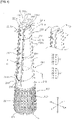
FIG. 8 is a perspective view of a fan according to an embodiment of the present disclosure. -
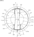
FIG. 9 is a bottom projection view of the fan according to an embodiment of the present disclosure. -
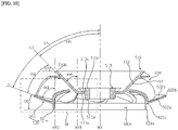
FIG. 10 is a vertical cross-sectional projection view of the fan according to an embodiment of the present disclosure. -
FIG. 11 is an enlarged view of the region M shown inFIG. 10 . -
FIG. 12 is a graph showing air volume performance of the fan according to an embodiment of the present disclosure. -
FIG. 13 is a graph showing noise performance of the fan according to an embodiment of the present disclosure. -
FIG. 14 is a design view of blades according to an embodiment of the present disclosure. -
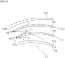
FIG. 15 is a structure view of airfoils of blades according to an embodiment of the present disclosure. -
FIG. 16 is a contour diagram showing optimal design of blades according to an embodiment of the present disclosure. -
FIG. 17 is a perspective view of a fan according to another embodiment of the present disclosure. -
FIG. 18 is an enlarged view of blades according to another embodiment of the present disclosure. -
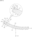
FIG. 19 is a vertical cross-sectional projection view of the blades according to another embodiment of the present disclosure. -
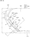
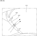
FIG. 20 is a view showing flow on a blade according to another embodiment of the present disclosure. -
FIG. 21 is a graph showing air volume performance of the fan according to another embodiment of the present disclosure. -
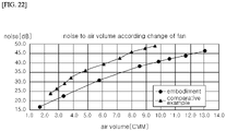
FIG. 22 is a graph showing noise performance of the fan according to an embodiment of the present disclosure. -
FIG. 23 is a perspective view of a fan according to another embodiment of the present disclosure. -
FIG. 24 is a vertical cross-sectional projection view of a fan assembly according to embodiments of the present disclosure. -
FIG. 25 is an enlarged view of a diffuser according to embodiments of the present disclosure. -
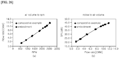
FIG. 26 is a graph showing an effect against an air volume and noise of the diffuser according to an embodiment of the present disclosure. -
FIG. 27 is a graph showing an effect against an air volume and noise of the diffuser according to an embodiment of the present disclosure. - The advantages and features of the present disclosure, and methods of achieving them will be clear by referring to the exemplary embodiments that will be describe hereafter in detail with reference to the accompanying drawings. However, the present disclosure is not limited to the exemplary embodiments described hereafter and may be implemented in various ways, and the exemplary embodiments are provided to complete the description of the present disclosure and let those skilled in the art completely know the scope of the present disclosure and the present disclosure is defined by claims. Like reference numerals indicate like components throughout the specification.
- Hereinafter, the present disclosure will be described with reference to the drawings illustrating blowers according to embodiments of the present disclosure.
- The entire structure of a
blower 1 is described first with reference toFIG. 1. FIG. 1 shows the entire external shape of theblower 1. - The
blower 1 may be referred to as another name such as an air conditioner, an air clean fan, air purifier, etc. in that theblower 1 suctions air and circulates the suctioned air. - The
blower 1 according to an embodiment of the present disclosure may include asuction module 100 that suctions air and ablowing module 200 that discharges suctioned air. - The
blower 1 may have a column shape of which the diameter decreases upward and the entire shape of theblower 1 may be a conical shape or a truncated cone shape. When the cross-section narrows upward, there is an advantage in that the center of gravity lowers and a danger of a fall due to external shock is decreased. However, a shape of which the cross-section does not narrow upward unlike the present embodiment is possible. - The
suction module 100 may be formed such that the diameter gradually decreases upward and theblowing module 200 may also be formed such that the diameter gradually decreases upward. - The
suction module 100 may include abase 110, alower case 120 disposed on thebase 110, and afilter 130 disposed in thelower case 120. - The base 110 may be seated on the ground and can support load of the
blower 1. Thelower case 120 and thefilter 130 may be seated on thebase 110. - The
lower case 120 may have a cylindrical external shape and may form a space in which thefilter 130 is disposed therein Asuction hole 121 that open to the inside of thelower case 120 may be formed at thelower case 120. A plurality of suction holes 121 may be formed along the edge of thelower case 120. - The
filter 130 may have a cylindrical external shape and can filter out foreign substance contained in the air suctioned through thesuction hole 121. - The
blowing module 200 may be separated and disposed into two column shapes extending up and down. Theblower module 200 may include afirst tower 220 and asecond tower 230 that are disposed to be spaced apart from each other. Theblowing module 200 may include atower base 210 connecting thefirst tower 220 and thesecond tower 230 with thesuction module 100. Thetower base 210 may be disposed on thesuction module 100 and may be disposed under thefirst tower 220 and thesecond tower 230. - The
tower base 210 may have a cylindrical external shape and may form a continuous outer circumferential surface with thesuction module 100 by being disposed on thesuction module 100. - The upper surface of the
tower base 210 may be formed to be concave downward and may form a tower baseupper surface 211 extending forward and rearward. Thefirst tower 220 may extend upward from aside 211a of the tower baseupper surface 211 and thesecond tower 230 may extend upward from anotherside 211b of the tower baseupper surface 211. - The
tower base 210 may distribute filtered air supplied from the inside of thesuction module 100 and may provide the distributed air to thefirst tower 220 and thesecond tower 230. - The
tower base 210, thefirst tower 220, and thesecond tower 230 each may be manufactured as a separate part and may be manufactured in an integrated type. Thetower base 210 and thefirst tower 220 may form a continuous external circumferential surface of theblower 1, and thetower base 210 and thesecond tower 230 may form the continuous external circumferential surface of theblower 1. - Unlike the present disclosure, the
first tower 220 and thesecond tower 230 may be assembly directly to thesuction module 100 without thetower base 210 and may be integrally manufactured with thesuction module 100. - The
first tower 220 and thesecond tower 230 may be disposed to be spaced apart from each other and a blowing space S may be formed between thefirst tower 220 and thesecond tower 230. - The blowing space S may be understood as a space being open on the front, the rear, and the top between the
first tower 220 and thesecond tower 230. - The external shape of the
blowing module 200 composed of thefirst tower 220, thesecond tower 230, and the blowing space S may be a truncated cone shape. - Discharge holes 222 and 232 formed at the
first tower 220 and thesecond tower 230, respectively, may discharge air toward the blowing space S. When the discharge holes 222 and 232 need to be discriminated, the discharge hole formed at thefirst tower 220 is referred to as afirst discharge hole 222 and the discharge hole formed at thesecond tower 230 is referred to as asecond discharge hole 232. - The
first tower 220 and thesecond tower 230 may be symmetrically discharged with the blowing space S therebetween. Since thefirst tower 220 and thesecond tower 230 are symmetrically discharged, flow is uniformly distributed in the blowing space S, so it is more advantageous in control of horizontal airflow and ascending airflow. - The
first tower 220 may include afirst tower case 221 forming the external shape of thefirst tower 220 and thesecond tower 230 may include asecond tower case 231 forming the external shape of thesecond tower 230. Thefirst tower case 221 and thesecond tower case 231 may be referred to as upper cases that are disposed on thelower case 120 and have the discharge holes 222 and 232 discharging air, respectively. - The
first discharge hole 222 may be formed at thefirst tower 220 to extend in the up-down direction and thesecond discharge hole 232 may be formed at thesecond tower 230 to extend up and down. - The flow direction of air discharged from the
first tower 220 and thesecond tower 230 may be formed in the front-rear direction. - The width of the blowing space S that is the gap between the
first tower 220 and thesecond tower 230 may be formed to be the same in the up-down direction. However, the upper end width of the blowing space S may be formed to be narrower or wider than the lower end width. - By uniformly forming the width of the blowing space S in the up-down direction, it is possible to uniformly distribute the air, which flows to the front of the blowing space S, in the up-down direction.
- When the width of the upper side and the width of the lower side are different, the flow speed at the wide side may be low and a different of a speed may be generated in the up-down direction. When a flow different of air is generated in the up-down direction, the supply amount of clean air may be changed in accordance with the position in the up-down direction.
- Air discharged from each of the
first discharge hole 222 and thesecond discharge hole 232 may join in the blowing space S and then may be supplied to a user. - Air discharged from the
first discharge hole 222 and air discharged from thesecond discharge hole 232 may join in the blowing space S and then supplied to a user without separately flowing to the user. - The blowing space S may be used as a space in which discharged air is joined and mixed. Indirect airflow is generated in the air around the
blower 1 by the discharged air that is discharged to the blowing space S, so the air around theblower 1 may flow toward the blowing space S. - As the discharged air of the
first discharge hole 222 and the discharged air of thesecond discharge hole 232 join in the blowing space S, straightness of discharged air can be improved. As the discharged air of thefirst discharge hole 222 and the discharged air of thesecond discharge hole 232 join in the blowing space S, the air around thefirst tower 220 and thesecond tower 230 may also be induced to flow forward long the outer circumferential surface of theblowing module 200 by the indirect airflow. - The
first tower case 221 may include: a first towerupper end 221a forming the upper surface of thefirst tower 220; a first towerfront end 221b forming the front surface of thefirst tower 220; a first towerrear end 221c forming the rear surface of thefirst tower 220; a firstouter wall 221d forming the outer circumferential surface of thefirst tower 220, and a firstinner wall 221e forming the inner surface of thefirst tower 220. - The
second tower case 231 may include: a second towerupper end 231a forming the upper surface of thesecond tower 231; a second towerfront end 231b forming the front surface of thesecond tower 231; a second towerrear end 231c forming the rear surface of thesecond tower 231; a secondouter wall 231d forming the outer circumferential surface of thesecond tower 231, and a secondinner wall 231e forming the inner surface of thesecond tower 231. - The first
outer wall 221d and the secondouter wall 231d are formed to be convex outward in the radial direction, so they may form the outer circumferential surfaces of thefirst discharge hole 222 and thesecond discharge hole 232, respectively. - The first
inner wall 221e and the secondinner wall 231e are formed to be convex inward in the radial direction, so they may form the inner circumferential surfaces of thefirst discharge hole 222 and thesecond discharge hole 232, respectively. - The
first discharge hole 222 may be formed in the firstinner wall 221e to extend in the up-down direction and may be formed to be open inward in the radial direction. Thesecond discharge hole 232 may be formed in the secondinner wall 231e to extend in the up-down direction and may be formed to be open inward in the radial direction. - The
first discharge hole 222 may be formed at a position closer to the first towerrear end 221c of the first towerfront end 221b. Thesecond discharge hole 232 may be formed at a position closer to the second towerrear end 231c of the second towerfront end 231b. - A
first board slot 223 that afirst airflow shifter 320 that will be described below passes through may be formed in the firstinner wall 221e to extend in the up-down direction. Asecond board slot 233 that asecond airflow shifter 330 that will be described below passes through may be formed in the secondinner wall 231e to extend in the up-down direction. Thefirst board slot 223 and thesecond board slot 233 may be formed to be open inward in the radial direction. - The
first board slot 223 may be formed at a position closer to the first towerfront end 221b of the first towerrear end 221c. Thesecond board slot 233 may be formed at a position closer to the second towerfront end 231b of the second towerrear end 231c. Thefirst board slot 223 and thesecond board slot 233 may be formed to face each other. - Hereafter, the internal structure of the
blower 1 is described with reference toFIGS. 2 and3 .FIG. 2 is a cross-sectional projection view cutting theblower 1 along line P-P' shown inFIG. 1 andFIG. 3 is a cross-sectional projection view cutting theblower 1 along line Q-Q' shown inFIG. 1 . - Referring to
FIG. 2 , adriving module 150 that rotates theblower 1 in the circumferential direction may be disposed on thebase 110. A drivingspace 100S in which thedriving module 150 is disposed may be formed on thebase 110. - The
filter 130 may be disposed on the drivingspace 100S. The external shape of thefilter 130 may be a cylindrical shape and acylindrical filter hole 131 may be formed in thefilter 130. - Air suctioned inside through the
suction hole 121 may flow to thefilter hole 131 through thefilter 130. - A
suction grill 140 that air, which passes through thefilter 130 and flows upward, passes through may be disposed on thefilter 130. Thesuction grill 140 may be disposed between afan assembly 400 that will be described below and thefilter 130. Thesuction grill 140 may prevent a user's hand from being put into thefan assembly 400 when thelower case 210 is removed and thefilter 130 is separated from theblower 1. - The
fan assembly 400 may be disposed on thefilter 130 and may generate a suction force for air outside theblower 1. - By driving of the
fan assembly 400, the air outside theblower 1 may sequentially pass through thesuction hole 121 and thefilter hole 131 and flow to thefirst tower 220 and thesecond tower 230. - A pressurizing space 400s in which the
fan assembly 400 is disposed may be formed between thefilter 130 and theblowing module 200. - A
first distribution space 220s in which air passing through the pressurizing space 400s flows upward may be formed in thefirst tower 220, and asecond distribution space 230s in which air passing through the pressurizing space 400s flows upward may be formed in thesecond tower 230. Thetower base 210 may distribute air passing through the pressurizing space 400s to afirst distribution space 220s and asecond distribution space 230s. Thetower base 210 may be a channel connecting the first andsecond towers fan assembly 400. - The
first distribution space 220s may be formed between the firstouter wall 221d and the firstinner wall 221e. Thesecond distribution space 230s may be formed between the secondouter wall 231d and the secondinner wall 231e. - The
first tower 220 may include afirst flow guide 224 that guides a flow direction of air in thefirst distribution space 220s. A plurality of first flow guides 224 may be disposed to be spaced part from each other up and down. - The
first flow guide 224 may be formed to protrude toward the first towerfront end 221b from the first towerrear end 221c. Thefirst flow guide 224 may be spaced apart from the first towerfront end 221b in the front-read direction. Thefirst flow guide 224 may extend to be inclined downward toward the front. A first guidefront end 224a forming the front surface of thefirst flow guide 224 may be positioned lower than a first guiderear end 224b forming the rear surface of thefirst flow guide 224. The downwardly inclined angles of first flow guides disposed at the upper portion of a plurality of first flow guides 224 may be smaller. - The
second tower 230 may include asecond flow guide 234 that guides a flow direction of air in thesecond distribution space 230s. A plurality of second flow guides 234 may be disposed to be spaced part from each other up and down. - The
second flow guide 234 may be formed to protrude toward the second towerfront end 231b from the second towerrear end 231c. Thesecond flow guide 234 may be spaced apart from the second towerfront end 231b in the front-read direction. Thesecond flow guide 234 may extend to be inclined downward toward the front. A second guidefront end 234a forming the front surface of thesecond flow guide 234 may be positioned lower than a second guiderear end 234b forming the rear surface of thesecond flow guide 234. The downwardly inclined angles of second flow guides disposed at the upper portion of a plurality of second flow guides 234 may be smaller. - The
first flow guide 224 may guide air discharged from thefan assembly 400 to flow toward thefirst discharge hole 222. Thesecond flow guide 234 may guide air discharged from thefan assembly 400 to flow toward thesecond discharge hole 232. - Referring to
FIG. 3 , thefan assembly 400 may include: afan motor 410 that generates power; amotor housing 430 in which thefan motor 410 is accommodated; afan 500 that is rotated by receiving power from thefan motor 410; and adiffuser 440 that guides the flow direction of air pressurized by thefan 500. - The
fan motor 410 may be disposed on thefan 500 and may be connected with thefan 500 through amotor shaft 411 extending downward from thefan motor 410. - The
motor housing 430 may include afirst motor housing 431 covering the upper portion of thefan motor 410 and asecond motor housing 432 covering the lower portion of thefan motor 410. - The
first discharge hole 222 may extend upward from aside 211a of the tower baseupper surface 211. A first discharge holelower end 222d may be formed at theside 211a of the tower baseupper surface 211. - The
first discharge hole 222 may be formed to be spaced under the first towerupper end 221a. A first discharge holeupper end 222c may be formed to be spaced under the first towerupper end 221a. - The
first discharge hole 222 may extend to be inclined in the up-down direction. Thefirst discharge hole 222 may extend to be inclined forward toward the upper portion. Thefirst discharge hole 222 may extend to be inclined rearward with respect to an up-down axis Z extending in the up-down direction. - The first discharge hole
front end 222a and the first discharge holerear end 222b may extend to be inclined in the up-down direction and may extend in parallel with each other. The first discharge holefront end 222a and the first discharge holerear end 222b may extend to be inclined rearward with respect to the up-down axis Z extending in the up-down direction. - The
first tower 220 may include afirst discharge guide 225 that guides air in thefirst distribution space 220s to thefirst discharge hole 222. - The
first tower 220 may be symmetric to thesecond tower 230 with the blowing space S therebetween and may have the same shape and structure as thesecond tower 230. The above description of thefirst tower 220 may be applied to thesecond tower 230 in the same way. - Hereafter, an air discharge structure of the
blower 1 for inducing Coanda effect is described with reference toFIGS. 4 and5 .FIG. 4 is a projection view showing theblower 1 in the right downward direction from above andFIG. 5 is a projection view showing theblower 1 cut along line R-R' shown inFIG. 1 in the upward direction. - Referring to
FIG. 4 , gaps D0, D1, and D2 between the firstinner wall 221e and the secondrear wall 231e may become smaller as they are close to the center of the blowing space S. - The first
inner wall 221 e and the secondinner wall 231e may be formed to be convex inward in the radial direction, and the shortest distance D0 may be formed between the apexes of the firstinner wall 221e and the secondinner wall 231e. The shortest distance D0 may be formed at the center of the blowing space S. - The
first discharge hole 222 may be formed behind the position where the shortest distance D0 is formed. Thesecond discharge hole 232 may be formed behind the position where the shortest distance D0 is formed. - The first tower
front end 221b and the second towerfront end 231b may be spaced apart from each other by a first gap D1. The first towerrear end 221c and the second towerrear end 231c may be spaced apart from each other by a second gap D2. - The first gap D1 and the second gap D2 may be the same. The first gap D1 may be larger than the shortest distance D0 and the second gap D2 may be larger than the shortest distance D0.
- The gap between the first
inner wall 221e and the secondinner wall 231e may decrease from the rear ends 221c and 231c to the position where the shortest distance D0 is formed and may increase from the position where the shortest distance D0 is formed to the front ends 221b and 231b. - The first tower
front end 221b and the second towerfront end 231b may be formed to be inclined with respect to a front-rear axis X. - Tangent lines extending from the first tower
front end 221b and the second towerfront end 231b each may have a predetermined inclination angle A with respect to the front-rear axis X. - A portion of the air discharged forward through the blowing space S may flow with the inclination angle A with respect to the front-rear axis X.
- By the structure described above, a diffusion angle of air discharged forward through the blowing space S may increase.
- The
first airflow shifter 320 that will be described below may be inserted in the first board slit 223 when air is discharged forward from the blowing space S. - The
second airflow shifter 330 that will be described below may be inserted in the second board slit 233 when air is discharged forward from the blowing space S. - Referring to
FIG. 5 , the flow direction of the air discharged toward the blowing space S may be guided by thefirst discharge guide 225 and thesecond discharge guide 235. - The
first discharge guide 225 may include a firstinner guide 225a connected with the firstinner wall 221e and a firstouter guide 225b connected with the firstouter wall 221d. - The first
inner guide 225a may be manufactured integrally with the firstinner wall 221e, but may be manufactured as a separate part. - The first
outer guide 225b may be manufactured integrally with the firstouter wall 221d, but may be manufactured as a separate part. - The first
inner guide 225a may be formed to protrude toward thefirst distribution space 220s from the firstinner wall 221e. - The first
outer guide 225b may be formed to protrude toward thefirst distribution space 220s from the firstouter wall 221d. The firstouter guide 225b may be formed to be spaced outside the firstinner guide 225a, and may form thefirst discharge hole 222 between the firstouter guide 225b and the firstinner guide 225a. - The radius of curvature of the first
inner guide 225a may be formed to be smaller than the radius of curvature of the firstouter guide 225b. - Air of the
first distribution space 220s may flow between the firstinner guide 225a and the firstouter guide 225b and flow to the blowing space S through thefirst discharge hole 222. - The
second discharge guide 235 may include a secondinner guide 235a connected with the secondinner wall 231e and a secondouter guide 235b connected with the secondouter wall 231d. - The second
inner guide 235a may be manufactured integrally with the secondinner wall 231e, but may be manufactured as a separate part. - The second
outer guide 235b may be manufactured integrally with the secondouter wall 231d, but may be manufactured as a separate part. - The second
inner guide 235a may be formed to protrude toward thesecond distribution space 230s from the secondinner wall 231e. - The second
outer guide 235b may be formed to protrude toward thesecond distribution space 230s from the secondouter wall 231d. The secondouter guide 235b may be formed to be spaced outside the secondinner guide 235a, and may form thesecond discharge hole 232 between the secondouter guide 235b and the secondinner guide 235a. - The radius of curvature of the second
inner guide 235a may be formed to be smaller than the radius of curvature of the secondouter guide 235b. - Air of the
second distribution space 230s may flow between the secondinner guide 235a and the secondouter guide 235b and flow to the blowing space S through thesecond discharge hole 232. - Widths w1, w2, and w3 of the
first discharge hole 222 may be formed to gradually decrease toward the outlet from the inlet of thefirst discharge guide 225 and then increase. - The size of the inlet width w1 of the
first discharge guide 225 may be larger than the outlet width w3 of thefirst discharge guide 225. - The inlet width w1 may be defined as the gap between an outer end of the first
inner guide 225a and an outer end of the firstouter guide 225b. The outlet width w3 may be defined as the gap between the first discharge holefront end 222a that is an inner end of the firstinner guide 225a and the first discharge holerear end 222b that is an inner end of the firstouter guide 225b. - The sizes of the inlet width w1 and the outlet width w3 may be larger than the size of a shortest width w2 of the
first discharge hole 222. - The shortest width w2 may be defined as the shortest distance between the first discharge hole
rear end 222b and the firstinner guide 225a. - The widths of the
first discharge hole 222 may gradually decrease from the inlet of thefirst discharge guide 225 to the position where the shortest width w2 is formed and may gradually increase from the position where the shortest width w2 is formed to the outlet of thefirst discharge guide 225. - The
second discharge guide 235, similar to thefirst discharge guide 225, may also have a second discharge holefront end 232a and a second discharge holerear end 232b and may have distribution of width the same as thefirst discharge guide 225. - Hereafter, an air direction change by an
airflow shifter 300 is described with reference toFIGS. 6 and7 .FIG. 6 is a view showing the case in which theairflow shifter 300 protrudes to the blowing space S and theblower 1 forms ascending airflow andFIG. 7 is a view showing the operation principle of theairflow shifter 300. - Referring to
Fig. 6 , theairflow shifter 300 may protrude toward the blowing space S and may change the flow of air, which is discharged forward through the blowing space S, into ascending air. - The
airflow shifter 300 may include afirst airflow shifter 320 disposed in thefirst tower case 221 and asecond airflow shifter 330 disposed in thesecond tower case 231. - The
first airflow shifter 320 and thesecond airflow shifter 330 may block the front of the blowing space S by protruding from the blowing space S from thefirst tower 220 and thesecond tower 230, respectively. - When the
first airflow shifter 320 and thesecond airflow shifter 330 protrude and block the front of the blowing space S, air discharged through thefirst discharge hole 222 and thesecond discharge hole 232 is blocked by theairflow shifter 330, so the air may flow upward Z. - When the
first discharge hole 222 and thesecond discharge hole 232 are inserted into thefirst tower 220 and thesecond tower 230, respectively, and open the front of the blowing space S, air discharged through thefirst discharge hole 222 and thesecond discharge hole 232 may flow forward X through the blowing space S. - Referring to
FIG. 7 , theairflow shifters board 321 protruding toward the blowing space; amotor 322 providing a driving force to theboard 321; aboard guide 323 guiding a movement direction of theboard 321; and acover 324 supporting themotor 322 and theboard guide 323. - The
first airflow shifter 320 is exemplified in the following description, but the following description of thefirst airflow shifter 320 may also be applied to thesecond airflow shifter 330 in the same way. - The
board 321, as shown inFIGS. 4 and5 , may be inserted in the first board slit 223. Theboard 321 may protrude to the blowing space S through the first board slit 223 when themotor 322 is driven. Theboard 321 may have an arch shape of which the shape of a transverse cross-section is an arc shape. Theboard 321 may move in the circumferential direction and protrude to the blowing space S when themotor 322 is driven. - The
motor 322 may be connected with apinion gear 322a and may rotate thepinion gear 322a. Themotor 322 may rotate thepinion gear 322a clockwise and counterclockwise. - The
board guide 323 may have a plate shape extending up and down. Theboard guide 323 may include aguide slit 323a extending to be inclined up and down and arack 323b formed to protrude toward thepinion gear 322a. - The
rack 323b may be engaged with thepinion gear 322a. When themotor 322 is driven and thepinion gear 322a is rotated, therack 323b engaged with thepinion gear 322a may be moved up and down. - A
guide protrusion 321a formed at theboard 321 to protrude toward theboard guide 323 may be inserted in theguide slit 323a. - When the
board guide 323 is moved up and down in accordance with up/down movement of therack 323b, theguide protrusion 321a may be moved by force from theguide slit 323a. As theboard guide 323 is moved up and down, theguide protrusion 321a may be diagonally moved in theguide slit 323a. - When the
rack 323b is moved up, theguide protrusion 321a may be moved along theguide slit 323a and may be positioned at the lowermost end of theguide slit 323a. When theguide protrusion 321a is positioned at the lowermost end of theguide slit 323a, theboard 321, as shown inFIGS. 4 and5 , may be completely hidden in thefirst tower 220. When therack 323b is moved up, theguide slit 323a is also moved up, so theguide protrusion 321a may be moved in the circumferential direction o the same horizontal surface along theguide slit 323a. - When the
rack 323b is moved down, theguide protrusion 321a may be moved along theguide slit 323a and may be positioned at the uppermost end of theguide slit 323a. When theguide protrusion 321a is positioned at the uppermost end of theguide slit 323a, theboard 321, as shown inFIG. 6 , may protrude toward the blowing space S from thefirst tower 220. When therack 323b is moved down, theguide slit 323a is also moved down, so theguide protrusion 321a may be moved in the circumferential direction o the same horizontal surface along theguide slit 323a. - The
cover 324 may include: afirst cover 324a disposed outside theboard guide 323; asecond cover 324b disposed inside theboard guide 323 and being in close contact with the firstinner surface 221e; amotor support plate 324c extending upward from thefirst cover 324a and connected with themotor 322; and astopper 324b restricting up/down movement of theboard guide 323. - The
first cover 324a may cover the outer side of theboard guide 323 and thesecond cover 324b may cover the inner side of theboard guide 323. Thefirst cover 324a may separate the space in which theboard guide 323 is disposed from thefirst distribution space 220s. Thesecond cover 324b may prevent theboard guide 323 from coming in contact with the firstinner wall 221e. - The
motor support plate 324c may extend upward from thefirst cover 324a and support load of themotor 322. - The
stopper 324d may be formed to protrude toward theboard guide 323 from thefirst cover 324a. A locking protrusion (not shown) that is locked to thestopper 324d in accordance with up/down movement may be formed on one surface of theboard guide 323. When theboard guide 323 is moved up and down, the locking protrusion (not shown) is locked to thestopper 324d, so the up/down movement of theboard guide 323 may be restricted. - Hereafter, the
fan 500 according to an embodiment of the present disclosure is described with reference toFIGS. 8 and9 .FIG. 8 is a perspective view of thefan 500 according to an embodiment of the present disclosure andFIG. 9 is a view showing thefan 500 according to an embodiment of the present disclosure upward from under. - A mixed-flow fan may be used as the
fan 500. However, the kind of thefan 500 is not limited to a mixed-flow fan and other kinds of fans may be used. - The
fan 500 may include ahub 510 coupled to thefan 410, ashroud 520 disposed to be spaced under thehub 510, and a plurality ofblades 530 connecting theshroud 520 and thehub 510. - A
motor shaft 411 of thefan motor 410 is coupled to the center of thehub 510, and when thefan motor 410 is operated, thehub 510 may be rotated with themotor shaft 411. - When the
fan 500 is rotated, air may flow toward thehub 510 from theshroud 520 of thefan 500. - The
hub 510 may be formed in a bowl shape that is concave downward and thefan motor 410 may be disposed on thehub 510. - The
hub 510 may include afirst hub surface 511 disposed on theshroud 520 to face theshroud 520. - The
first hub surface 511 may be a conical shape protruding downward, may have a transverse cross-section of which the shape is a circular shape, and may be a shape in which the diameter of a cross-section increases toward the upper end. - The
shroud 520 may be disposed to be space under thehub 510 and may be disposed to surround thehub 510. - At least a portion of the
hub 510 may be inserted in the center portion of theshroud 520. The diameter of thehub 510 may be smaller than the diameter of theshroud 520. - The
shroud 520 may include arim portion 521 extending in the circumferential direction and a supportingportion 522 extending to be inclined upward from therim portion 521. Therim portion 521 and the supportingportion 522 may be integrally manufactured through injection molding. - The
rim portion 510 may be formed in an annular shape. Air may be suctioned into therim portion 510 - The
rim portion 521 may be formed such that the up-down height is longer than the thickness. Therim portion 521 may vertically extend up and down. - The extension length of the
rim portion 511 in the up-down direction and the upward inclined extension length of the supportingportion 522 may have a ratio of 1:3. - The
blades 530 may connect thehub 510 and theshroud 520 that are disposed to be spaced apart from each other. The upper ends of theblades 530 may be coupled to thehub 510 and the lower ends may be coupled to theshroud 520. - The
blade 530 may include: apositive pressure surface 531 disposed toward thehub 510; anegative pressure surface 532 disposed toward theshroud 520; aroot portion 535 connected with thehub 510; atip portion 536 connected with theshroud 520; aleading edge 533 connecting one end of theroot portion 535 and one end of thetip portion 536; and a trailingedge 534 connecting another end of theroot portion 535 and another end of thetip portion 536. - The
root portion 535 and thetip portion 536 may be formed an airfoils. - The
leading edge 533 may be a front end that first comes in contact with air when thehub 510 is rotated, and the trailingedge 534 may be a rear end that latest comes in contact with air when thehub 510 is rotated. - The
leading edge 533 may be disposed toward the rotation center of thefan 500 and the trailingedge 534 may be disposed toward the outside in the radial direction of thefan 500. - The
root portion 535 may be in contact with thefirst hub surface 511 of thehub 510 in an inclined type. - The
top portion 536 may be in contact with the supporting portion 552 of theshroud 520 in an inclined type. - The inclined extension length of the
first hub surface 511 may be smaller than the length of theroot portion 535. Theroot portion 535 may be connected to be inclined with respect to the first hub surface 1110. - The inclined extension length of the supporting
portion 522 may be smaller than the length of thetip portion 536. Thetip portion 536 may be connected to be inclined with respect to the supportingportion 522. - A plurality of
blades 530 may be disposed to be spaced in the circumferential direction. Theleading edge 533 of each of the plurality ofblades 530 may be disposed to at least partially face the trailingedge 534 ofadjacent blades 530. Accordingly, when thefan 500 is seen from under, as inFIG. 9 , theleading edge 533 of any oneblade 530 may be seen like overlapping the trailingedge 534 of anadjacent blade 530. - Hereafter, the position relationship of the
hub 510 and theshroud 520 is described with reference toFIGS. 10 and11 .FIG. 10 is a cross-sectional projection view cutting thefan 500 in the longitudinal direction andFIG. 11 is a view enlarging the region M shown inFIG. 10 . - The
hub 510 may include asecond hub surface 512 disposed toward thefan motor 410 and ashaft coupling portion 513 to which themotor 411 is coupled. - The
first hub surface 511 may be disposed toward the lower side and thesecond hub surface 512 may be disposed toward the upper side. Thefan motor 410 may be inserted in thesecond hub surface 512 and connected with thehub 510. - The
motor shaft 411 of thefan motor 410 may be coupled to theshaft coupling portion 513. Theshaft coupling portion 513 may be disposed to pass through thehub 510 in the up-down direction. The rotation center of thefan 500 may be formed inside theshaft coupling portion 513. Theshaft coupling portion 513 may be formed integrally with thefirst hub surface 511 and thesecond hub surface 512. - The
shaft coupling portion 513 may be formed to protrude downward from thefirst hub surface 511 and may be formed to protrude upward from thesecond hub surface 512. - The
shaft coupling portion 513 may form a hublower end 510a by protruding downward. Theshaft coupling portion 513 may form ahub protrusion end 510c by protruding upward. Theshaft coupling portion 513 may form a hub middle portion by being connected with thefirst hub surface 511. - The
first hub surface 511 and thesecond hub surface 512 may extend to be inclined outward in the radial direction and may form a hubupper end 510b. - The
hub 510 may extend in a straight line shape to be inclined outward in the radial direction. The inclined extension direction of thehub 510 is defined as L1 and the inclined angle of thehub 510 is defined as a hub inclination angle θ1. The diameter of thehub 510 may increase toward the outside in the radial direction, and the internal space of thehub 510 may expand upward. The hub inclination angle θ1 may be formed in the range of 45 degrees to 60 degrees. - The
rim portion 521 may extend in the up-down direction and may form afan suction hole 500s therein. Therim portion 521 may include a rim portionlower end 520a constituting the lower portion of thefan suction hole 500s and a rim portion upper end 520d connected with the supportingportion 522. - The supporting
portion 522 may extend to be inclined outward in the radial direction from the rim portionupper end 520c and may form ashroud edge 520b at the outermost side in the radial direction. The rim portionupper end 520c may be the boundary of therim portion 521 and the supportingportion 522. - The
shroud 522 may include afirst shroud surface 522a disposed toward the lower side and asecond shroud surface 522b disposed toward the upper side. Thefirst shroud surface 522a may be formed to face thesuction grill 140 and thesecond shroud surface 522b may be formed to face thefirst hub surface 511. Therim portion 521 may protrude downward from thefirst shroud surface 522a. Theblades 530 may be coupled to thesecond shroud surface 522b. - The hub
upper end 510b may be disposed inside further than therim portion 521 in the radial direction. It is possible to sufficiently secure the length of theblades 530 and increase an air volume by sufficiently spacing the hubupper end 510b and theshroud edge 520b. - At least a portion of the
diffuser 440 that will be described below may be disposed between the hubupper end 510b and theshroud edge 520b. The height at which at least a portion of thediffuser 440 is disposed may be formed between the hubupper end 510b and theshroud edge 520b. - The
shroud 520 may extend in a straight line shape to be inclined outward in the radial direction. The inclined extension direction of theshroud 520 is defined as L2 and the inclined angle of theshroud 520 is defined as a shroud inclination angle θ2. The diameter of theshroud 520 may increase toward the outside in the radial direction, and the internal space of theshroud 520 may expand upward. The shroud inclination angle θ2 may be formed in the range of 35 degrees to 50 degrees. - The hub inclination angle θ1 and the shroud inclination angle θ2 may be formed to be different, and a flow passage through which air flowing inside through the
fan suction hole 500s may be formed between thehub 510 and theshroud 520. The contained angle between thehub 510 and theshroud 520 is defined as an expansion angle θ3. A flow passage having the size of the expansion angle θ3 may be formed between thehub 510 and theshroud 520. - The hub inclination angle θ1 may be formed to be larger than the shroud inclination angle θ2. Since the hub inclination angle θ1 is formed to be larger than the shroud inclination angle θ2, it is possible to increase the size of the expansion angle θ3 and it is possible to reduce friction resistance acting in the air passing through the
fan suction hole 500s. - The
hub 510 may have anouter surface 511 extending to be inclined at a first angle θ8 with respect to themotor shaft 411. Theouter surface 511 may be thefirst hub surface 511. - The
shroud 520 may extend to be inclined at a second angle θ9 that is larger than the first angle θ8 with respect to themotor shaft 411. - The inner surface of the supporting
portion 522 of theshroud 520 may face theouter surface 511 of thehub 510 with theblades 530 therebetween. - The
motor shaft 411 may rotate thehub 510 and theblades 530 by being inserted in theshaft coupling portion 513 and may form a rotation axis MX of thefan 500. - The hub
upper end 510b may form a hub area HA by being spaced apart from the rotation axis MX by a predetermined angle. Theshroud edge 520b may form a shroud area SA by being spaced apart from the rotation axis MX by a predetermined angle. - The size of the shroud area SA may be larger than the size of the hub area HA.
- The
hub 510 may extend to be inclined at the first angle θ8 with respect to a first axis MX1 that is parallel with the rotation axis MX and passes through theshaft coupling portion 513. - The
shroud 520 may extend to be inclined at the second angle θ9 with respect to a second axis MX2 that is parallel with the rotation axis MX and passes through therim portion 521. - The size of the first angle θ8 may be smaller than the second angle θ9.
- The sum of the hub inclination angle θ1 and the first angle θ8 may be 90 degrees, and the sum of the shroud angle θ2 and the second angle θ9 may be 90 degrees.
- The height of the rim portion
upper end 520c is defined as H1, the height of the hublower end 510a is defined as H2, the height of theshroud edge 520b is defined as H3, the height of the hubmiddle portion 510d is defined as H4, and the height of thehub protrusion end 510c is defined as H5. - The
fan 500 may be formed in a shape satisfying the relationship of H5>H4>H3>H2>H1. In detail, the hublower end 510a may be formed higher than the rim portionupper end 520c, theshroud edge 520b may be formed higher than the hublower end 510a, the hubmiddle portion 510d may be formed higher than theshroud edge 520b, and thehub protrusion end 510c may be formed higher than the hubmiddle portion 510d. - The height H3 of the
shroud edge 520b may be formed between the height H2 of the hublower end 510a and the height H5 of thehub protrusion end 510c. The height H3 of theshroud edge 520b may be formed between the height H2 of the hublower end 510a and the height H4 of the hubmiddle portion 510d. - The
first hub surface 511 may include afirst guide surface 511a connected with theshaft coupling portion 513 and asecond guide surface 511b extending to be inclined upward from thefirst guide surface 511a. Thefirst guide surface 511a may horizontally extend from theshaft coupling portion 513 and thesecond guide surface 511b may extend upward from the outer end of thefirst guide surface 511a. - Due to the structure described above, air flowing inside through the
fan suction hole 500s and reaching thefirst guide surface 511a may flow upward along thesecond guide surface 511b without going out to the upper side of theshroud edge 520b. Air flowing inside through thefan suction hole 500s may be guided to flow in the range of the expansion angle θ3 without going to the outside of thefan 500 through theshroud 520b, so a flow loss can be reduced. - Hereafter, an operation effect on air volume and noise according to the shroud inclination angle θ2 is described with reference to
FIGS. 12 and13 .FIG. 12 shows an air volume according to the shroud inclination angle θ2 in a graph andFIG. 13 shows noise according to the shroud inclination angle θ2 in a graph.[Table 1] Shroud angle (F2) RPM (@10CMM) dB(@10CMM) sharpness(@ 10CM M) 20 2250 41.9 1.17 30 2245 42.3 1.07 35 2231 43.3 1.06 - Table 1 shows experiment results of the number of revolutions, noise, and sharpness of the
fan 500 when an air volume is 10CMM. Referring toFIG. 13 , it can be seen that as the RPM increases, the air volume increases when the shroud inclination angle θ2 is 20 degrees, 30 degrees, and 35 degrees. - Referring to
FIG. 14 , it can be seen that as the air volume increases, the noise also increases when the shroud inclination angle θ2 is 20 degrees, 30 degrees, and 35 degrees. However, it can be seen that as the shroud inclination angle θ2 decreases, noise is large, and as the shroud inclination angle θ2 increases, noise decreases. - The expansion angle θ3 may be set in the range of 11 degrees and 26 degrees in consideration of noise and an air volume, and preferably, the expansion angle θ3 may be 12 degrees.
- Hereafter, the
blades 530 according to an embodiment of the present disclosure is described with reference toFIGS. 14 and15 .FIG. 14 shows oneblade 530 andFIG. 15 shows a plurality ofairfoils blade 530. - A great number of airfoils may be formed from the
root portion 535 to thetip portion 536 of theblade 530, and theblade 530 may be understood as a group of a plurality of airfoils. The airfoil may also be understood as a cross-sectional shape of theblade 530. Theroot portion 535 and thetip portion 536 may be included in a plurality of airfoils. - In the plurality of airfoils, any one airfoil between the
root portion 535 and thetip portion 536 may be defined asreference airfoils - The
reference airfoils root portion 535 and thetip portion 536 makes a constant reference ratio. - The distance from the
reference airfoils root portion 535 may be a first distance and the distance from thereference airfoils tip portion 536 may be a second distance. The ratio of the first distance and the second distance may be 1:2, and thereference airfoil 537 in this case may be defined as afirst reference airfoil 537. The ratio of the first distance and the second distance may be 2;1, and thereference airfoil 538 in this case may be defined as asecond reference airfoil 538. - The
leading edge 533 may be formed to be curved along the plurality ofairfoils - The
root portion 535 may form afirst intersection point 535a with theleading edge 533 and thetip portion 536 may form asecond intersection point 536a with theleading edge 533. Theleading edge 533 may extend to be curved from thefirst intersection point 535a to thesecond intersection point 536a. - A virtual leading line L3 connecting the
first intersection point 535a to thesecond intersection point 536a may be formed. Theleading edge 533 may be formed to be spaced apart from the leading line L3. - The
first reference airfoil 537 may form athird intersection point 537a with theleading edge 533 and thesecond reference airfoil 538 may form afourth intersection point 538a with theleading edge 533. - The
third intersection point 537a may be understood as a point at which a first mean camber line CL1 of thefirst reference airfoil 537 crosses theleading edge 533. - The
fourth intersection point 538a may be understood as a point at which a second mean camber line CL2 of thesecond reference airfoil 538 crosses theleading edge 533. - A
third intersection point 537a and thefourth intersection point 538a may be formed to be spaced apart from the leading line L3. - The traces of the
intersection points fan 500 may form a circle around themotor shaft 411. The traces of theintersection points leading edge 533. - The
third intersection point 537a may form a circular first trace C1 by rotation of thefan 500. Thefourth intersection point 538a may form a circular second trace C2 by rotation of thefan 500. - The
leading edge 533 of theblade 530 may be designed on the basis of inlet angles θ4 and θ5 of thereference airfoils - The first inlet angle θ4 of the
first reference airfoil 537 may mean an angle made by an extension line of the first mean camber line CL1 and the first trace C1. - The tangential line of the first mean camber line CL1 at the
third intersection point 537a is defined as a first tangential line T1 and the tangential line of the first trace C1 at thethird intersection point 537a is defined as a first base line B1. - The first inlet angle θ4 of the
first reference airfoil 537 may be understood as the angle between the first tangential line T1 and the first base line B1. - The second inlet angle θ4 of the
second reference airfoil 538 may mean an angle made by an extension line of the second mean camber line CL2 and the second trace C2. - The tangential line of the second mean camber line CL2 at the
fourth intersection point 538a is defined as a second tangential line T2 and the tangential line of the second trace C2 at thefourth intersection point 538a is defined as a second base line B2. - The second inlet angle θ5 of the
second reference airfoil 538 may be understood as the angle between the second tangential line T2 and the second base line B2. - The
blade 530 may be formed such that the inlet angle can be varied in a span direction. The inlet angle may be continuously varied in the span direction. The span direction may mean an extension direction of theleading edge 533 formed to be curved toward thesecond intersection point 538a from thefirst intersection point 537a. - The inlet angle of the
blade 530 in the span direction may be changed to implement an appropriate airfoil at different positions of theleading edge 533 in accordance with the characteristics of flow at the positions. AS the inlet angle of theblade 530 in the span direction is changed, the shape of theleading edge 533 may be formed to be curved. - A virtual blade extending such that the leading edge has the same inlet angle in the span direction may be defined as a "first comparative blade". The inlet angle of the first comparative blade is the same in all airfoils.
- The inlet angles θ4 and θ5 of the
reference airfoils blade 530 according to an embodiment of the present disclosure may be larger of the inlet angle of the first comparative blade. - A blade in which the leading edge straightly extends from the rood portion to the tip portion may be defined as a "second comparative blade". In the second comparative blade, the leading line L3 defined in the description of the present disclosure may coincide with the
leading edge 533. - The first comparative blade and the second comparative blade may have a comparative root portion and a comparative tip portion that are the same as the
root portion 535 and thetip portion 536 of the present disclosure. - Comparing the inlet angles at the same position of the
blade 530 of the present disclosure and the comparative blade, the inlet angle of theblade 530 of the present disclosure may be larger than the inlet angle of the comparative blade.[Table 2] Items Inlet angle of airfoil (°) Noise Resultant value (dB@10CMM) Comparative blade 24.5 47.2(-) Blade of disclosure 17.5<θ≤20.5 47.5(↑0.3) 20.5<θ≤23.5 47.3(↑0.1) 23.5<θ≤26.5 47.2(-) 26.5<θ≤29.5 47.0(↓0.2) 29.5<θ≤32.5 46.7(↓0.5) - Table 2 is a table showing a noise resultant value according to the inlet angle of an airfoil. The inlet angle of an airfoil that is a comparison target mean the inlet angle of an airfoil positioned at a 2/3 position of the root portion and the tip portion (the position of the
second reference airfoil 538 of the present disclosure). - The inlet angle of the airfoil of the comparative blade may be 24.5°, and a noise resultant value may be measured by setting the inlet angle of the airfoil of the comparative blade as a comparison group and the inlet angle θ5 of the
second reference airfoil 538 as an experiment group. - The noise resultant value is a value obtained by measuring decibel dB when an air volume is 10CMM.
- According to Table 2, the inlet angle θ5 of the
second reference airfoil 538 exceeds 29.5° and is 32.5° or less, the noise resultant value may be lowest as 46.7dB. - The inlet angle θ5 of the
second reference airfoil 538 may have a value that exceeds 29.5° and is 32.5° or less. - When the inlet angle θ5 of the
second reference airfoil 538 has a larger value, noise has tendency of decreasing. - However, other factors such as the area, the thickness, the length, etc. of the blade complexly influence noise, so when the inlet angle θ5 of the
second reference airfoil 538 exceeds 33°, noise has tendency of increasing again. - The
first reference airfoil 537 may be an airfoil at a 1/3 position of theroot portion 535 and thetip portion 536, and thesecond reference airfoil 538 may be an airfoil at a 2/3 position of theroot portion 535 and thetip portion 536. - The
blade 530 may be designed on the basis of the first inlet angle θ4 of thefirst reference airfoil 537 and the second inlet angle θ5 of thesecond reference airfoil 538. - In the
blade 530, an optimal inlet angle may be primarily selected on the basis of the second inlet angle θ5 and then the first inlet angle θ4 may be selected through a 2-factor 2-level experiment. - It is possible to calculate the second inlet angle θ5 at which noise least generated by performing an experiment on the second inlet angle θ5 of the
second reference airfoil 538 and it is possible to perform an optimal experiment while changing the first inlet angle θ4 with the second inlet angle θ5 obtained. - The optimal experiment may be performed on the decibel dB measured when the air volume is 3CMM.
- In order to calculate optimal first inlet angle θ4 and second inlet angle θ5, an experiment may be performed on the basis of the case in which the comparative target inlet angle at a 1/3 position of the root portion and the tip portion of the comparative blade is around 21.5° and the comparative target inlet angle at a 2/3 position of the root portion and the tip portion is around 24.5°.
- It is possible to calculate an optimal value while changing the second inlet angle θ5 on the basis of the case in which the comparative target inlet angle at a 2/3 position of the root portion and the tip portion is 24.5°. The optimal second inlet angle θ5 primarily selected may exceed 29.5° and may be 32. 5° or less, depending on experiments.
- Thereafter, in order to select first inlet angle θ4 and second inlet angle θ5, an experiment may be performed on the basis 21.5° that is the comparative target inlet angle at a 1/3 position of the root portion and the tip portion of the comparative blade and 32.5° that is one of the selected optimal second inlet angles θ5.
- In detail, it is possible to measure a noise resultant value y while changing the sizes of the first inlet angle θ4 and the second inlet angle θ5 on the basis of points at which the first inlet angle θ4 and the second inlet angle θ5 are 21.5° and 32.5°.
-
[Table 3] Inlet angle of first reference airfoil (°) Inlet angle of second reference airfoil (°) Noise resultant value (dB@3.0CMM) 19<θ1<20.5 29<θ2≤30.5 42.8< y 19<θ1≤20.5 33.5<θ2≤35 42.7<y 20.5<θ1≤23.5 30.5<θ2≤33.5 42.4<y≤42.6 23.5<θ1≤25 29<θ2≤30.5 y≤42.4 23.5<θ1≤25 33.5<θ2≤35 42.4<y≤42.6 - Table 3 shows the results of experiments performed on a first inlet angle θ4 and a second inlet angle θ5 in the way described above.
- According to the experiment results, when the first inlet angle θ4 is smaller than a set reference, the noise shows only tendency of increasing. However, when the first inlet angle θ4 is larger than the set reference, the noise is influenced by the second inlet angle θ5.
- According to the experiment results, the optimal first inlet angle θ4 may exceed 23.5° and may be 25° or less and the second inlet angle θ5 may exceed 29° and may be 30.5° or less.
- When the first inlet angle θ4 exceeds 23.5° and is 25° or less and the second inlet angle θ5 exceeds 29° and is 30.5° or less, the noise resultant value y is 42.4dB.
- Referring to
FIG. 16 , noise resultant values measured by repeating experiments in the way described above can be seen through a contour line. - According to
FIG. 16 , the first inlet angle θ4 and the second inlet angle θ5 corresponding to a region in which noise decreases to 42.4dB or less may be appropriate values for noise reduction. - The region in which noise decreases to 42.4dB or less may be a section smoothly connecting three points at which the first inlet angle θ4 and the second inlet angle θ5 are (23.5°, 29.2°), (24.5°, 30.5°), and (25°, 29.5°).
- An optimal region R having the lowest noise value in the region in which noise decreases to 42.4dB or less may be composed of a log function connecting two points at which the first inlet angle θ4 and the second inlet angle θ5 are 23.5°,0) and (24.5°30.5°), a straight line connecting two points of (23.5°,0) and (24.5°,0), and a straight line connecting two points of (24.5°,0) and (24.5°,30.5°).
- Hereafter, a
fan 600 according to another embodiment of the present disclosure is described with reference toFIG. 17. FIG. 17 is a perspective view of afan 600 according to another embodiment of the present disclosure. - The
fan 600 may include: ahub 610 connected with amotor shaft 411; ashroud 620 disposed to be spaced apart from thehub 610; a plurality ofblades 630 connecting thehub 610 and theshroud 620; andnotches 640 formed at the plurality ofblades 630. - The
fan 600 is rotated in the circumferential direction about a rotation axis RX. - The
shroud 620 may include arim portion 621 extending in the circumferential direction and a supportingportion 622 extending to be inclined from therim portion 621. - The
hub 610 may include afirst hub surface 611 that guides a flow direction of air suctioned in thefan 600. - In the
fan 600 according to another embodiment of the present disclosure, thehub 610 and theshroud 620 are the same as thehub 510 and theshroud 520 according to an embodiment of the present disclosure, so detailed description is omitted. - Hereafter, the
notch 640 is described with reference toFIGS. 18 to 20 .FIG. 18 is a view enlarging theblade 630,FIG. 19 is a view of theblade 630 cut along line F-F' shown inFIG. 18 , andFIG. 20 is a view showing flow of air by thenotch 640. Hereafter, the up-down direction is based on the direction shown inFIGS. 17 to 20 in the description of thenotch 640. - The
blade 630 may include: a leadingedge 633 forming one side of theblade 630; a trailingedge 634 facing theleading edge 633; anegative pressure surface 632 connecting the upper end of theleading edge 633 and the upper end of the trailingedge 634; and apressure surface 631 connecting the lower end of theleading edge 633 and the lower end of the trailingedge 634 and facing thenegative pressure surface 632. - In the
fan 600 according to another embodiment of the present disclosure, the description of thepressure surface 531, thenegative pressure surface 532, theleading edge 533, and the trailingedge 534 according to an embodiment of the present disclosure may be applied in the same way to the description of thepressure surface 631, thenegative pressure surface 632, theleading edge 633, and the trailingedge 634 except the description of thenotch 640. - A plurality of
notches 640 may be formed at each of a plurality ofblades 630 to reduce noise generated at the fan and sharpness of the noise - The
notch 640 may be formed at a portion of theleading edge 633 and a portion of thenegative pressure surface 632. Thenotch 640 may be formed by recessing downward acorner 644 at which theleading edge 633 and thenegative pressure surface 632 meet. Thenotch 640 may be formed at the middle-upper end portion of theleading edge 633 and a partial region adjacent to theleading edge 633 of thenegative pressure surface 632. - The
notch 640 may be formed to be recessed toward thepressure surface 631 from thenegative pressure surface 632. - The cross-sectional shape of the
notch 640 is not limited and may have various shapes. However, it is preferable that the cross-sectional shape of thenotch 640 has a U-shape or a V-shape to reduce efficiency and noise of thefan 600. The shape of thenotch 640 will be described below. - The width W of the
notch 640 may expand upward from the lower portion. The width W of thenotch 640 may expand upward gradually or step by step. - The width W of the
notch 640 may narrow toward thepressure surface 631. The width W of thenotch 640 may expand toward thenegative pressure surface 632. - In the
notch 640, the same cross-sectional shape may extend in the radial direction. - The
notch 640 may have a curved line shape and the same cross-sectional shape may extend in the circumferential direction in thenotch 640. - The cross-sectional shape of the
notch 640 may be a V-shape. - The
notch 640 may include: a firstinclined surface 642; a secondinclined surface 643 facing the firstinclined surface 642; and abottom line 641 to which the firstinclined surface 642 and the secondinclined surface 643 are connected. - The spacing distance between the first
inclined surface 642 and the secondinclined surface 643 may increase toward one direction. The spacing distance between the firstinclined surface 642 and the secondinclined surface 643 may increase gradually or step by step. The firstinclined surface 642 and the secondinclined surface 643 may be flat surfaces or curved surfaces. The firstinclined surface 642 and the secondinclined surface 643 may be triangular shapes. - Three
notches 640 may be formed. Thenotches 640 may include afirst notch 640a, asecond notch 640b positioned farther from thehub 610 than thefirst notch 640a, and athird notch 640c positioned farther from thehub 610 than thesecond notch 640b. The gaps NG between thenotches 640 may be 6mm to 10mm. The gaps NG between thenotches 640 may be larger that the depth ND of thenotches 640 and the width W of thenotches 640. - The
leading edge 633 may be divided into a first area A1 adjacent to thehub 610 from an edge center line CP passing through the center of theleading edge 633 and a second area A2 adjacent to theshroud 620, and two of the threenotches 640 may be positioned in the first area A1 and theother notch 640 may be positioned in the second area A2. - The
first notch 640a and thesecond notch 640b may be positioned in the first area A1 and thethird notch 640 may be positioned in the second area A2. A first distance HG1 of thefirst notch 640a spaced apart from thehub 610 may be 19% to 23% of the length of theleading edge 633, a second distance HG2 of thesecond notch 640b spaced apart from thehub 610 may be 40% to 44% of the length of theleading edge 633, and a third distance HG3 of thethird notch 640c spaced apart from thehub 610 may be 65% to 69% of the length of theleading edge 633. - The length NL of each of the plurality of
notches notches hub 610, the length NL may be increased. The length of thethird notch 640c may be longer than the length of thesecond notch 640b, and the length of thesecond notch 640b may be longer than the length of thefirst notch 640a. - It is possible to reduce flow separation that is generated at the
blade 630 of thefan 600 through the shape, the disposition, and the number of thenotches 640 described above, and as a result, it is possible to reduce noise that is generated at thefan 600. - The
bottom line 641 may extend in the direction of a tangential line of a certain circumference formed around a rotation axis RX. Thebottom line 641 may extend along a certain circumference formed around the rotation axis RX. Thebottom line 641 may form an arch shape around the rotation axis RX. Thebottom line 641 may extend in an arch shape on a horizontal surface perpendicular to the rotation axis RX. - The
bottom line 641 may extend by a length the same as the length NL of thenotch 640. The extension direction of thebottom line 641 may be the extension direction of thenotch 640. The extension direction of thebottom line 641 ay be a direction for reducing flow separation that is generated at theleading edge 633 and thenegative pressure surface 632 and for reducing resistance of air. - The
bottom line 641 may have a slope of 0 degree to 10 degrees with respect to the horizontal surface perpendicular to the rotation axis RX. Preferably, thebottom line 641 may be formed in parallel with the horizontal surface perpendicular to the rotation axis RX. Accordingly, it is possible to reduce flow resistance according to rotation of theblade 630 by thenotch 640. - The depth ND of the
notch 640 may decrease as the depth ND goes far away from thecorner 644. The depth ND of thenotch 640 may be the highest at thecorner 644 and may decrease as the depth ND goes far away from thecorner 644. - The length NL of the
bottom line 641 may be longer than the height BW of theleading edge 633. This is because when the length NL of thebottom line 641 is too short, flow separation that is generated at thenegative pressure surface 632 cannot be reduced, and when the length NL of thebottom line 641 is too long, the efficiency of the fan is deteriorated. - The length NL of the notch 640 (the length NL of the bottom line 641) may be larger that the depth ND of the
notches 640 and the width W of thenotches 640. Preferably, the length NL of thenotch 640 may be 5mm to 6.5mm, the depth ND of thenotch 640 may be 1.5mm to 2.0mm, and the width W of thenotch 640 may be 2.0mm to 2.2mm. - The length NL of the
notch 640 may be 2.5 times to 4.33 times the depth of the notch ND and the length NL of thenotch 640 may be 2.272 times to 3.25 times the width W of thenotch 640. - A start point SP of thee
bottom line 641 may be positioned at theleading edge 633 and an end point EP of thebottom line 641 may be positioned at thenegative pressure surface 632. The position of the start point SP of thebottom line 641 at theleading edge 633 may be the medium height of theleading edge 633. - A first spacing distance BD1 between the start point SP and the
corner 644 may be smaller than a second spacing distance BD2 between the end point EP and thecorner 644. - It is preferable that the position of the end point EP may be formed between a 1/5 position to 1/10 position of the entire length of the
negative pressure surface 632. - A first notch angle θ6 made by the
bottom line 641 and thenegative pressure surface 632 may be smaller than a second notch angle θ7 made by thebottom line 641 and theleading edge 633. - Referring to
FIG. 20 , a portion of the air passing through theleading edge 633 may guide the other air to flow over thenegative pressure surface 632 of theblade 630 by generating a turbulent flow at thenotch 640. Further, the air passing through theleading edge 633 does not generate friction by directly coming in contact with the surface of theblade 630 due to the turbulent flow formed at thenotch 640, so it is possible to suppress flow separation and reduce noise that is generated at theblade 630. - Hereafter, an operation effect on sharpness and noise of the
fan 600 according to another embodiment of the present disclosure is described with reference toFIGS. 21 and22 .FIG. 21 is a graph showing a reduction effect of sharpness by thenotch 640 andFIG. 22 is a graph showing a reduction effect of noise by thenotch 640. - Referring to
FIG. 21 , it can be seen that the sharpness of thefan 600 having thenotches 640 according to an embodiment of the present disclosure is formed less than the sharpness of a fan not havingnotches 640 according to a comparative example. It can be seen that when the air volumes are the same, flow separation at theleading edge 633 is suppressed because thefan 600 having thenotches 640 according to an embodiment of the present disclosure has small sharpness in comparison to the comparative example. - Referring to
FIG. 22 , it can be seen that noise of thefan 600 having thenotches 640 according to an embodiment of the present disclosure is formed less than noise of a fan not havingnotches 640 according to a comparative example. It can be seen that when the air volumes are the same, it is possible to increase blowing performance and reduce noise because thefan 600 having thenotches 640 according to an embodiment of the present disclosure has small noise in comparison to the comparative example. - Hereafter, a
fan 700 according to another embodiment of the present disclosure is described with reference toFIG. 23. FIG. 23 shows the shape of thefan 700 havingnotches 740. - The
fan 700 according to another embodiment of the present disclosure may include: ahub 710; ashroud 720; andblades 730 at each of which apositive pressure surface 731, anegative pressure surface 732, and aleading edge 733 are formed. Thehub 710 and theshroud 720 are the same as thehub 510 and theshroud 520 of the fan according to an embodiment of the present disclosure, so detailed description is omitted. - A plurality of
notches 740 formed to be recessed along thenegative pressure surface 732 from theleading edge 733 may be formed at theblade 730. - The entire shape and the design structure of the blade are the same as the
blade 530 of thefan 500 according to an embodiment of the present disclosure, and the shape and the design structure of thenotch 740 are the same as thenotch 640 of thefan 600 according to another embodiment of the present disclosure, so detailed description is omitted. - Hereafter, the
diffuser 440 of thefan assembly 400 is described with reference toFIGS. 24 and25 .FIG. 24 a projection view showing a portion of thefan assembly 400 longitudinally cut andFIG. 25 is a view enlarging thediffuser 440. - The
fan assembly 400 may include afan housing 450 that is open on the upper side and the lower side and in which themotor housing 430 is disposed to be spaced. - The
diffuser 440 may be disposed between thefan housing 450 and themotor housing 430. Thediffuser 440 may connect thefan housing 450 and themotor housing 430. A plurality ofdiffusers 440 may be disposed to be spaced apart from each other in the circumferential direction. - At least a portion of the
diffuser 440 may be disposed between the hubupper end 510b and theshroud edge 520b in the radial direction. Aninner edge 442 that will be described below may be positioned outside further than the hubupper end 510b in the radial direction and may be positioned inside further than theshroud edge 520b in the radial direction. - The
diffuser 440 may extend to be inclined in the up-down direction and may be formed in an airfoil shape. - The
diffuser 440 may guide air radially discharged from thefans - The
diffuser 440 may include anouter edge 441 connected to thefan housing 450, aninner edge 442 connected to themotor housing 430, anupper edge 443 connecting upper portions of theouter edge 441 and theinner edge 442, alower edge 444 connecting lower portions of theouter edge 441 and theinner edge 442, afirst diffuser surface 445 extending up and down between theupper edge 443 and thelower edge 444, and asecond diffuser surface 446 extending up and down between theupper edge 443 and thelower edge 444 and facing thefirst diffuser surface 445. - The
first diffuser surface 445 and thesecond diffuser surface 446 each may be formed as a curved surface. - The
first diffuser surface 445 may be formed to be connected with theouter edge 441, theinner edge 442, theupper edge 443, and thelower edge 444 and to face a side. Thesecond diffuser surface 446 may be formed to be connected with theouter edge 441, theinner edge 442, theupper edge 443, and thelower edge 444 and to face a direction opposite to thefirst diffuser surface 445. - The
first diffuser surface 445 of a plurality ofdiffusers 440 may face thesecond diffuser surface 446 of anadjacent diffuser 440. Thesecond diffuser surface 446 of a plurality ofdiffusers 440 may face thefirst diffuser surface 445 of anadjacent diffuser 440. - The
first diffuser surface 445 may be formed as a continuous curved surface and a plurality ofdiffuser grooves 446a may be formed at thesecond diffuser surface 446. Thediffuser grooves 446a may extend in the up-down direction and may be formed to be recessed toward thefirst diffuser surface 445 from thesecond diffuser surface 446. The plurality ofdiffuser grooves 446a may be formed to be spaced apart from each other in the horizontal direction. - A
rib 446 protruding from thesecond diffuser surface 446 may be formed between the plurality ofdiffuser grooves 446a. Thediffuser grooves 446a may be formed by being recessed between a plurality ofribs 446. - The
diffuser groove 446a may extend from a medium height of thesecond diffuser surface 446 to thelower edge 444. - The
diffuser groove 446a may be formed to be concave toward thefirst diffuser surface 445 from thesecond diffuser surface 446. - A groove
upper end 446c of thediffuser groove 446a may be positioned lower than theupper edge 443 and a groovelower end 446d may be positioned to be in contact with thelower edge 444. The groove upper ends 446c of the plurality ofdiffuser grooves 446a may be positioned on the same horizontal surface. A plurality of groove lower ends 446d may be formed in an arc shape along thelower edge 444. - The
diffuser groove 446a may be formed to be bent at least one time in the up-down direction. A bendingportion 440b that will be described below may be formed at thesecond diffuser surface 446 and thediffuser groove 446a may be formed to be bent at a position corresponding to the bendingportion 440b. - The
upper edge 445 may horizontally extend. When theupper edge 445 horizontally extends, theupper edge 445 effectively guides upward air discharged through thefans - The
lower edge 444 may be formed in a curved surface shape. Thelower edge 444 may be formed in a curved surface shape formed to be concavely upward from the lower side. Thelower edge 444 may be formed to be concave toward theupper edge 445. The shape of thelower edge 444 may be an arc shape. Thelower edge 444 may form a concave lower end of thediffuser 440. - The
lower edge 444 may connect theouter edge 441 and theinner edge 442. Both ends of thelower edge 444 that are connected to theouter edge 441 and theinner edge 442, respectively, may be positioned at the same height. - When the
lower edge 444 is formed in a straight surface shape, in comparison to a curved surface shape, relatively large flow resistance is generated in the air discharged from thefans - By forming the
lower edge 444 in an arc shape, it is possible to minimize flow resistance acting in the air discharged from thefans - By forming the
lower edge 444 in an arc shape, it is possible to increase the air volume and air pressure of air that is supplied to thefirst tower 220 and thesecond tower 230. - The length between the
upper edge 443 and thelower edge 444 is defined as a first diffuser length DL1. - A maximum spacing length between a virtual horizontal line, which connecting a first
lower point 441a constituting the lowermost side of theouter edge 441 and a secondlower point 442a constituting the lowermost side of theinner edge 442, and thelower edge 444 is defined as a second diffuser length DL2. - The second diffuser length DL2 may be formed as 10% to 30% of the first diffuser length DL1. The first diffuser length DL1 may be 25mm and the second diffuser length DL2 may be 5mm that is 20% of the first diffuser length DL1.
- The
diffuser 440 may be formed to be curved in the up-down direction. Thediffuser 440 may include: a first extendingportion 440a extending downward from theupper edge 443; a second extending portion 440c extending upward from thelower edge 444; and a bendingportion 440b connecting the first extendingportion 440a and the second extending portion 440c. - The
first diffuser surface 445 may extend to have distribution of a radius of curvature that is continuous in the up-down direction. Thesecond diffuser surface 446 may extend to have distribution of a radius of curvature that is discontinuous in the up-down direction, and the radius of curvature may be discontinuous at the bendingportion 440b. - The
lower edge 444 may be formed lower than the bendingportion 440b and may have an arc shape under the bendingportion 440b. - The up-down gap between the first
lower point 441a and the bendingportion 440b may be larger than the second diffuser length DL2. The up-down gap between the secondlower point 442a and the bendingportion 440b may be larger than the second diffuser length DL2. - Hereafter, an operation effect of the
diffuser 440 on an air volume and noise is described with reference toFIGS. 26 and27 .FIG. 26(a) is a graph comparing an air volume with an RPM in a comparative example,FIG. 26(b) is a graph comparing an air volume with noise in a comparative example,FIG. 27(a) is a graph showing noise according to a frequency in a comparative example, andFIG. 27(b) is a graph showing noise according to a frequency in an embodiment of the present disclosure. - In the lower end shape of a diffuser is horizontally formed in a comparison target fan, and the shape of the
lower edge 444 of thediffuser 440 is an arc shape in a fan according to the embodiment. - Referring to
FIG. 26(a) it can be seen that as the number of revolutions of the fan increases, the air volume increases, and there is little different between the comparison target and the embodiment. - Referring to
FIG. 26(b) and Table 4, it can be seen that as the air volume of the fan increases, noise increases, and it can be seen that when the same air volume is given, the diffuser according to the embodiment reduces noise by 0.1dB in comparison to the comparison target.[Table 4] RPM(@10CM M) dB(@10CMM) Primary BPF Third BPF Diffuser of related art 2247 42.1 29.1 26.6 Arc-shaped diffuser 2247 42.0(↓0.1dB) 26.5 26.6 -
FIG. 27(a) is a noise graph according to a diffuser having a flat lower end in the related artFIG. 27(b) is a noise graph according to a diffuser having an arc-shaped lower end as in an embodiment of the present disclosure. BPF (Blade Passing Frequency) is a blade passing frequency and is peaking noise that is harmonically generated at specific frequencies in rotation. BPF is a general technique for those skilled in the art, so detailed description is omitted. - Referring to
FIG. 27(b) and Table 4, the diffuser according to the embodiment can reduce noise of 2.6dB in comparison to the comparison target at the primary BPF. - Although exemplary embodiments of the present disclosure were illustrated and described above, the present disclosure is not limited to the specific exemplary embodiments and may be modified in various ways by those skilled in the art without departing from the scope of the present disclosure described in claims, and the modified examples should not be construed independently from the spirit of the scope of the present disclosure.
Claims (20)
- A blower comprising:a lower case in which a suction hole through which air flows inside is formed;an upper case that is disposed on the lower case and in which a discharge hole through which air is discharged is formed; anda fan motor that provides rotational force; anda fan that is disposed in the lower case and is fixed to a motor shaft of the fan motor,wherein the fan includes:a hub having an outer surface extending to be inclined at a first angle with respect to the motor shaft;a plurality of blades coupled to the hub; anda shroud extending to be inclined at a second angle, which is larger than the first angle, with respect to the motor shaft and having an inner surface facing the outer surface of the hub with the blade therebetween.
- The blower of claim 1, wherein the hub forms a hub upper end by extending outward in a radial direction,the shroud forms a shroud edge by extending outward in a radial direction, andthe shroud edge is positioned outside further than the hub upper end in the radial direction.
- The blower of claim 1, wherein the shroud includes:a rim portion extending in a circumferential direction; anda supporting portion extending outward in a radial direction from the rim portion, andthe rim portion is positioned outside in a radial direction further than a hub upper portion formed by extending the hub outward in a radial direction.
- The blower of claim 1, wherein the hub includes:a shaft coupling portion that protrudes up and down at a center of the hub and in which the motor shaft is inserted;a first inclined surface extending outward from the shaft coupling portion; anda second inclined surface extending to be inclined outward from the first inclined surface.
- The blower of claim 4, wherein the shaft coupling portion forms a hub lower end by protruding downward from the center of the hub and forms a hub protruding portion by protruding upward, and
the shroud has a shroud edge formed at a height between the hub lower end and the hub protruding portion. - The blower of claim 4, wherein the shroud has a shroud edge positioned at a height between a hub lower end formed by the shaft coupling portion protruding downward from the center of the hub and the first guide surface.
- The blower of claim 4, wherein the shroud includes a rim portion extending in a circumferential direction, a supporting portion extending outward from the rim portion, and a rim portion upper end connecting the rim portion and the supporting portion, and
the shaft coupling portion is positioned higher than the rim portion upper end. - The blower of claim 1, wherein an inclination angle of the shroud with respect to a horizontal surface is formed in a range of 35 degrees to 50 degrees.
- The blower of claim 1, wherein an expansion angle is formed between the hub and the shroud.
- The blower of claim 10, wherein the expansion angle is formed within a range of 11 degrees and 26 degrees.
- A blower comprising:a lower case in which a suction hole through which air flows inside is formed;an upper case that is disposed on the lower case and in which a discharge hole through which air is discharged is formed; anda fan that is disposed in the lower case and has a plurality of blades; anda diffuser that is disposed at a downstream side of the fan and extends in an up-down direction,wherein the diffuser includes a lower end that is concave upward.
- The blower of claim 11, further comprising:a fan housing in which the fan is accommodated; anda motor housing in which a fan motor applying power to the fan is accommodated,wherein the diffuser is disposed between the fan housing and the motor housing.
- The blower of claim 11, wherein the diffuser extends to be curved in an up-down direction.
- The blower of claim 11, wherein the diffuser includes:a first extending portion extending to be curved downward from an upper end;a second extending portion extending upward from the lower end; anda bending portion connecting the first extending portion and the second extending portion.
- The blower of claim 11, wherein the fan includes a hub in which a motor shaft of a fan motor is inserted and a shroud that is disposed to be spaced under the hub, and
at least a portion of the diffuser is positioned between the hub and the shroud in a radial direction. - The blower of claim 11, wherein a height of a lower end formed to be concave from an upper side is formed within a range of 10% to 30% of an entire height of the diffuser.
- The blower of claim 11, wherein the diffuser has a plurality of diffuser grooves extending in an up-down direction and spaced apart from each other in an extension direction of the lower end, and
a rib is formed between the plurality of diffuser grooves. - The blower of claim 17, wherein a groove lower end of the diffuser groove is formed to come in contact with a lower end of the diffuser.
- The blower of claim 17, wherein a groove upper end of the diffuser groove is formed to be spaced apart from an upper end of the diffuser.
- The blower of claim 17, wherein groove upper ends of the plurality of diffuser grooves are positioned on the same horizontal surface.
Applications Claiming Priority (7)
| Application Number | Priority Date | Filing Date | Title |
|---|---|---|---|
| KR1020190162890A KR102630061B1 (en) | 2019-12-09 | 2019-12-09 | Mixed flow fan |
| KR1020200065091A KR102630058B1 (en) | 2020-05-29 | 2020-05-29 | Fan for Air conditoner |
| KR1020200066280A KR102658127B1 (en) | 2020-06-02 | 2020-06-02 | Air cean fan |
| KR1020200066279A KR102644819B1 (en) | 2020-06-02 | 2020-06-02 | Air cean fan |
| KR1020200066278A KR102658126B1 (en) | 2020-06-02 | 2020-06-02 | Air cean fan |
| KR1020200129518A KR102655312B1 (en) | 2020-10-07 | 2020-10-07 | air clean FAN |
| PCT/KR2020/017875 WO2021118210A1 (en) | 2019-12-09 | 2020-12-08 | Blower |
Publications (3)
| Publication Number | Publication Date |
|---|---|
| EP4074980A1 true EP4074980A1 (en) | 2022-10-19 |
| EP4074980A4 EP4074980A4 (en) | 2024-05-15 |
| EP4074980B1 EP4074980B1 (en) | 2025-06-18 |
Family
ID=76328948
Family Applications (2)
| Application Number | Title | Priority Date | Filing Date |
|---|---|---|---|
| EP20899247.9A Active EP4074981B1 (en) | 2019-12-09 | 2020-12-08 | Blower |
| EP20898981.4A Active EP4074980B1 (en) | 2019-12-09 | 2020-12-08 | Blower |
Family Applications Before (1)
| Application Number | Title | Priority Date | Filing Date |
|---|---|---|---|
| EP20899247.9A Active EP4074981B1 (en) | 2019-12-09 | 2020-12-08 | Blower |
Country Status (4)
| Country | Link |
|---|---|
| US (2) | US12038016B2 (en) |
| EP (2) | EP4074981B1 (en) |
| CN (2) | CN114867944B (en) |
| WO (2) | WO2021118208A1 (en) |
Families Citing this family (3)
| Publication number | Priority date | Publication date | Assignee | Title |
|---|---|---|---|---|
| KR102710172B1 (en) * | 2020-03-13 | 2024-09-25 | 엘지전자 주식회사 | Fan module and portable air caring device thereof |
| US11739760B2 (en) * | 2020-06-02 | 2023-08-29 | Lg Electronics Inc. | Blower |
| US12158164B2 (en) | 2022-08-22 | 2024-12-03 | FoxRES LLC | Sculpted low solidity vaned diffuser |
Family Cites Families (50)
| Publication number | Priority date | Publication date | Assignee | Title |
|---|---|---|---|---|
| GB1141198A (en) * | 1966-03-04 | 1969-01-29 | Colchester Woods | Improvements in or relating to impellers, especially for ventilators |
| JP2924372B2 (en) | 1991-11-26 | 1999-07-26 | 松下電器産業株式会社 | Axial fan motor fan |
| EP0945625B1 (en) | 1998-03-23 | 2004-03-03 | SPAL S.r.l. | Axial flow fan |
| JP4035237B2 (en) | 1998-09-30 | 2008-01-16 | 東芝キヤリア株式会社 | Axial blower |
| JP4374897B2 (en) | 2003-05-12 | 2009-12-02 | 株式会社日立製作所 | Axial fan |
| US7381129B2 (en) * | 2004-03-15 | 2008-06-03 | Airius, Llc. | Columnar air moving devices, systems and methods |
| WO2007040236A1 (en) | 2005-10-06 | 2007-04-12 | Mitsubishi Electric Corporation | Turbo fan and air conditioner |
| JP4973249B2 (en) | 2006-03-31 | 2012-07-11 | ダイキン工業株式会社 | Multi-wing fan |
| ATE444448T1 (en) | 2006-05-31 | 2009-10-15 | Bosch Gmbh Robert | AXIAL FAN ARRANGEMENT |
| DE102006055869A1 (en) | 2006-11-23 | 2008-05-29 | Rolls-Royce Deutschland Ltd & Co Kg | Rotor and guide blades designing method for turbo-machine i.e. gas turbine engine, involves running skeleton curve in profile section in sectional line angle distribution area lying between upper and lower limit curves |
| JP4962079B2 (en) | 2007-03-26 | 2012-06-27 | パナソニック株式会社 | Blower impeller |
| US20090155076A1 (en) | 2007-12-18 | 2009-06-18 | Minebea Co., Ltd. | Shrouded Dual-Swept Fan Impeller |
| AU2009215837B2 (en) | 2008-02-22 | 2014-06-05 | Horton, Inc. | Fan manufacturing and assembly |
| JP5357492B2 (en) | 2008-10-16 | 2013-12-04 | 三菱重工業株式会社 | Propeller fan |
| GB0903682D0 (en) | 2009-03-04 | 2009-04-15 | Dyson Technology Ltd | A fan |
| US8128359B2 (en) | 2009-03-12 | 2012-03-06 | Listan Asia Inc. | Air fan module and a flow directing blade assembly thereof |
| US20160052621A1 (en) * | 2009-07-10 | 2016-02-25 | Peter Ireland | Energy efficiency improvements for turbomachinery |
| US8317497B2 (en) | 2010-03-03 | 2012-11-27 | Ametek, Inc. | Motor-fan assembly having a tapered stationary fan with a concave underside |
| GB2482547A (en) | 2010-08-06 | 2012-02-08 | Dyson Technology Ltd | A fan assembly with a heater |
| KR101761311B1 (en) | 2010-09-02 | 2017-07-25 | 엘지전자 주식회사 | A turbo fan for air conditioner |
| JP5111582B2 (en) | 2010-09-28 | 2013-01-09 | 日立アプライアンス株式会社 | Centrifugal fan, air conditioner equipped with the same and centrifugal fan mold |
| JP2012255413A (en) | 2011-06-10 | 2012-12-27 | Panasonic Corp | Electric blower and electric vacuum cleaner using the same |
| JP5828134B2 (en) | 2011-07-06 | 2015-12-02 | パナソニックIpマネジメント株式会社 | Blower |
| JP5929522B2 (en) | 2012-05-31 | 2016-06-08 | 株式会社デンソー | Axial blower |
| KR102058859B1 (en) | 2012-07-02 | 2019-12-27 | 삼성전자주식회사 | Indoor Unit of Air Conditioner |
| EP2769741A1 (en) | 2013-02-22 | 2014-08-27 | Cardiatis S.A. | Medical device with a biocompatible coating |
| US10125783B2 (en) | 2013-02-25 | 2018-11-13 | Greenheck Fan Corporation | Fan assembly and fan wheel assemblies |
| KR101645178B1 (en) | 2013-05-10 | 2016-08-03 | 엘지전자 주식회사 | Centrifugal fan and manufacturing method thereof |
| JP2015040541A (en) | 2013-08-23 | 2015-03-02 | 日立アプライアンス株式会社 | Electric blower and vacuum cleaner equipped with the same |
| DE102014006756A1 (en) * | 2014-05-05 | 2015-11-05 | Ziehl-Abegg Se | Impeller for diagonal or centrifugal fans, injection molding tool for producing such an impeller and device with such an impeller |
| CN105090114A (en) | 2014-05-07 | 2015-11-25 | 德昌电机(深圳)有限公司 | Diffuser and draught fan applying same |
| KR20150133077A (en) * | 2014-05-19 | 2015-11-27 | 엘지전자 주식회사 | Brower apparatus and air conditioner having the same |
| JP5964885B2 (en) | 2014-06-11 | 2016-08-03 | 株式会社シーエー産商 | Fanless fan |
| JP6409666B2 (en) | 2014-09-18 | 2018-10-24 | 株式会社デンソー | Blower |
| GB2535462B (en) | 2015-02-13 | 2018-08-22 | Dyson Technology Ltd | A fan |
| MX392790B (en) | 2015-04-08 | 2025-03-24 | Horton Inc | FAN BLADE SURFACE CHARACTERISTICS. |
| JP6621194B2 (en) * | 2015-06-03 | 2019-12-18 | 三星電子株式会社Samsung Electronics Co.,Ltd. | Turbofan and blower using the turbofan |
| JP6129431B1 (en) | 2015-08-10 | 2017-05-17 | 三菱電機株式会社 | Blower and air conditioner equipped with this blower |
| KR102032192B1 (en) | 2015-10-23 | 2019-10-15 | 삼성전자주식회사 | Air Conditioner |
| KR102381724B1 (en) | 2015-10-30 | 2022-04-01 | 엘지전자 주식회사 | apparatus for both humidification and air cleaning |
| US10330104B2 (en) * | 2015-10-30 | 2019-06-25 | Lg Electronics Inc. | Air conditioner |
| KR101769817B1 (en) | 2015-10-30 | 2017-08-30 | 엘지전자 주식회사 | apparatus for both humidification and air cleaning |
| EP3910259A1 (en) | 2016-02-26 | 2021-11-17 | LG Electronics Inc. | Air cleaner |
| KR102021391B1 (en) | 2016-06-13 | 2019-09-16 | 엘지전자 주식회사 | Air cleaning apparatus |
| CN206877265U (en) | 2017-06-26 | 2018-01-12 | 华北电力大学(保定) | A kind of Novel bladeless fan radiator for high-performance CPU |
| CN108105152B (en) | 2017-12-11 | 2024-05-14 | 珠海格力电器股份有限公司 | Cross-flow fan blade, cross-flow fan blade, indoor unit and air conditioner |
| CN207761990U (en) | 2017-12-28 | 2018-08-24 | 浙江绍兴苏泊尔生活电器有限公司 | Axial fan and induction cooker |
| WO2019190169A1 (en) | 2018-03-27 | 2019-10-03 | 엘지전자 주식회사 | Mixed flow fan and fan assembly |
| KR102053227B1 (en) * | 2018-05-31 | 2019-12-06 | 엘지전자 주식회사 | Air cleaning apparatus |
| DE102020114387A1 (en) * | 2020-05-28 | 2021-12-02 | Ebm-Papst Mulfingen Gmbh & Co. Kg | Fan wheel with three-dimensionally curved impeller blades |
-
2020
- 2020-12-08 CN CN202080085186.9A patent/CN114867944B/en active Active
- 2020-12-08 WO PCT/KR2020/017873 patent/WO2021118208A1/en not_active Ceased
- 2020-12-08 US US17/783,385 patent/US12038016B2/en active Active
- 2020-12-08 EP EP20899247.9A patent/EP4074981B1/en active Active
- 2020-12-08 CN CN202080085128.6A patent/CN114829782B/en active Active
- 2020-12-08 EP EP20898981.4A patent/EP4074980B1/en active Active
- 2020-12-08 WO PCT/KR2020/017875 patent/WO2021118210A1/en not_active Ceased
- 2020-12-08 US US17/783,091 patent/US11959488B2/en active Active
Also Published As
| Publication number | Publication date |
|---|---|
| CN114829782A (en) | 2022-07-29 |
| US11959488B2 (en) | 2024-04-16 |
| EP4074980B1 (en) | 2025-06-18 |
| US12038016B2 (en) | 2024-07-16 |
| EP4074981B1 (en) | 2026-03-11 |
| EP4074981A4 (en) | 2024-02-21 |
| US20230015272A1 (en) | 2023-01-19 |
| WO2021118208A1 (en) | 2021-06-17 |
| EP4074981A1 (en) | 2022-10-19 |
| CN114867944A (en) | 2022-08-05 |
| EP4074980A4 (en) | 2024-05-15 |
| US20230051322A1 (en) | 2023-02-16 |
| WO2021118210A1 (en) | 2021-06-17 |
| CN114829782B (en) | 2024-04-05 |
| CN114867944B (en) | 2024-01-26 |
Similar Documents
| Publication | Publication Date | Title |
|---|---|---|
| EP4074980B1 (en) | Blower | |
| US7179050B2 (en) | Radial fan | |
| US8721280B2 (en) | Propeller fan | |
| EP1862675B1 (en) | Axial fan assembly | |
| US20130084173A1 (en) | Centrifugal fan | |
| WO2006006668A1 (en) | Centrifugal blower and air conditionaer with centrifugal blower | |
| JP2940751B2 (en) | Multi-wing blower | |
| CN102966598A (en) | Multi-wing fan and air conditioner | |
| WO2010047242A1 (en) | Molding machine for following-through fan, blower and blade wheel | |
| US20050249585A1 (en) | Axial-flow type fan having an air outlet blade structure | |
| KR20110083043A (en) | Crossflow fan and air conditioner having the same | |
| CN110566500A (en) | Impeller of centrifugal ventilator | |
| KR102655312B1 (en) | air clean FAN | |
| KR20230078295A (en) | Sirocco fan | |
| CN117366017B (en) | Centrifugal fan blades, centrifugal fans and air conditioners | |
| CN111648998B (en) | Blade structure of centrifugal blower | |
| CN223019011U (en) | Centrifugal wind wheel, centrifugal fan and air conditioner | |
| CN223549483U (en) | Axial flow fan blades, axial flow fans and circulating fans | |
| US20240352944A1 (en) | Radial fan with tapered tongue geometry | |
| CN115111199B (en) | A hyperbolic extrusion-type guide fluid mechanics air outlet structure | |
| KR200160912Y1 (en) | Blower | |
| KR20240163465A (en) | Blower and air conditioner with blower | |
| CN119572535A (en) | Axial flow fan blades, axial flow fans and circulation fans | |
| KR100721418B1 (en) | Impeller for Fuel Pump | |
| KR19990056525A (en) | Blower unit |
Legal Events
| Date | Code | Title | Description |
|---|---|---|---|
| STAA | Information on the status of an ep patent application or granted ep patent |
Free format text: STATUS: THE INTERNATIONAL PUBLICATION HAS BEEN MADE |
|
| PUAI | Public reference made under article 153(3) epc to a published international application that has entered the european phase |
Free format text: ORIGINAL CODE: 0009012 |
|
| STAA | Information on the status of an ep patent application or granted ep patent |
Free format text: STATUS: REQUEST FOR EXAMINATION WAS MADE |
|
| 17P | Request for examination filed |
Effective date: 20220709 |
|
| AK | Designated contracting states |
Kind code of ref document: A1 Designated state(s): AL AT BE BG CH CY CZ DE DK EE ES FI FR GB GR HR HU IE IS IT LI LT LU LV MC MK MT NL NO PL PT RO RS SE SI SK SM TR |
|
| DAV | Request for validation of the european patent (deleted) | ||
| DAX | Request for extension of the european patent (deleted) | ||
| RIC1 | Information provided on ipc code assigned before grant |
Ipc: F24F 13/24 20060101ALI20240109BHEP Ipc: F24F 13/20 20060101ALI20240109BHEP Ipc: F04D 29/053 20060101ALI20240109BHEP Ipc: F04D 25/06 20060101ALI20240109BHEP Ipc: F04D 29/40 20060101ALI20240109BHEP Ipc: F04D 29/26 20060101ALI20240109BHEP Ipc: F04D 25/08 20060101AFI20240109BHEP |
|
| RIC1 | Information provided on ipc code assigned before grant |
Ipc: F24F 13/24 20060101ALI20240403BHEP Ipc: F24F 13/20 20060101ALI20240403BHEP Ipc: F04D 29/053 20060101ALI20240403BHEP Ipc: F04D 25/06 20060101ALI20240403BHEP Ipc: F04D 29/40 20060101ALI20240403BHEP Ipc: F04D 29/26 20060101ALI20240403BHEP Ipc: F04D 25/08 20060101AFI20240403BHEP |
|
| A4 | Supplementary search report drawn up and despatched |
Effective date: 20240412 |
|
| RIC1 | Information provided on ipc code assigned before grant |
Ipc: F24F 13/24 20060101ALI20240408BHEP Ipc: F24F 13/20 20060101ALI20240408BHEP Ipc: F04D 29/053 20060101ALI20240408BHEP Ipc: F04D 25/06 20060101ALI20240408BHEP Ipc: F04D 29/40 20060101ALI20240408BHEP Ipc: F04D 29/26 20060101ALI20240408BHEP Ipc: F04D 25/08 20060101AFI20240408BHEP |
|
| GRAP | Despatch of communication of intention to grant a patent |
Free format text: ORIGINAL CODE: EPIDOSNIGR1 |
|
| STAA | Information on the status of an ep patent application or granted ep patent |
Free format text: STATUS: GRANT OF PATENT IS INTENDED |
|
| INTG | Intention to grant announced |
Effective date: 20250116 |
|
| GRAS | Grant fee paid |
Free format text: ORIGINAL CODE: EPIDOSNIGR3 |
|
| GRAA | (expected) grant |
Free format text: ORIGINAL CODE: 0009210 |
|
| STAA | Information on the status of an ep patent application or granted ep patent |
Free format text: STATUS: THE PATENT HAS BEEN GRANTED |
|
| AK | Designated contracting states |
Kind code of ref document: B1 Designated state(s): AL AT BE BG CH CY CZ DE DK EE ES FI FR GB GR HR HU IE IS IT LI LT LU LV MC MK MT NL NO PL PT RO RS SE SI SK SM TR |
|
| REG | Reference to a national code |
Ref country code: GB Ref legal event code: FG4D |
|
| REG | Reference to a national code |
Ref country code: CH Ref legal event code: EP |
|
| REG | Reference to a national code |
Ref country code: DE Ref legal event code: R096 Ref document number: 602020053089 Country of ref document: DE |
|
| REG | Reference to a national code |
Ref country code: CH Ref legal event code: EP |
|
| REG | Reference to a national code |
Ref country code: IE Ref legal event code: FG4D |
|
| PG25 | Lapsed in a contracting state [announced via postgrant information from national office to epo] |
Ref country code: FI Free format text: LAPSE BECAUSE OF FAILURE TO SUBMIT A TRANSLATION OF THE DESCRIPTION OR TO PAY THE FEE WITHIN THE PRESCRIBED TIME-LIMIT Effective date: 20250618 |
|
| REG | Reference to a national code |
Ref country code: LT Ref legal event code: MG9D |
|
| PG25 | Lapsed in a contracting state [announced via postgrant information from national office to epo] |
Ref country code: NO Free format text: LAPSE BECAUSE OF FAILURE TO SUBMIT A TRANSLATION OF THE DESCRIPTION OR TO PAY THE FEE WITHIN THE PRESCRIBED TIME-LIMIT Effective date: 20250918 Ref country code: GR Free format text: LAPSE BECAUSE OF FAILURE TO SUBMIT A TRANSLATION OF THE DESCRIPTION OR TO PAY THE FEE WITHIN THE PRESCRIBED TIME-LIMIT Effective date: 20250919 |
|
| PG25 | Lapsed in a contracting state [announced via postgrant information from national office to epo] |
Ref country code: BG Free format text: LAPSE BECAUSE OF FAILURE TO SUBMIT A TRANSLATION OF THE DESCRIPTION OR TO PAY THE FEE WITHIN THE PRESCRIBED TIME-LIMIT Effective date: 20250618 |
|
| PG25 | Lapsed in a contracting state [announced via postgrant information from national office to epo] |
Ref country code: HR Free format text: LAPSE BECAUSE OF FAILURE TO SUBMIT A TRANSLATION OF THE DESCRIPTION OR TO PAY THE FEE WITHIN THE PRESCRIBED TIME-LIMIT Effective date: 20250618 |
|
| PG25 | Lapsed in a contracting state [announced via postgrant information from national office to epo] |
Ref country code: RS Free format text: LAPSE BECAUSE OF FAILURE TO SUBMIT A TRANSLATION OF THE DESCRIPTION OR TO PAY THE FEE WITHIN THE PRESCRIBED TIME-LIMIT Effective date: 20250918 |
|
| REG | Reference to a national code |
Ref country code: NL Ref legal event code: MP Effective date: 20250618 |
|
| PG25 | Lapsed in a contracting state [announced via postgrant information from national office to epo] |
Ref country code: LV Free format text: LAPSE BECAUSE OF FAILURE TO SUBMIT A TRANSLATION OF THE DESCRIPTION OR TO PAY THE FEE WITHIN THE PRESCRIBED TIME-LIMIT Effective date: 20250618 |
|
| PG25 | Lapsed in a contracting state [announced via postgrant information from national office to epo] |
Ref country code: NL Free format text: LAPSE BECAUSE OF FAILURE TO SUBMIT A TRANSLATION OF THE DESCRIPTION OR TO PAY THE FEE WITHIN THE PRESCRIBED TIME-LIMIT Effective date: 20250618 |
|
| PG25 | Lapsed in a contracting state [announced via postgrant information from national office to epo] |
Ref country code: PT Free format text: LAPSE BECAUSE OF FAILURE TO SUBMIT A TRANSLATION OF THE DESCRIPTION OR TO PAY THE FEE WITHIN THE PRESCRIBED TIME-LIMIT Effective date: 20251020 |
|
| REG | Reference to a national code |
Ref country code: AT Ref legal event code: MK05 Ref document number: 1804396 Country of ref document: AT Kind code of ref document: T Effective date: 20250618 |
|
| PG25 | Lapsed in a contracting state [announced via postgrant information from national office to epo] |
Ref country code: IS Free format text: LAPSE BECAUSE OF FAILURE TO SUBMIT A TRANSLATION OF THE DESCRIPTION OR TO PAY THE FEE WITHIN THE PRESCRIBED TIME-LIMIT Effective date: 20251018 |
|
| PGFP | Annual fee paid to national office [announced via postgrant information from national office to epo] |
Ref country code: DE Payment date: 20251105 Year of fee payment: 6 |
|
| PG25 | Lapsed in a contracting state [announced via postgrant information from national office to epo] |
Ref country code: AT Free format text: LAPSE BECAUSE OF FAILURE TO SUBMIT A TRANSLATION OF THE DESCRIPTION OR TO PAY THE FEE WITHIN THE PRESCRIBED TIME-LIMIT Effective date: 20250618 Ref country code: SM Free format text: LAPSE BECAUSE OF FAILURE TO SUBMIT A TRANSLATION OF THE DESCRIPTION OR TO PAY THE FEE WITHIN THE PRESCRIBED TIME-LIMIT Effective date: 20250618 |
|
| PG25 | Lapsed in a contracting state [announced via postgrant information from national office to epo] |
Ref country code: CZ Free format text: LAPSE BECAUSE OF FAILURE TO SUBMIT A TRANSLATION OF THE DESCRIPTION OR TO PAY THE FEE WITHIN THE PRESCRIBED TIME-LIMIT Effective date: 20250618 |
|
| PG25 | Lapsed in a contracting state [announced via postgrant information from national office to epo] |
Ref country code: PL Free format text: LAPSE BECAUSE OF FAILURE TO SUBMIT A TRANSLATION OF THE DESCRIPTION OR TO PAY THE FEE WITHIN THE PRESCRIBED TIME-LIMIT Effective date: 20250618 |
|
| PG25 | Lapsed in a contracting state [announced via postgrant information from national office to epo] |
Ref country code: EE Free format text: LAPSE BECAUSE OF FAILURE TO SUBMIT A TRANSLATION OF THE DESCRIPTION OR TO PAY THE FEE WITHIN THE PRESCRIBED TIME-LIMIT Effective date: 20250618 |
|
| PG25 | Lapsed in a contracting state [announced via postgrant information from national office to epo] |
Ref country code: SK Free format text: LAPSE BECAUSE OF FAILURE TO SUBMIT A TRANSLATION OF THE DESCRIPTION OR TO PAY THE FEE WITHIN THE PRESCRIBED TIME-LIMIT Effective date: 20250618 |
|
| PG25 | Lapsed in a contracting state [announced via postgrant information from national office to epo] |
Ref country code: ES Free format text: LAPSE BECAUSE OF FAILURE TO SUBMIT A TRANSLATION OF THE DESCRIPTION OR TO PAY THE FEE WITHIN THE PRESCRIBED TIME-LIMIT Effective date: 20250618 |
|
| PG25 | Lapsed in a contracting state [announced via postgrant information from national office to epo] |
Ref country code: RO Free format text: LAPSE BECAUSE OF FAILURE TO SUBMIT A TRANSLATION OF THE DESCRIPTION OR TO PAY THE FEE WITHIN THE PRESCRIBED TIME-LIMIT Effective date: 20250618 |
|
| PG25 | Lapsed in a contracting state [announced via postgrant information from national office to epo] |
Ref country code: DK Free format text: LAPSE BECAUSE OF FAILURE TO SUBMIT A TRANSLATION OF THE DESCRIPTION OR TO PAY THE FEE WITHIN THE PRESCRIBED TIME-LIMIT Effective date: 20250618 |
|
| PG25 | Lapsed in a contracting state [announced via postgrant information from national office to epo] |
Ref country code: IT Free format text: LAPSE BECAUSE OF FAILURE TO SUBMIT A TRANSLATION OF THE DESCRIPTION OR TO PAY THE FEE WITHIN THE PRESCRIBED TIME-LIMIT Effective date: 20250618 |
|
| PLBE | No opposition filed within time limit |
Free format text: ORIGINAL CODE: 0009261 |
|
| STAA | Information on the status of an ep patent application or granted ep patent |
Free format text: STATUS: NO OPPOSITION FILED WITHIN TIME LIMIT |
|
| REG | Reference to a national code |
Ref country code: CH Ref legal event code: L10 Free format text: ST27 STATUS EVENT CODE: U-0-0-L10-L00 (AS PROVIDED BY THE NATIONAL OFFICE) Effective date: 20260430 |