EP4074663A1 - Hydrogen-based fuel cell decentralized drinking water production device - Google Patents
Hydrogen-based fuel cell decentralized drinking water production device Download PDFInfo
- Publication number
- EP4074663A1 EP4074663A1 EP22163130.2A EP22163130A EP4074663A1 EP 4074663 A1 EP4074663 A1 EP 4074663A1 EP 22163130 A EP22163130 A EP 22163130A EP 4074663 A1 EP4074663 A1 EP 4074663A1
- Authority
- EP
- European Patent Office
- Prior art keywords
- water
- drinking water
- valve
- fuel cell
- controller
- Prior art date
- Legal status (The legal status is an assumption and is not a legal conclusion. Google has not performed a legal analysis and makes no representation as to the accuracy of the status listed.)
- Granted
Links
Images


Classifications
-
- C—CHEMISTRY; METALLURGY
- C02—TREATMENT OF WATER, WASTE WATER, SEWAGE, OR SLUDGE
- C02F—TREATMENT OF WATER, WASTE WATER, SEWAGE, OR SLUDGE
- C02F9/00—Multistage treatment of water, waste water or sewage
-
- C—CHEMISTRY; METALLURGY
- C02—TREATMENT OF WATER, WASTE WATER, SEWAGE, OR SLUDGE
- C02F—TREATMENT OF WATER, WASTE WATER, SEWAGE, OR SLUDGE
- C02F1/00—Treatment of water, waste water, or sewage
- C02F1/008—Control or steering systems not provided for elsewhere in subclass C02F
-
- C—CHEMISTRY; METALLURGY
- C02—TREATMENT OF WATER, WASTE WATER, SEWAGE, OR SLUDGE
- C02F—TREATMENT OF WATER, WASTE WATER, SEWAGE, OR SLUDGE
- C02F1/00—Treatment of water, waste water, or sewage
- C02F1/46—Treatment of water, waste water, or sewage by electrochemical methods
- C02F1/469—Treatment of water, waste water, or sewage by electrochemical methods by electrochemical separation, e.g. by electro-osmosis, electrodialysis, electrophoresis
- C02F1/4691—Capacitive deionisation
-
- C—CHEMISTRY; METALLURGY
- C02—TREATMENT OF WATER, WASTE WATER, SEWAGE, OR SLUDGE
- C02F—TREATMENT OF WATER, WASTE WATER, SEWAGE, OR SLUDGE
- C02F1/00—Treatment of water, waste water, or sewage
- C02F1/68—Treatment of water, waste water, or sewage by addition of specified substances, e.g. trace elements, for ameliorating potable water
-
- H—ELECTRICITY
- H01—ELECTRIC ELEMENTS
- H01M—PROCESSES OR MEANS, e.g. BATTERIES, FOR THE DIRECT CONVERSION OF CHEMICAL ENERGY INTO ELECTRICAL ENERGY
- H01M8/00—Fuel cells; Manufacture thereof
- H01M8/04—Auxiliary arrangements, e.g. for control of pressure or for circulation of fluids
-
- C—CHEMISTRY; METALLURGY
- C02—TREATMENT OF WATER, WASTE WATER, SEWAGE, OR SLUDGE
- C02F—TREATMENT OF WATER, WASTE WATER, SEWAGE, OR SLUDGE
- C02F2101/00—Nature of the contaminant
- C02F2101/10—Inorganic compounds
- C02F2101/20—Heavy metals or heavy metal compounds
-
- C—CHEMISTRY; METALLURGY
- C02—TREATMENT OF WATER, WASTE WATER, SEWAGE, OR SLUDGE
- C02F—TREATMENT OF WATER, WASTE WATER, SEWAGE, OR SLUDGE
- C02F2103/00—Nature of the water, waste water, sewage or sludge to be treated
- C02F2103/02—Non-contaminated water, e.g. for industrial water supply
-
- C—CHEMISTRY; METALLURGY
- C02—TREATMENT OF WATER, WASTE WATER, SEWAGE, OR SLUDGE
- C02F—TREATMENT OF WATER, WASTE WATER, SEWAGE, OR SLUDGE
- C02F2201/00—Apparatus for treatment of water, waste water or sewage
- C02F2201/002—Construction details of the apparatus
- C02F2201/005—Valves
-
- C—CHEMISTRY; METALLURGY
- C02—TREATMENT OF WATER, WASTE WATER, SEWAGE, OR SLUDGE
- C02F—TREATMENT OF WATER, WASTE WATER, SEWAGE, OR SLUDGE
- C02F2201/00—Apparatus for treatment of water, waste water or sewage
- C02F2201/009—Apparatus with independent power supply, e.g. solar cells, windpower or fuel cells
-
- C—CHEMISTRY; METALLURGY
- C02—TREATMENT OF WATER, WASTE WATER, SEWAGE, OR SLUDGE
- C02F—TREATMENT OF WATER, WASTE WATER, SEWAGE, OR SLUDGE
- C02F2201/00—Apparatus for treatment of water, waste water or sewage
- C02F2201/46—Apparatus for electrochemical processes
- C02F2201/461—Electrolysis apparatus
- C02F2201/46105—Details relating to the electrolytic devices
- C02F2201/4612—Controlling or monitoring
- C02F2201/4615—Time
-
- C—CHEMISTRY; METALLURGY
- C02—TREATMENT OF WATER, WASTE WATER, SEWAGE, OR SLUDGE
- C02F—TREATMENT OF WATER, WASTE WATER, SEWAGE, OR SLUDGE
- C02F2201/00—Apparatus for treatment of water, waste water or sewage
- C02F2201/46—Apparatus for electrochemical processes
- C02F2201/461—Electrolysis apparatus
- C02F2201/46105—Details relating to the electrolytic devices
- C02F2201/4616—Power supply
- C02F2201/4617—DC only
-
- C—CHEMISTRY; METALLURGY
- C02—TREATMENT OF WATER, WASTE WATER, SEWAGE, OR SLUDGE
- C02F—TREATMENT OF WATER, WASTE WATER, SEWAGE, OR SLUDGE
- C02F2209/00—Controlling or monitoring parameters in water treatment
- C02F2209/005—Processes using a programmable logic controller [PLC]
- C02F2209/006—Processes using a programmable logic controller [PLC] comprising a software program or a logic diagram
-
- C—CHEMISTRY; METALLURGY
- C02—TREATMENT OF WATER, WASTE WATER, SEWAGE, OR SLUDGE
- C02F—TREATMENT OF WATER, WASTE WATER, SEWAGE, OR SLUDGE
- C02F2209/00—Controlling or monitoring parameters in water treatment
- C02F2209/42—Liquid level
-
- C—CHEMISTRY; METALLURGY
- C02—TREATMENT OF WATER, WASTE WATER, SEWAGE, OR SLUDGE
- C02F—TREATMENT OF WATER, WASTE WATER, SEWAGE, OR SLUDGE
- C02F2209/00—Controlling or monitoring parameters in water treatment
- C02F2209/44—Time
-
- C—CHEMISTRY; METALLURGY
- C02—TREATMENT OF WATER, WASTE WATER, SEWAGE, OR SLUDGE
- C02F—TREATMENT OF WATER, WASTE WATER, SEWAGE, OR SLUDGE
- C02F2303/00—Specific treatment goals
- C02F2303/10—Energy recovery
-
- Y—GENERAL TAGGING OF NEW TECHNOLOGICAL DEVELOPMENTS; GENERAL TAGGING OF CROSS-SECTIONAL TECHNOLOGIES SPANNING OVER SEVERAL SECTIONS OF THE IPC; TECHNICAL SUBJECTS COVERED BY FORMER USPC CROSS-REFERENCE ART COLLECTIONS [XRACs] AND DIGESTS
- Y02—TECHNOLOGIES OR APPLICATIONS FOR MITIGATION OR ADAPTATION AGAINST CLIMATE CHANGE
- Y02E—REDUCTION OF GREENHOUSE GAS [GHG] EMISSIONS, RELATED TO ENERGY GENERATION, TRANSMISSION OR DISTRIBUTION
- Y02E60/00—Enabling technologies; Technologies with a potential or indirect contribution to GHG emissions mitigation
- Y02E60/30—Hydrogen technology
- Y02E60/50—Fuel cells
Definitions
- the present disclosure relates generally to a hydrogen-based decentralized drinking water production device. More particularly, the present disclosure relates to a hydrogen-based decentralized drinking water production device which uses water produced by a fuel cell.
- a fuel cell is a kind of power generation device that converts chemical energy of fuel into electrical energy by electrochemically reacting the chemical energy in a fuel cell stack without converting the chemical energy into heat by combustion, and is applicable not only to supply power for industry, homes, and vehicle driving, but also to supply power to small electric/electronic products.
- polymer electrolyte membrane fuel cell may include a membrane electrode assembly (MEA) in which a catalytic electrode layer on which an electrochemical reaction takes place is attached to each of the opposite sides of an electrolyte membrane, through which hydrogen ions move, relative to the electrolyte membrane, a gas diffusion layer (GDL) through which reaction gases are evenly distributed and generated electrical energy is transferred, a gasket and a fastener through which reaction gases and cooling water are sealed and a proper combined pressure therebetween is maintained, and a bipolar plate through which reactive gases and cooling water move.
- MEA membrane electrode assembly
- GDL gas diffusion layer
- hydrogen as a fuel and oxygen (air) as an oxidizing agent are supplied respectively to the anode and cathode of the membrane electrode assembly through a flow path of the bipolar plate.
- Hydrogen is supplied to an anode (also called “fuel electrode” or “hydrogen electrode” or “oxidation electrode”), and oxygen (air) is supplied to a cathode (also called “air electrode” or “oxygen electrode”, “reduction electrode”).
- Hydrogen supplied to the anode is decomposed into a proton (H+) and an electron (e-) by the catalyst of an electrode layer configured on each of the opposite sides of the electrolyte membrane, and selectively only the proton passes through the electrolyte membrane, which is a cation exchange membrane, and is transferred to the cathode, and at the same time, the electron is transferred to the cathode through a gas diffusion layer, which is a conductor, and a bipolar plate.
- the proton supplied through the electrolyte membrane and the electron transferred through the bipolar plate meet with oxygen in air supplied to the cathode by an air supply device to generate water. Due to the movement of the proton that occurs at this time, the flow of the electron through an external conductor occurs, and the flow of the electron generates an electric current.
- the produced water and condensate water block the flow of hydrogen and oxygen, so it is required to remove the produced water and condensate water from the fuel cell, and water coming from a fuel cell stack is collected in a water trap and is discharged to the outside.
- the present disclosure has been made keeping in mind the above problems occurring in the related art, and the present disclosure is intended to propose a hydrogen-based decentralized drinking water production device which can provide high-quality drinking water in a safer and more environmentally friendly way by using a fuel cell.
- a hydrogen-based decentralized drinking water production device including: a fuel cell which produces electrical energy and water by receiving hydrogen and oxygen; an energy storage part in which the electrical energy produced by the fuel cell is stored; a water storage tank in which the water produced by the fuel cell is stored; a drinking water production part which produces drinking water by receiving the water stored in the water storage tank; and a first valve allowing the drinking water produced by the drinking water production part to flow selectively to one of a drinking water supply line and a domestic water supply line.
- the device may further include: a second valve which regulates a flow of the water supplied to the drinking water production part from the water storage tank.
- the drinking water production part may include: a capacitive deionization part which removes heavy metal ions from the water supplied from the water storage tank in an ion adsorption method, and a remineralization part which produces drinking water by adding minerals to water from which the heavy metal ions are removed by the capacitive deionization part.
- the capacitive deionization part may operate in one mode of an ion adsorption mode in which heavy metal ions are removed through the ion adsorption method and an ion desorption mode in which adsorbed ions are desorbed; may operate by using DC power supplied from the energy storage part or the fuel cell in the ion adsorption mode; and may store electrical energy released in the ion desorption mode in the energy storage part.
- the device may further include: a controller which controls operations of the first valve, the second valve, and the capacitive deionization part, wherein when a supply start signal for supplying drinking water is input to the controller, the controller may control the second valve such that the second valve is opened, may control the first valve such that drinking water discharged from the remineralization part flows to the domestic water supply line for a preset period of initial operation time in a state in which the capacitive deionization part is controlled to operate in the ion adsorption mode, and then may control the first valve such that the drinking water flows to the drinking water supply line.
- a controller which controls operations of the first valve, the second valve, and the capacitive deionization part, wherein when a supply start signal for supplying drinking water is input to the controller, the controller may control the second valve such that the second valve is opened, may control the first valve such that drinking water discharged from the remineralization part flows to the domestic water supply line for a preset period of initial operation time in a state
- the controller may control the first valve such that the drinking water discharged from the remineralization part flows to the domestic water supply line for a preset period of ion desorption time, may control the second valve such that only a preset amount of water flows, and may control the capacitive deionization part such that the capacitive deionization part operates in the ion desorption mode.
- the controller may control the second valve such that the second valve is shut off.
- the controller controls the second valve such that only a preset amount of water flows.
- the hydrogen-based decentralized drinking water production device having the above-described configuration can provide high-quality drinking water in a safer and more environmentally friendly way by using the fuel cell.
- FIGS. 1 and 2 are views illustrating the configuration of a hydrogen-based decentralized drinking water production device 100 according to the embodiment of the present disclosure.
- the hydrogen-based decentralized drinking water production device 100 may include a fuel cell 110, an energy storage part 130, a water storage tank 120, a drinking water production part 140, and a first valve 151.
- the drinking water production device 100 may include a controller 170.
- the fuel cell 110 may produce electrical energy and water by receiving hydrogen and oxygen.
- hydrogen may be supplied from a separate supply chain not shown.
- oxygen may be supplied through the inflow of external air, and may be supplied through an air filter to block the inflow of fine dust or other foreign matter contained in the air.
- Hydrogen introduced into the fuel cell 110 may move to a cathode, and air containing oxygen may be introduced into an anode.
- air containing oxygen may be introduced into an anode.
- hydrogen and oxygen in the air react electrochemically to each other to produce water and electrical energy.
- the reaction is as follows.
- the energy storage part 130 may store electrical energy produced by the fuel cell 110.
- the electrical energy stored in the energy storage part 130 may be used as power required to operate components constituting the drinking water production device 100 according to the embodiment of the present disclosure such as the drinking water production part 140, the first valve 151, and the controller 170.
- Water produced by the fuel cell 110 may be stored in the water storage tank 120.
- the water storage tank 120 may be disposed under the fuel cell 110 and the produced water may flow to the water storage tank 120 due to gravity.
- a UV LED to block the growth of microorganisms may be installed to perform a sterilization function.
- the UV LED may operate by receiving electric energy produced from the fuel cell 110 as a direct current without conversion of the electric energy.
- the drinking water production part 140 may produce drinking water by receiving water stored in the water storage tank 120.
- the drinking water production part 140 includes a capacitive deionization part 141 and a remineralization part 142.
- the capacitive deionization part 141 may remove heavy metal ions contained in water supplied from the water storage tank 120 in an ion adsorption method.
- the capacitive deionization part 141 may operate in one mode of an ion adsorption mode in which the ion adsorption method described above is used for producing drinking water, and an ion desorption mode in which adsorbed ions are desorbed.
- FIG. 3A is a view illustrating the general state of the capacitive deionization part 141
- FIG. 3B is a view illustrating a state in which the capacitive deionization part 141 operates in the ion adsorption mode
- FIG. 3C is a view illustrating a state in which the capacitive deionization part 141 operates in the ion desorption mode.
- the capacitive deionization part 141 may receive power required to operate from the energy storage part 130. Alternatively, the capacitive deionization part 141 may operate by receiving electric energy produced by the fuel cell 110 as a direct current without additional conversion of the electric energy.
- electrical energy emitted while the capacitive deionization part 141 operates in the ion desorption mode may be stored in the energy storage part 130.
- the remineralization part 142 may produce drinking water by adding minerals to water from which heavy metal ions are removed by the capacitive deionization part 141.
- Water passing through the fuel cell 110 and the capacitive deionization part 141 may have a pH of about 5-6 and may be slightly acidic, and may be very low in the concentration of total dissolved solids (TDS) and thus may not be suitable to be used as drinking water.
- TDS total dissolved solids
- the remineralization part 142 may produce drinking water by increasing the pH of the water through mineral additives and adding useful ions to the water so as to be suitable to be used as drinking water.
- the remineralization part 142 includes stacks of magnesium hydroxide and calcium hydroxide including salt, and when low-pH water passes through the remineralization part 142, hydroxide ions may increase, and thus the pH of the water and the concentrations of magnesium ions and calcium ions may increase such that high-quality drinking water can be produced.
- the first valve 151 may allow drinking water produced by the drinking water production part 140 to flow selectively to any one of a drinking water supply line 161 and a domestic water supply line 162.
- the controller 170 may control the first valve 151 such that water produced by the drinking water production part 140 flows to the drinking water supply line 161.
- the supply start signal may be generated when a water supply button 171 installed in the drinking water production device 100 as illustrated in FIG. 2 is pressed.
- the drinking water production device 100 may further include a second valve 152.
- the second valve 152 may control the flow and amount of water supplied to the drinking water production part 140 from the water storage tank 120. Accordingly, the second valve 152 may control the flow and amount of water according to the control of the controller 170.
- the supply start signal may be input to the controller 170 at S10.
- the controller 170 may control the second valve 152 such that the second valve 152 is completely opened at S11.
- water stored in the water storage tank 120 may flow to the capacitive deionization part 141 of the drinking water production part 140.
- the controller 170 controls the capacitive deionization part 141 such that the capacitive deionization part 141 operates in the ion adsorption mode at S12 so as to remove heavy metal ions from water supplied from the water storage tank 120.
- the controller 170 controls the capacitive deionization part 141 such that the capacitive deionization part 141 operates in the ion adsorption mode at S12 so as to remove heavy metal ions from water supplied from the water storage tank 120.
- hydroxide ions may increase.
- the controller 170 may control the first valve 151 such that the drinking water discharged from the remineralization part 142 flows to the domestic water supply line 162 for a preset period of initial operation time at S13. That is, water remaining in the capacitive deionization part 141, the remineralization part 142, and a pipe connecting the capacitive deionization part 141 with the remineralization part 142 may not be directly supplied as drinking water for the period of initial operation time but may be discharged to the domestic water supply line 162 for a predetermined period of time such that high-quality drinking water can be supplied.
- the controller 170 may control the first valve 151 at S15 such that the drinking water discharged from the remineralization part 142 flows to the drinking water supply line 161, so the drinking water may be supplied to a user.
- the controller 170 may control the first valve 151 at S17 such that the drinking water discharged from the remineralization part 142 flows to the domestic water supply line 162 so as to stop the supply of the drinking water.
- the controller 170 may partially open the second valve 152 to allow the flow of only a preset amount of water at S18. Accordingly, while the second valve 152 is partially opened, the controller 170 may control the capacitive deionization part 141 such that the capacitive deionization part 141 operates in the ion desorption mode at S19. Accordingly, heavy metal ions adsorbed to the capacitive deionization part 141 may be removed therefrom, and electrical energy discharged in this case may be stored in the energy storage part 130.
- the controller 170 may stop the operation of the capacitive deionization part 141 at S21 so as to stop an ion desorption process.
- the controller 170 may detect the water level of the water storage tank 120 at S22, and when the detected water level exceeds a preset reference water level at S23, the controller 170 may control the second valve 152 to partially open the second valve 152 such that only a preset amount of water can flow at S24.
- the first valve 151 may be controlled at S25 such that water discharged from the remineralization part 142 flows to the domestic water supply line.
- the domestic water supply line 162 is connected to a main supply line 200 for supplying domestic water, and the main supply line 200 receives reprocessed water supplied from a water purification facility.
- the reprocessed water may be supplied along with water produced in the drinking water production device 100 according to the embodiment of the present disclosure such that the negative perception of the reprocessed water can be offset.
Landscapes
- Chemical & Material Sciences (AREA)
- Life Sciences & Earth Sciences (AREA)
- Engineering & Computer Science (AREA)
- Organic Chemistry (AREA)
- Hydrology & Water Resources (AREA)
- Water Supply & Treatment (AREA)
- Environmental & Geological Engineering (AREA)
- Chemical Kinetics & Catalysis (AREA)
- General Chemical & Material Sciences (AREA)
- Electrochemistry (AREA)
- Health & Medical Sciences (AREA)
- Analytical Chemistry (AREA)
- Molecular Biology (AREA)
- Manufacturing & Machinery (AREA)
- Sustainable Development (AREA)
- Sustainable Energy (AREA)
- Medicinal Chemistry (AREA)
- Separation Using Semi-Permeable Membranes (AREA)
- Fuel Cell (AREA)
Abstract
Description
- The present application claims priority to
Korean Patent Application No. 10-2021-0050931, filed April 20, 2021 - The present disclosure relates generally to a hydrogen-based decentralized drinking water production device. More particularly, the present disclosure relates to a hydrogen-based decentralized drinking water production device which uses water produced by a fuel cell.
- In recent years, various approaches to a hydrogen-based economy have been made, and for example, interest in a fuel cell is increasing.
- A fuel cell is a kind of power generation device that converts chemical energy of fuel into electrical energy by electrochemically reacting the chemical energy in a fuel cell stack without converting the chemical energy into heat by combustion, and is applicable not only to supply power for industry, homes, and vehicle driving, but also to supply power to small electric/electronic products.
- Such a fuel cell is currently being studied the most as a power source for driving a vehicle. For example, polymer electrolyte membrane fuel cell (PEMFC) may include a membrane electrode assembly (MEA) in which a catalytic electrode layer on which an electrochemical reaction takes place is attached to each of the opposite sides of an electrolyte membrane, through which hydrogen ions move, relative to the electrolyte membrane, a gas diffusion layer (GDL) through which reaction gases are evenly distributed and generated electrical energy is transferred, a gasket and a fastener through which reaction gases and cooling water are sealed and a proper combined pressure therebetween is maintained, and a bipolar plate through which reactive gases and cooling water move.
- In the fuel cell having this configuration, hydrogen as a fuel and oxygen (air) as an oxidizing agent are supplied respectively to the anode and cathode of the membrane electrode assembly through a flow path of the bipolar plate. Hydrogen is supplied to an anode (also called "fuel electrode" or "hydrogen electrode" or "oxidation electrode"), and oxygen (air) is supplied to a cathode (also called "air electrode" or "oxygen electrode", "reduction electrode").
- Hydrogen supplied to the anode is decomposed into a proton (H+) and an electron (e-) by the catalyst of an electrode layer configured on each of the opposite sides of the electrolyte membrane, and selectively only the proton passes through the electrolyte membrane, which is a cation exchange membrane, and is transferred to the cathode, and at the same time, the electron is transferred to the cathode through a gas diffusion layer, which is a conductor, and a bipolar plate.
- At the cathode, the proton supplied through the electrolyte membrane and the electron transferred through the bipolar plate meet with oxygen in air supplied to the cathode by an air supply device to generate water. Due to the movement of the proton that occurs at this time, the flow of the electron through an external conductor occurs, and the flow of the electron generates an electric current.
- Meanwhile, when water (produced water) generated by a fuel cell reaction or water (condensate water) condensed from reaction gas are present in the gas channel of a fuel cell, the produced water and condensate water block the flow of hydrogen and oxygen, so it is required to remove the produced water and condensate water from the fuel cell, and water coming from a fuel cell stack is collected in a water trap and is discharged to the outside.
- However, in a conventional fuel cell field, focus is on effectively removing the discharged water as described above.
- Accordingly, the present disclosure has been made keeping in mind the above problems occurring in the related art, and the present disclosure is intended to propose a hydrogen-based decentralized drinking water production device which can provide high-quality drinking water in a safer and more environmentally friendly way by using a fuel cell.
- In order to achieve the above objective, according to one aspect of the present disclosure, there is provided a hydrogen-based decentralized drinking water production device including: a fuel cell which produces electrical energy and water by receiving hydrogen and oxygen; an energy storage part in which the electrical energy produced by the fuel cell is stored; a water storage tank in which the water produced by the fuel cell is stored; a drinking water production part which produces drinking water by receiving the water stored in the water storage tank; and a first valve allowing the drinking water produced by the drinking water production part to flow selectively to one of a drinking water supply line and a domestic water supply line.
- Here, the device may further include: a second valve which regulates a flow of the water supplied to the drinking water production part from the water storage tank.
- In addition, the drinking water production part may include: a capacitive deionization part which removes heavy metal ions from the water supplied from the water storage tank in an ion adsorption method, and a remineralization part which produces drinking water by adding minerals to water from which the heavy metal ions are removed by the capacitive deionization part.
- In addition, the capacitive deionization part may operate in one mode of an ion adsorption mode in which heavy metal ions are removed through the ion adsorption method and an ion desorption mode in which adsorbed ions are desorbed; may operate by using DC power supplied from the energy storage part or the fuel cell in the ion adsorption mode; and may store electrical energy released in the ion desorption mode in the energy storage part.
- In addition, the device may further include: a controller which controls operations of the first valve, the second valve, and the capacitive deionization part, wherein when a supply start signal for supplying drinking water is input to the controller, the controller may control the second valve such that the second valve is opened, may control the first valve such that drinking water discharged from the remineralization part flows to the domestic water supply line for a preset period of initial operation time in a state in which the capacitive deionization part is controlled to operate in the ion adsorption mode, and then may control the first valve such that the drinking water flows to the drinking water supply line.
- In addition, when a supply cut-off signal is input to the controller to stop the supply of the drinking water, the controller may control the first valve such that the drinking water discharged from the remineralization part flows to the domestic water supply line for a preset period of ion desorption time, may control the second valve such that only a preset amount of water flows, and may control the capacitive deionization part such that the capacitive deionization part operates in the ion desorption mode.
- In addition, when the period of ion desorption time elapses, the controller may control the second valve such that the second valve is shut off.
- In addition, when a water level of the water storage tank exceeds a preset reference water level in a state in which the supply start signal is not input and the second valve is partially shut off, the controller controls the second valve such that only a preset amount of water flows.
- According to the present disclosure, in response to hydrogen economy, the hydrogen-based decentralized drinking water production device having the above-described configuration can provide high-quality drinking water in a safer and more environmentally friendly way by using the fuel cell.
- The above and other objectives, features, and other advantages of the present disclosure will be more clearly understood from the following detailed description when taken in conjunction with the accompanying drawings, in which:
-
FIGS. 1 and2 are views illustrating the configuration of a hydrogen-based decentralized drinking water production device according to an embodiment of the present disclosure; -
FIGS. 3A ,3B , and3C are views for describing the operation of the capacitive deionization part of the hydrogen-based decentralized drinking water production device according to the embodiment of the present disclosure; and -
FIGS. 4 and5 are control block diagrams of the hydrogen-based decentralized drinking water production device according to the embodiment of the present disclosure. - Advantages and features of the present disclosure and how to achieve them will become apparent with reference to an embodiment described below in detail in conjunction with the accompanying drawings. However, the present disclosure is not limited to the embodiment disclosed below and may be embodied in various different forms. The present embodiment is provided only to ensure that the present disclosure is complete, and to completely inform the scope of the present disclosure to those skilled in the art to which the present disclosure belongs. The present disclosure is only defined by the scope of the claims. Like reference numerals refer to like elements throughout this specification.
- Hereinafter, the embodiment according to the present disclosure will be described in detail with reference to the accompanying drawings.
-
FIGS. 1 and2 are views illustrating the configuration of a hydrogen-based decentralized drinkingwater production device 100 according to the embodiment of the present disclosure. - Referring to
FIGS. 1 and2 , the hydrogen-based decentralized drinkingwater production device 100 according to the embodiment of the present disclosure (hereinafter, referred to as "a drinkingwater production device 100") may include afuel cell 110, anenergy storage part 130, awater storage tank 120, a drinkingwater production part 140, and afirst valve 151. In addition, the drinkingwater production device 100 according to the embodiment of the present disclosure may include acontroller 170. - The
fuel cell 110 may produce electrical energy and water by receiving hydrogen and oxygen. Here, hydrogen may be supplied from a separate supply chain not shown. In addition, oxygen may be supplied through the inflow of external air, and may be supplied through an air filter to block the inflow of fine dust or other foreign matter contained in the air. - Hydrogen introduced into the
fuel cell 110 may move to a cathode, and air containing oxygen may be introduced into an anode. Here, hydrogen and oxygen in the air react electrochemically to each other to produce water and electrical energy. The reaction is as follows. - Cathodic reaction: H 2→2H + + 2e -
- Anodic reaction:

- Total reaction:
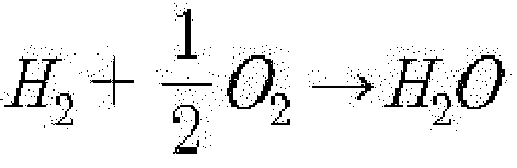
- Here, the amount of water produced at the anode can be calculated as in [Equation 1].

- Qw : Water production amount
- i : Current density
- A : Membrane area
- Mw : Molar mass of water
- F : Faraday constant
- Meanwhile, the
energy storage part 130 may store electrical energy produced by thefuel cell 110. Here, the electrical energy stored in theenergy storage part 130 may be used as power required to operate components constituting the drinkingwater production device 100 according to the embodiment of the present disclosure such as the drinkingwater production part 140, thefirst valve 151, and thecontroller 170. - Water produced by the
fuel cell 110 may be stored in thewater storage tank 120. As illustrated inFIG. 2 , in the drinking water production device of the present disclosure, thewater storage tank 120 may be disposed under thefuel cell 110 and the produced water may flow to thewater storage tank 120 due to gravity. - In the embodiment of the present disclosure, for the water quality management of water stored in the
water storage tank 120, a UV LED to block the growth of microorganisms may be installed to perform a sterilization function. In this case, the UV LED may operate by receiving electric energy produced from thefuel cell 110 as a direct current without conversion of the electric energy. - Meanwhile, the drinking
water production part 140 may produce drinking water by receiving water stored in thewater storage tank 120. In the embodiment of the present disclosure, for example, the drinkingwater production part 140 includes acapacitive deionization part 141 and aremineralization part 142. - The
capacitive deionization part 141 may remove heavy metal ions contained in water supplied from thewater storage tank 120 in an ion adsorption method. Here, thecapacitive deionization part 141 may operate in one mode of an ion adsorption mode in which the ion adsorption method described above is used for producing drinking water, and an ion desorption mode in which adsorbed ions are desorbed. -
FIG. 3A is a view illustrating the general state of thecapacitive deionization part 141,FIG. 3B is a view illustrating a state in which thecapacitive deionization part 141 operates in the ion adsorption mode, andFIG. 3C is a view illustrating a state in which thecapacitive deionization part 141 operates in the ion desorption mode. - While operating in the ion adsorption mode, the
capacitive deionization part 141 may receive power required to operate from theenergy storage part 130. Alternatively, thecapacitive deionization part 141 may operate by receiving electric energy produced by thefuel cell 110 as a direct current without additional conversion of the electric energy. - In addition, electrical energy emitted while the
capacitive deionization part 141 operates in the ion desorption mode may be stored in theenergy storage part 130. - The
remineralization part 142 may produce drinking water by adding minerals to water from which heavy metal ions are removed by thecapacitive deionization part 141. Water passing through thefuel cell 110 and thecapacitive deionization part 141 may have a pH of about 5-6 and may be slightly acidic, and may be very low in the concentration of total dissolved solids (TDS) and thus may not be suitable to be used as drinking water. Accordingly, theremineralization part 142 may produce drinking water by increasing the pH of the water through mineral additives and adding useful ions to the water so as to be suitable to be used as drinking water. - In the embodiment of the present disclosure, the
remineralization part 142 includes stacks of magnesium hydroxide and calcium hydroxide including salt, and when low-pH water passes through theremineralization part 142, hydroxide ions may increase, and thus the pH of the water and the concentrations of magnesium ions and calcium ions may increase such that high-quality drinking water can be produced. - The
first valve 151 may allow drinking water produced by the drinkingwater production part 140 to flow selectively to any one of a drinkingwater supply line 161 and a domesticwater supply line 162. For example, when a supply start signal for supplying drinking water is input to thecontroller 170, thecontroller 170 may control thefirst valve 151 such that water produced by the drinkingwater production part 140 flows to the drinkingwater supply line 161. This will be described in detail later. Here, the supply start signal may be generated when awater supply button 171 installed in the drinkingwater production device 100 as illustrated inFIG. 2 is pressed. - Meanwhile, the drinking
water production device 100 according to the embodiment of the present disclosure may further include asecond valve 152. - The
second valve 152 may control the flow and amount of water supplied to the drinkingwater production part 140 from thewater storage tank 120. Accordingly, thesecond valve 152 may control the flow and amount of water according to the control of thecontroller 170. - Hereinafter, the operation process of the drinking
water production device 100 having the above-described configuration according to the embodiment of the present disclosure will be described with reference toFIGS. 4 and5 . - As in the previous example, when a user presses the
water supply button 171, the supply start signal may be input to thecontroller 170 at S10. In this case, when thecontroller 170 receives the supply start signal, thecontroller 170 may control thesecond valve 152 such that thesecond valve 152 is completely opened at S11. Here, through the opening of thesecond valve 152, water stored in thewater storage tank 120 may flow to thecapacitive deionization part 141 of the drinkingwater production part 140. - In addition, the
controller 170 controls thecapacitive deionization part 141 such that thecapacitive deionization part 141 operates in the ion adsorption mode at S12 so as to remove heavy metal ions from water supplied from thewater storage tank 120. In addition, while the water passing through thecapacitive deionization part 141 passes through theremineralization part 142, hydroxide ions may increase. - Here, in a state in which the
capacitive deionization part 141 is controlled to operate in the ion adsorption mode, thecontroller 170 may control thefirst valve 151 such that the drinking water discharged from theremineralization part 142 flows to the domesticwater supply line 162 for a preset period of initial operation time at S13. That is, water remaining in thecapacitive deionization part 141, theremineralization part 142, and a pipe connecting thecapacitive deionization part 141 with theremineralization part 142 may not be directly supplied as drinking water for the period of initial operation time but may be discharged to the domesticwater supply line 162 for a predetermined period of time such that high-quality drinking water can be supplied. - When the period of initial operation time elapses at S14, the
controller 170 may control thefirst valve 151 at S15 such that the drinking water discharged from theremineralization part 142 flows to the drinkingwater supply line 161, so the drinking water may be supplied to a user. - In the process in which the drinking water is supplied as described above, when a supply cut-off signal is input to the
controller 170 at S16, for example, when thewater supply button 171 is pressed again, thecontroller 170 may control thefirst valve 151 at S17 such that the drinking water discharged from theremineralization part 142 flows to the domesticwater supply line 162 so as to stop the supply of the drinking water. - In addition, the
controller 170 may partially open thesecond valve 152 to allow the flow of only a preset amount of water at S18. Accordingly, while thesecond valve 152 is partially opened, thecontroller 170 may control thecapacitive deionization part 141 such that thecapacitive deionization part 141 operates in the ion desorption mode at S19. Accordingly, heavy metal ions adsorbed to thecapacitive deionization part 141 may be removed therefrom, and electrical energy discharged in this case may be stored in theenergy storage part 130. - In addition, when a preset period of ion desorption time elapses at S20, the
controller 170 may stop the operation of thecapacitive deionization part 141 at S21 so as to stop an ion desorption process. - Referring back to
FIG. 4 , in a state in which the supply start signal is not input, that is, a state in which the drinking water is not supplied, or after the ion desorption process is completed, thecontroller 170 may detect the water level of thewater storage tank 120 at S22, and when the detected water level exceeds a preset reference water level at S23, thecontroller 170 may control thesecond valve 152 to partially open thesecond valve 152 such that only a preset amount of water can flow at S24. In this case, thefirst valve 151 may be controlled at S25 such that water discharged from theremineralization part 142 flows to the domestic water supply line. - Accordingly, in a state in which water required for supplying drinking water later is stored in the
water storage tank 120, some of the water may flow to the domesticwater supply line 162 such that the contamination of water occurring during the stop of the water flow can be minimized. - Meanwhile, in the embodiment of the present disclosure, the domestic
water supply line 162 is connected to amain supply line 200 for supplying domestic water, and themain supply line 200 receives reprocessed water supplied from a water purification facility. - Accordingly, the reprocessed water may be supplied along with water produced in the drinking
water production device 100 according to the embodiment of the present disclosure such that the negative perception of the reprocessed water can be offset. - Although the embodiment of the present disclosure has been shown and described, it will be appreciated that those skilled in the art to which the present disclosure pertains may vary the present embodiment without departing from the principle or spirit of the present disclosure. The scope of the present disclosure will be defined by the appended claims and equivalents thereof.
Claims (8)
- A hydrogen-based decentralized drinking water production device (100) characterized in that the device (100) comprises:a fuel cell (110) which produces electrical energy and water by receiving hydrogen and oxygen;an energy storage part (130) in which the electrical energy produced by the fuel cell (110) is stored;a water storage tank (120) in which the water produced by the fuel cell (110) is stored;a drinking water production part (140) which produces drinking water by receiving the water stored in the water storage tank (120); anda first valve (151) allowing the drinking water produced by the drinking water production part (140) to flow selectively to one of a drinking water supply line (161) and a domestic water supply line (162).
- The device (100) of claim 1, characterized in that the device (100) further comprises:
a second valve (152) which regulates a flow of the water supplied to the drinking water production part (140) from the water storage tank (120). - The device (100) of claim 2, characterized in that the drinking water production part (140) comprises:a capacitive deionization part (141) which removes heavy metal ions from the water supplied from the water storage tank (120) in an ion adsorption method, anda remineralization part (142) which produces drinking water by adding minerals to water from which the heavy metal ions are removed by the capacitive deionization part (141).
- The device (100) of claim 3, characterized in that the capacitive deionization part (141) operates in one mode of an ion adsorption mode in which heavy metal ions are removed through the ion adsorption method and an ion desorption mode in which adsorbed ions are desorbed; operates by using DC power supplied from the energy storage part (130) or the fuel cell (110) in the ion adsorption mode; and stores electrical energy released in the ion desorption mode in the energy storage part (130).
- The device (100) of claim 4, characterized in that the device (100) further comprises:a controller (170) which controls operations of the first valve (151), the second valve (152), and the capacitive deionization part (141),wherein when a supply start signal for supplying drinking water is input to the controller (170), the controller (170) controls the second valve (152) such that the second valve (152) is opened, controls the first valve (151) such that drinking water discharged from the remineralization part (142) flows to the domestic water supply line (162) for a preset period of initial operation time in a state in which the capacitive deionization part (141) is controlled to operate in the ion adsorption mode, and then controls the first valve (151) such that the drinking water flows to the drinking water supply line (161).
- The device (100) of claim 5, characterized in that when a supply cut-off signal is input to the controller (170) to stop the supply of the drinking water, the controller (170) controls the first valve (151) such that the drinking water discharged from the remineralization part (142) flows to the domestic water supply line (162) for a preset period of ion desorption time, controls the second valve (152) such that only a preset amount of water flows, and controls the capacitive deionization part (141) such that the capacitive deionization part (141) operates in the ion desorption mode.
- The device (100) of claim 6, characterized in that when the period of ion desorption time elapses, the controller (170) controls the second valve (152) such that the second valve (152) is shut off.
- The device (100) of claim 7, characterized in that when a water level of the water storage tank (120) exceeds a preset reference water level in a state in which the supply start signal is not input and the second valve (152) is shut off, the controller (170) controls the second valve (152) such that only a preset amount of water flows.
Applications Claiming Priority (1)
| Application Number | Priority Date | Filing Date | Title |
|---|---|---|---|
| KR1020210050931A KR102536593B1 (en) | 2021-04-20 | 2021-04-20 | Decentralized portable water production apparatus using hydrogen gas |
Publications (2)
| Publication Number | Publication Date |
|---|---|
| EP4074663A1 true EP4074663A1 (en) | 2022-10-19 |
| EP4074663B1 EP4074663B1 (en) | 2025-07-30 |
Family
ID=81328317
Family Applications (1)
| Application Number | Title | Priority Date | Filing Date |
|---|---|---|---|
| EP22163130.2A Active EP4074663B1 (en) | 2021-04-20 | 2022-03-21 | Hydrogen-based fuel cell decentralized drinking water production device |
Country Status (2)
| Country | Link |
|---|---|
| EP (1) | EP4074663B1 (en) |
| KR (1) | KR102536593B1 (en) |
Citations (4)
| Publication number | Priority date | Publication date | Assignee | Title |
|---|---|---|---|---|
| US5980716A (en) * | 1995-12-06 | 1999-11-09 | Tokyo Gas Co., Ltd. | Water treatment apparatus for a fuel cell system |
| US20040038089A1 (en) * | 2002-04-16 | 2004-02-26 | Claus Hoffjann | Method for treating and distributing water generated in a self-contained water using unit |
| US20100055508A1 (en) * | 2008-08-27 | 2010-03-04 | Idatech, Llc | Fuel cell systems with water recovery from fuel cell effluent |
| US20170033381A1 (en) * | 2015-07-29 | 2017-02-02 | Thomas Michael Reilly | Resource Tower |
Family Cites Families (3)
| Publication number | Priority date | Publication date | Assignee | Title |
|---|---|---|---|---|
| KR20030030583A (en) * | 2001-10-11 | 2003-04-18 | (주)크로바 환경 | Water Purification System and Water Purification Method for Household Water |
| KR101992312B1 (en) * | 2016-08-05 | 2019-06-25 | 두산중공업 주식회사 | Water treating apparatus for saving energy and water treating method using the same |
| KR102427273B1 (en) * | 2019-05-01 | 2022-07-29 | 지세영 | Multipurpose reuse apparatus for Hydrogen vehicles car exhaust water |
-
2021
- 2021-04-20 KR KR1020210050931A patent/KR102536593B1/en active Active
-
2022
- 2022-03-21 EP EP22163130.2A patent/EP4074663B1/en active Active
Patent Citations (4)
| Publication number | Priority date | Publication date | Assignee | Title |
|---|---|---|---|---|
| US5980716A (en) * | 1995-12-06 | 1999-11-09 | Tokyo Gas Co., Ltd. | Water treatment apparatus for a fuel cell system |
| US20040038089A1 (en) * | 2002-04-16 | 2004-02-26 | Claus Hoffjann | Method for treating and distributing water generated in a self-contained water using unit |
| US20100055508A1 (en) * | 2008-08-27 | 2010-03-04 | Idatech, Llc | Fuel cell systems with water recovery from fuel cell effluent |
| US20170033381A1 (en) * | 2015-07-29 | 2017-02-02 | Thomas Michael Reilly | Resource Tower |
Also Published As
| Publication number | Publication date |
|---|---|
| KR102536593B1 (en) | 2023-05-30 |
| EP4074663B1 (en) | 2025-07-30 |
| KR20220145956A (en) | 2022-11-01 |
Similar Documents
| Publication | Publication Date | Title |
|---|---|---|
| US11710840B2 (en) | Carbon dioxide utilization system, and complex power generation system using the same | |
| KR101955696B1 (en) | Secondary battery using carbon dioxide and complex electric power generation system having the same | |
| AU2009304585A1 (en) | Treatment of solutions or wastewater | |
| US20160064756A1 (en) | Fuel cell system and method of controlling the fuel cell system | |
| KR102205629B1 (en) | Secondary battery using carbon dioxide and complex electric power generation system having the same | |
| EP4517888A1 (en) | Carbon dioxide capture and carbon resource utilization system for fuel cell and method using same | |
| JP2001232394A (en) | Fuel cell water treatment equipment | |
| EP4074663B1 (en) | Hydrogen-based fuel cell decentralized drinking water production device | |
| US8900762B2 (en) | Fuel cell with recovering unit and method for driving the same | |
| KR101986642B1 (en) | Fuel cell systme having hydrogen generation apparatus using carbon dioxide | |
| JP5353034B2 (en) | Fuel cell power generator | |
| US20250289716A1 (en) | Carbon dioxide capture and carbon resource utilization system, for fuel cell, using boil-off gas generated from liquefied natural gas | |
| KR102001213B1 (en) | Fuel cell system having hydrogen generating and carbon dioxide removing apparatus using carbon dioxide | |
| CN111206264A (en) | Electric energy supply type electrochemical reactor and use method thereof | |
| Zhang et al. | Study on the influence characteristics of multi-working condition parameters on membrane electrode type CO2 electrolyzer | |
| KR20070081285A (en) | Gas-liquid separator for fuel cell | |
| KR101955697B1 (en) | Secondary battery using carbon dioxide and complex electric power generation system having the same | |
| JP2009245702A (en) | Water processing unit for fuel cell power generation system | |
| KR102163935B1 (en) | Secondary battery using carbon dioxide and complex electric power generation system having the same | |
| CN117396637A (en) | Hydrogen production system using ammonia and fuel cell using ammonia | |
| JP5286851B2 (en) | Fuel cell power generator | |
| JP2006114413A (en) | Water quality management method for fuel cell power generator | |
| KR101955698B1 (en) | Complex electric power generation system using carbon dioxide | |
| JP5380868B2 (en) | Condensed water decay prevention method and fuel cell power generator | |
| Zecevic et al. | Direct carbon fuel cell with hydroxide electrolyte: cell performance during initial stage of a long term operation |
Legal Events
| Date | Code | Title | Description |
|---|---|---|---|
| PUAI | Public reference made under article 153(3) epc to a published international application that has entered the european phase |
Free format text: ORIGINAL CODE: 0009012 |
|
| STAA | Information on the status of an ep patent application or granted ep patent |
Free format text: STATUS: REQUEST FOR EXAMINATION WAS MADE |
|
| 17P | Request for examination filed |
Effective date: 20220321 |
|
| AK | Designated contracting states |
Kind code of ref document: A1 Designated state(s): AL AT BE BG CH CY CZ DE DK EE ES FI FR GB GR HR HU IE IS IT LI LT LU LV MC MK MT NL NO PL PT RO RS SE SI SK SM TR |
|
| RBV | Designated contracting states (corrected) |
Designated state(s): AL AT BE BG CH CY CZ DE DK EE ES FI FR GB GR HR HU IE IS IT LI LT LU LV MC MK MT NL NO PL PT RO RS SE SI SK SM TR |
|
| GRAP | Despatch of communication of intention to grant a patent |
Free format text: ORIGINAL CODE: EPIDOSNIGR1 |
|
| STAA | Information on the status of an ep patent application or granted ep patent |
Free format text: STATUS: GRANT OF PATENT IS INTENDED |
|
| RIC1 | Information provided on ipc code assigned before grant |
Ipc: C02F 103/02 20060101ALN20250203BHEP Ipc: C02F 1/68 20060101ALN20250203BHEP Ipc: H01M 8/1004 20160101ALN20250203BHEP Ipc: H01M 8/06 20160101ALN20250203BHEP Ipc: C02F 101/20 20060101ALN20250203BHEP Ipc: C02F 1/469 20060101AFI20250203BHEP |
|
| INTG | Intention to grant announced |
Effective date: 20250221 |
|
| GRAS | Grant fee paid |
Free format text: ORIGINAL CODE: EPIDOSNIGR3 |
|
| GRAA | (expected) grant |
Free format text: ORIGINAL CODE: 0009210 |
|
| STAA | Information on the status of an ep patent application or granted ep patent |
Free format text: STATUS: THE PATENT HAS BEEN GRANTED |
|
| AK | Designated contracting states |
Kind code of ref document: B1 Designated state(s): AL AT BE BG CH CY CZ DE DK EE ES FI FR GB GR HR HU IE IS IT LI LT LU LV MC MK MT NL NO PL PT RO RS SE SI SK SM TR |
|
| REG | Reference to a national code |
Ref country code: GB Ref legal event code: FG4D |
|
| REG | Reference to a national code |
Ref country code: CH Ref legal event code: EP |
|
| REG | Reference to a national code |
Ref country code: DE Ref legal event code: R096 Ref document number: 602022018278 Country of ref document: DE |
|
| REG | Reference to a national code |
Ref country code: IE Ref legal event code: FG4D |
|
| REG | Reference to a national code |
Ref country code: NL Ref legal event code: MP Effective date: 20250730 |
|
| REG | Reference to a national code |
Ref country code: AT Ref legal event code: MK05 Ref document number: 1818800 Country of ref document: AT Kind code of ref document: T Effective date: 20250730 |
|
| PG25 | Lapsed in a contracting state [announced via postgrant information from national office to epo] |
Ref country code: PT Free format text: LAPSE BECAUSE OF FAILURE TO SUBMIT A TRANSLATION OF THE DESCRIPTION OR TO PAY THE FEE WITHIN THE PRESCRIBED TIME-LIMIT Effective date: 20251202 |
|
| PG25 | Lapsed in a contracting state [announced via postgrant information from national office to epo] |
Ref country code: IS Free format text: LAPSE BECAUSE OF FAILURE TO SUBMIT A TRANSLATION OF THE DESCRIPTION OR TO PAY THE FEE WITHIN THE PRESCRIBED TIME-LIMIT Effective date: 20251130 |
|
| PG25 | Lapsed in a contracting state [announced via postgrant information from national office to epo] |
Ref country code: NO Free format text: LAPSE BECAUSE OF FAILURE TO SUBMIT A TRANSLATION OF THE DESCRIPTION OR TO PAY THE FEE WITHIN THE PRESCRIBED TIME-LIMIT Effective date: 20251030 |
|
| REG | Reference to a national code |
Ref country code: LT Ref legal event code: MG9D |
|
| PG25 | Lapsed in a contracting state [announced via postgrant information from national office to epo] |
Ref country code: AT Free format text: LAPSE BECAUSE OF FAILURE TO SUBMIT A TRANSLATION OF THE DESCRIPTION OR TO PAY THE FEE WITHIN THE PRESCRIBED TIME-LIMIT Effective date: 20250730 |
|
| PG25 | Lapsed in a contracting state [announced via postgrant information from national office to epo] |
Ref country code: FI Free format text: LAPSE BECAUSE OF FAILURE TO SUBMIT A TRANSLATION OF THE DESCRIPTION OR TO PAY THE FEE WITHIN THE PRESCRIBED TIME-LIMIT Effective date: 20250730 |
|
| PG25 | Lapsed in a contracting state [announced via postgrant information from national office to epo] |
Ref country code: HR Free format text: LAPSE BECAUSE OF FAILURE TO SUBMIT A TRANSLATION OF THE DESCRIPTION OR TO PAY THE FEE WITHIN THE PRESCRIBED TIME-LIMIT Effective date: 20250730 Ref country code: NL Free format text: LAPSE BECAUSE OF FAILURE TO SUBMIT A TRANSLATION OF THE DESCRIPTION OR TO PAY THE FEE WITHIN THE PRESCRIBED TIME-LIMIT Effective date: 20250730 |
|
| PG25 | Lapsed in a contracting state [announced via postgrant information from national office to epo] |
Ref country code: GR Free format text: LAPSE BECAUSE OF FAILURE TO SUBMIT A TRANSLATION OF THE DESCRIPTION OR TO PAY THE FEE WITHIN THE PRESCRIBED TIME-LIMIT Effective date: 20251031 |
|
| PG25 | Lapsed in a contracting state [announced via postgrant information from national office to epo] |
Ref country code: SE Free format text: LAPSE BECAUSE OF FAILURE TO SUBMIT A TRANSLATION OF THE DESCRIPTION OR TO PAY THE FEE WITHIN THE PRESCRIBED TIME-LIMIT Effective date: 20250730 |
|
| PG25 | Lapsed in a contracting state [announced via postgrant information from national office to epo] |
Ref country code: LV Free format text: LAPSE BECAUSE OF FAILURE TO SUBMIT A TRANSLATION OF THE DESCRIPTION OR TO PAY THE FEE WITHIN THE PRESCRIBED TIME-LIMIT Effective date: 20250730 |
|
| PG25 | Lapsed in a contracting state [announced via postgrant information from national office to epo] |
Ref country code: PL Free format text: LAPSE BECAUSE OF FAILURE TO SUBMIT A TRANSLATION OF THE DESCRIPTION OR TO PAY THE FEE WITHIN THE PRESCRIBED TIME-LIMIT Effective date: 20250730 Ref country code: BG Free format text: LAPSE BECAUSE OF FAILURE TO SUBMIT A TRANSLATION OF THE DESCRIPTION OR TO PAY THE FEE WITHIN THE PRESCRIBED TIME-LIMIT Effective date: 20250730 |
|
| PG25 | Lapsed in a contracting state [announced via postgrant information from national office to epo] |
Ref country code: RS Free format text: LAPSE BECAUSE OF FAILURE TO SUBMIT A TRANSLATION OF THE DESCRIPTION OR TO PAY THE FEE WITHIN THE PRESCRIBED TIME-LIMIT Effective date: 20251030 |
|
| PG25 | Lapsed in a contracting state [announced via postgrant information from national office to epo] |
Ref country code: ES Free format text: LAPSE BECAUSE OF FAILURE TO SUBMIT A TRANSLATION OF THE DESCRIPTION OR TO PAY THE FEE WITHIN THE PRESCRIBED TIME-LIMIT Effective date: 20250730 |
|
| PG25 | Lapsed in a contracting state [announced via postgrant information from national office to epo] |
Ref country code: SM Free format text: LAPSE BECAUSE OF FAILURE TO SUBMIT A TRANSLATION OF THE DESCRIPTION OR TO PAY THE FEE WITHIN THE PRESCRIBED TIME-LIMIT Effective date: 20250730 |
|
| PG25 | Lapsed in a contracting state [announced via postgrant information from national office to epo] |
Ref country code: DK Free format text: LAPSE BECAUSE OF FAILURE TO SUBMIT A TRANSLATION OF THE DESCRIPTION OR TO PAY THE FEE WITHIN THE PRESCRIBED TIME-LIMIT Effective date: 20250730 |
|
| PGFP | Annual fee paid to national office [announced via postgrant information from national office to epo] |
Ref country code: DE Payment date: 20260324 Year of fee payment: 5 |
|
| PG25 | Lapsed in a contracting state [announced via postgrant information from national office to epo] |
Ref country code: IT Free format text: LAPSE BECAUSE OF FAILURE TO SUBMIT A TRANSLATION OF THE DESCRIPTION OR TO PAY THE FEE WITHIN THE PRESCRIBED TIME-LIMIT Effective date: 20250730 |
|
| PG25 | Lapsed in a contracting state [announced via postgrant information from national office to epo] |
Ref country code: CZ Free format text: LAPSE BECAUSE OF FAILURE TO SUBMIT A TRANSLATION OF THE DESCRIPTION OR TO PAY THE FEE WITHIN THE PRESCRIBED TIME-LIMIT Effective date: 20250730 |
|
| PG25 | Lapsed in a contracting state [announced via postgrant information from national office to epo] |
Ref country code: SK Free format text: LAPSE BECAUSE OF FAILURE TO SUBMIT A TRANSLATION OF THE DESCRIPTION OR TO PAY THE FEE WITHIN THE PRESCRIBED TIME-LIMIT Effective date: 20250730 Ref country code: EE Free format text: LAPSE BECAUSE OF FAILURE TO SUBMIT A TRANSLATION OF THE DESCRIPTION OR TO PAY THE FEE WITHIN THE PRESCRIBED TIME-LIMIT Effective date: 20250730 |
|
| REG | Reference to a national code |
Ref country code: DE Ref legal event code: R097 Ref document number: 602022018278 Country of ref document: DE |
|
| PLBE | No opposition filed within time limit |
Free format text: ORIGINAL CODE: 0009261 |
|
| STAA | Information on the status of an ep patent application or granted ep patent |
Free format text: STATUS: NO OPPOSITION FILED WITHIN TIME LIMIT |
|
| REG | Reference to a national code |
Ref country code: CH Ref legal event code: L10 Free format text: ST27 STATUS EVENT CODE: U-0-0-L10-L00 (AS PROVIDED BY THE NATIONAL OFFICE) Effective date: 20260611 |
|
| PG25 | Lapsed in a contracting state [announced via postgrant information from national office to epo] |
Ref country code: LT Free format text: LAPSE BECAUSE OF FAILURE TO SUBMIT A TRANSLATION OF THE DESCRIPTION OR TO PAY THE FEE WITHIN THE PRESCRIBED TIME-LIMIT Effective date: 20250730 |
|
| 26N | No opposition filed |
Effective date: 20260501 |