EP4074627B1 - Storage device and system and control method - Google Patents
Storage device and system and control method Download PDFInfo
- Publication number
- EP4074627B1 EP4074627B1 EP21776624.5A EP21776624A EP4074627B1 EP 4074627 B1 EP4074627 B1 EP 4074627B1 EP 21776624 A EP21776624 A EP 21776624A EP 4074627 B1 EP4074627 B1 EP 4074627B1
- Authority
- EP
- European Patent Office
- Prior art keywords
- robot
- temporary storage
- storage position
- target
- channel
- Prior art date
- Legal status (The legal status is an assumption and is not a legal conclusion. Google has not performed a legal analysis and makes no representation as to the accuracy of the status listed.)
- Active
Links
Images






Classifications
-
- B—PERFORMING OPERATIONS; TRANSPORTING
- B65—CONVEYING; PACKING; STORING; HANDLING THIN OR FILAMENTARY MATERIAL
- B65G—TRANSPORT OR STORAGE DEVICES, e.g. CONVEYORS FOR LOADING OR TIPPING, SHOP CONVEYOR SYSTEMS OR PNEUMATIC TUBE CONVEYORS
- B65G1/00—Storing articles, individually or in orderly arrangement, in warehouses or magazines
- B65G1/02—Storage devices
- B65G1/04—Storage devices mechanical
-
- B—PERFORMING OPERATIONS; TRANSPORTING
- B25—HAND TOOLS; PORTABLE POWER-DRIVEN TOOLS; MANIPULATORS
- B25J—MANIPULATORS; CHAMBERS PROVIDED WITH MANIPULATION DEVICES
- B25J11/00—Manipulators not otherwise provided for
- B25J11/008—Manipulators for service tasks
-
- B—PERFORMING OPERATIONS; TRANSPORTING
- B25—HAND TOOLS; PORTABLE POWER-DRIVEN TOOLS; MANIPULATORS
- B25J—MANIPULATORS; CHAMBERS PROVIDED WITH MANIPULATION DEVICES
- B25J13/00—Controls for manipulators
- B25J13/08—Controls for manipulators by means of sensing devices, e.g. viewing or touching devices
- B25J13/088—Controls for manipulators by means of sensing devices, e.g. viewing or touching devices with position, velocity or acceleration sensors
- B25J13/089—Determining the position of the robot with reference to its environment
-
- B—PERFORMING OPERATIONS; TRANSPORTING
- B25—HAND TOOLS; PORTABLE POWER-DRIVEN TOOLS; MANIPULATORS
- B25J—MANIPULATORS; CHAMBERS PROVIDED WITH MANIPULATION DEVICES
- B25J9/00—Program-controlled manipulators
- B25J9/16—Program controls
- B25J9/1656—Program controls characterised by programming, planning systems for manipulators
- B25J9/1661—Program controls characterised by programming, planning systems for manipulators characterised by task planning, object-oriented languages
-
- B—PERFORMING OPERATIONS; TRANSPORTING
- B25—HAND TOOLS; PORTABLE POWER-DRIVEN TOOLS; MANIPULATORS
- B25J—MANIPULATORS; CHAMBERS PROVIDED WITH MANIPULATION DEVICES
- B25J9/00—Program-controlled manipulators
- B25J9/16—Program controls
- B25J9/1656—Program controls characterised by programming, planning systems for manipulators
- B25J9/1664—Program controls characterised by programming, planning systems for manipulators characterised by motion, path, trajectory planning
-
- B—PERFORMING OPERATIONS; TRANSPORTING
- B25—HAND TOOLS; PORTABLE POWER-DRIVEN TOOLS; MANIPULATORS
- B25J—MANIPULATORS; CHAMBERS PROVIDED WITH MANIPULATION DEVICES
- B25J9/00—Program-controlled manipulators
- B25J9/16—Program controls
- B25J9/1679—Program controls characterised by the tasks executed
- B25J9/1682—Dual arm manipulator; Coordination of several manipulators
-
- B—PERFORMING OPERATIONS; TRANSPORTING
- B25—HAND TOOLS; PORTABLE POWER-DRIVEN TOOLS; MANIPULATORS
- B25J—MANIPULATORS; CHAMBERS PROVIDED WITH MANIPULATION DEVICES
- B25J9/00—Program-controlled manipulators
- B25J9/16—Program controls
- B25J9/1679—Program controls characterised by the tasks executed
- B25J9/1684—Tracking a line or surface by means of sensors
-
- B—PERFORMING OPERATIONS; TRANSPORTING
- B65—CONVEYING; PACKING; STORING; HANDLING THIN OR FILAMENTARY MATERIAL
- B65G—TRANSPORT OR STORAGE DEVICES, e.g. CONVEYORS FOR LOADING OR TIPPING, SHOP CONVEYOR SYSTEMS OR PNEUMATIC TUBE CONVEYORS
- B65G1/00—Storing articles, individually or in orderly arrangement, in warehouses or magazines
- B65G1/02—Storage devices
- B65G1/04—Storage devices mechanical
- B65G1/0407—Storage devices mechanical using stacker cranes
-
- B—PERFORMING OPERATIONS; TRANSPORTING
- B65—CONVEYING; PACKING; STORING; HANDLING THIN OR FILAMENTARY MATERIAL
- B65G—TRANSPORT OR STORAGE DEVICES, e.g. CONVEYORS FOR LOADING OR TIPPING, SHOP CONVEYOR SYSTEMS OR PNEUMATIC TUBE CONVEYORS
- B65G1/00—Storing articles, individually or in orderly arrangement, in warehouses or magazines
- B65G1/02—Storage devices
- B65G1/04—Storage devices mechanical
- B65G1/0407—Storage devices mechanical using stacker cranes
- B65G1/0421—Storage devices mechanical using stacker cranes with control for stacker crane operations
-
- B—PERFORMING OPERATIONS; TRANSPORTING
- B65—CONVEYING; PACKING; STORING; HANDLING THIN OR FILAMENTARY MATERIAL
- B65G—TRANSPORT OR STORAGE DEVICES, e.g. CONVEYORS FOR LOADING OR TIPPING, SHOP CONVEYOR SYSTEMS OR PNEUMATIC TUBE CONVEYORS
- B65G1/00—Storing articles, individually or in orderly arrangement, in warehouses or magazines
- B65G1/02—Storage devices
- B65G1/04—Storage devices mechanical
- B65G1/0471—Storage devices mechanical with access from beneath
-
- B—PERFORMING OPERATIONS; TRANSPORTING
- B65—CONVEYING; PACKING; STORING; HANDLING THIN OR FILAMENTARY MATERIAL
- B65G—TRANSPORT OR STORAGE DEVICES, e.g. CONVEYORS FOR LOADING OR TIPPING, SHOP CONVEYOR SYSTEMS OR PNEUMATIC TUBE CONVEYORS
- B65G1/00—Storing articles, individually or in orderly arrangement, in warehouses or magazines
- B65G1/02—Storage devices
- B65G1/04—Storage devices mechanical
- B65G1/0492—Storage devices mechanical with cars adapted to travel in storage aisles
-
- B—PERFORMING OPERATIONS; TRANSPORTING
- B65—CONVEYING; PACKING; STORING; HANDLING THIN OR FILAMENTARY MATERIAL
- B65G—TRANSPORT OR STORAGE DEVICES, e.g. CONVEYORS FOR LOADING OR TIPPING, SHOP CONVEYOR SYSTEMS OR PNEUMATIC TUBE CONVEYORS
- B65G1/00—Storing articles, individually or in orderly arrangement, in warehouses or magazines
- B65G1/02—Storage devices
- B65G1/04—Storage devices mechanical
- B65G1/137—Storage devices mechanical with arrangements or automatic control means for selecting which articles are to be removed
-
- B—PERFORMING OPERATIONS; TRANSPORTING
- B65—CONVEYING; PACKING; STORING; HANDLING THIN OR FILAMENTARY MATERIAL
- B65G—TRANSPORT OR STORAGE DEVICES, e.g. CONVEYORS FOR LOADING OR TIPPING, SHOP CONVEYOR SYSTEMS OR PNEUMATIC TUBE CONVEYORS
- B65G1/00—Storing articles, individually or in orderly arrangement, in warehouses or magazines
- B65G1/02—Storage devices
- B65G1/04—Storage devices mechanical
- B65G1/137—Storage devices mechanical with arrangements or automatic control means for selecting which articles are to be removed
- B65G1/1373—Storage devices mechanical with arrangements or automatic control means for selecting which articles are to be removed for fulfilling orders in warehouses
- B65G1/1375—Storage devices mechanical with arrangements or automatic control means for selecting which articles are to be removed for fulfilling orders in warehouses the orders being assembled on a commissioning stacker-crane or truck
-
- B—PERFORMING OPERATIONS; TRANSPORTING
- B65—CONVEYING; PACKING; STORING; HANDLING THIN OR FILAMENTARY MATERIAL
- B65G—TRANSPORT OR STORAGE DEVICES, e.g. CONVEYORS FOR LOADING OR TIPPING, SHOP CONVEYOR SYSTEMS OR PNEUMATIC TUBE CONVEYORS
- B65G1/00—Storing articles, individually or in orderly arrangement, in warehouses or magazines
- B65G1/02—Storage devices
- B65G1/04—Storage devices mechanical
- B65G1/137—Storage devices mechanical with arrangements or automatic control means for selecting which articles are to be removed
- B65G1/1373—Storage devices mechanical with arrangements or automatic control means for selecting which articles are to be removed for fulfilling orders in warehouses
- B65G1/1378—Storage devices mechanical with arrangements or automatic control means for selecting which articles are to be removed for fulfilling orders in warehouses the orders being assembled on fixed commissioning areas remote from the storage areas
-
- G—PHYSICS
- G05—CONTROLLING; REGULATING
- G05B—CONTROL OR REGULATING SYSTEMS IN GENERAL; FUNCTIONAL ELEMENTS OF SUCH SYSTEMS; MONITORING OR TESTING ARRANGEMENTS FOR SUCH SYSTEMS OR ELEMENTS
- G05B19/00—Program-control systems
- G05B19/02—Program-control systems electric
- G05B19/418—Total factory control, i.e. centrally controlling a plurality of machines, e.g. direct or distributed numerical control [DNC], flexible manufacturing systems [FMS], integrated manufacturing systems [IMS] or computer integrated manufacturing [CIM]
- G05B19/4189—Total factory control, i.e. centrally controlling a plurality of machines, e.g. direct or distributed numerical control [DNC], flexible manufacturing systems [FMS], integrated manufacturing systems [IMS] or computer integrated manufacturing [CIM] characterised by the transport system
- G05B19/41895—Total factory control, i.e. centrally controlling a plurality of machines, e.g. direct or distributed numerical control [DNC], flexible manufacturing systems [FMS], integrated manufacturing systems [IMS] or computer integrated manufacturing [CIM] characterised by the transport system using automatic guided vehicles [AGV]
Definitions
- the present disclosure relates to the field of warehousing technologies, and in particular, to a warehousing apparatus, system, and a control method.
- the existing warehousing industry mostly uses robots integrated with automatic climbing and moving capabilities to access and transfer cargoes. However, because there are too many storage actions for the robots in accessing the cargoes, this leads to low efficiency for in-warehouse and ex-warehouse of the cargoes.
- CN109987366A relates to an unmanned warehousing system and an in-warehouse and ex-warehouse method.
- the system comprises two-layered channel supporting frames, in which a lower layer is used as a passage for an automatic vehicle, and an upper layer is used as a passage for a normalized container.
- Said document discloses a warehousing apparatus according to the preamble of claim 1.
- the invention provides a warehousing apparatus according to claim 1, an in-warehouse control method according to claim 12, an ex-warehouse control method according to claim 17 and a warehousing system according to claim 20 to solve or alleviate one or more technical problems in the related art.
- the first robot directly accesses the cargoes on the temporary storage layer board, which avoids the operation of extending the robot arm to a shelf layer board, and improve the efficiency of accessing cargoes;
- the temporary storage layer board may temporarily store the cargoes, and the storage positions provided by the storage layer board may store the cargoes for a long time, which is convenient to cooperate the temporary storage layer board with the storage layer board to improve the ex-warehouse and in-warehouse efficiency of the cargoes;
- the first robot channel and the second robot channel are respectively formed, which can avoid the first robot and the second robot sharing a same driving channel, improve the driving efficiency of the first robot and the second robot, and then improve the ex-warehouse and in-warehouse efficiency.
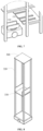
- FIG. 1 shows a three-dimensional schematic structural diagram of a warehousing apparatus according to an embodiment of the present disclosure.
- the warehousing apparatus 1000 includes at least one temporary storage layer board 120, where the temporary storage layer board 120 is used to provide at least one temporary storage position; a plurality of shelves 100, where each of the shelves 100 include at least one storage layer board 130 and a plurality of columns 110 arranged at an interval in a horizontal direction, and the storage layer board 130 is used to provide at least one storage position.
- the temporary storage layer board 120 is provided with furcal grooves 121, and each of the furcal grooves 121 is used to cooperate with a furcal arm 210 of the first robot 200; and the storage layer board 130 is arranged at an interval with the temporary storage layer board 120 in a vertical direction through the columns 110.
- the plurality of shelves 100 may be single-row shelves, double-row shelves or multi-row shelves; the number of the plurality of shelves 100 include two or more; and the plurality of shelves 100 may be arranged in columns (refer to FIG. 1 and FIG. 2 ), in rows (refer to FIG. 3 ), or in a matrix.
- the number of rows of, the number of, and the arrangement manner of the plurality of shelves 100 may be selected and adjusted according to actual needs, and both the number of and the arrangement manner of the plurality of shelves 100 are not limited in the embodiment of the present disclosure.
- the first robot 200 may be an AGV (Automated Guided Vehicle, AGV for short) vehicle with the furcal arm 210, and the furcal arm 210 thereof may be arranged on the top of the first robot 200, and may also be arranged on the side of the first robot 200.
- AGV Automated Guided Vehicle
- the arrangement manner of the furcal arm 210 of the first robot 200 is not limited in the embodiment of the present disclosure.
- the temporary storage layer board 120 in a case that the temporary storage layer board 120 is located at the bottom layer of the columns 110, the temporary storage layer board 120, the columns 110 located on the side of the furcal groove of the temporary storage layer board 120, and the ground may form a first driving channel 141 for the first robot 200 to drive.
- the first driving channel 141 for the first robot 200 to drive is formed between the temporary storage layer board 120 and the columns 110 located on the side of the furcal groove of the temporary storage layer board 120, so that the first robot 200 may drive in any layer of the shelf 100, which is convenient for the first robot 200 to cooperate with the temporary storage layer board 120 and avoids occupying a channel outside the shelf 100.
- the shelf 100 may further include: cross beams 150, where each of the cross beams 150 is arranged in a horizontal direction and is used for fixing short sides of the temporary storage layer board 120 and the storage layer board 130 on the columns 110.
- FIG. 5 shows a schematic structural diagram of a shelf 100 according to another embodiment of the present disclosure.
- the structure of the shelf 100 is similar to the structure of the shelf 100 in FIG. 1 , the difference is that, as shown in FIG. 5 , a second driving channel 142 for the first robot 200 to drive is formed between the temporary storage layer board 120 and the columns 110 located at the first end of the temporary storage layer board 120.
- the first robot 200 may pass through the shelf 100 in the second driving channel 142, so that a driving distance of the first robot 200 may be shortened, and transfer efficiency of cargo boxes may be improved.
- the shelf 100 may further include: a support column 160 arranged at the first end of the temporary storage layer board 120 for support.
- the temporary storage layer board 120 includes a plurality of temporary storage boards, each of the temporary storage boards is provided with a furcal groove 121, and a third driving channel for the first robot 200 to drive is formed between at least two temporary storage boards (refer to 143 in FIG. 9 ).
- the first robot 200 may pass through the shelf 100 between any two temporary storage boards of the temporary storage layer board 120, so that a driving distance of the first robot 200 may be shortened, and transfer efficiency of cargo boxes may be improved.
- the second robot channel 310 is formed between adjacent shelves 100, so that the second robot 300 may drive in the second robot channel 310, so as to transfer cargoes between the temporary storage layer board 120 and the storage layer board 130.
- the cargoes temporarily stored in the temporary storage layer board 120 are transferred to the storage layer board 130 for in-warehouse storage, or the cargoes stored in the storage layer board 130 are transferred to the temporary storage layer board 120 for the ex-warehouse temporary storage, which may improve the access efficiency and the ex-warehouse and in-warehouse efficiency of the cargoes;
- the second robot channel 310 does not coincide with the driving channel of the first robot 200, which may avoid the first robot 200 and the second robot 300 sharing a same driving channel, improve the cooperation efficiency of the first robot 200 and the second robot 300, and then improve the ex-warehouse and in-warehouse efficiency.
- the second robot 300 integrated with a lifting mechanism 320 and an access mechanism 330 is generally used to transfer and access cargoes.
- the cost of the second robot 300 is relatively high, and there are relatively long distances between a docking port 400 for the cargoes and each temporary storage position and each storage position in the shelf 100, the ex-warehouse and in-warehouse costs of the cargoes per unit time are relatively high, and the efficiency is relatively low.
- the warehousing apparatus 1000 of the embodiment of the present disclosure may be configured with the second robot 300 to transfer cargoes between the temporary storage layer board 120 and the storage layer board 130, and may be configured with the first robot 200 to transfer and access the cargoes on the temporary storage layer board 120, where the first robot 200 may not have a lifting mechanism, and the cost thereof is much lower than that of the second robot 300.
- one second robot 300 may be equipped with a plurality of first robots 200 for coordinating access of cargoes, which may reduce the ex-warehouse and in-warehouse costs of the cargoes per unit time and may improve the ex-warehouse and in-warehouse efficiency of the cargoes.
- the first robot 200 may be a robot that accesses and transfers one box of cargoes once
- the second robot 300 may be a robot that accesses and transfers a plurality of boxes of cargoes once.
- the second robot 300 is configured to transfer cargoes between the temporary storage layer board 120 and the storage layer board 130
- the first robot 200 is configured to transfer and access cargoes on the temporary storage layer board 120, which may reduce the ex-warehouse and in-warehouse costs of the cargoes per unit time and may improve the ex-warehouse and in-warehouse efficiency of the cargoes.
- the temporary storage layer board includes a plurality of temporary storage boards, and each of the temporary storage boards is provided with a furcal groove.
- the first robot channel includes a third driving channel 143, and the third driving channel 143 is located between at least two temporary storage boards.
- a width of the third driving channel 143 may be one, two, three, or more times the width of the temporary storage board, which is not limited in the present disclosure.
- some of the temporary storage boards may be removed to form the third driving channel 143. In this way, the first robot 200 may pass through the shelf in the third driving channel 143 to improve the driving efficiency.
- the first robot channel includes a fourth driving channel 144, the fourth driving channel 144 is located between two adjacent shelves 100 and connects two third driving channels 143 or two second driving channels 142.
- the first robot 200 may pass through the shelf 100 via the third driving channel 143 and then drives along the fourth driving channel 144 to an adjacent shelf 100, thereby shortening a driving distance of the first robot 200 and improving the transfer efficiency of the cargoes.
- the warehousing apparatus 1000 further includes a docking platform 400 (the docking platform 400 may also be referred to as a docking port).
- a second driving channel 142 for the first robot 200 to drive is formed between the temporary storage layer board 120 and the columns 110 at the first end of the temporary storage layer board 120
- a fifth driving channel 145 for the first robot 200 to drive is formed between the docking platform 400 and the shelf 100.
- a fifth driving channel 145 for the first robot 200 to drive is formed between the docking platform 400 and the columns 110 located at the second end of the temporary storage layer board 120.
- the first robot 200 may directly drive from the docking platform 400 to the first driving channel 141 of the first robot 200 in the shelf 100 along the fifth driving channel 145, and can quickly reach the temporary storage layer board 120, thereby improving the cooperation efficiency.
- the fifth driving channel 145, the first driving channel 141, the second driving channel 142, the third driving channel 143, and the fourth driving channel 144 may form a first driving loop for the first robot 200 to drive (a line segment loop with arrows in FIG. 9 ).
- the cargo access channel 140 below the temporary storage layer board 120 may form a second driving loop (a dashed line with arrows in FIG. 9 ) for the first robot 200 to drive, so that the first robot 200 drives in a case of being unloaded.
- the second robot channel 310 of the second robot 300 may form a loop (a dotted line with arrows in FIG. 9 ) for the second robot 300 to drive.
- the first robot 200 and the second robot 300 may be prevented from occupying each other's driving channel, thereby improving the cooperation efficiency between the two.
- a plurality of first robots 200 and a plurality of second robots 300 may be arranged to implement the ex-warehouse and in-warehouse of the cargoes and improve the ex-warehouse and in-warehouse efficiency.
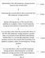
- FIG. 10 shows a schematic flowchart of an in-warehouse control method according to Embodiment 2 of the present disclosure.
- the in-warehouse control method is applied in the warehousing apparatus of claim 1.
- the in-warehouse control method includes:
- the temporary storage position may be arranged on the temporary storage layer board 120 of the shelf 100, the storage position may be arranged on the storage layer board 130 of the shelf, and the temporary storage position and the storage position may be arranged on different layers in the same shelf 100, or may also be arranged on different layers of adjacent shelves.
- the temporary storage position and the storage position may be adjusted and selected according to actual needs, and the arrangement manner of the temporary storage position and the storage position is not limited in the embodiment of the present disclosure.
- the target storage position of the target cargo may be determined according to the type of the target cargo. For example, in a case that the type of the target cargo is the type of the most popular cargo, a storage position with the shortest transfer consuming time may be allocated for the target cargo from the shelf as the target storage position. For example, in a case that the temporary storage position is arranged on the bottom layer of the shelf, a storage position closest to the docking platform and located at a layer above the layer where the temporary storage position is located is the storage position with the shortest transfer consuming-time. In this way, a corresponding consuming-time storage position may be determined as the target storage position according to a popular degree of the target cargo.
- the second robot may be immediately instructed to transfer the target cargo from the target temporary storage position to the target storage position in a case that the transfer completion signal sent by the first robot is received, or the second robot may be instructed to transfer the target cargo from the target temporary storage position to the target storage position after the second robot has completed other operations.
- the first robot and the second robot may use the temporary storage position to independently transfer the target cargo, and the first robot and the second robot can drive high-efficiently with no need to directly cooperate to transfer the target cargo, which improves the in-warehouse efficiency of the cargoes.
- the target temporary storage positions may be determined for the target storage positions of the plurality of target cargoes respectively, and the plurality of first robots are instructed to transfer the plurality of target cargoes to the corresponding target temporary storage positions respectively.
- the second robot is instructed to transfer the plurality of target cargoes from the corresponding target temporary storage positions to the corresponding target storage positions respectively.
- the target temporary storage position is determined based on the target storage position of the target cargo, and the first robot is instructed to transfer the target cargo to the target temporary storage position for temporary storage and the second robot is instructed to transfer the target cargo from the target temporary storage position to the target storage position respectively, so as to separate the ground transfer of the target cargo from the transfer of the target cargo between the temporary storage position and the storage position, so that the first robot may independently complete the ground transfer of the target cargo, and the second robot may independently complete transfer of the target cargo between the temporary storage position and the storage position.
- the first robot may be a robot that accesses and transfers one box of cargoes once, which drives faster and costs less; and the second robot may be a robot that accesses and transfers a plurality of boxes of cargoes once, which drives slower and costs more. If the first robot is directly instructed to transfer the target cargo from the docking platform to the target storage position, and/or the second robot is instructed to transfer the target cargo from the docking platform to the target storage position, both the first robot and the second robot may have lower transfer efficiency and higher transfer costs due to long transfer distances.
- the first robot may transfer cargoes between the docking platform and the temporary storage position
- the second robot may transfer cargoes between the temporary storage position and the storage position, which is beneficial to shorten the driving distances of the first robot and the second robot, so as to improve the in-warehouse efficiency of the cargoes through high-efficient cooperation of the first robot and the second robot.
- the operation S1001: the determining the target temporary storage position according to the target storage position of the target cargo, may include:
- the temporary storage position provided by the temporary storage board 122 under the target storage position provided by the storage board 131 is in an occupied state, it may be determined that the temporary storage position provided by the temporary storage board 123 or the temporary storage position provided by the temporary storage board 124 in an adjacent column of the target storage board 131 is the first idle temporary storage position, and the first robot is instructed to drive towards the first idle temporary storage position; if the temporary storage position provided by the temporary storage position 122 is updated to an idle state during the driving process of the first robot, and a time for the first robot to drive to the first idle temporary storage position is greater than the first preset time threshold, it is determined that the temporary storage position provided by the temporary storage position 122 is the second idle temporary storage position, which is set to the target temporary storage position.
- the target temporary storage position may be dynamically adjusted during the driving process of the first robot, so that the transfer distance between the target temporary storage position and the target storage position is less than the transfer distance between the first idle temporary storage position and the target temporary storage position, which may reduce the transfer distance of the target cargo and improve the in-warehouse efficiency of the cargo.
- the storage positions on both sides of the channel between adjacent shelves may share a set of temporary storage positions, that is, the target storage position and the target temporary storage position may be located on two adjacent shelves respectively.
- the first idle temporary storage position may be the fifth temporary storage position 415 of the first shelf 410, and may also be the fifth temporary storage position 425 of the second shelf 420.
- the storage positions located on both sides of the second robot driving channel 440 may share the temporary storage position on the first shelf 410.
- the update of the temporary storage position below the target storage position to the idle state may be triggered by the second robot moving away the cargoes temporarily stored in the temporary storage position.
- the first idle temporary storage position is determined as the target temporary storage position.
- the target temporary storage position may be directly determined according to the target storage position.
- FIG. 12 shows a schematic diagram of a scenario of an ex-warehouse and in-warehouse control methods according to embodiments of the present disclosure, where the line segment with an arrow indicates the first driving channel 430 located on a side of a temporary storage layer board where the target temporary storage position is located (referring to the first driving channel 141 in FIG. 4 ).
- the target temporary storage position is a fifth temporary storage position 415 in the first shelf 410
- the first transfer route 431 is determined from the first driving channel 430, and the first robot 200 is instructed to drive to a lower side of the fifth temporary storage position 415 along the first transfer route 431.
- the first robot channel includes a cargo access channel located below the temporary storage layer board, and the method further includes:
- one second robot may be used to indirectly cooperate with a plurality of first robots to perform ex-warehouse and in-warehouse control of the target cargoes, which may reduce the ex-warehouse and in-warehouse costs of the target cargoes per unit time and may improve the ex-warehouse and in-warehouse efficiency and the ex-warehouse and in-warehouse capacity of the cargoes.
- a driving speed of the first robot is greater than a driving speed of the second robot.
- the first robot usually transfers the target cargo from the target temporary storage position of the shelf to the docking platform
- the second robot usually transfers the target cargo from the current storage position to the target temporary storage position on one side of the shelf, and a distance between the docking platform and the shelf is much greater than the length of the shelf, so by enabling a driving speed of the first robot greater than a driving speed of the second robot, the number of the target cargoes transferred by the second robot to the target temporary storage position may be adapted to the number of target cargoes transferred by the first robot away from the target temporary storage position, so that the transfer efficiency of the second robot is adapted to the transfer efficiency of the first robot, thereby improving the ex-warehouse efficiency of the target cargoes.
- a plurality of first robots may be arranged to cooperate with the second robot, so as to match an ex-warehouse temporary storage flow of the target cargoes with an ex-warehouse storage flow.
- the operation S1302: determining the target temporary storage position according to the position of the second robot may include:
- the fifth temporary storage position 415 of the first shelf 410 may be determined as the first idle temporary storage position of the second robot 300; if the occupancy status of the fourth temporary storage position 414 of the first shelf 410 is updated to idle during the process of the second robot 300 driving towards the first idle temporary storage position, in a case that a time when the second robot 300 drives to the fifth temporary storage position 415 is greater than the second preset time threshold, the fourth temporary storage position 414 is determined to be the second idle temporary storage position closest to the second robot 300, and is determined as the target temporary storage position.
- the target temporary storage position may be dynamically adjusted, so as to reduce the transfer distance of the second robot 300 and improve the ex-warehouse efficiency of the cargoes.
- the update of the temporary storage position below the target storage position to the idle state may be triggered by the first robot transferring away the cargoes temporarily stored in the temporary storage position.
- the first idle temporary storage position is determined as the target temporary storage position, to directly determine the target temporary storage position.
- the instructing the first robot to transfer the target cargo away from the target temporary storage position includes:
- a transfer-away route 432 between the first robot 200 and the fifth temporary storage position 425 of the second shelf 420 is determined according to the position information between the first robot 200 and the target temporary storage position (namely, the fifth temporary storage position 425 of the second shelf), and the first robot 200 is instructed to drive along the transfer-away route 432 to a lower side of the target temporary storage position (namely, the fifth temporary storage position 425 of the second shelf) to transfer the target cargo away from the target temporary storage position.
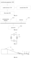
- FIG. 15 shows a structural block diagram of a warehousing system according to Embodiment 4 of the present disclosure.
- the warehousing system 1500 includes: a warehousing apparatus 1000 of any one of the foregoing implementations; a control device 1510, including a processor 1512 and a memory 1511, where the memory 1511 stores instructions, and the instructions, when being loaded and executed by the processor 1512, implement the method of any one of the foregoing implementations; a first robot 200, driving on the first robot channel and having a furcal arm cooperating with a furcal groove; and a second robot 300, driving on the second robot channel.
- the warehousing system of the present invention comprises the features of claim 20.
- the control device further includes: a communication interface 1513, which is used to communicate with an external device and perform data interactive transmission.
- the memory 1511, the processor 1512, and the communication interface 1513 may communicate with each other through an internal interface.
- the foregoing processor may be a central processing unit (CPU), and may also be other general-purpose processors, a digital signal processing (DSP), an application specific integrated circuit (ASIC), a field programmable gate array FPGA) or other programmable logic devices, a discrete gate or transistor logic device, a discrete hardware component, or the like.
- the general-purpose processor may be a microprocessor or any conventional processor. It should be noted that the processor may be a processor supporting the advanced reduced instruction-set computer machine (advanced RISC machines, ARM) architecture.
- the above memory may include a program storage area and a data storage area, where the program storage area may store an operating system, and an application program required for at least one function; and the data storage area may store data created according to the use of the control device and the like.
- the memory may include a high speed random access memory, and may also include a non-transitory memory, such as at least one disk storage device, a flash memory device, or other non-transitory solid state storage devices.
- the memory may optionally include a memory remotely located with respect to the processor, and these remote memories may be connected, via a network, to the control device. Examples of the above networks may include, but are not limited to, the Internet, an intranet, a local area network, a mobile communication network, and combinations thereof.
- Embodiment 5 of the present disclosure further provides a docking platform, applicable to the warehousing apparatus of any one of the foregoing implementations.
- the docking platform will be described below with reference to the accompanying drawings. Said docking platform as such is not a part of the present invention.
- the slope surface 1121 of the slope 1120 of the docking platform 1100 is a plane, and the actuating wheels 913 of the first robot have a relatively small stretching or compressing range relative to the chassis 910, the actuating wheels 913 are substantially coplanar with the front steering wheel 911 and the rear steering wheel 912. In a case that the first robot starts to climb the slope, the front steering wheel 911 of the first robot drive to the slope 1121, and the rear steering wheel 912 drive on the ground 1130.
- the front side of the chassis 910 lifts higher relative to the ground, which is easy to make the actuating wheels 913 hang in the air and unable to exert a grip face on the slope 1121, or the actuating wheels 913 can contact the slope surface 1121 but cannot exert a sufficient grip face on the slope surface 1121 due to the insufficient pressure.
- the slope gradient of the slope 1120 is usually reduced by increasing the length of the slope, which may consume more manufacturing materials and occupy more space, so that there are the problems that the docking platform 1100 has high manufacturing cost and large space occupation.
- Embodiment 2 of the present disclosure provides a docking platform.
- the slope surface of the slope platform along the direction from a slope bottom to a slope top is set as a concave slope surface and a convex slope surface that are smoothly connected to each other, which is beneficial to shorten the length of the slope platform, and may save manufacturing cost and reduce the space occupation.
- FIG. 19A shows a first structural schematic diagram of a docking platform according to Embodiment 5 of the present disclosure
- FIG. 19B shows a top view of a first structural schematic diagram of a docking platform according to Embodiment 5 of the present disclosure
- FIG. 19C shows a side view of a first structural schematic diagram of a docking platform according to Embodiment 5 of the present disclosure.
- the docking platform 1200 may include: a platform body 1210 and a slope platform 1220.
- a slope surface 1220A of the slope platform 1220 includes a concave slope surface 1221 and a convex slope surface 1222 that are arranged in a direction from a slope bottom to a slope top.
- a top edge of the concave slope surface 1221 is smoothly connected to a bottom edge of the convex slope surface 1222; and the slope platform 1220 is arranged on one side of the platform body 1210, so that the slope surface 1220A is smoothly engaged with a top surface 1211 of the platform body 1210.
- the platform body 1210 may have a three-dimensional shape, such as a three-dimensional rectangle or a three-dimensional square.
- the top surface 1211 of the platform body 1210 may form a driving channel of the first robot, for example, the driving channel may be distributed along a length direction of the platform body 1210. Because the platform body 1210 has a specific height, in a case that the first robot drives to the top surface 1211, it is convenient for the user to perform a transit operation on the carried cargoes.
- a height of the platform body 1210 may be selected and adjusted according to actual needs, which is not limited in this embodiment of the present disclosure.
- the slope surface 1220A of the slope platform 1220 includes a concave slope surface 1221 and a convex slope surface 1222 that are arranged in sequence along a direction from a slope bottom to a slope top.
- the top edge of the concave slope surface 1221 is tangent to the bottom edge of the convex slope surface 1222 for smooth connection.
- the bottom edge of the concave slope surface 1221 may be tangent to the ground, so that the slope gradient of the concave slope surface 1221 may be gradually increased from 0°; and the top edge of the convex slope surface 1222 may be tangent to the top surface 1211 of the platform body 1210, so that the slope gradient of the convex slope surface 1222 is gradually reduced to 0°.
- the concave slope surface 1221 is located on a side of a slope bottom side of the slope platform 1220 and is concave toward the bottom surface 1220B of the slope platform 1220.
- the slope gradient of the concave slope surface 1221 gradually increases from 0 along the direction from a slope bottom to a slope top, and increases to a preset slope gradient value at the top of the concave slope surface 1221.
- a tangent value of the concave slope surface 1221 increases gradually along a vertical height direction of the concave slope surface 1221.
- the slope gradient of the slope platform 1220 near the side of the slope bottom may be gradually increased, which is beneficial to shorten the length of the slope platform 1220 on the side of the slope bottom and save the manufacturing cost.
- the convex slope surface 1222 is located on a side of the slope top of the slope platform 1220 and protrudes in a direction away from the bottom surface 1220B of the slope platform 1220.
- the slope gradient of the convex slope surface 1222 gradually decreases from a preset slope gradient value along the direction from a slope bottom to a slope top, and is smoothly engaged with the top surface 1211 of the slope platform 1220 at the top of the convex slope surface 1222.
- a tangent value of the convex slope surface 1222 decreases gradually along a vertical height direction of the convex slope surface 1222.
- the concave slope surface 1221, the convex slope surface 1222, and the platform body 1210 may be smoothly transitioned, so that the first robot may drive smoothly on the slope platform 1220 and the platform body 1210; and the length of the slope platform 1220 on the side of the slope top may also be shortened to save manufacturing cost.
- the concave slope surface 1221 may reduce a lifting height of a front side of the chassis 910 relative to the ground 410 to prevent the actuating wheels 913 from being lifted excessively, so that the actuating wheels 913 can apply an actuating force to the concave slope surface 1221 and prevent the actuating wheels 913 from slipping.
- the actuating wheels 913 slightly stretch the suspension mechanism, so that the centers of the actuating wheels 913 are slightly moved downward relative to the chassis 910, and the actuating wheels 913 can exert the sufficient actuating force on the concave slope surface 1221 to actuate the first robot to drive towards the convex slope surface 1222.
- the centers of the actuating wheels 913 gradually move toward a direction close to the chassis 910, and starts to compress the suspension mechanism; and in a case that both the front steering wheel 911 and the rear steering wheel 912 of the first robot are driving on the convex slope surface 1222, the actuating wheels 913 slightly compress the suspension mechanism, so that the actuating wheels 913 can exert the sufficient actuating force on the convex slope surface 1222 to actuate the first robot to drive towards the platform body 1210.
- the centers of the actuating wheels 913 gradually move toward the direction close to the chassis 910 under the elastic force of the suspension mechanism. Since the convex slope surface 1222 is smoothly engaged with the top surface 1211 of the platform body 1210, it may be avoided that the actuating wheels 913 cannot apply the sufficient actuating force to the convex slope surface 1222 due to the excessive compression of the suspension mechanism.
- a projection of the concave slope surface 1221 in the vertical direction is a first arc (referring to the concave slope surface 1221 in FIG. 19C ), and a projection of the convex slope surface 1222 in the vertical direction is the second arc (referring to the convex slope surface 1222 in FIG. 19C ); and an arc radius of the first arc is greater than or equal to an arc radius of the second arc.
- the arc radius of the first arc may be between 8000 mm to 10700 mm
- the arc radius of the second arc may be between 500 mm to 2832 mm
- the arc radiuses of the first arc and the second arc may be selected and adjusted according to actual needs, which is not limited in this embodiment of the present disclosure.
- the slope gradient of the concave slope surface 1221 may be the same as the slope gradient of the convex slope surface 1222, or the slope gradient of the concave slope surface 1221 is gentler than the slope gradient of the convex slope surface 1222, which is beneficial for the first robot to drive smoothly along the concave slope surface 1221 and the convex slope surface 1222.
- a length of a first arc is equal to or greater than a length of a second arc.
- the length of the first arc and the length of the second arc may be selected and adjusted according to actual needs, which are not limited in this embodiment of the present disclosure.
- the docking platform 1200 may further include a plurality of support pads 1230, and the plurality of support pads 1230 are arranged at the bottom of the slope platform 1220 at an interval along the length direction of the slope platform 1220.
Landscapes
- Engineering & Computer Science (AREA)
- Mechanical Engineering (AREA)
- Robotics (AREA)
- Quality & Reliability (AREA)
- General Engineering & Computer Science (AREA)
- Manufacturing & Machinery (AREA)
- Physics & Mathematics (AREA)
- General Physics & Mathematics (AREA)
- Automation & Control Theory (AREA)
- Human Computer Interaction (AREA)
- Warehouses Or Storage Devices (AREA)
- Control By Computers (AREA)
- Radar Systems Or Details Thereof (AREA)
- Selective Calling Equipment (AREA)
- Electrophonic Musical Instruments (AREA)
Description
- The present disclosure claims priority to
Chinese Patent Application No. 202010231552.9, filed with the Chinese Patent Office on March 27, 2020 Chinese Patent Application No. 202021892576.0, filed with the Chinese Patent Office on September 2, 2020 Chinese Patent Application No. 202010231545.9, filed with the Chinese Patent Office on March 27, 2020 Chinese Patent Application No. 202010232310.1, filed with the Chinese Patent Office on March 27, 2020 Chinese Patent Application No. 202022292766.5, filed with the Chinese Patent Office on October 15, 2020 - The present disclosure relates to the field of warehousing technologies, and in particular, to a warehousing apparatus, system, and a control method.
- The existing warehousing industry mostly uses robots integrated with automatic climbing and moving capabilities to access and transfer cargoes. However, because there are too many storage actions for the robots in accessing the cargoes, this leads to low efficiency for in-warehouse and ex-warehouse of the cargoes.
-
CN109987366A relates to an unmanned warehousing system and an in-warehouse and ex-warehouse method. The system comprises two-layered channel supporting frames, in which a lower layer is used as a passage for an automatic vehicle, and an upper layer is used as a passage for a normalized container. Said document discloses a warehousing apparatus according to the preamble of claim 1. - The invention is set out in the appended independent claims. Embodiments of the invention become apparent from the dependent claims.
- The invention provides a warehousing apparatus according to claim 1, an in-warehouse control method according to claim 12, an ex-warehouse control method according to claim 17 and a warehousing system according to claim 20 to solve or alleviate one or more technical problems in the related art.
- The invention has the following advantages or beneficial effects: the first robot directly accesses the cargoes on the temporary storage layer board, which avoids the operation of extending the robot arm to a shelf layer board, and improve the efficiency of accessing cargoes; in addition, the temporary storage layer board may temporarily store the cargoes, and the storage positions provided by the storage layer board may store the cargoes for a long time, which is convenient to cooperate the temporary storage layer board with the storage layer board to improve the ex-warehouse and in-warehouse efficiency of the cargoes; furthermore, the first robot channel and the second robot channel are respectively formed, which can avoid the first robot and the second robot sharing a same driving channel, improve the driving efficiency of the first robot and the second robot, and then improve the ex-warehouse and in-warehouse efficiency.
- To describe the technical solutions in the embodiments of the present invention or the related art more clearly, the following briefly describes the accompanying drawings required for describing the embodiments or the related art.
-
FIG. 1 shows a three-dimensional schematic structural diagram of a warehousing apparatus according to Embodiment 1 of the present disclosure; -
FIG. 2 shows a schematic side view of a warehousing apparatus according to Embodiment 1 of the present disclosure; -
FIG. 3 shows a schematic structural diagram of a warehousing apparatus according to Embodiment 2 of the present disclosure; -
FIG. 4 shows a schematic structural diagram of a shelf according to Embodiment 1 of the present disclosure; -
FIG. 5 shows a schematic structural diagram of a shelf according to Embodiment 1 of the present disclosure; -
FIG. 6 shows a schematic structural diagram of a first robot according to Embodiment 1 of the present disclosure; -
FIG. 7 shows a schematic diagram of cooperation between a furcal arm of a first robot and a furcal groove of a shelf according to Embodiment 1 of the present disclosure; -
FIG. 8 shows a schematic structural diagram of a second robot according to Embodiment 1 of the present disclosure; -
FIG. 9 shows a schematic diagram of an application scenario according to an embodiment of the present disclosure; -
FIG. 10 shows a schematic flowchart of an in-warehouse control method according to Embodiment 2 of the present disclosure; -
FIG. 11 shows a schematic flowchart of the operation S1001 inFIG. 10 ; -
FIG. 12 shows a schematic diagram of an application scenario of ex-warehouse and in-warehouse control according to an embodiment of the present disclosure; -
FIG. 13 shows a schematic flowchart of an ex-warehouse control method according to Embodiment 3 of the present disclosure; -
FIG. 14 shows a schematic flowchart of the operation S1302 inFIG. 13 ; -
FIG. 15 shows a schematic structural diagram of a warehousing system according to Embodiment 4 of the present disclosure; -
FIG. 16 shows a schematic structural diagram of a control device according to Embodiment 4 of the present disclosure; -
FIG. 17 shows a schematic diagram of a layout of steering wheels and actuating wheels of a first robot; -
FIG. 18 shows a schematic diagram of a position between a chassis and a slope in a case that a first robot climbs a slope; -
FIG. 19A shows a first structural schematic diagram of a docking platform according to Embodiment 5 of the present disclosure; -
FIG. 19B shows a top view of a first structural schematic diagram of a docking platform according to Embodiment 5 of the present disclosure; -
FIG. 19C shows a side view of a first structural schematic diagram of a docking platform according to Embodiment 5 of the present disclosure; -
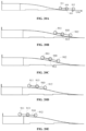
FIG. 20A shows a first schematic diagram of a state of a first robot driving along a slope platform to a platform body according to Embodiment 5 of the present disclosure; -
FIG. 20B shows a second schematic diagram of a state of a first robot driving along a slope platform to a platform body according to Embodiment 5 of the present disclosure; -
FIG. 20C shows a third schematic diagram of a state of a first robot driving along a slope platform to a platform body according to Embodiment 5 of the present disclosure; -
FIG. 20D shows a fourth schematic diagram of a state of a first robot driving along a slope platform to a platform body according to Embodiment 5 of the present disclosure; -
FIG. 20E shows a fifth schematic diagram of a state of a first robot driving along a slope platform to a platform body according to Embodiment 5 of the present disclosure; -
FIG. 21 shows a second structural schematic diagram of a docking platform according to Embodiment 5 of the present disclosure; -
FIG. 22 shows a third structural schematic diagram of a docking platform according to Embodiment 5 of the present disclosure; and -
FIG. 23 shows a schematic structural diagram of a workstation according to Embodiment 5 of the present disclosure. - Only some exemplary embodiments are briefly described below.
-
FIG. 1 shows a three-dimensional schematic structural diagram of a warehousing apparatus according to an embodiment of the present disclosure. - As shown in
FIG. 1 to FIG. 4 , according to the invention, thewarehousing apparatus 1000 includes at least one temporarystorage layer board 120, where the temporarystorage layer board 120 is used to provide at least one temporary storage position; a plurality ofshelves 100, where each of theshelves 100 include at least onestorage layer board 130 and a plurality ofcolumns 110 arranged at an interval in a horizontal direction, and thestorage layer board 130 is used to provide at least one storage position. The temporarystorage layer board 120 is provided withfurcal grooves 121, and each of thefurcal grooves 121 is used to cooperate with afurcal arm 210 of thefirst robot 200; and thestorage layer board 130 is arranged at an interval with the temporarystorage layer board 120 in a vertical direction through thecolumns 110. - In an example, the plurality of
shelves 100 may be single-row shelves, double-row shelves or multi-row shelves; the number of the plurality ofshelves 100 include two or more; and the plurality ofshelves 100 may be arranged in columns (refer toFIG. 1 and FIG. 2 ), in rows (refer toFIG. 3 ), or in a matrix. The number of rows of, the number of, and the arrangement manner of the plurality ofshelves 100 may be selected and adjusted according to actual needs, and both the number of and the arrangement manner of the plurality ofshelves 100 are not limited in the embodiment of the present disclosure. - In an example, the plurality of
columns 110 may enclose a rectangular area in which the temporarystorage layer board 120 and thestorage layer board 130 are installed, so that the temporarystorage layer board 120 and thestorage layer board 130 are arranged at an interval in the vertical direction through thecolumns 110. However, arrangement positions of thecolumns 110 are not limited in this embodiment, as long as the temporarystorage layer board 120 and thestorage layer board 130 may be arranged at an interval in the vertical direction. For example, thecolumns 110 may also pass through the middle of the temporarystorage layer board 120 and thestorage layer board 130 in the vertical direction, instead of an edge thereof. - For ease of description, in the following embodiment, a long side of the temporary
storage layer board 120 is set as a side of the temporarystorage layer board 120, and a short side of the temporarystorage layer board 120 is set as an end of the temporarystorage layer board 120. - In an example, a plurality of temporary storage positions provided on the temporary
storage layer board 120 includes two or more temporary storage positions; afurcal groove 121 is arranged under each temporary storage position, and the shape of thefurcal groove 121 may be U-shaped, C-shaped, I-shaped, V-shaped, or the like. The shape of thefurcal groove 121 may be selected and adjusted according to actual needs, as long as it can cooperate with thefurcal arm 210 of thefirst robot 200, and the shape of thefurcal groove 121 is not limited in the present disclosure. - The temporary
storage layer board 120 may be located on any layer of theshelf 100, and the position of the temporarystorage layer board 120 is not limited in the embodiment of the present disclosure. In a case that the temporarystorage layer board 120 is located in a middle layer of theshelf 100, thestorage layer boards 130 are located above and below the temporarystorage layer board 120, which may shorten distances between the temporarystorage layer board 120 and thestorage layer boards 130, and improve the transfer efficiency of the cargoes between the temporarystorage layer board 120 and thestorage layer boards 130. The cargoes may be boxes containing materials, products, and the like. The boxes may be cardboard boxes or material boxes, and the type of the boxes and the articles contained therein are not limited in the present disclosure. - In an example, the width of the temporary
storage layer board 120 is less than half of the width of thestorage layer board 130. For example, theshelf 100 may be a double-row shelf, the temporarystorage layer board 120 may be one row of the double-row shelf, thestorage layer board 130 extends from one row to another row of the double-row shelf in the horizontal direction, and the width of the temporarystorage layer board 120 is set to be less than half of the width of thestorage layer board 130. Since a width channel of the cargoes is greater than the width of thefirst robot 200, the width of the temporarystorage layer board 120 is set to be less than half of the width of thestorage layer board 130, the width of thefirst driving channel 141 may be greater than the width of thestorage layer board 130, to provide a channel wide enough for thefirst robot 200 to transfer cargoes; and because the width of thestorage layer board 130 is greater than twice width of the temporarystorage layer board 120, thestorage layer board 130 may store a cargo whose size is slightly larger than that of the temporary storage position. - The
warehousing apparatus 1000 includes:
a first robot channel for thefirst robot 200 to drive, where thefirst robot 200 is used to cooperate with thefurcal groove 121 through thefurcal arm 210 thereof to access the cargoes on the temporarystorage layer board 120; and a second robot channel for thesecond robot 300 to drive, where thesecond robot 300 is used to transfer cargoes between the temporarystorage layer board 120 and thestorage layer board 130. - In an example, the first robot channel may be defined by the structure of the
shelf 100. The second robot channel may be located on another side outside theshelf 100, so as to separate the first robot channel from the second robot channel to avoid channel occupation. - As shown in
FIG. 6 andFIG. 7 , thefirst robot 200 may be an AGV (Automated Guided Vehicle, AGV for short) vehicle with thefurcal arm 210, and thefurcal arm 210 thereof may be arranged on the top of thefirst robot 200, and may also be arranged on the side of thefirst robot 200. The arrangement manner of thefurcal arm 210 of thefirst robot 200 is not limited in the embodiment of the present disclosure. - As shown in
FIG. 8 , thesecond robot 300 may be the AGV vehicle with alifting mechanism 320 and anaccess mechanism 330, or may also be a stacking machine, or the like. The type of thesecond robot 300 is not limited in the embodiment of the present disclosure, as long as it has the functions of accessing and transferring cargoes. According to thewarehousing apparatus 1000 of the embodiment of the present disclosure, since the temporarystorage layer board 120 provides thefurcal groove 121 for cooperating with thefurcal arm 210 of thefirst robot 200, thefurcal arm 210 of thefirst robot 200 may be directly inserted into thefurcal groove 121 of the temporarystorage layer board 120, so that thefirst robot 200 may directly access the cargoes on the temporarystorage layer board 120, which avoids the operation of extending the robot arm to theshelf 100, and improves the efficiency of accessing cargoes; in addition, the temporarystorage layer board 120 may temporarily store the cargoes, and the storage positions provided by thestorage layer board 130 may store the cargoes for a long time, which is convenient to cooperate the temporarystorage layer board 120 with thestorage layer board 130 to improve the ex-warehouse and in-warehouse efficiency of the cargoes; furthermore, the first robot channel and the second robot channel are respectively formed, which can further avoid thefirst robot 200 and thesecond robot 300 sharing a same driving channel, improve the driving efficiency of thefirst robot 200 and thesecond robot 300, and then improve the ex-warehouse and in-warehouse efficiency. - In an implementation, the first robot channel may include a
cargo access channel 140, and thecargo access channel 140 is located below the temporarystorage layer board 120. In a case that thefirst robot 200 is in thecargo access channel 140, thefurcal groove 121 cooperates with thefurcal arm 210 on thefirst robot 200 to access the cargoes. - In an example, as shown in
FIG. 4 andFIG. 7 , in a case of storing the cargoes, thefirst robot 200 aligns thefurcal arm 210 with thefurcal groove 121 at the side of the furcal groove of the temporarystorage layer board 120 and drives to thecargo access channel 140, so that thefurcal arm 210 directly protrudes into thefurcal groove 121, and the cargoes are placed on the temporarystorage layer board 120, and then thefurcal arm 210 is lowered so that the cargo box is left on the temporarystorage layer board 120; and in a case of picking up cargoes, thefirst robot 200 drives below thecargo access channel 140, aligns thefurcal arm 210 with thefurcal groove 121 below the temporarystorage layer board 120 and lifts thefurcal arm 210 to jack up the cargo box, and then drives in a direction away from the side of the furcal groove of the temporarystorage layer board 120 to leave thecargo access channel 140 to take the cargo box. In this way, thefirst robot 200 may directly pick up the cargoes without stopping driving or stopping driving for a short time, eliminating the operation of controlling the robot arm to extend to the layer board, which may improve the efficiency of accessing the cargo box, and accessing and obtaining is performed below the temporarystorage layer board 120, which may effectively utilize the space of theshelf 100. - In an implementation, the cargo access channel may further be used for the first robot to drive in a case that the first robot is unloaded.
- In an example, in a case that the
first robot 200 is unloaded (namely, thefirst robot 200 is not loaded with cargoes), thefirst robot 200 may directly drive in thecargo access channel 140, which may improve the transfer efficiency of the cargoes. - In an implementation, as shown in
FIG. 4 , thecolumns 110 are arranged on the outer periphery of thestorage layer board 130, the first robot channel includes afirst driving channel 141, and thefirst driving channel 141 is located between the temporarystorage layer board 120 and thecolumns 110 located on the side of the furcal groove of the temporarystorage layer board 120. - In an example, in a case that the temporary
storage layer board 120 is located at the bottom layer of thecolumns 110, the temporarystorage layer board 120, thecolumns 110 located on the side of the furcal groove of the temporarystorage layer board 120, and the ground may form afirst driving channel 141 for thefirst robot 200 to drive. - In an example, in a case that the temporary
storage layer board 120 is located at other layers other than the bottom layer of thecolumns 110, the temporarystorage layer board 120, thecolumns 110 located on the side of the furcal groove of the temporarystorage layer board 120, and astorage layer board 130 located on a layer below and next to the layer where the temporarystorage layer board 120 is located may form afirst driving channel 141 for thefirst robot 200 to drive. - In this implementation, the
first driving channel 141 for thefirst robot 200 to drive is formed between the temporarystorage layer board 120 and thecolumns 110 located on the side of the furcal groove of the temporarystorage layer board 120, so that thefirst robot 200 may drive in any layer of theshelf 100, which is convenient for thefirst robot 200 to cooperate with the temporarystorage layer board 120 and avoids occupying a channel outside theshelf 100. - In an example, as shown in
FIG. 4 , theshelf 100 may further include: crossbeams 150, where each of the cross beams 150 is arranged in a horizontal direction and is used for fixing short sides of the temporarystorage layer board 120 and thestorage layer board 130 on thecolumns 110. -
FIG. 5 shows a schematic structural diagram of ashelf 100 according to another embodiment of the present disclosure. The structure of theshelf 100 is similar to the structure of theshelf 100 inFIG. 1 , the difference is that, as shown inFIG. 5 , asecond driving channel 142 for thefirst robot 200 to drive is formed between the temporarystorage layer board 120 and thecolumns 110 located at the first end of the temporarystorage layer board 120. In this way, thefirst robot 200 may pass through theshelf 100 in thesecond driving channel 142, so that a driving distance of thefirst robot 200 may be shortened, and transfer efficiency of cargo boxes may be improved. - In an example, the
shelf 100 may further include: asupport column 160 arranged at the first end of the temporarystorage layer board 120 for support. - In an implementation, as shown in
FIG. 1 to FIG. 4 , the temporarystorage layer board 120 includes a plurality of temporary storage boards, each of the temporary storage boards is provided with afurcal groove 121, and a third driving channel for thefirst robot 200 to drive is formed between at least two temporary storage boards (refer to 143 inFIG. 9 ). In this way, thefirst robot 200 may pass through theshelf 100 between any two temporary storage boards of the temporarystorage layer board 120, so that a driving distance of thefirst robot 200 may be shortened, and transfer efficiency of cargo boxes may be improved. - In this embodiment, as shown in
FIG. 9 , thesecond robot channel 310 is formed betweenadjacent shelves 100, so that thesecond robot 300 may drive in thesecond robot channel 310, so as to transfer cargoes between the temporarystorage layer board 120 and thestorage layer board 130. The cargoes temporarily stored in the temporarystorage layer board 120 are transferred to thestorage layer board 130 for in-warehouse storage, or the cargoes stored in thestorage layer board 130 are transferred to the temporarystorage layer board 120 for the ex-warehouse temporary storage, which may improve the access efficiency and the ex-warehouse and in-warehouse efficiency of the cargoes; in addition, thesecond robot channel 310 does not coincide with the driving channel of thefirst robot 200, which may avoid thefirst robot 200 and thesecond robot 300 sharing a same driving channel, improve the cooperation efficiency of thefirst robot 200 and thesecond robot 300, and then improve the ex-warehouse and in-warehouse efficiency. - It should be noted that, in the
warehousing apparatus 1000, thesecond robot 300 integrated with alifting mechanism 320 and anaccess mechanism 330 is generally used to transfer and access cargoes. However, because the cost of thesecond robot 300 is relatively high, and there are relatively long distances between adocking port 400 for the cargoes and each temporary storage position and each storage position in theshelf 100, the ex-warehouse and in-warehouse costs of the cargoes per unit time are relatively high, and the efficiency is relatively low. By forming thesecond robot channel 310 betweenadjacent shelves 100, thewarehousing apparatus 1000 of the embodiment of the present disclosure may be configured with thesecond robot 300 to transfer cargoes between the temporarystorage layer board 120 and thestorage layer board 130, and may be configured with thefirst robot 200 to transfer and access the cargoes on the temporarystorage layer board 120, where thefirst robot 200 may not have a lifting mechanism, and the cost thereof is much lower than that of thesecond robot 300. In this way, onesecond robot 300 may be equipped with a plurality offirst robots 200 for coordinating access of cargoes, which may reduce the ex-warehouse and in-warehouse costs of the cargoes per unit time and may improve the ex-warehouse and in-warehouse efficiency of the cargoes. - In an application scenario, the
first robot 200 may be a robot that accesses and transfers one box of cargoes once, and thesecond robot 300 may be a robot that accesses and transfers a plurality of boxes of cargoes once. Thesecond robot 300 is configured to transfer cargoes between the temporarystorage layer board 120 and thestorage layer board 130, and thefirst robot 200 is configured to transfer and access cargoes on the temporarystorage layer board 120, which may reduce the ex-warehouse and in-warehouse costs of the cargoes per unit time and may improve the ex-warehouse and in-warehouse efficiency of the cargoes. - In an implementation, as shown in
FIG. 9 , the temporary storage layer board includes a plurality of temporary storage boards, and each of the temporary storage boards is provided with a furcal groove. The first robot channel includes athird driving channel 143, and thethird driving channel 143 is located between at least two temporary storage boards. A width of thethird driving channel 143 may be one, two, three, or more times the width of the temporary storage board, which is not limited in the present disclosure. For example, some of the temporary storage boards may be removed to form thethird driving channel 143. In this way, thefirst robot 200 may pass through the shelf in thethird driving channel 143 to improve the driving efficiency. - In an implementation, as shown in
FIG. 9 , the first robot channel includes a fourth driving channel 144, the fourth driving channel 144 is located between twoadjacent shelves 100 and connects twothird driving channels 143 or twosecond driving channels 142. In this way, thefirst robot 200 may pass through theshelf 100 via thethird driving channel 143 and then drives along the fourth driving channel 144 to anadjacent shelf 100, thereby shortening a driving distance of thefirst robot 200 and improving the transfer efficiency of the cargoes. - In an implementation, the
warehousing apparatus 1000 further includes a docking platform 400 (thedocking platform 400 may also be referred to as a docking port). Asecond driving channel 142 for thefirst robot 200 to drive is formed between the temporarystorage layer board 120 and thecolumns 110 at the first end of the temporarystorage layer board 120, and afifth driving channel 145 for thefirst robot 200 to drive is formed between thedocking platform 400 and theshelf 100. For example, afifth driving channel 145 for thefirst robot 200 to drive is formed between thedocking platform 400 and thecolumns 110 located at the second end of the temporarystorage layer board 120. In this way, thefirst robot 200 may directly drive from thedocking platform 400 to thefirst driving channel 141 of thefirst robot 200 in theshelf 100 along thefifth driving channel 145, and can quickly reach the temporarystorage layer board 120, thereby improving the cooperation efficiency. - In an example, the
fifth driving channel 145, thefirst driving channel 141, thesecond driving channel 142, thethird driving channel 143, and the fourth driving channel 144 may form a first driving loop for thefirst robot 200 to drive (a line segment loop with arrows inFIG. 9 ). - In an example, the
cargo access channel 140 below the temporarystorage layer board 120 may form a second driving loop (a dashed line with arrows inFIG. 9 ) for thefirst robot 200 to drive, so that thefirst robot 200 drives in a case of being unloaded. - In an example, the
second robot channel 310 of thesecond robot 300 may form a loop (a dotted line with arrows inFIG. 9 ) for thesecond robot 300 to drive. - By arranging the first driving loop, the second driving loop, and the loop for the
second robot 300 to drive in the foregoing examples, thefirst robot 200 and thesecond robot 300 may be prevented from occupying each other's driving channel, thereby improving the cooperation efficiency between the two. In this way, a plurality offirst robots 200 and a plurality ofsecond robots 300 may be arranged to implement the ex-warehouse and in-warehouse of the cargoes and improve the ex-warehouse and in-warehouse efficiency. -
FIG. 10 shows a schematic flowchart of an in-warehouse control method according to Embodiment 2 of the present disclosure. According to the invention, the in-warehouse control method is applied in the warehousing apparatus of claim 1. As shown inFIG. 10 , the in-warehouse control method includes: - S1001: determining a target temporary storage position according to a target storage position of a target cargo;
- S1002: instructing a first robot to transfer the target cargo to the target temporary storage position; and
- S1003: in a case that a transfer completion signal sent by the first robot is received, instructing a second robot to transfer the target cargo from the target temporary storage position to the target storage position, where the target storage position and the target temporary storage position are arranged in different layers.
- As shown in
FIG. 4 , the temporary storage position may be arranged on the temporarystorage layer board 120 of theshelf 100, the storage position may be arranged on thestorage layer board 130 of the shelf, and the temporary storage position and the storage position may be arranged on different layers in thesame shelf 100, or may also be arranged on different layers of adjacent shelves. The temporary storage position and the storage position may be adjusted and selected according to actual needs, and the arrangement manner of the temporary storage position and the storage position is not limited in the embodiment of the present disclosure. - The target storage position of the target cargo may be determined according to the type of the target cargo. For example, in a case that the type of the target cargo is the type of the most popular cargo, a storage position with the shortest transfer consuming time may be allocated for the target cargo from the shelf as the target storage position. For example, in a case that the temporary storage position is arranged on the bottom layer of the shelf, a storage position closest to the docking platform and located at a layer above the layer where the temporary storage position is located is the storage position with the shortest transfer consuming-time. In this way, a corresponding consuming-time storage position may be determined as the target storage position according to a popular degree of the target cargo.
- In an example, since the target temporary storage position may temporarily store the target cargo, the second robot may be immediately instructed to transfer the target cargo from the target temporary storage position to the target storage position in a case that the transfer completion signal sent by the first robot is received, or the second robot may be instructed to transfer the target cargo from the target temporary storage position to the target storage position after the second robot has completed other operations. In this way, the first robot and the second robot may use the temporary storage position to independently transfer the target cargo, and the first robot and the second robot can drive high-efficiently with no need to directly cooperate to transfer the target cargo, which improves the in-warehouse efficiency of the cargoes.
- In an example, according to the in-warehouse control method, the target temporary storage positions may be determined for the target storage positions of the plurality of target cargoes respectively, and the plurality of first robots are instructed to transfer the plurality of target cargoes to the corresponding target temporary storage positions respectively. In a case that the transfer completion signals sent by the plurality of first robots is received, the second robot is instructed to transfer the plurality of target cargoes from the corresponding target temporary storage positions to the corresponding target storage positions respectively.
- According to the in-warehouse control method of the embodiment of the present disclosure, the target temporary storage position is determined based on the target storage position of the target cargo, and the first robot is instructed to transfer the target cargo to the target temporary storage position for temporary storage and the second robot is instructed to transfer the target cargo from the target temporary storage position to the target storage position respectively, so as to separate the ground transfer of the target cargo from the transfer of the target cargo between the temporary storage position and the storage position, so that the first robot may independently complete the ground transfer of the target cargo, and the second robot may independently complete transfer of the target cargo between the temporary storage position and the storage position. There is no need for the first robot and the second robot to directly dock the target cargo, which avoids a phenomenon that the first robot and the second robot wait for each other, and helps improve the in-warehouse efficiency of the cargoes.
- In an application scenario, the first robot may be a robot that accesses and transfers one box of cargoes once, which drives faster and costs less; and the second robot may be a robot that accesses and transfers a plurality of boxes of cargoes once, which drives slower and costs more. If the first robot is directly instructed to transfer the target cargo from the docking platform to the target storage position, and/or the second robot is instructed to transfer the target cargo from the docking platform to the target storage position, both the first robot and the second robot may have lower transfer efficiency and higher transfer costs due to long transfer distances. However, according to the in-warehouse control method of the embodiment of the present disclosure, the first robot may transfer cargoes between the docking platform and the temporary storage position, and the second robot may transfer cargoes between the temporary storage position and the storage position, which is beneficial to shorten the driving distances of the first robot and the second robot, so as to improve the in-warehouse efficiency of the cargoes through high-efficient cooperation of the first robot and the second robot.
- For example, as shown in
FIG. 11 , the operation S1001: the determining the target temporary storage position according to the target storage position of the target cargo, may include: - S1101: determining a first idle temporary storage position closest to the target storage position;
- S1102: instructing the first robot to drive toward the first idle temporary storage position;
- S1103: during a driving process of the first robot, updating an occupancy status of each temporary storage position based on a preset time interval;
- S1104: in a case that a time when the first robot drives to the first idle temporary storage position is greater than a first preset time threshold, determining whether there is a second idle temporary storage position closest to the target storage position according to an updated occupancy status of each temporary storage position; and
- S1105: in a case that there is the second idle temporary storage position, determining the second idle temporary storage position as the target temporary storage position.
- In an example, as shown in
FIG. 4 , in a case that the temporary storage position provided by thetemporary storage board 122 under the target storage position provided by thestorage board 131 is in an occupied state, it may be determined that the temporary storage position provided by the temporary storage board 123 or the temporary storage position provided by thetemporary storage board 124 in an adjacent column of thetarget storage board 131 is the first idle temporary storage position, and the first robot is instructed to drive towards the first idle temporary storage position; if the temporary storage position provided by thetemporary storage position 122 is updated to an idle state during the driving process of the first robot, and a time for the first robot to drive to the first idle temporary storage position is greater than the first preset time threshold, it is determined that the temporary storage position provided by thetemporary storage position 122 is the second idle temporary storage position, which is set to the target temporary storage position. In this way, the target temporary storage position may be dynamically adjusted during the driving process of the first robot, so that the transfer distance between the target temporary storage position and the target storage position is less than the transfer distance between the first idle temporary storage position and the target temporary storage position, which may reduce the transfer distance of the target cargo and improve the in-warehouse efficiency of the cargo. - It should be noted that the storage positions on both sides of the channel between adjacent shelves may share a set of temporary storage positions, that is, the target storage position and the target temporary storage position may be located on two adjacent shelves respectively. For example, as shown in
FIG. 12 , in a case that the target storage position is located above or below the fifthtemporary storage position 415 of thefirst shelf 410, the first idle temporary storage position may be the fifthtemporary storage position 415 of thefirst shelf 410, and may also be the fifthtemporary storage position 425 of thesecond shelf 420. In this way, the storage positions located on both sides of the secondrobot driving channel 440 may share the temporary storage position on thefirst shelf 410. - The update of the temporary storage position below the target storage position to the idle state may be triggered by the second robot moving away the cargoes temporarily stored in the temporary storage position.
- In an implementation, in a case that there is not the second idle temporary storage position, the first idle temporary storage position is determined as the target temporary storage position. In this way, the target temporary storage position may be directly determined according to the target storage position.
- In an implementation, the instructing the first robot to transfer the target cargo to the target temporary storage position, includes:
- determining a first transfer route from the preset first robot channel according to position information between the first robot and the target temporary storage position, where the first robot channel includes a first driving channel located on one side of the temporary storage layer board where the target temporary storage position is located, and the first driving channel is located in a vertical projection area of the storage layer board where the target storage position is located; and
- instructing the first robot to drive to a lower side of the target temporary storage position along the first transfer route.
- In an example, as shown in
FIG. 12, FIG. 12 shows a schematic diagram of a scenario of an ex-warehouse and in-warehouse control methods according to embodiments of the present disclosure, where the line segment with an arrow indicates the first driving channel 430 located on a side of a temporary storage layer board where the target temporary storage position is located (referring to thefirst driving channel 141 inFIG. 4 ). In a case that the target temporary storage position is a fifthtemporary storage position 415 in thefirst shelf 410, thefirst transfer route 431 is determined from the first driving channel 430, and thefirst robot 200 is instructed to drive to a lower side of the fifthtemporary storage position 415 along thefirst transfer route 431. In this way, thefirst robot 200 may drive in the preset first driving channel 430, so as to prevent thefirst robot 200 from occupying the driving channel of thesecond robot 300, and improve the driving efficiency between thefirst robot 200 and thesecond robot 300, thereby improving the in-warehouse efficiency. - In an implementation, the instructing the second robot to transfer the target cargo from the target temporary storage position to the target storage position, includes:
- determining a second transfer route from a preset second robot channel according to position information between the second robot and the target temporary storage position, where the second robot channel is located outside a vertical projection area; and
- instructing the second robot to drive to a side of the target temporary storage position along the second transfer route.
- In an example, as shown in
FIG. 12 , the second robot channel 440 (a dotted line with arrows) may be located outside the vertical projection area of the shelf. In a case that thesecond robot 300 is located at a side of the secondtemporary storage position 412 of thefirst shelf 410, the second transfer route 441 between the side of the secondtemporary storage position 412 and the side of the fifthtemporary storage position 415 is determined according to the position information between thesecond robot 300 and the target temporary storage position (namely, the fifth temporary storage position 415), and thesecond robot 300 is instructed to drive along the second transfer route 441 to the side of the fifthtemporary storage position 415 to take out the target cargo from the fifthtemporary storage position 415. - In an implementation, the second driving channel is formed at one end of the temporary storage layer board. The temporary storage layer board includes a plurality of temporary storage boards for providing temporary storage positions, a third driving channel is formed between at least two of the temporary storage boards, and the first robot channel includes a second driving channel and a third driving channel.
- In an example, as shown in
FIG. 12 , one end of thefirst shelf 410 away from thedocking platform 400 is formed with asecond driving channel 142. There is a third driving channel (not marked in the figure) between the fifthtemporary storage position 415 and the sixthtemporary storage position 416 of thefirst shelf 410, and between the eighthtemporary storage position 418 and the ninth temporary storage position 419 of thefirst shelf 410, and then thefirst robot 200 may determine a driving route from the third driving channel, and plan a shorter driving route for thefirst robot 200, improving the driving efficiency of thefirst robot 200. - In an implementation, the first robot channel includes a cargo access channel located below the temporary storage layer board, and the method further includes:
- in a case that the first robot is unloaded, determining an unloaded driving route from the first robot channel; and
- instructing the first robot to drive along the unloaded driving route.
- In an example, as shown in
FIG. 12 , the first robot channel includes acargo access channel 450 located below the temporary storage layer board (referring to thecargo access channel 140 of theshelf 100 inFIG. 4 ), namely, the dashed line with the arrow inFIG. 4 . In a case that the first robot is unloaded (namely, the first robot does not carry cargoes), the first robot may drive in the first driving channel 430, the second driving channel, and thecargo access channel 450. -
FIG. 13 shows a schematic flowchart of an ex-warehouse control method according to Embodiment 3 of the present disclosure. According to the invention, the ex-warehouse control method is applied in the warehousing apparatus according to claim 1. As shown inFIG. 13 , the ex-warehouse control method includes: - S1301: instructing a second robot to transfer a target cargo away from a current storage position;
- S1302: determining a target temporary storage position according to a position of the second robot, where the current storage position and the target temporary storage position are arranged in different layers;
- S1303: instructing the second robot to transfer the target cargo to the target temporary storage position; and
- S1304: in a case that a transfer completion signal sent by the second robot is received, instructing the first robot to transfer the target cargo away from the target temporary storage position.
- A setting manner of the temporary storage position and the storage position in the ex-warehouse control method may be the same as the setting manner thereof in the in-warehouse control method, and the setting manner of the temporary storage position and the storage position is not repeated herein again.
- The current storage position of the target cargo may be determined according to identification information of the target cargo in an ex-warehouse list. For example, a relationship mapping table between the current storage position of the target cargo and the identification information of the target cargo may be stored in advance. In a case that the identification information of the target cargo is obtained from the ex-warehouse list, the current storage position of the target cargo may be queried from the relationship mapping table. The current storage position of the target cargo may also be determined in other ways, and the determining manner of the current storage position of the target cargo is not limited in the embodiments of the present disclosure.
- In an example, since the target temporary storage position may temporarily store the target cargo, in a case that the transfer completion signal sent by the second robot is received, the first robot may be immediately instructed to transfer the target cargo away from the target temporary storage position, or the first robot may be also instructed to transfer the target cargo away from the target temporary storage position after the first robot has completed other operations. In this way, the first robot and the second robot may use the temporary storage position to independently transfer the target cargo, and the first robot and the second robot can drive high-efficiently with no need to directly cooperate to transfer the target cargo, which can improve the ex-warehouse efficiency of the cargoes.
- In an example, according to the ex-warehouse control method, the second robot may be instructed to transfer the plurality of target cargoes away from the current storage positions of the plurality of target cargoes respectively, and corresponding target temporary storage positions are respectively determined according to the position of the second robot, and the second robot is instructed to transfer the target cargo to a corresponding target temporary storage position. In this way, the plurality of target cargoes may be transferred to the corresponding target temporary storage positions.
- According to the ex-warehouse control method of the embodiment of the present disclosure, the target temporary storage position is determined based on the position of the second robot, and the second robot is instructed to transfer the target cargo to the target temporary storage position and the first robot is instructed to transfer the target cargo away from the target temporary storage position respectively, so as to separate the transfer of the target cargo between the temporary storage position and the storage position from the ground transfer of the target cargo, so that the second robot may independently complete the transfer of the target cargo between the storage position and the temporary storage position, and the first robot may independently complete transfer of the target cargo away from the target temporary storage position. There is no need for the first robot and the second robot to directly dock the target cargo, which avoids a phenomenon that the first robot and the second robot wait for each other, and helps improve the ex-warehouse efficiency of the cargoes.
- It should be noted that a robot integrated with a lifting mechanism and an access mechanism is usually used in the ex-warehouse and in-warehouse control methods to transfer and access cargoes; however, due to the high cost of such the robot, and there are relatively long distances between a docking platform for the cargoes and each temporary storage position and each storage position in the shelf, the ex-warehouse and in-warehouse costs of the cargoes per unit time are relatively high, and the efficiency is relatively low.
- According to the ex-warehouse and in-warehouse control methods of the embodiments of the present disclosure, the ground transfer of the target cargoes is separated from the transfer of the target cargoes between the temporary storage position and the storage position, so that the first robot may concentrate on completing the ground transfer of the target cargoes, and the second robot may concentrate on completing the transfer of the target cargoes between the temporary storage position and the storage position, where the first robot may not have a lifting mechanism, and the cost thereof is much lower than that of the second robot. In this way, one second robot may be used to indirectly cooperate with a plurality of first robots to perform ex-warehouse and in-warehouse control of the target cargoes, which may reduce the ex-warehouse and in-warehouse costs of the target cargoes per unit time and may improve the ex-warehouse and in-warehouse efficiency and the ex-warehouse and in-warehouse capacity of the cargoes.
- In an implementation, a driving speed of the first robot is greater than a driving speed of the second robot.
- Because in the ex-warehouse control, the first robot usually transfers the target cargo from the target temporary storage position of the shelf to the docking platform, and the second robot usually transfers the target cargo from the current storage position to the target temporary storage position on one side of the shelf, and a distance between the docking platform and the shelf is much greater than the length of the shelf, so by enabling a driving speed of the first robot greater than a driving speed of the second robot, the number of the target cargoes transferred by the second robot to the target temporary storage position may be adapted to the number of target cargoes transferred by the first robot away from the target temporary storage position, so that the transfer efficiency of the second robot is adapted to the transfer efficiency of the first robot, thereby improving the ex-warehouse efficiency of the target cargoes.
- In an example, according to the in-warehouse control method, a plurality of first robots may be arranged to cooperate with the second robot, so as to match an ex-warehouse temporary storage flow of the target cargoes with an ex-warehouse storage flow.
- For example, as shown in
FIG. 14 , the operation S1302: determining the target temporary storage position according to the position of the second robot, may include: - S1401: determining a first idle temporary storage position closest to the second robot;
- S1402: instructing the second robot to drive toward the first idle temporary storage position;
- S1403: during a driving process of the second robot, updating an occupancy status of each temporary storage position based on a preset time interval;
- S1404: in a case that a time when the second robot drives to the first idle temporary storage position is greater than a second preset time threshold, determining whether there is a second idle temporary storage position closest to the second robot according to an updated occupancy status of each temporary storage position; and
- S1405: in a case that there is the second idle temporary storage position, determining the second idle temporary storage position as the target temporary storage position.
- In an example, as shown in
FIG. 12 , in a case that thesecond robot 300 is located on one side of the secondtemporary storage position 412 of thefirst shelf 410, the fifthtemporary storage position 415 of thefirst shelf 410 may be determined as the first idle temporary storage position of thesecond robot 300; if the occupancy status of the fourth temporary storage position 414 of thefirst shelf 410 is updated to idle during the process of thesecond robot 300 driving towards the first idle temporary storage position, in a case that a time when thesecond robot 300 drives to the fifthtemporary storage position 415 is greater than the second preset time threshold, the fourth temporary storage position 414 is determined to be the second idle temporary storage position closest to thesecond robot 300, and is determined as the target temporary storage position. In this way, during the process of thesecond robot 300 transferring the target cargoes, the target temporary storage position may be dynamically adjusted, so as to reduce the transfer distance of thesecond robot 300 and improve the ex-warehouse efficiency of the cargoes. - The update of the temporary storage position below the target storage position to the idle state may be triggered by the first robot transferring away the cargoes temporarily stored in the temporary storage position.
- In an implementation, in a case that there is not the second idle temporary storage position, the first idle temporary storage position is determined as the target temporary storage position, to directly determine the target temporary storage position.
- In an implementation, the instructing the first robot to transfer the target cargo away from the target temporary storage position, includes:
- determining a transfer-away route from the preset first robot channel according to position information between the first robot and the target temporary storage position, where the first robot channel includes a first driving channel located on one side of the temporary storage layer board where the target temporary storage position is located, and the first driving channel is located in a vertical projection area of the storage layer board where the target storage position is located; and
- instructing the first robot to drive to a lower side of the target temporary storage position along the transfer-away route.
- In an example, as shown in
FIG. 12 , in a case that thefirst robot 200 is located in a position near the eighthtemporary storage position 428 in the first driving channel of thesecond shelf 420, and the target temporary storage position is the fifthtemporary storage position 425 of thesecond shelf 420, a transfer-away route 432 between thefirst robot 200 and the fifthtemporary storage position 425 of thesecond shelf 420 is determined according to the position information between thefirst robot 200 and the target temporary storage position (namely, the fifthtemporary storage position 425 of the second shelf), and thefirst robot 200 is instructed to drive along the transfer-away route 432 to a lower side of the target temporary storage position (namely, the fifthtemporary storage position 425 of the second shelf) to transfer the target cargo away from the target temporary storage position. -
FIG. 15 shows a structural block diagram of a warehousing system according to Embodiment 4 of the present disclosure. As shown inFIG. 15 and FIG. 16 , the warehousing system 1500 includes: awarehousing apparatus 1000 of any one of the foregoing implementations; acontrol device 1510, including aprocessor 1512 and amemory 1511, where thememory 1511 stores instructions, and the instructions, when being loaded and executed by theprocessor 1512, implement the method of any one of the foregoing implementations; afirst robot 200, driving on the first robot channel and having a furcal arm cooperating with a furcal groove; and asecond robot 300, driving on the second robot channel. The warehousing system of the present invention comprises the features of claim 20. - In an implementation, a driving speed of the
first robot 200 is greater than a driving speed of thesecond robot 300. -
FIG. 16 shows a structural block diagram of a control device according to Embodiment 4 of the present disclosure. As shown inFIG. 16 , thecontrol device 1510 includes: amemory 1511 and aprocessor 1512, where a computer program executable on theprocessor 1512 is stored in thememory 1511. Theprocessor 1512, when executing the computer program, implements the in-warehouse control method and the ex-warehouse control method in the foregoing embodiments. There may be one ormore memories 1511 andprocessors 1512. Said control device is not a part of the present invention. - The control device further includes: a
communication interface 1513, which is used to communicate with an external device and perform data interactive transmission. - If the
memory 1511, theprocessor 1512, and thecommunication interface 1513 are independently implemented, thememory 1511, theprocessor 1512, and thecommunication interface 1513 may be connected to each other through a bus and communicate with each other. The bus may be an Industry Standard Architecture (ISA) bus, a Peripheral Component Interconnect (PCI) bus, an Extended Industry Standard Architecture (EISA) bus, or the like. The bus may include an address bus, a data bus, a control bus, and the like. For ease of representation, only one thick line is used to represent the bus inFIG. 16 , but it does not mean that there is only one bus or one type of bus. - Optionally, in a specific implementation, if the
memory 1511, theprocessor 1512, and thecommunication interface 1513 are integrated on one chip, thememory 1511, theprocessor 1512, and thecommunication interface 1513 may communicate with each other through an internal interface. - The foregoing processor may be a central processing unit (CPU), and may also be other general-purpose processors, a digital signal processing (DSP), an application specific integrated circuit (ASIC), a field programmable gate array FPGA) or other programmable logic devices, a discrete gate or transistor logic device, a discrete hardware component, or the like. The general-purpose processor may be a microprocessor or any conventional processor. It should be noted that the processor may be a processor supporting the advanced reduced instruction-set computer machine (advanced RISC machines, ARM) architecture.
- Optionally, the above memory may include a program storage area and a data storage area, where the program storage area may store an operating system, and an application program required for at least one function; and the data storage area may store data created according to the use of the control device and the like. In addition, the memory may include a high speed random access memory, and may also include a non-transitory memory, such as at least one disk storage device, a flash memory device, or other non-transitory solid state storage devices. In some embodiments, the memory may optionally include a memory remotely located with respect to the processor, and these remote memories may be connected, via a network, to the control device. Examples of the above networks may include, but are not limited to, the Internet, an intranet, a local area network, a mobile communication network, and combinations thereof.
- Embodiment 5 of the present disclosure further provides a docking platform, applicable to the warehousing apparatus of any one of the foregoing implementations. The docking platform will be described below with reference to the accompanying drawings. Said docking platform as such is not a part of the present invention.
- As shown in
FIG. 17 , achassis 910 of the first robot (the first robot may be referred to as a transfer robot) is usually provided with afront steering wheel 911, arear steering wheel 912, and actuatingwheels 913, where thefront steering wheel 911 and therear steering wheel 912 are respectively arranged at the front and rear positions of thechassis 910 to change a driving direction of the first robot; and the actuatingwheels 913 are arranged on both sides of thechassis 910 and are connected to thechassis 910 through a suspension mechanism (not shown in the figure), to provide an actuating force for the first robot. In a case that the first robot drives to a hogwallow, the actuatingwheels 913 may stretch the suspension mechanism; and in a case that the first robot drives to a raised ground, the actuatingwheels 913 may compress the suspension mechanism to buffer the impact on the body of the first robot caused by the uneven ground. It should be noted that, in order to simplify the drawings, in the embodiment of the present disclosure, thefront steering wheel 911, therear steering wheel 912, the actuatingwheels 913, and thechassis 910 of the first robot are used to illustrate the driving of the first robot. - As shown in
FIG. 18 , since theslope surface 1121 of theslope 1120 of thedocking platform 1100 is a plane, and the actuatingwheels 913 of the first robot have a relatively small stretching or compressing range relative to thechassis 910, the actuatingwheels 913 are substantially coplanar with thefront steering wheel 911 and therear steering wheel 912. In a case that the first robot starts to climb the slope, thefront steering wheel 911 of the first robot drive to theslope 1121, and therear steering wheel 912 drive on theground 1130. If theslope 1120 has a relatively large slope gradient, the front side of thechassis 910 lifts higher relative to the ground, which is easy to make theactuating wheels 913 hang in the air and unable to exert a grip face on theslope 1121, or the actuatingwheels 913 can contact theslope surface 1121 but cannot exert a sufficient grip face on theslope surface 1121 due to the insufficient pressure. This causes theactuating wheels 913 of the first robot to slip, so that the first robot cannot drive along theslope 1120 to theplatform body 1110. In order to enable theactuating wheels 913 of the first robot to exert the sufficient grip face on theslope surface 1121 of theslope 1120, the slope gradient of theslope 1120 is usually reduced by increasing the length of the slope, which may consume more manufacturing materials and occupy more space, so that there are the problems that thedocking platform 1100 has high manufacturing cost and large space occupation. - Based on this, Embodiment 2 of the present disclosure provides a docking platform. The slope surface of the slope platform along the direction from a slope bottom to a slope top is set as a concave slope surface and a convex slope surface that are smoothly connected to each other, which is beneficial to shorten the length of the slope platform, and may save manufacturing cost and reduce the space occupation.
-
FIG. 19A shows a first structural schematic diagram of a docking platform according to Embodiment 5 of the present disclosure,FIG. 19B shows a top view of a first structural schematic diagram of a docking platform according to Embodiment 5 of the present disclosure, andFIG. 19C shows a side view of a first structural schematic diagram of a docking platform according to Embodiment 5 of the present disclosure. - As shown in FIG. 15A to FIG. 15C, the
docking platform 1200 may include: aplatform body 1210 and aslope platform 1220. Aslope surface 1220A of theslope platform 1220 includes aconcave slope surface 1221 and aconvex slope surface 1222 that are arranged in a direction from a slope bottom to a slope top. A top edge of theconcave slope surface 1221 is smoothly connected to a bottom edge of theconvex slope surface 1222; and theslope platform 1220 is arranged on one side of theplatform body 1210, so that theslope surface 1220A is smoothly engaged with atop surface 1211 of theplatform body 1210. - For example, the
platform body 1210 may have a three-dimensional shape, such as a three-dimensional rectangle or a three-dimensional square. Thetop surface 1211 of theplatform body 1210 may form a driving channel of the first robot, for example, the driving channel may be distributed along a length direction of theplatform body 1210. Because theplatform body 1210 has a specific height, in a case that the first robot drives to thetop surface 1211, it is convenient for the user to perform a transit operation on the carried cargoes. A height of theplatform body 1210 may be selected and adjusted according to actual needs, which is not limited in this embodiment of the present disclosure. - In an example, the
slope surface 1220A of theslope platform 1220 includes aconcave slope surface 1221 and aconvex slope surface 1222 that are arranged in sequence along a direction from a slope bottom to a slope top. The top edge of theconcave slope surface 1221 is tangent to the bottom edge of theconvex slope surface 1222 for smooth connection. - Optionally, also referring to
FIG. 20A , the bottom edge of theconcave slope surface 1221 may be tangent to the ground, so that the slope gradient of theconcave slope surface 1221 may be gradually increased from 0°; and the top edge of theconvex slope surface 1222 may be tangent to thetop surface 1211 of theplatform body 1210, so that the slope gradient of theconvex slope surface 1222 is gradually reduced to 0°. - Specifically, the
concave slope surface 1221 is located on a side of a slope bottom side of theslope platform 1220 and is concave toward thebottom surface 1220B of theslope platform 1220. The slope gradient of theconcave slope surface 1221 gradually increases from 0 along the direction from a slope bottom to a slope top, and increases to a preset slope gradient value at the top of theconcave slope surface 1221. In other words, a tangent value of theconcave slope surface 1221 increases gradually along a vertical height direction of theconcave slope surface 1221. In this way, the slope gradient of theslope platform 1220 near the side of the slope bottom may be gradually increased, which is beneficial to shorten the length of theslope platform 1220 on the side of the slope bottom and save the manufacturing cost. - The
convex slope surface 1222 is located on a side of the slope top of theslope platform 1220 and protrudes in a direction away from thebottom surface 1220B of theslope platform 1220. The slope gradient of theconvex slope surface 1222 gradually decreases from a preset slope gradient value along the direction from a slope bottom to a slope top, and is smoothly engaged with thetop surface 1211 of theslope platform 1220 at the top of theconvex slope surface 1222. In other words, a tangent value of theconvex slope surface 1222 decreases gradually along a vertical height direction of theconvex slope surface 1222. In this way, theconcave slope surface 1221, theconvex slope surface 1222, and theplatform body 1210 may be smoothly transitioned, so that the first robot may drive smoothly on theslope platform 1220 and theplatform body 1210; and the length of theslope platform 1220 on the side of the slope top may also be shortened to save manufacturing cost. - Also referring to
FIG. 19C andFIG. 20A , during the process of the first robot driving along theslope platform 1220 to theplatform body 1210, in a case that thefront steering wheel 911 of the first robot drives to theconcave slope surface 1221, and therear steering wheel 912 are still driving on theground 410, theconcave slope surface 1221 may reduce a lifting height of a front side of thechassis 910 relative to theground 410 to prevent theactuating wheels 913 from being lifted excessively, so that the actuatingwheels 913 can apply an actuating force to theconcave slope surface 1221 and prevent theactuating wheels 913 from slipping. - Also referring to
FIG. 19C andFIG. 20B , in a case that both thefront steering wheel 911 and therear steering wheel 912 of the first robot are driving on theconcave slope surface 1221, the actuatingwheels 913 slightly stretch the suspension mechanism, so that the centers of the actuatingwheels 913 are slightly moved downward relative to thechassis 910, and the actuatingwheels 913 can exert the sufficient actuating force on theconcave slope surface 1221 to actuate the first robot to drive towards theconvex slope surface 1222. - Also referring to
FIG. 19C ,FIG. 20C, and FIG. 20D , in a case that the actuatingwheels 913 of the first robot actuate thefront steering wheel 911 to drive on theconvex slope surface 1222 and drive therear steering wheel 912 to drive from theconcave slope surface 1221 to theconvex slope surface 1222, the centers of the actuatingwheels 913 gradually move toward a direction close to thechassis 910, and starts to compress the suspension mechanism; and in a case that both thefront steering wheel 911 and therear steering wheel 912 of the first robot are driving on theconvex slope surface 1222, the actuatingwheels 913 slightly compress the suspension mechanism, so that the actuatingwheels 913 can exert the sufficient actuating force on theconvex slope surface 1222 to actuate the first robot to drive towards theplatform body 1210. - Also referring to
FIG. 19C andFIG. 20E , in a case that the actuatingwheels 913 of the first robot actuate thefront steering wheel 911 to drive on theplatform body 1210 and drive therear steering wheel 912 to drive from theconvex slope surface 1222 to theplatform body 1210, the centers of the actuatingwheels 913 gradually move toward the direction close to thechassis 910 under the elastic force of the suspension mechanism. Since theconvex slope surface 1222 is smoothly engaged with thetop surface 1211 of theplatform body 1210, it may be avoided that the actuatingwheels 913 cannot apply the sufficient actuating force to theconvex slope surface 1222 due to the excessive compression of the suspension mechanism. - In an embodiment, referring to
FIG. 19C , a projection of theconcave slope surface 1221 in the vertical direction is a first arc (referring to theconcave slope surface 1221 inFIG. 19C ), and a projection of theconvex slope surface 1222 in the vertical direction is the second arc (referring to theconvex slope surface 1222 inFIG. 19C ); and an arc radius of the first arc is greater than or equal to an arc radius of the second arc. For example, the arc radius of the first arc may be between 8000 mm to 10700 mm, the arc radius of the second arc may be between 500 mm to 2832 mm, and the arc radiuses of the first arc and the second arc may be selected and adjusted according to actual needs, which is not limited in this embodiment of the present disclosure. - In this embodiment, by setting the arc radius of the first arc to be greater than or equal to the arc radius of the second arc, the slope gradient of the
concave slope surface 1221 may be the same as the slope gradient of theconvex slope surface 1222, or the slope gradient of theconcave slope surface 1221 is gentler than the slope gradient of theconvex slope surface 1222, which is beneficial for the first robot to drive smoothly along theconcave slope surface 1221 and theconvex slope surface 1222. - In an implementation, a length of a first arc is equal to or greater than a length of a second arc. The length of the first arc and the length of the second arc may be selected and adjusted according to actual needs, which are not limited in this embodiment of the present disclosure.
- In an implementation, as shown in
FIG. 19A and FIG. 19C , thedocking platform 1200 may further include a plurality ofsupport pads 1230, and the plurality ofsupport pads 1230 are arranged at the bottom of theslope platform 1220 at an interval along the length direction of theslope platform 1220. - In an example, the
slope platform 1220 and the plurality ofsupport pads 1230 may be an integral piece or separate pieces; if theslope platform 1220 and the plurality ofsupport pads 1230 are separate pieces, theslope platform 1220 and the plurality ofsupport pads 1230 may be combined into an integral piece. - In an example, there may be three
support pads 1230, and the threesupport pads 1230 are respectively disposed on a front side, a middle position, and a rear side of the bottom of theslope platform 1220. - In this implementation, a plurality of
support pads 1230 are arranged at the bottom of theslope platform 1220 along the length direction of theslope platform 1220 at an interval, so that theslope platform 1220 may be elevated and an arch portion may be formed betweenadjacent support pads 1230. In this way, the bottom of thesupport pads 1230 may be contacted with the ground to reduce a contact area between the bottom of theslope platform 1220 and the ground, to prevent theslope platform 1220 from shaking due to uneven ground, so that theslope platform 1220 can be placed on the ground stably. - In an implementation, as shown in
FIG. 19A to FIG. 19C , thedocking platform 1200 may further include abaffle plate 1240. Thebaffle plate 1240 is arranged on the top of theplatform body 1210 and located on the side of theplatform body 1210 away from theslope platform 1220. For example, thebaffle plate 1240 may be arranged on a side of thetop surface 1211 of theplatform body 1210 away from theslope platform 1220. Thebaffle plate 1240 and theplatform body 1210 may be an integral piece or separate pieces. Thebaffle plate 1240 may be arranged to protect the first robot and prevent the first robot from falling from the side of theplatform body 1210 away from theslope platform 1220. - In an implementation, as shown in
FIG. 21 , a side wall of theplatform body 1210 opposite to theslope platform 1220 is provided with aclamping groove 1410, and a side wall of theslope platform 1220 opposite to theplatform body 1210 is provided with a clamping strip (not shown in the figure), and the clamping strip is clamped in theclamping groove 1410, so that theslope platform 1220 is clamped with theplatform body 1210. - In this implementation, the clamping
groove 1410 is arranged on theplatform body 1210 and the clamping strip is arranged on theslope platform 1220, so that theplatform body 1210 and theslope platform 1220 may be clamped into an integral piece, which is convenient for assembly, disassembly, transportation, storage, and the like. It may be understood that theplatform body 1210 and theslope platform 1220 may also be set as an integral piece according to actual needs, and an arrangement form of theplatform body 1210 and theslope platform 1220 is not limited in this embodiment of the present disclosure. - In an implementation, the clamping
groove 1410 is arranged along the length direction of theplatform body 1210, and the clamping strip is arranged along the width direction of theslope platform 1220; there are at least twoslope platforms 1220, and the clamping strips of two of theslope platforms 1220 is slidable along the clampinggroove 1410 to adjust a spacing. - In an example, the clamping
groove 1410 is arranged along the length direction of theplatform body 1210 and is located on the side wall opposite to theslope platform 1220; the clamping strip is arranged along the width direction of theslope platform 1220 and is located on the side wall opposite to theplatform body 1210; the clamping strip is slidable along the clampinggroove 1410, and may adjust the position of theslope platform 1220 on theplatform body 1210 to improve the flexibility of an assembly position of theslope platform 1220. - In an example, a driving track label of the first robot may be set on the ground, and in a case that there are at least two
slope platforms 1220, the clamping strips of theslope platforms 1220 slides along the clampinggroove 1410 of theplatform body 1210 to adjust the spacing between theslope platforms 1220, so as to align theslope platforms 1220 with the driving track label, so that the first robot can drive to theslope platform 1220 along the driving track label. In addition, the spacing between theslope platforms 1220 may also be adjusted according to a size of the cargo carried by the first robot, so that the spacing between theslope platforms 1220 is adapted to the size of the cargo. It should be noted that the number of theslope platforms 1220 may be selected and adjusted according to actual needs, and the number of theslope platforms 1220 is not limited in the present disclosure. - In an implementation, as shown in
FIG. 19B and FIG. 19C , thetop surface 1211 of theplatform body 1210 forms a driving channel, andslope surfaces 1220A of the twoslope platforms 1220 respectively form a drive-in channel and a drive-out channel; tops of the drive-in channel and the drive-out channel are respectively connected to the driving channels (lines with arrows in the figure show driving directions of the drive-in channel, the driving channel, and the drive-out channel). In this way, the first robot may drive along the drive-in channel to the driving channel on theplatform body 1210, and drive along the driving channel to the drive-out channel, and then drive out the drive-out channel, which can improve the efficiency of cargo carrying and transit. - In an example, there are three
slope platforms 1220, slope surfaces 1220A of two of theslope platforms 1220 may be set as two drive-in channels, and aslope surface 1220A of theother slope platform 1220 is set as the drive-out channel. The tops of the drive-in channels and the drive-out channel are respectively connected to the driving channel. The number of the drive-in and drive-out channels may be selected and adjusted according to actual needs, which is not limited in this embodiment of the present disclosure. - In an implementation, the width of the
platform body 1210 is greater than the width of theslope platform 1220, so that the first robot transfers a cargo with a larger size on theplatform body 1210. - In an implementation, as shown in
FIG. 19A to FIG. 19C andFIG. 22 , aplatform bracket 1511 adapted to the shape of theplatform body 1210 is arranged inside theplatform body 1210, and aslope bracket 1521 adapted to the shape of theslope platform 1220 is arranged inside theslope platform 1220. - In an example, the
platform bracket 1511 is provided with aplatform support plate 1512 to form theplatform body 1210; and theslope bracket 1521 is provided with aslope support plate 1522 to form theslope platform 1220. -
FIG. 23 shows a schematic structural diagram of a workstation according to Embodiment 5 of the present disclosure. As shown inFIG. 23 , theworkstation 1600 may include: a plurality ofdocking platforms 1200 according to any one of the foregoing implementations, and the plurality ofdocking platforms 1200 are arranged along the length direction of theplatform body 1210, so thattop surfaces 1211 of the plurality ofplatform bodies 1210 are engaged. In this way, it is convenient for the first robot to drive along thetop surfaces 1211 of the plurality ofplatform bodies 1210, and a drive-in channel and a drive-out channel may also be flexibly configured. - Other components of the
docking platform 1200 and theworkstation 1600 in the foregoing embodiments may adopt various technical solutions known to those of ordinary skill in the art now and in the future, which will not be described in detail herein. - According to the
docking platform 1200 and theworkstation 1600 of the present disclosure, theslope surface 1220A of theslope platform 1220 is set as theconcave slope surface 1221 and theconvex slope surface 1222 along the direction from a slope bottom to a slope top, and theconcave slope surface 1221 is smoothly connected to theconvex slope surface 1222, and theslope surface 1220A is smoothly engaged with thetop surface 1211 of theplatform body 1210, which is beneficial to shorten the length of theslope platform 1220, and may reduce the manufacturing cost and space occupation.
Claims (20)
- A warehousing apparatus, comprising:a temporary storage layer board (120), wherein the temporary storage layer board (120) is used to provide a temporary storage position;a plurality of shelves (100), wherein each of the shelves (100) comprises at least one storage layer board (130) and a plurality of columns (110) arranged at an interval in a horizontal direction, the storage layer board (130) is used to provide a storage position, and the storage layer board (130) is arranged at an interval with the temporary storage layer board (120) in a vertical direction through the columns (110);a first robot channel for a first robot (200) to drive, wherein the first robot (200) is used to access a cargo on the temporary storage layer board (120); anda second robot channel for a second robot (300) to drive, wherein the second robot (300) is used to transfer the cargo between the temporary storage layer board (120) and the storage layer board (130),wherein the columns (110) are arranged on a periphery of the storage layer board (130), wherein the first robot channel comprises a first driving channel (141), characterized in that the first driving channel (141) is disposed between the temporary storage layer board (120) and the columns (110),wherein the temporary storage layer board (120) is provided with furcal grooves (121), and each of the furcal grooves (121) is used to cooperate with a furcal arm (210) of the first robot (200).
- The warehousing apparatus of claim 1, wherein the first robot channel comprises a cargo access channel and the cargo access channel is located below the temporary storage layer board (120).
- The warehousing apparatus of claim 2, wherein the cargo access channel is further used for the first robot (200) to drive in a case that the first robot (200) is unloaded.
- The warehousing apparatus of claim 1, wherein the first robot channel comprises a second driving channel, and the second driving channel is located between the temporary storage layer board (120) and a column (110) located at a first end of the temporary storage layer board (120).
- The warehousing apparatus of claim 4, wherein the temporary storage layer board (120) comprises a plurality of temporary storage boards for providing the temporary storage position, the first robot channel comprises a third driving channel, and the third driving channel is located between at least two of the temporary storage boards.
- The warehousing apparatus of claim 5, wherein the first robot channel comprises a fourth driving channel; the fourth driving channel is located between two adjacent shelves (100), and connects two third driving channels or two second driving channels.
- The warehousing apparatus of any one of claims 1 to 6, wherein the second robot channel is located on a periphery of the shelves (100) and comprises a channel between adjacent shelves (100).
- The warehousing apparatus of any one of claims 1 to 6, wherein the temporary storage layer board (120) is arranged on the shelves (100).
- The warehousing apparatus of claim 8, further comprising a docking platform (400), wherein the first robot channel comprises a fifth driving channel, the fifth driving channel is located between the docking platform (400) and the shelves (100), and the docking platform (400) comprises:a platform body (1210); anda slope platform (1220), wherein a slope surface (1220A) of the slope platform (1220) comprises a concave slope surface (1221) and a convex slope surface (1222) that are arranged in a direction from a slope bottom to a slope top, and a top edge of the concave slope surface (1221) is smoothly connected to a bottom edge of the convex slope surface (1222);wherein the slope platform (1220) is arranged on one side of the platform body (1210), so that the slope surface (1220A) is smoothly engaged with a top surface of the platform body (1210).
- The warehousing apparatus of claim 9, wherein a projection of the concave slope surface (1221) in the vertical direction is a first arc, a projection of the convex slope surface (1222) in the vertical direction is a second arc, and an arc radius of the first arc is greater than or equal to an arc radius of the second arc.
- The warehousing apparatus of claim 9, wherein a side wall of the platform body (1210) opposite to the slope platform (1220) is provided with a clamping groove, a side wall of the slope platform (1220) opposite to the platform body (1210) is provided with a clamping strip, and the clamping strip is clamped in the clamping groove, so that the slope platform (1220) is clamped with the platform body (1210); the clamping groove is arranged along a length direction of the platform body (1210), and the clamping strip is arranged along a width direction of the slope platform (1220); there are at least two slope platforms (1210), and clamping strips of two of the slope platforms (1210) is slidable along the clamping groove to adjust a spacing.
- An in-warehouse control method in a warehousing apparatus according to any one of the claims 1-11, comprising:determining (S1001) a target temporary storage position according to a target storage position of a target cargo;instructing (S1002) a first robot (200) to transfer the target cargo to the target temporary storage position; andin a case that a transfer completion signal sent by the first robot is received, instructing (S1003) a second robot (300) to transfer the target cargo from the target temporary storage position to the target storage position.
- The method of claim 12, wherein the determining (S1001) the target temporary storage position according to the target storage position of the target cargo, comprises:determining (S1101) a first idle temporary storage position closest to the target storage position;instructing (S1102) the first robot (200) to drive toward the first idle temporary storage position;during (S1103) a driving process of the first robot, updating an occupancy status of each temporary storage position based on a preset time interval;in a case that a time when the first robot drives to the first idle temporary storage position is greater than a first preset time threshold, determining (S1104) whether there is a second idle temporary storage position closest to the target storage position according to an updated occupancy status of each temporary storage position; andin a case that there is the second idle temporary storage position, determining (S1105) the second idle temporary storage position as the target temporary storage position.
- The method of claim 12, wherein the instructing (S1002) the first robot (200) to transfer the target cargo to the target temporary storage position, comprises:determining a first transfer route from the first robot channel according to position information between the first robot and the target temporary storage position; andinstructing the first robot to drive to a lower side of the target temporary storage position along the first transfer route.
- The method of claim 14, wherein the first robot channel comprises a cargo access channel located below the temporary storage layer board, and the method further comprises:in a case that the first robot (200) is unloaded, determining an unloaded driving route from the first robot channel; andinstructing the first robot to drive along the unloaded driving route.
- The method of claim 12, wherein the instructing (S1003) the second robot (300) to transfer the target cargo from the target temporary storage position to the target storage position, comprises:determining a second transfer route from the second robot channel according to position information between the second robot and the target temporary storage position; andinstructing the second robot to drive to a side of the target temporary storage position along the second transfer route.
- An ex-warehouse control method in a warehousing apparatus according to any one of the claims 1-11, comprising:instructing (S1301) a second robot (300) to transfer a target cargo away from a current storage position;determining (S1302) a target temporary storage position according to a position of the second robot;instructing (S1303) the second robot to transfer the target cargo to the target temporary storage position; andin a case that a transfer completion signal sent by the second robot is received, instructing (S1304) the first robot (200) to transfer the target cargo away from the target temporary storage position.
- The method of claim 17, wherein the determining (S1302) the target temporary storage position according to the position of the second robot (300), comprises:determining (S1401) a first idle temporary storage position closest to the second robot;instructing (S1402) the second robot to drive toward the first idle temporary storage position;during (S1403) a driving process of the second robot, updating an occupancy status of each temporary storage position based on a preset time interval;in a case that a time when the second robot drives to the first idle temporary storage position is greater than a second preset time threshold, determining (S1404) whether there is a second idle temporary storage position closest to the second robot according to an updated occupancy status of each temporary storage position; andin a case that there is the second idle temporary storage position, determining (S1405) the second idle temporary storage position as the target temporary storage position.
- The method of claim 17, wherein the instructing (S1304) the first robot (200) to transfer the target cargo away from the target temporary storage position, comprises:determining a first transfer route from the first robot channel according to position information between the first robot and the target temporary storage position; andinstructing the first robot to drive to a lower side of the target temporary storage position along the first transfer route.
- A warehousing system, comprising:the warehousing apparatus (1000) of any one of claims 1 to 11;a control device (1510), comprising a processor (1512) and a memory (1511), wherein the memory stores instructions, and the instructions, when being loaded and executed by the processor (1512), implement the method of any one of claims 12 to 19;a first robot (200), driving on a first robot channel; anda second robot (300), driving on a second robot channel.
Applications Claiming Priority (6)
| Application Number | Priority Date | Filing Date | Title |
|---|---|---|---|
| CN202010232310.1A CN111453275B (en) | 2020-03-27 | 2020-03-27 | Method, device and equipment for controlling warehouse entry and warehouse exit and readable storage medium |
| CN202010231545.9A CN111361908B (en) | 2020-03-27 | 2020-03-27 | Storage device, system and control method |
| CN202010231552.9A CN111232530A (en) | 2020-03-27 | 2020-03-27 | Shelving and Storage Units |
| CN202021892576 | 2020-09-02 | ||
| CN202022292766.5U CN213651054U (en) | 2020-10-15 | 2020-10-15 | Docking platform and workstation |
| PCT/CN2021/070888 WO2021190084A1 (en) | 2020-03-27 | 2021-01-08 | Storage device and system and control method |
Publications (4)
| Publication Number | Publication Date |
|---|---|
| EP4074627A1 EP4074627A1 (en) | 2022-10-19 |
| EP4074627A4 EP4074627A4 (en) | 2024-02-07 |
| EP4074627C0 EP4074627C0 (en) | 2025-06-25 |
| EP4074627B1 true EP4074627B1 (en) | 2025-06-25 |
Family
ID=77890921
Family Applications (2)
| Application Number | Title | Priority Date | Filing Date |
|---|---|---|---|
| EP21776149.3A Active EP4105147B1 (en) | 2020-03-27 | 2021-01-08 | Temporary storage shelf board, goods shelf, control method and warehousing system |
| EP21776624.5A Active EP4074627B1 (en) | 2020-03-27 | 2021-01-08 | Storage device and system and control method |
Family Applications Before (1)
| Application Number | Title | Priority Date | Filing Date |
|---|---|---|---|
| EP21776149.3A Active EP4105147B1 (en) | 2020-03-27 | 2021-01-08 | Temporary storage shelf board, goods shelf, control method and warehousing system |
Country Status (11)
| Country | Link |
|---|---|
| US (3) | US11702288B2 (en) |
| EP (2) | EP4105147B1 (en) |
| JP (2) | JP7746271B2 (en) |
| KR (1) | KR102946203B1 (en) |
| AU (2) | AU2021240488B2 (en) |
| BR (2) | BR112022019368A2 (en) |
| CA (1) | CA3173140A1 (en) |
| IL (2) | IL296793B2 (en) |
| MX (2) | MX2022011908A (en) |
| SA (1) | SA522440686B1 (en) |
| WO (2) | WO2021190085A1 (en) |
Families Citing this family (13)
| Publication number | Priority date | Publication date | Assignee | Title |
|---|---|---|---|---|
| JP7298589B2 (en) * | 2020-12-15 | 2023-06-27 | 株式会社ダイフク | Goods storage facility |
| AU2022443619B2 (en) * | 2022-02-28 | 2026-03-26 | Beijing Geekplus Technology Co., Ltd. | Object carrying device, transport robot, warehousing system and goods shelf |
| WO2024140053A1 (en) * | 2022-12-27 | 2024-07-04 | 北京极智嘉科技股份有限公司 | Warehousing system and container transfer method |
| DE102023118300A1 (en) * | 2023-07-11 | 2025-01-16 | Kardex Produktion Deutschland Gmbh | Storage device with integrated work area in front of the access area |
| US12459732B2 (en) * | 2023-10-16 | 2025-11-04 | SIMPL Automation Inc. | Load handling system for storage racking |
| CN117416697B (en) * | 2023-11-22 | 2025-10-31 | 豪德数控(湖北)有限公司 | Strip sorting system and sorting method |
| CN117585355A (en) * | 2023-12-28 | 2024-02-23 | 北京京东乾石科技有限公司 | Warehouse logistics system |
| CN117699321A (en) * | 2023-12-28 | 2024-03-15 | 北京京东乾石科技有限公司 | Warehouse-in and warehouse-out control method and device, warehouse-in and warehouse-out system and storage medium |
| US12384625B2 (en) | 2023-12-29 | 2025-08-12 | Twinny Co., Ltd. | Method for processing order |
| KR102742336B1 (en) * | 2023-12-29 | 2024-12-13 | 주식회사 트위니 | Method for processing order |
| JP7530614B1 (en) * | 2024-05-22 | 2024-08-08 | 株式会社Roms | Automated Warehouse System |
| CN118419462B (en) * | 2024-06-04 | 2025-06-20 | 湖南财政经济学院 | Material control device based on Internet of Things technology |
| WO2025140734A1 (en) * | 2024-06-21 | 2025-07-03 | 杭州海康机器人股份有限公司 | Sorting system and sorting method |
Family Cites Families (28)
| Publication number | Priority date | Publication date | Assignee | Title |
|---|---|---|---|---|
| JPH0620326U (en) * | 1992-04-03 | 1994-03-15 | 村田機械株式会社 | Rack device components |
| JPH11116006A (en) * | 1997-10-17 | 1999-04-27 | Murata Mach Ltd | Automatic warehouse system |
| JP2002021302A (en) * | 2000-07-04 | 2002-01-23 | Kaei Boeki Kk | Height variable indoor slope for difference in level |
| JP2007022252A (en) * | 2005-07-14 | 2007-02-01 | Toyota Boshoku Corp | Moving device of vehicle seat |
| JP4655817B2 (en) * | 2005-08-17 | 2011-03-23 | 株式会社豊田自動織機 | Support shelf for goods |
| CN107635891B (en) * | 2015-06-09 | 2021-06-04 | 盖特法布瑞克有限公司 | Robotic inventory handling |
| DE102015114410A1 (en) * | 2015-08-28 | 2017-03-02 | SSI Schäfer Noell GmbH Lager- und Systemtechnik | Method as well as storage and picking system for fully automated picking of storage units |
| CN205405721U (en) | 2016-03-04 | 2016-07-27 | 四川虚实联盟科技有限公司 | Moving platform order food gets buffet |
| CN105937321B (en) * | 2016-06-23 | 2018-08-03 | 兰州交通大学 | A kind of pneumatic type stereo garage |
| CN205891856U (en) | 2016-07-18 | 2017-01-18 | 广州广日智能停车设备有限公司 | Automatic change storing warehouse equipment |
| US10683171B2 (en) * | 2016-09-30 | 2020-06-16 | Staples, Inc. | Hybrid modular storage fetching system |
| US10953555B2 (en) * | 2016-10-14 | 2021-03-23 | IAM Robotics, LLC | Field replaceable battery pack and lift counterbalance for a mobile manipulation robot |
| CN110603209B (en) * | 2017-07-07 | 2021-04-27 | 村田机械株式会社 | Automatic warehouse system |
| CN111148716B (en) * | 2017-09-29 | 2022-07-01 | Roeq机器人设备有限公司 | System for connecting autonomous mobile robots |
| EP3728079A4 (en) | 2017-12-18 | 2022-01-19 | Caja Elastic Dynamic Solutions Ltd. | WAREHOUSE MANAGEMENT, ROBOT AND ADAPTER |
| CN108482925B (en) | 2018-02-28 | 2019-02-22 | 中国烟草总公司北京市公司物流中心 | A kind of temporary storage area management method |
| CN108590283B (en) * | 2018-04-27 | 2019-09-20 | 杭州师范大学钱江学院 | Comb-tooth-type parking systems |
| CN108855957A (en) * | 2018-06-07 | 2018-11-23 | 斯坦德机器人(深圳)有限公司 | A kind of sorting work platform of AGV trolley |
| US11008167B2 (en) | 2018-07-30 | 2021-05-18 | Target Brands, Inc. | Order picking systems and methods using mobile robots |
| CN109048952A (en) | 2018-09-12 | 2018-12-21 | 北京极智嘉科技有限公司 | A robot control system and method, computing device and storage medium |
| US11305936B2 (en) * | 2018-09-28 | 2022-04-19 | Autoguide, LLC | Commercial logistic facility, configurable modular robotic autonomous guided vehicle, and method therefor |
| CN210162597U (en) * | 2019-01-11 | 2020-03-20 | 杭州大氚智能科技有限公司 | Unmanned warehousing system |
| CN109987366B (en) * | 2019-01-15 | 2023-05-05 | 杭州大氚智能科技有限公司 | Unmanned warehouse system and warehouse entry and exit method |
| EP3937373A4 (en) | 2019-03-29 | 2022-03-23 | Huawei Technologies Co., Ltd. | Oscillator and clock circuit |
| CN110654760B (en) * | 2019-09-29 | 2022-03-04 | 北京京东乾石科技有限公司 | Automated warehouse system, control method, storage medium and electronic device |
| CN111453275B (en) * | 2020-03-27 | 2022-04-15 | 上海快仓智能科技有限公司 | Method, device and equipment for controlling warehouse entry and warehouse exit and readable storage medium |
| CN111232530A (en) * | 2020-03-27 | 2020-06-05 | 上海快仓智能科技有限公司 | Shelving and Storage Units |
| CN111361908B (en) * | 2020-03-27 | 2021-10-15 | 上海快仓智能科技有限公司 | Storage device, system and control method |
-
2021
- 2021-01-08 MX MX2022011908A patent/MX2022011908A/en unknown
- 2021-01-08 JP JP2022542147A patent/JP7746271B2/en active Active
- 2021-01-08 BR BR112022019368A patent/BR112022019368A2/en unknown
- 2021-01-08 BR BR112022019363A patent/BR112022019363A2/en active IP Right Grant
- 2021-01-08 AU AU2021240488A patent/AU2021240488B2/en active Active
- 2021-01-08 WO PCT/CN2021/070889 patent/WO2021190085A1/en not_active Ceased
- 2021-01-08 KR KR1020227031800A patent/KR102946203B1/en active Active
- 2021-01-08 MX MX2022012003A patent/MX2022012003A/en unknown
- 2021-01-08 JP JP2022530248A patent/JP7499856B2/en active Active
- 2021-01-08 WO PCT/CN2021/070888 patent/WO2021190084A1/en not_active Ceased
- 2021-01-08 EP EP21776149.3A patent/EP4105147B1/en active Active
- 2021-01-08 AU AU2021240487A patent/AU2021240487B2/en active Active
- 2021-01-08 IL IL296793A patent/IL296793B2/en unknown
- 2021-01-08 EP EP21776624.5A patent/EP4074627B1/en active Active
- 2021-01-08 CA CA3173140A patent/CA3173140A1/en active Pending
-
2022
- 2022-08-01 US US17/878,577 patent/US11702288B2/en active Active
- 2022-09-20 US US17/933,723 patent/US11634281B2/en active Active
- 2022-09-27 SA SA522440686A patent/SA522440686B1/en unknown
- 2022-09-28 IL IL296873A patent/IL296873B1/en unknown
-
2023
- 2023-04-04 US US18/295,508 patent/US12221282B2/en active Active
Also Published As
Similar Documents
| Publication | Publication Date | Title |
|---|---|---|
| AU2021240487B2 (en) | Warehousing apparatus and system and control method | |
| CN111361908B (en) | Storage device, system and control method | |
| CN114516505B (en) | Goods sorting method, equipment, warehouse system and storage medium | |
| JP7538251B2 (en) | Inventory system and method | |
| CN118458195A (en) | Storage device, storage system, storage method and ex-warehouse method | |
| WO2023000923A1 (en) | Shelf, warehousing apparatus, control method, apparatus and device, and readable storage medium | |
| WO2023061009A1 (en) | Stereoscopic warehouse scheduling system | |
| CA3172646C (en) | Warehousing apparatus and system and control method | |
| CN217837010U (en) | Storage system | |
| CN217101531U (en) | Handling equipment and warehousing system | |
| WO2025246768A1 (en) | Container handling method and apparatus, and warehousing system | |
| EP4059870B1 (en) | Logistics system and logistics control method | |
| RU2806637C1 (en) | Warehouse system and control method | |
| HK40079186A (en) | Temporary storage shelf board, goods shelf, control method and warehousing system | |
| CN217812643U (en) | Vehicle carrying plate storing and taking equipment and three-dimensional parking lot | |
| HK40079186B (en) | Temporary storage shelf board, goods shelf, control method and warehousing system | |
| RU2804161C1 (en) | Temporary storage rack shelf, goods rack, control method and device, design, and system | |
| CN120117313B (en) | Three-dimensional warehouse-oriented AGV intelligent scheduling method and system | |
| CA3260477A1 (en) | An automatic warehouse | |
| CN116216160A (en) | Handling equipment, storage system and handling method | |
| JPH08113328A (en) | Automatic warehouse |
Legal Events
| Date | Code | Title | Description |
|---|---|---|---|
| STAA | Information on the status of an ep patent application or granted ep patent |
Free format text: STATUS: THE INTERNATIONAL PUBLICATION HAS BEEN MADE |
|
| PUAI | Public reference made under article 153(3) epc to a published international application that has entered the european phase |
Free format text: ORIGINAL CODE: 0009012 |
|
| STAA | Information on the status of an ep patent application or granted ep patent |
Free format text: STATUS: REQUEST FOR EXAMINATION WAS MADE |
|
| 17P | Request for examination filed |
Effective date: 20220713 |
|
| AK | Designated contracting states |
Kind code of ref document: A1 Designated state(s): AL AT BE BG CH CY CZ DE DK EE ES FI FR GB GR HR HU IE IS IT LI LT LU LV MC MK MT NL NO PL PT RO RS SE SI SK SM TR |
|
| DAV | Request for validation of the european patent (deleted) | ||
| DAX | Request for extension of the european patent (deleted) | ||
| RIC1 | Information provided on ipc code assigned before grant |
Ipc: G05B 19/418 20060101ALI20231004BHEP Ipc: B65G 1/137 20060101ALI20231004BHEP Ipc: B65G 1/04 20060101AFI20231004BHEP |
|
| A4 | Supplementary search report drawn up and despatched |
Effective date: 20240110 |
|
| RIC1 | Information provided on ipc code assigned before grant |
Ipc: G05B 19/418 20060101ALI20240104BHEP Ipc: B65G 1/137 20060101ALI20240104BHEP Ipc: B65G 1/04 20060101AFI20240104BHEP |
|
| STAA | Information on the status of an ep patent application or granted ep patent |
Free format text: STATUS: EXAMINATION IS IN PROGRESS |
|
| 17Q | First examination report despatched |
Effective date: 20240909 |
|
| GRAP | Despatch of communication of intention to grant a patent |
Free format text: ORIGINAL CODE: EPIDOSNIGR1 |
|
| STAA | Information on the status of an ep patent application or granted ep patent |
Free format text: STATUS: GRANT OF PATENT IS INTENDED |
|
| INTG | Intention to grant announced |
Effective date: 20250220 |
|
| GRAS | Grant fee paid |
Free format text: ORIGINAL CODE: EPIDOSNIGR3 |
|
| GRAA | (expected) grant |
Free format text: ORIGINAL CODE: 0009210 |
|
| STAA | Information on the status of an ep patent application or granted ep patent |
Free format text: STATUS: THE PATENT HAS BEEN GRANTED |
|
| AK | Designated contracting states |
Kind code of ref document: B1 Designated state(s): AL AT BE BG CH CY CZ DE DK EE ES FI FR GB GR HR HU IE IS IT LI LT LU LV MC MK MT NL NO PL PT RO RS SE SI SK SM TR |
|
| REG | Reference to a national code |
Ref country code: GB Ref legal event code: FG4D |
|
| REG | Reference to a national code |
Ref country code: CH Ref legal event code: EP |
|
| REG | Reference to a national code |
Ref country code: CH Ref legal event code: EP |
|
| REG | Reference to a national code |
Ref country code: IE Ref legal event code: FG4D |
|
| REG | Reference to a national code |
Ref country code: DE Ref legal event code: R096 Ref document number: 602021032942 Country of ref document: DE |
|
| U01 | Request for unitary effect filed |
Effective date: 20250708 |
|
| U07 | Unitary effect registered |
Designated state(s): AT BE BG DE DK EE FI FR IT LT LU LV MT NL PT RO SE SI Effective date: 20250716 |
|
| PG25 | Lapsed in a contracting state [announced via postgrant information from national office to epo] |
Ref country code: NO Free format text: LAPSE BECAUSE OF FAILURE TO SUBMIT A TRANSLATION OF THE DESCRIPTION OR TO PAY THE FEE WITHIN THE PRESCRIBED TIME-LIMIT Effective date: 20250925 Ref country code: GR Free format text: LAPSE BECAUSE OF FAILURE TO SUBMIT A TRANSLATION OF THE DESCRIPTION OR TO PAY THE FEE WITHIN THE PRESCRIBED TIME-LIMIT Effective date: 20250926 |
|
| PG25 | Lapsed in a contracting state [announced via postgrant information from national office to epo] |
Ref country code: HR Free format text: LAPSE BECAUSE OF FAILURE TO SUBMIT A TRANSLATION OF THE DESCRIPTION OR TO PAY THE FEE WITHIN THE PRESCRIBED TIME-LIMIT Effective date: 20250625 |
|
| PG25 | Lapsed in a contracting state [announced via postgrant information from national office to epo] |
Ref country code: RS Free format text: LAPSE BECAUSE OF FAILURE TO SUBMIT A TRANSLATION OF THE DESCRIPTION OR TO PAY THE FEE WITHIN THE PRESCRIBED TIME-LIMIT Effective date: 20250925 |
|
| PG25 | Lapsed in a contracting state [announced via postgrant information from national office to epo] |
Ref country code: IS Free format text: LAPSE BECAUSE OF FAILURE TO SUBMIT A TRANSLATION OF THE DESCRIPTION OR TO PAY THE FEE WITHIN THE PRESCRIBED TIME-LIMIT Effective date: 20251025 |
|
| PG25 | Lapsed in a contracting state [announced via postgrant information from national office to epo] |
Ref country code: SM Free format text: LAPSE BECAUSE OF FAILURE TO SUBMIT A TRANSLATION OF THE DESCRIPTION OR TO PAY THE FEE WITHIN THE PRESCRIBED TIME-LIMIT Effective date: 20250625 |
|
| PG25 | Lapsed in a contracting state [announced via postgrant information from national office to epo] |
Ref country code: CZ Free format text: LAPSE BECAUSE OF FAILURE TO SUBMIT A TRANSLATION OF THE DESCRIPTION OR TO PAY THE FEE WITHIN THE PRESCRIBED TIME-LIMIT Effective date: 20250625 |
|
| PG25 | Lapsed in a contracting state [announced via postgrant information from national office to epo] |
Ref country code: PL Free format text: LAPSE BECAUSE OF FAILURE TO SUBMIT A TRANSLATION OF THE DESCRIPTION OR TO PAY THE FEE WITHIN THE PRESCRIBED TIME-LIMIT Effective date: 20250625 |
|
| PG25 | Lapsed in a contracting state [announced via postgrant information from national office to epo] |
Ref country code: SK Free format text: LAPSE BECAUSE OF FAILURE TO SUBMIT A TRANSLATION OF THE DESCRIPTION OR TO PAY THE FEE WITHIN THE PRESCRIBED TIME-LIMIT Effective date: 20250625 |
|
| PG25 | Lapsed in a contracting state [announced via postgrant information from national office to epo] |
Ref country code: ES Free format text: LAPSE BECAUSE OF FAILURE TO SUBMIT A TRANSLATION OF THE DESCRIPTION OR TO PAY THE FEE WITHIN THE PRESCRIBED TIME-LIMIT Effective date: 20250625 |
|
| U20 | Renewal fee for the european patent with unitary effect paid |
Year of fee payment: 6 Effective date: 20251231 |
|
| PGFP | Annual fee paid to national office [announced via postgrant information from national office to epo] |
Ref country code: GB Payment date: 20260127 Year of fee payment: 6 |
|
| PLBE | No opposition filed within time limit |
Free format text: ORIGINAL CODE: 0009261 |
|
| STAA | Information on the status of an ep patent application or granted ep patent |
Free format text: STATUS: NO OPPOSITION FILED WITHIN TIME LIMIT |
|
| REG | Reference to a national code |
Ref country code: CH Ref legal event code: L10 Free format text: ST27 STATUS EVENT CODE: U-0-0-L10-L00 (AS PROVIDED BY THE NATIONAL OFFICE) Effective date: 20260507 |