EP4074589A1 - Drive unit and bicycle with drive unit - Google Patents
Drive unit and bicycle with drive unit Download PDFInfo
- Publication number
- EP4074589A1 EP4074589A1 EP22167869.1A EP22167869A EP4074589A1 EP 4074589 A1 EP4074589 A1 EP 4074589A1 EP 22167869 A EP22167869 A EP 22167869A EP 4074589 A1 EP4074589 A1 EP 4074589A1
- Authority
- EP
- European Patent Office
- Prior art keywords
- electric wire
- case
- wheel hub
- drive unit
- transmission shaft
- Prior art date
- Legal status (The legal status is an assumption and is not a legal conclusion. Google has not performed a legal analysis and makes no representation as to the accuracy of the status listed.)
- Granted
Links
Images






Classifications
-
- B—PERFORMING OPERATIONS; TRANSPORTING
- B62—LAND VEHICLES FOR TRAVELLING OTHERWISE THAN ON RAILS
- B62M—RIDER PROPULSION OF WHEELED VEHICLES OR SLEDGES; POWERED PROPULSION OF SLEDGES OR SINGLE-TRACK CYCLES; TRANSMISSIONS SPECIALLY ADAPTED FOR SUCH VEHICLES
- B62M11/00—Transmissions characterised by the use of interengaging toothed wheels or frictionally-engaging wheels
- B62M11/04—Transmissions characterised by the use of interengaging toothed wheels or frictionally-engaging wheels of changeable ratio
- B62M11/10—Transmissions characterised by the use of interengaging toothed wheels or frictionally-engaging wheels of changeable ratio with bevel gear wheels
-
- B—PERFORMING OPERATIONS; TRANSPORTING
- B62—LAND VEHICLES FOR TRAVELLING OTHERWISE THAN ON RAILS
- B62M—RIDER PROPULSION OF WHEELED VEHICLES OR SLEDGES; POWERED PROPULSION OF SLEDGES OR SINGLE-TRACK CYCLES; TRANSMISSIONS SPECIALLY ADAPTED FOR SUCH VEHICLES
- B62M6/00—Rider propulsion of wheeled vehicles with additional source of power, e.g. combustion engine or electric motor
- B62M6/40—Rider propelled cycles with auxiliary electric motor
- B62M6/60—Rider propelled cycles with auxiliary electric motor power-driven at axle parts
- B62M6/65—Rider propelled cycles with auxiliary electric motor power-driven at axle parts with axle and driving shaft arranged coaxially
-
- B—PERFORMING OPERATIONS; TRANSPORTING
- B62—LAND VEHICLES FOR TRAVELLING OTHERWISE THAN ON RAILS
- B62J—CYCLE SADDLES OR SEATS; AUXILIARY DEVICES OR ACCESSORIES SPECIALLY ADAPTED TO CYCLES AND NOT OTHERWISE PROVIDED FOR, e.g. ARTICLE CARRIERS OR CYCLE PROTECTORS
- B62J11/00—Supporting arrangements specially adapted for fastening specific devices to cycles, e.g. supports for attaching maps
- B62J11/10—Supporting arrangements specially adapted for fastening specific devices to cycles, e.g. supports for attaching maps for mechanical cables, hoses, pipes or electric wires, e.g. cable guides
- B62J11/19—Supporting arrangements specially adapted for fastening specific devices to cycles, e.g. supports for attaching maps for mechanical cables, hoses, pipes or electric wires, e.g. cable guides specially adapted for electric wires
-
- B—PERFORMING OPERATIONS; TRANSPORTING
- B62—LAND VEHICLES FOR TRAVELLING OTHERWISE THAN ON RAILS
- B62M—RIDER PROPULSION OF WHEELED VEHICLES OR SLEDGES; POWERED PROPULSION OF SLEDGES OR SINGLE-TRACK CYCLES; TRANSMISSIONS SPECIALLY ADAPTED FOR SUCH VEHICLES
- B62M17/00—Transmissions characterised by use of rotary shaft, e.g. cardan shaft
-
- B—PERFORMING OPERATIONS; TRANSPORTING
- B62—LAND VEHICLES FOR TRAVELLING OTHERWISE THAN ON RAILS
- B62M—RIDER PROPULSION OF WHEELED VEHICLES OR SLEDGES; POWERED PROPULSION OF SLEDGES OR SINGLE-TRACK CYCLES; TRANSMISSIONS SPECIALLY ADAPTED FOR SUCH VEHICLES
- B62M6/00—Rider propulsion of wheeled vehicles with additional source of power, e.g. combustion engine or electric motor
- B62M6/80—Accessories, e.g. power sources; Arrangements thereof
Definitions
- the invention relates to a drive unit and a bicycle having a drive unit.
- JP 6633148 B discloses a bicycle which has a crank with pedals and an electric motor, and enables driving with human power and driving with the electric motor.
- the electric motor is arranged inside a rear-wheel hub.
- a rotor of the drive motor and the rear-wheel hub are fixed to each other so as to rotate integrally.
- the bicycle has a first transmission shaft arranged on the rotational center of the rear wheel, and a second transmission shaft arranged along a rear arm. The power of the crank is transmitted to the rear-wheel hub via the transmission shafts.
- a drive unit having the features of independent claim 1. Preferred embodiments are laid down in the dependent claims.
- FIG. 1 directions indicated by Y1 and Y2 are referred to as a front side and a rear side, respectively, and directions indicated by Z1 and Z2 are referred to as an upper side and a lower side, respectively.
- Directions indicated by X1 and X2 shown in FIG. 2B are referred to as a right side and a left side, respectively.
- a direction of X1-X2 is referred to as a horizontal direction, or a "direction along a rotational center line Ax1.”
- a rear arm 50 described later is arranged at the left side of a rear wheel 40.
- the rear arm 50 it is possible for the rear arm 50 to be arranged at the right side of the rear wheel 40.
- a structure described hereinafter may be opposite with respect to relative positions of components and members in the horizontal direction.
- the bicycle 1 has a front fork 3, a front wheel 2 supported by a lower end of the front fork 3, and a steering bar 4 coupled to the front fork 3 via a steering shaft.
- the bicycle 1 has a saddle 6.
- the saddle 6 is supported by an upper end of a saddle post 7a.
- crank 60 it is possible to arrange a crank 60 at the lower side of the saddle post 7a.
- the crank 60 has a crank shaft 61 (see FIG. 3A ), crank arms 62 (see FIG. 2A ) attached to both end portions of the crank shaft 61, and pedals 63 (see FIG. 2A ) respectively attached to the crank arms 62.
- a body frame 7 may include a head pipe 7b which supports the saddle post 7a and the steering shaft, and a down frame 7c extending obliquely downward from the head pipe 7b. It is possible to fix a bracket 7d to a lower end of the saddle post 7a and a lower end of the down frame 7c.
- the drive unit 10 of the bicycle 1 may include a front case 56 (see FIG. 2A ) which is located at the forefront of the rear arm 50 described later to hold the crank 60.
- the front case 56 may be attached to the bracket 7d.
- the bicycle 1 has a battery 13 (see FIG. 1 ) for storing electric power to be supplied to an electric motor 30 described later.
- the battery 13 may be attached to, for example, the down frame 7c.
- the structure of the body frame 7, the support structure of the front case 56, an arrangement of the battery 13, and so on are not limited to the example described here.
- An accelerator grip may be disposed in a right portion of the steering bar 4.
- the accelerator grip may include an accelerator sensor for detecting an operation amount (a rotational position) of the accelerator grip.
- the bicycle 1 has a rear wheel 40 and the electric motor 30 (see FIG. 3A ) provided to the rear wheel 40.
- An output signal of the accelerator sensor may be input to a motor control device 11 (see FIG. 3A ).
- the motor control device 11 may generate a command value corresponding to the operation amount of the accelerator grip. Further, the motor control device 11 may supply the electric power corresponding to the command value to the electric motor 30.
- the motor control device 11 includes an inverter to convert a direct current obtained from the battery 13 into, for example, an alternating current with a frequency corresponding to the command value, and then supply the alternating current to the electric motor 30. On this occasion, the bicycle 1 may be driven only with the power obtained from the electric motor 30.
- the crank shaft 61 may include a torque sensor 64 (see FIG. 3A ) for detecting a force (a tread force) applied to the pedal 63 by the user.
- the torque sensor 64 may include a transmission member arranged in an inner circumferential portion of the torque sensor 64, and a detection section including a detecting coil and a magnetic circuit. A part (e.g., a left portion) of the transmission member may be serration-fitted to an outer circumference of the crank shaft 61, and another part (e.g., a right portion) of the transmission member may be serration-fitted to a gear 65.
- the transmission member may rotate integrally with the crank shaft 61, and the rotation of the crank shaft 61 may be transmitted to the gear 65 via the transmission member.
- the detecting coil of the torque sensor 64 may output a signal corresponding to, for example, a twist of the transmission member.
- the torque sensor 64 may be, for example, a magnetostrictive sensor.
- An output signal of the torque sensor 64 may be input to the motor control device 11.
- the motor control device 11 generates a command value corresponding to the tread force.
- the motor control device 11 supplies the electric motor 30 with the electric power corresponding to the command value, and the electric motor 30 is driven by the electric power. Due to this drive of the electric motor 30, pedaling with the pedals 63 by the user is aided. Further, in the state in which the electric motor 30 is not driven, it is possible to drive the rear wheel 40 only with the power transmitted from the crank shaft 61 via the power transmission mechanism.
- the structure proposed in the present disclosure can be applied not only to the bicycle in which the three modes can be selected as described above, but also to, for example, a bicycle in which only (ii) the assist mode and (iii) the human power mode may be selected.
- the bicycle is not required to have the accelerator grip and the accelerator sensor.
- the drive unit 10 has two power systems. As illustrated in FIG. 3A , a first power system includes the electric motor 30, and transmits the rotation of a rotor 32 provided to the electric motor 30 to a hub 41 of the rear wheel 40. A second power system includes the crank shaft 61 with the pedals 63, and transmits the rotation (power) of the crank shaft 61 to the hub 41 of the rear wheel 40 (the hub 41 is hereinafter referred to as a rear-wheel hub).
- the electric motor 30 has a stator 31 and the rotor 32.
- the stator 31 has a plurality of iron cores arranged circularly centering on the rotational center line Ax1 of the rear wheel 40, and coils respectively wound around the iron cores.
- the rotor 32 has a plurality of magnets arranged circularly centering on the rotational center line Ax1 of the rear wheel 40.
- the electric motor 30 may be a radial-gap type electric motor.
- the electric motor 30 may be an axial-gap type electric motor.
- the rotor 32 and the stator 31 may be opposed to each other in the axial direction (a direction of the rotational center line Ax1).
- the electric motor 30 may be a transverse magnetic flux type motor which forms a magnetic path perpendicular to the rotational direction.
- the stator may include an armature core and a coil
- the rotor may include a field core and a magnet.
- a magnetic flux perpendicular to the rotational direction may be formed in at least one of the armature core and the field core.
- the rear wheel 40 has a rim 43 that has a tire 44 attached thereon, and the rear-wheel hub 41. Further, the rear wheel 40 has spokes 45 which extend in the radial direction from the hub 41 to support the rim 43.
- the rotor 32 may be fixed to an inner surface of the rear-wheel hub 41. Further, the rotor 32 and the rear-wheel hub 41 may rotate integrally with each other. In the structure in which no reduction gear intervenes between the rear-wheel hub 41 and the electric motor 30 as described above, there is no loss due to the reduction gear, and thus, it is possible to efficiently drive the rear wheel 40.
- the gear 65 (a bevel gear in the example of the bicycle 1) which rotates integrally with the crank shaft 61, and the torque sensor 64 described above.
- a power transmission path (the second power system) for transmitting the power (rotation) of the crank shaft 61 to the rear-wheel hub 41 may be provided to a transmission shaft 21.
- the transmission shaft 21 is separated rearward from the crank shaft 61, and may be located on the rotational center line Ax1 of the rear wheel 40.
- the rear arm 50 may include a rear case 51 in a rear portion of the rear arm 50. It is possible for the transmission shaft 21 to be supported by the rear case 51 so as to be able to rotate.
- the second power system may include a power transmission mechanism for transmitting the power (rotation) of the crank shaft 61 to the transmission shaft 21.
- the power transmission mechanism may be a shaft drive mechanism.
- the power transmission mechanism may include the gear 65 (specifically the bevel gear) disposed on the crank shaft 61, a gear 26 (specifically a bevel gear) provided to the transmission shaft 21, and a drive shaft 27 arranged along a front-back direction of a vehicle body in a side view of the vehicle body.
- the drive shaft 27 may have a gear 27A (specifically a bevel gear) engaged with the gear 65 on the crank shaft 61 at the front end of the drive shaft 27.
- the drive shaft 27 may have a gear 27B (specifically a bevel gear) engaged with the gear 26 on the transmission shaft 21 at the rear end of the drive shaft 27.
- the drive unit 10 may have a chain drive mechanism, a belt drive mechanism, or the like as the power transmission mechanism.
- the drive unit 10 may have a chain or a belt instead of the drive shaft 27.
- a one-way clutch may be arranged in the power transmission path between the crank shaft 61 and the rear-wheel hub 41.
- a one-way clutch 23 may be arranged between the transmission shaft 21 and the rear-wheel hub 41.
- the one-way clutch 23 transmits the rotational force of the transmission shaft 21 to the rear-wheel hub 41 on the one hand, but does not transmit the rotational force of the rear-wheel hub 41 to the transmission shaft 21 on the other hand.
- the rear arm 50 is arranged in only one of the right side and the left side with respect to the rear wheel hub 41, but is not arranged in the other thereof. As shown in FIG. 3A , in the drive unit 10, the rear arm 50 is arranged at the left side of the rear-wheel hub 41, but is not arranged at the right side thereof. Therefore, a worker of the maintenance can easily perform detachment of the rear-wheel hub 41 from the rear arm 50 toward the right side. Contrary to the example shown in FIG. 3A , it is possible for the rear arm 50 to be arranged only at the right side of the rear-wheel hub 41.
- the power transmission mechanism for transmitting the rotation of the crank shaft 61 to the transmission shaft 21 may be arranged at the left side of the rear wheel 40 together with the rear arm 50.
- the drive shaft 27 is arranged at the left side of the rear wheel 40.
- the drive shaft 27 may be coupled to the left portion of the transmission shaft 21.
- the transmission shaft 21 may extend rightward from the rear portion of the rear arm 50 to be arranged inside the stator 31 in the radial direction.
- the transmission shaft 21 may be coupled to the rear-wheel hub 41 at an opposite side to (i.e., the right side of) the drive shaft 27 and the rear arm 50 across the center C1 of the rear wheel 40 in the horizontal direction. Due to this structure, it is possible to realize both of the support of the rear-wheel hub 41 by the rear arm 50 arranged only at the left side, and the power transmission from the crank shaft 61 to the rear-wheel hub 41.
- the drive unit 10 may have the front case 56 which holds the crank 60 in the front portion of the drive unit 10.
- the rear arm 50 may have a shaft case 53 which has a cylindrical shape and extends rearward from the front case 56, and the rear case 51 located in the rear portion of the rear arm 50.
- the drive shaft 27 may be housed in the shaft case 53, and may be held by a bearing disposed inside the shaft case 53 so as to be rotatable.
- the bicycle 1 may have a chain drive mechanism or a belt drive mechanism as the power transmission mechanism.
- the rear arm 50 may have a case for housing the chain or a case for housing the belt instead of the shaft case 53.
- To the rear case 51 there may be attached a support 46 (see FIG. 3B ) which supports the rear-wheel hub 41.
- the gear 65 and the torque sensor 64 arranged on the crank shaft 61 there may be housed the gear 65 and the torque sensor 64 arranged on the crank shaft 61. Both end portions of the crank shaft 61 protrude in the axial direction from the front case 56.
- the crank arms 62 are respectively coupled to the both end portions of the crank shaft 61.
- the front case 56 may be attached to the bracket 7d (see FIG. 1 ) disposed in the lowermost portion of the body frame 7.
- the bracket 7d may be, for example, shaped like a box opening downward.
- the front case 56 may be arranged inside the bracket 7d, and attached to the bracket 7d.
- the rear case 51 may be connected to a rear end of the shaft case 53 (see FIG. 3A ).
- the rear case 51 may have a connection opening which opens toward the front side.
- the rear end of the shaft case 53 may be fitted to the connection opening of the rear case 51, and may be connected to the rear case 51 with a fixation tool such as a screw.
- the rear case 51 may house the gears 27B, 26.
- the coupling structure of the rear case 51 and the shaft case 53 is not limited to the example of the bicycle 1, and may arbitrarily be modified.
- the position of the rear case 51 is distant leftward from the center C1 (the center in the horizontal direction of the vehicle body) in the horizontal direction of the rear wheel 40.
- the shaft case 53 may extend obliquely frontward from the rear case 51 toward the center C1.
- the front end of the shaft case 53 may be located at the front side of the rear wheel 40 and the electric motor 30. In other words, the front end of the shaft case 53 may overlap the rear wheel 40 and the electric motor 30 in a front view of the vehicle.
- the rear-wheel hub 41 may have a right member 41B and a left wall 41A.
- the right member 41B may have a right wall 41d which covers a right side surface of the electric motor 30, and a cylindrical part 41e which extends leftward from the right wall 41d to cover an outer circumference of the stator 31.
- the rear arm 50 is arranged only at the left side of the rear wheel 40. Therefore, the right member 41B of the rear-wheel hub 41 is not required to be provided with an opening through which the transmission shaft 21 and the support 46 described later pass.
- the right member 41B opens leftward.
- the left wall 41A may cover a left side surface of the electric motor 30, and may be fixed to an outer circumferential edge of the cylindrical part 41e.
- the left wall 41A may be fixed to the cylindrical part 41e with a plurality of fixation tools (screws 42 or bolts) arranged in a circumferential direction.
- the structure of the rear-wheel hub 41 is not limited to the example of the bicycle 1.
- the rear-wheel hub 41 may be constituted by three members.
- the left wall 41A, the right wall 41d, and the cylindrical part 41e may individually be formed, and may be fixed to each other with a fixation tool such as a bolt or a screw.
- the transmission shaft 21 may be coupled to the right member 41B via the one-way clutch 23.
- the holding cylindrical part 41c may protrude leftward.
- the holding cylindrical part 41c may be located inside an end portion of the support 46 described later.
- the rightmost portion of the transmission shaft 21 may be located inside the holding cylindrical part 41c.
- the one-way clutch 23 between the inner circumferential surface of the holding cylindrical part 41c and the outer circumferential surface of the transmission shaft 21, there may be arranged the one-way clutch 23.
- the position of the one-way clutch 23 is downstream of the drive shaft 27 in the power transmission path from the crank shaft 61 up to the rear-wheel hub 41. Therefore, when, for example, the bicycle runs only with the power of the electric motor 30, no rotation of the drive shaft 27 occurs. As a result, it is possible to prevent the power of the electric motor 30 from being wasted by the rotation of the drive shaft 27.
- the drive unit 10 has a brake system 71 for the rear wheel 40.
- the brake system 71 is, for example, a disc brake system, and has a brake disc 72 rotating integrally with the rear-wheel hub 41, and a caliper 73 as shown in FIG. 2A .
- the brake disc 72 may be attached to, for example, the left wall 41A.
- the caliper 73 may be supported by the rear arm 50.
- the rear arm 50 may have a caliper holding member 74 (see FIG. 2A ) attached thereon.
- the caliper holding member 74 may be supported by the shaft case 53 via, for example, a bracket 53a (see FIG. 2A ).
- a structure of the brake system 71 is not limited to the example of the drive unit 10.
- the brake system 71 may be a drum brake system (see FIG. 13A and FIG. 13B ).
- the drive unit 10 may have the support 46 for supporting the rear-wheel hub 41 so as to allow the rear-wheel hub 41 to rotate.
- the support 46 At the center of the support 46, there may be formed a through hole penetrating the support 46 along the rotational center line Ax1 of the rear wheel 40, and the transmission shaft 21 may be arranged in the through hole.
- Bearings 49A, 49B may be fitted on the outer circumference of the support 46, and the support 46 may support the rear-wheel hub 41 through the bearings 49A, 49B.
- the bearing 49A at the left side may be arranged between an inner edge of the left wall 41A of the rear-wheel hub 41 and the support 46.
- the bearing 49B at the right side may be arranged between the right wall 41d of the rear-wheel hub 41 and an outer circumferential surface of an end portion of the support 46.
- the support 46 may have a stator holding member 46A arranged inside the stator 31.
- the stator 31 may be fixed to an outer circumferential surface of the stator holding member 46A.
- the iron cores constituting the stator 31 may be press-fitted or bonded to the outer circumferential surface of the stator holding member 46A.
- the support 46 may further have a coupling member 46B.
- the coupling member 46B may have a wall part 46a located at an outer side of the rear-wheel hub 41 in a direction along the rotational center line Ax1 of the rear-wheel hub 41.
- the wall part 46a may be located at the left side of the left wall 41A of the rear-wheel hub 41.
- the rear case 51 of the rear arm 50 may be attached to the outer circumferential portion of the wall part 46a (see FIG. 4 ) with a plurality of fixation tools.
- At the outer side of the rear case 51 there may be formed a plurality of attachment holes arranged side by side along the outer circumference of the rear case 51. As shown in FIG. 2A and FIG.
- the rear case 51 may be fixed to the outer circumferential portion of the wall part 46a of the support 46 with a plurality of screws 81 respectively fitted to the attachment holes. By detaching the screws 81, it is possible to detach the rear wheel 40 from the rear arm 50. Thus, the maintenance work of, for example, the electric motor 30 can be made easy.
- the screws 81 may be inserted into the attachment holes provided to the rear case 51 and screw holes provided to the outer circumferential portion of the wall part 46a of the support 46 from the left side thereof (at the side where the rear arm 50 is arranged). As shown in FIG. 2A , the screws 81 may be exposed in the left side view of the vehicle body. Therefore, the detachment work of the screws 81 becomes easy.
- the wall part 46a may have a disc-like shape (see FIG. 8B ).
- the wall part 46a may be larger in outside diameter than the stator holding member 46A as shown in FIG. 4 .
- the outside diameter of the wall part 46a may correspond to the outside diameter of the rear case 51.
- the outer circumferential edge (a portion where the screw holes are formed) of the wall part 46a may be larger in outside diameter than the bearing 49A which supports the rear-wheel hub 41.
- the coupling member 46B and the stator holding member 46A may be components formed individually. These may be fixed to each other with a fixation tool such as a screw or a bolt.
- the coupling member 46B and the stator holding member 46A may include a hole penetrating the coupling member 46B and the stator holding member 46A along the rotational center line Ax1 of the rear wheel 40. A bolt 46f may be fitted to this hole.
- the coupling member 46B and the stator holding member 46A may be fixed to each other with the bolt 46f and a nut 46g (see FIG. 3B ).
- the bolt 46f may be fitted to the through hole provided to the coupling member 46B and the stator holding member 46A from, for example, the left side of the coupling member 46B.
- the nut 46g may be fixed to the bolt 46f at the right side of the stator holding member 46A.
- the bolt 46f and the nut 46g for fixing the coupling member 46B and the stator holding member 46A to each other may include the hole penetrating these in the direction along the rotational center line Ax1.
- the bolt 46f may have a cylindrical shape.
- the transmission shaft 21 may be arranged inside the through hole.
- the transmission shaft 21 is made rotatable inside the through hole. According to this fixation structure, it is possible to reduce the number of components necessary to fix the coupling member 46B and the stator holding member 46A to each other, and thus it is possible to simplify the assembling work of these members.
- the transmission shaft 21 may have a coupling part 21b located at the left side of the support 46.
- the coupling part 21b is housed in the rear case 51, and is not required to be exposed to the outside. Due to this structure, it is possible to prevent external moisture and dust from entering the inside of the rear-wheel hub 41 through the clearance between the inner circumferential surface of the support 46 and the outer circumferential surface of the transmission shaft 21.
- the fixation structure of the stator holding member 46A and the coupling member 46B is not limited to the example of the drive unit 10.
- the bolt 46f may be inserted into the through hole provided to the stator holding member 46A and the coupling member 46B from the right side of the stator holding member 46A.
- the stator holding member 46A and the coupling member 46B may be fixed to each other with bolts or screws to be inserted into the attachment holes.
- the stator holding member 46A may include a recessed part 46h opening rightward.
- the nut 46g may be arranged inside the recessed part 46h. More specifically, the whole of the nut 46g may be arranged inside the recessed part 46h. Thus, it is possible to suppress the increase in size of the rear-wheel hub 41 in the direction along the rotational center line Ax1.
- a mechanism for coupling the transmission shaft 21 and the rear-wheel hub 41 to each other may be housed inside the recessed part 46h.
- the one-way clutch 23, and a bearing 47B which supports the right end of the transmission shaft 21 may be housed inside the recessed part 46h.
- the coupling member 46B may have a central portion 46j (see FIG. 4 ) arranged inside an inner edge of the left wall 41A of the rear-wheel hub 41.
- a collar 82 may be fitted at the outer side of the central portion 46j.
- the bearing 49A at the left side supporting the rear-wheel hub 41 may be arranged between the collar 82 and the inner edge of the left wall 41A.
- the seal member 49C is press-fitted in the inner edge of the left wall 41A, and is thus fixed to the inner edge.
- An inner circumferential portion of the seal member 49C and an outer circumferential surface of the collar 82 slide on each other.
- the collar 82 makes the smooth sliding motion possible.
- the drive unit 10 has a motor control device 11.
- the motor control device 11 may be housed in a circuit housing section 56C fixed to a front portion of the rear arm 50 (see FIG. 5 ).
- the motor control device 11 and the electric motor 30 are electrically coupled to each other with a plurality of electric wires.
- the motor control device 11 and the electric motor 30 may be coupled to each other with a plurality of power supply wires (e.g., three power supply wires) for supplying a drive current from the motor control device 11 to the electric motor 30, and a plurality of signal wires for transmitting signals corresponding to a phase and a rotational speed of the electric motor 30.
- the plurality of power supply wires, and the plurality of signal wires described above, and connectors 33c, 34c, and a terminal block 35 described later are referred to as an electric wire structure.
- the electric wire structure may have a first electric wire part 33 extending from the electric motor 30.
- the first electric wire part 33 may include a power supply wire 33a and a signal wire 33b described above.
- the electric wire structure may have a second electric wire part 34 arranged along the rear arm 50.
- the second electric wire part 34 may also have a power supply wire 34a and a signal wire 34b (see FIG. 6B and FIG. 7B ).
- the electric wire structure has an electric wire coupling part for coupling the first electric wire part 33 and the second electric wire part 34 to each other.
- the electric wire coupling part may have, for example, the terminal block 35 (see FIG. 4 and FIG. 8B ) for coupling the power supply wires 33a, 34a to each other.
- the electric wire structure may have the connectors 33c, 34c (see FIG. 8B and FIG. 9A ) disposed in end portions of, for example, the signal wires 33b, 34b as the electric wire coupling part.
- the connectors 33c, 34c are coupled to each other.
- the support 46 may have an electric wire path 46m formed therein.
- the electric wire path 46m may be a hole or a groove which extends along the rotational center line Ax1 of the rear wheel 40, and penetrates the support 46.
- the electric wire path 46m is located inside the seal member 49C and the bearing 49A.
- a central portion 46j of the coupling member 46B may have the electric wire path 46m formed therein.
- An outer circumferential surface of the stator holding member 46A may partially be exposed on the inside of the rear-wheel hub 41.
- An opening 46p at one end of the electric wire path 46m may be formed on the portion thus exposed.
- the electric wire path 46m may communicate the inside of the rear-wheel hub 41 and the inside of the rear case 51 with each other. Due to the above, it is possible to prevent the external moisture and dust from passing through the electric wire path 46m to enter the inside of the rear-wheel hub 41.
- the electric wire structure including the electric wire parts 33, 34 may extend from the rear case 51 toward the inside of the rear-wheel hub 41 through the electric wire path 46m.
- the electric wire coupling part for coupling the first electric wire part 33 and the second electric wire part 34 to each other, namely the terminal block 35 and the connectors 33c, 34c in the example of the present disclosure, may be located between an end surface (a left side surface) of the rear case 51, and an end surface (a right side surface) of the rear-wheel hub 41.
- the electric wire coupling part may be located inside the rear case 51, in the electric wire path 46m, or inside the rear-wheel hub 41.
- the electric wire coupling part may be located inside the rear case 51, in the electric wire path 46m, or inside the rear-wheel hub 41, and may be located at the left side of the stator 31. According to this structure, when detaching the rear wheel 40 from the rear arm 50, it becomes possible to easily perform coupling cancellation between the first electric wire part 33 and the second electric wire part 34, and thus, the detachment work can be made easier.
- a part of the terminal block 35 may be located inside the rear case 51.
- a portion (specifically, the screw 35a (see FIG. 8B )) for coupling the terminals 33d, 34d ( FIG. 4 and FIG. 9 ) of the power supply wires 33a, 34a to each other may be located inside the rear case 51.
- a portion (a third portion 35j described later) provided with the screw 35a in the terminal block 35 may be located at the left side of an edge (a right end surface 51b; see FIG. 9A ) at the rear-wheel hub 41 side of the rear case 51.
- the coupling structure is not located in the electric wire path 46m and the rear-wheel hub 41, it is possible to make the cross-sectional area of the electric wire path 46m small, and further, it is possible to use the space in the rear-wheel hub 41 for the arrangement of the electric motor 30.
- the power supply wire 33a and the terminal 33d may be molded with resin to form the terminal block 35.
- the terminal block 35 and the power supply wire 33a can be molded by insert molding.
- the insert molding in a state in which the power supply wire 33 that has the terminal 33d attached thereon is disposed in a die, melted resin as a material of the terminal block 35 is supplied to the inside of the die. Thus, the terminal block 35 having the power supply wire 33a and the terminal 33d is formed.
- the power supply wire 33a may have a terminal in an end portion at an opposite side to the terminal 33d. To this terminal, there may be coupled a coil wire of the stator 31. This terminal may also be molded with resin together with the power supply wire 33a.
- the terminal block 35 may be attached to, for example, the stator 31. As shown in FIG. 4 , the terminal block 35 may be attached to the left side surface of the stator 31.
- the terminal block 35 may have a first portion 35h arranged along the left side surface of the stator 31, a second portion 35i extending in the axial direction, and the third portion 35j located in a left end portion. The second portion 35i protrudes leftward beyond the electric wire path 46m.
- the third portion 35j located in the left end portion of the second portion 35i may be provided with the terminal 33d of the power supply wire 33a, and the screw 35a for fixing the terminal 34d of the power supply wire 34a to the terminal 33d.
- the signal wire 33b may be an electric wire having a core wire formed of a conducting body, and a coat formed of resin.
- the signal wire 33b may be arranged along the terminal block 35, and may extend leftward passing through the electric wire path 46m.
- the signal wire 33b may be attached to the terminal block 35.
- the whole or a part of the connector 34c disposed in an end portion of the signal wire 34b and the connector 33c disposed in an end portion of the signal wire 33b may be located inside the rear case 51. More specifically, at least a part of the connectors 33c, 34c may be located at the left side of an edge (a right end surface 51b; see FIG. 9A ) at the rear-wheel hub 41 side of the rear case 51.
- a reinforcing member 35B may be attached to the coupling member 46B of the support 46.
- the reinforcing member 35B may be fitted to the terminal block 35 to hold the terminal block 35.
- the reinforcing member 35B may be attached to, for example, a left side surface of the coupling member 46B to hold the second portion 35i and the third portion 35j of the terminal block 35. According to the above, it is possible to ensure the strength of the terminal block 35 by the reinforcing member 35B while thinning a portion (the second portion 35i) located inside the electric wire path 46m in the terminal block 35.
- the reinforcing member 35B may have a wall part 35d located between the two terminals 33d adjacent to each other.
- the first electric wire part 33 may have a length with which the first electric wire part 33 passes through the electric wire path 46m, and the end portion of the first electric wire part 33 reaches the outside (the left side) of the rear-wheel hub 41.
- the end portion of the first electric wire part 33 may be located outside the rear-wheel hub 41. According to this structure, the coupling work of the first electric wire part 33 and the second electric wire part 34 can be made easy.
- the third portion 35j (the portion in which the terminal 33d of the power supply wire 33a is disposed, and to which the screw 35a is attached) of the terminal block 35 may protrude leftward more than the side surface (a left surface of the wall part 46a) at the rear case 51 side of the coupling member 46B. More desirably, the third portion 35j may protrude leftward more than an end surface (a left end surface 46n) at the rear case 51 side of the coupling member 46B.
- the connector 33c when the signal wire 33b is pulled outward (leftward) in the state in which the rear-wheel hub 41 is detached from the rear arm 50, it is possible for the connector 33c to be located at the left side of a side surface (a left surface of the wall part 46a) at the rear case 51 side. More desirably, the connector 33c may be located at the left side of the left end surface 46n at the rear case 51 side.
- the coupling work of the first electric wire part 33 (the power supply wire 33a and the signal wire 33b) and the second electric wire part 34 (the power supply wire 34a and the signal wire 34b) can be made easy.
- the terminal block 35 of the drive unit 10 may be fixed to the coupling member 46B of the support 46 instead of the stator 31.
- the power supply wire 33a of the first electric wire part 33 may be an electric wire having a coat made of resin instead of the electric wire molded in the terminal block 35.
- the power supply wire 33a may be extracted from the rear-wheel hub 41, and the terminal 33d attached to the end portion of the power supply wire 33a may be coupled to the terminal block 35 with a screw.
- the terminal 34d of the power supply wire 34a may also be coupled to the terminal block 35 with a screw.
- the power supply wire 33a and the power supply wire 34a may electrically be coupled to each other through a conducting body arranged in the terminal block 35.
- the position of the terminal block 35 at which the power supply wire 34a (the terminal 34d) is coupled may protrude leftward more than the end surface (the left end surface 46n) at the rear case 51 side of the coupling member 46B.
- the drive unit 10 is not required to have the terminal block 35.
- the connector disposed in the end portion of the power supply wire 33a may be located at the left side of the side surface (the left surface of the wall part 46a; see FIG. 8B ) at the rear case 51 side of the coupling member 46B.
- the connector disposed in the end portion of the power supply wire 33a may be located at the left side of the end surface 46n at the rear case 51 side of the coupling member 46B.
- the second electric wire part 34 may also have a length exceeding an end surface (a right end surface) 51b at the support 46 side of the rear case 51.
- the end portion of the second electric wire part 34 may be located outside the rear case 51. According to this structure, the coupling work of the first electric wire part 33 and the second electric wire part 34 may be made easy.
- At least a part of the electric wire coupling part may be located at the rear side of the transmission shaft 21.
- the terminal block 35 it is possible for the terminal block 35 to be located at the rear side of a vertical line Lv passing the rotational center line Ax1 of the transmission shaft 21.
- the connector 33c it is also possible for the rear side of the vertical line Lv.
- the terminal 34d of the power supply wire 34a it is possible for the terminal 34d of the power supply wire 34a to be able to be located at the rear side of the vertical line Lv passing the rotational center line Ax1 of the transmission shaft 21.
- the connector 34c it is also possible for the connector 34c to be able to be located at the rear side of the vertical line Lv.
- the arrangement of the terminal block 35, the terminals 33d, 34d, and the connectors 33c, 34c is not limited to an example described here.
- the terminal block 35 may be fixed to the rear case 51.
- a part of the terminal block 35 e.g., the third portion 35j to which the terminals 33d, 34d are fixed
- the terminal block 35 may be located at the right side of the end surface (the right end surface 51b; see FIG. 9A ) at the rear-wheel hub 41 side of the rear case 51.
- the terminal block 35 is not necessarily required to be used to couple the power supply wires 33a, 34a.
- connectors may be provided respectively to the end portions of the power supply wires 33a, 34a, and the two connectors may be coupled to each other.
- a coupling part between the first electric wire part 33 (the power supply wire 33a and the signal wire 33b) and the second electric wire part 34 (the power supply wire 34a and the signal wire 34b) may be located inside the electric wire path 46m.
- the coupling part between the first electric wire part 33 (the power supply wire 33a and the signal wire 33b) and the second electric wire part 34 (the power supply wire 34a and the signal wire 34b) may be located in the rear-wheel hub 41.
- the rear case 51 may have a first housing chamber S1 which houses an engaging part between the drive shaft 27 and the transmission shaft 21.
- a gear 27B fixed to an end portion of the drive shaft 27, and a gear 26 which is fixed to the transmission shaft 21, and is engaged with the gear 27B.
- a sprocket or a pulley may be housed in the first housing chamber S1.
- the rear case 51 may have a second housing chamber S2 partitioned from the first housing chamber S1.
- the electric wire structure including the electric wire parts 33, 34 (specifically, the power supply wires 33a, 34a and the signal wires 33b, 34b) may pass through the second housing chamber S2. According to this structure, it is possible to prevent, for example, a lubricant to be supplied to the gears 27B, 26 from adhering to the electric wire structure. Further, it is possible to prevent the electric wire parts 33, 34 from having contact with a rotating section (the gears 27B, 26).
- the rear case 51 may have a case main body 51d and a case lid 51e.
- the first housing chamber S1 may open leftward, and the case lid 51e may be attached to the case main body 51d so as to close the opening.
- the second housing chamber S2 opens rightward.
- the rear case 51 may have a partition wall 51c for partitioning the first housing chamber S1 and the second housing chamber S2 from each other.
- a part S2a of the second housing chamber S2 may be located at the outer side in the radial direction of the transmission shaft 21 with respect to the first housing chamber S1. According to this structure, it is possible to effectively use the space in the rear case 51, and it is possible to prevent an increase in the rear case 51 in a direction along the rotational center line Ax1. As shown in FIG. 4 , in the state in which the rear-wheel hub 41 is attached to the rear arm 50, the connectors 33c, 34c and the third portion 35j (the portion where the terminal 34d is attached to the terminal 33d) of the terminal block 35 may be located at the outer side in the radial direction of the transmission shaft 21 with respect to the first housing chamber S1.
- the second housing chamber S2 may be formed so as to surround the transmission shaft 21. Further, the electric wire structure (specifically, the power supply wire 34a and the signal wire 34b of the second electric wire part 34) passing through the second housing chamber S2 may warp so as to surround the transmission shaft 21. Thus, it is allowed to gently bend the electric wire structure, and the coupling work of the first electric wire part 33 and the second electric wire part 34 can be made easy.
- the electric wire structure specifically, the power supply wire 34a and the signal wire 34b of the second electric wire part 34
- a one end S2b of the second housing chamber S2 in a circumferential direction of the transmission shaft 21 may be distant as much as a value larger than 180 degrees in the circumferential direction of the transmission shaft 21 from the other end S2c (here, the other end S2c is an opening through which the power supply wire 34a and the signal wire 34b pass toward the shaft case 53). Since it is possible to make the bending of the electric wire structure gentler in this way, the coupling work of the first electric wire part 33 and the second electric wire part 34 can be made easy.
- the rear arm 50 may have the shaft case 53 (see FIG. 2A ) which is located at the front side of the rear case 51, and houses the drive shaft 27.
- the second electric wire part 34 may extend frontward passing through an electric wire path 51h (a path extending from the end portion S2c (see FIG. 9B ) of the second housing chamber S2) provided to the rear case 51.
- the second electric wire part 34 may be housed in the shaft case 53.
- the shaft case 53 there may be formed an electric wire path 53b communicated with the front case 56.
- the second electric wire part 34 may enter the front case 56 passing through the electric wire path 53b. Further, the second electric wire part 34 may be coupled to the motor control device 11 arranged in the circuit housing section 56C provided to the rear portion of the front case 56. Therefore, it is possible to prevent the second electric wire part 34 from being exposed to the outside.
- the electric wire path 51h may be located above the drive shaft 27.
- the second electric wire part 34 may be arranged above the drive shaft 27.
- the rear portion of the second electric wire part 34 may warp so as to surround the transmission shaft 21 inside the second housing chamber S2.
- a rear portion (a rear portion of the power supply wire 34a in FIG. 6A ) of the second electric wire part 34 may extend up to a position lower than the transmission shaft 21. Due to this structure, it is possible to prevent rapid bending of the second electric wire part 34, and thus, the coupling work of the second electric wire part 34 and the first electric wire part 33 can be made easy.
- a support pipe 55 may be housed inside the shaft case 53. Further, the second electric wire part 34 may be made to run through the support pipe 55. Due to the support pipe 55, the second electric wire part 34 is separated from the drive shaft 27. As a result, it is possible to prevent the second electric wire part 34 from being distorted due to the vibration of the bicycle 1 to make contact with the drive shaft 27 as a rotating body.
- the support pipe 55 may be made of resin such as plastic, or may also be made of metal.
- FIG. 7A and FIG. 7B are diagrams showing a modified example of the shaft case 53 shown in FIG. 6A and FIG. 6B , and substantially the same in cutting plane as FIG. 6A and FIG. 6B .
- the shaft case 53 has a partition wall 53c for partitioning a shaft housing chamber 53s1 in which the drive shaft 27 is arranged, and an electric wire housing chamber 53s2 in which the second electric wire part 34 is arranged.
- the partition wall 53c may extend from the rear end to the front end of the shaft case 53.
- the circuit housing section 56C may be located between the crank shaft 61 and the rear wheel 40. At least a part of the circuit housing section 56C may overlap the rear wheel 40 in a front view of the vehicle body. At least a part of the circuit housing section 56C may overlap the crank shaft 61 in the front view of the vehicle body. According to this arrangement of the circuit housing section 56C, it is possible to prevent an external object from colliding with the circuit housing section 56C.
- the circuit housing section 56C may open rightward. In other words, the circuit housing section 56C may open toward an opposite side to the rear arm 50. It is possible for a housing section lid 56g to close the opening of the circuit housing section 56C. According to this structure, it becomes easy to detach the housing section lid 56g for, for example, an inspection of the motor control device 11.
- the motor control device 11 may be attached to an inner surface of the housing section lid 56g.
- the front case 56 may have a shaft housing section 56A for housing the crank 61.
- the shaft housing section 56A and the circuit housing section 56C may be formed integrally with each other. Thus, the number of components may be reduced.
- On a wall at the front side of the circuit housing section 56C there may be formed a through hole 56d.
- the circuit housing section 56C may be communicated with the inside of the shaft housing section 56A through the through hole 56d. Electric wires coupled to the torque sensor 64 may be coupled to the motor control device 11 located inside the circuit housing section 56C through the through hole 56d.
- the case lid 51e may support a left portion of the transmission shaft 21 via a bearing 47A.
- the rear-wheel hub 41 may support a right portion of the transmission shaft 21 via the bearing 47B (see FIG. 3B ).
- a right member 41B of the rear-wheel hub 41 may be supported by the support 46 via the bearing 49B.
- the right member 41B may support the right portion of the transmission shaft 21 via the bearing 47B.
- a right end of the transmission shaft 21 may indirectly be supported by the support 46.
- the support structure for the transmission shaft 21 is not limited to the example of the drive unit 10.
- the bearing 47B at the right side may be located inside the support 46.
- a spline 21a may be formed on an outer circumferential surface of the right end portion of the transmission shaft 21.
- a spline may also be formed on an inner circumferential surface of the one-way clutch 23.
- the transmission shaft 21 engages with the one-way clutch 23 with this spline, and may be allowed to be separated from the one-way clutch 23 and the bearing 47B in a direction along the rotational center line Ax1.
- the rear case 51 may support the transmission shaft 21 via a bearing 47C arranged between the bearings 47A, 47B which respectively support the both end portions of the transmission shaft 21.
- the rear case 51 has the partition wall 51c.
- the partition wall 51c is provided with an opening through which the transmission shaft 21 passes.
- the bearing 47C may be fitted to an inner edge of the opening.
- the partition wall 51c may support the transmission shaft 21 via the bearing 47C.
- the partition wall 51c may have a left portion 51f, and a right portion 51g separated rightward from the left portion 51f.
- the transmission shaft 21 may extend rightward passing through an opening provided to the right portion 51g.
- the bearing 47C may be arranged inside the opening.
- the bearing 47C is, for example, a ball bearing, but may be a sliding bearing formed of oil-retaining metal or resin.
- the bearing 49B at the right side which supports the rear-wheel hub 41 is press fitted to the right member 41B, and is held by the right member 41B.
- the right member 41B is fixed to the left wall 41A.
- the left wall 41A is positioned by the bearing 49A, which is press fitted inside the left wall 41A, being clamped by the stator holding member 46A and the coupling member 46B. Therefore, a displacement rightward of the bearing 49B located at the right side is limited by the left member 41A and the bearing 49A located at the left side.
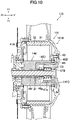
- FIG. 10 is a cross-sectional view showing a rear-wheel hub 141 as the modified example. A difference from the rear-wheel hub described hereinabove will hereinafter be described. To items not described with respect to the rear-wheel hub 141, there may be applied the structure of the rear wheel hub described hereinabove, or a structure of the rear wheel hub described hereinafter.
- a support 146 of a drive unit 110 may have a positioning member 146D in addition to the stator holding member 46A and the coupling member 46B.
- the positioning member 146D is a member formed separately from the stator holding member 46A.
- the positioning member 146D may be attached to the stator holding member 46A with the nut 46g.
- the stator holding member 46A may have a recessed part in the right portion thereof. Inside the recessed part, there is arranged the positioning member 146D in addition to the one-way clutch 23, the bearing 47B, and so on.
- the positioning member 146D may have a flange 46i at a right end thereof.
- the flange 46i may bias the bearing 49B, which supports the rear-wheel hub 41, leftward.
- the bearing 49B may be clamped by a step formed on the outer circumferential surface of the stator holding member 46A and the flange 46i to thereby be positioned in a direction along the rotational center line Ax1.
- the rear-wheel hub 141 of the drive unit 110 may have the left wall 41A, a right member 141B, and a lid member 141C.
- the lid member 141C is a member formed separately from the right member 141B.
- the right member 141B may have an opening at a position corresponding to the transmission shaft 21 and the positioning member 146D.
- the lid member 141C may be attached to an edge of the opening with a fixation tool such as a screw 83.
- the lid member 141C may have the holding cylindrical part 41c protruding leftward. Inside the holding cylindrical part 41c, there may be arranged the one-way clutch 23, the bearing 47B, and the right end of the transmission shaft 21.
- An outer ring of the bearing 49B at the right side may be press fitted to the right member 141B.
- the positioning member 146D may be attached to a recessed part of the stator holding member 46A from the right side in a state in which the lid member 141C is not attached to an opening of the right member 141B.
- the coupling member 46B, the stator holding member 46A, and the positioning member 146D may be fixed to each other with the bolt 46f and the nut 46g, and then, the opening of the right member 141B is blocked by the lid member 141C.
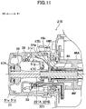
- FIG. 11 is a cross-sectional view showing the drive unit 210 as the present example. A difference between the drive unit 210 and the drive units described hereinabove will hereinafter be described. To items not described with respect to the drive unit 210, there may be applied the structure of the drive unit described hereinabove, or a structure of the drive unit described hereinafter.
- the transmission shaft 221 has a left shaft 221A and a right shaft 221B.
- a left end of the left shaft 221A may be supported by the case lid 51e of the rear case 51 via the bearing 47A similarly to the drive unit 10 shown in FIG. 3B and so on.
- a right end of the left shaft 221A may be supported by the bearing 47C fitted to an inner edge of an opening (an opening provided to the right portion 51g) of the partition wall 51c formed in the rear case 51.
- a left end of the right shaft 221B may be supported by the bolt 46f via a bearing 47D.
- the bolt 46f has a recessed part, which opens leftward, at the left end.
- the bearing 47D may be held inside the recessed part.
- the right shaft 221B may be fitted inside the bearing 47D, and the left end of the right shaft 221B may be supported by the bolt 46f via the bearing 47D.
- a right end of the right shaft 221B may be supported by the support 46 via the right member 41B of the rear-wheel hub 41 and the bearing 47B similarly to the drive unit 10 shown in, for example, FIG. 3B .
- the right end of the right shaft 221B may be supported by the support 46 via the lid member 141C and the bearing 47B similarly to the drive unit 110 shown in, for example, FIG. 10 .
- the left shaft 221A and the right shaft 221B are coupled to each other so that the power can be transmitted.
- the left shaft 221A and the right shaft 221B may be coupled to each other with the spline.
- the left shaft 221A and the right shaft 221B can be separated from each other in a direction along the rotational center line Ax1.
- the left shaft 221A is held by the rear arm 50
- the right shaft 221B is held by the rear-wheel hub 41.
- the right shaft 221B is coupled to the left shaft 221A. According to the above, the work of attaching the rear-wheel hub 41 to the rear arm 50 can be made easier.
- the torque sensor 64 for detecting the tread force acting on the pedals 63 is provided to the crank shaft 61.
- the position of the torque sensor 64 is not limited thereto.
- the torque sensor 64 is provided to the right shaft 221B. More particularly, the torque sensor 64 is attached to an inner circumferential surface of the through hole of the bolt 46f in which the right shaft 221B is inserted.
- An electric wire 64a coupled to the torque sensor 64 may be coupled to the motor control device 11 passing through the second housing chamber S2 of the rear case 51, and the shaft case 53 similarly to the electric wire structure including the electric wire parts 33, 34.
- an electric wire path 46k through which the electric wire 64a passes may be formed in the bolt 46f.
- the torque sensor 64 is, for example, a sensor (e.g., a magnetostrictive sensor) for outputting a signal corresponding to torsion of the right shaft 221B.
- FIG. 12 is a diagram showing a drive unit 310 having such a structure. The drawing is substantially the same in cutting plane as FIG. 3A .
- the drive shaft 27 has a detection target shaft in a part in the extending direction thereof.
- the drive shaft 27 has a detection target shaft 27a in a foremost portion thereof.
- a shaft main body 27b and the detection target shaft 27a of the drive shaft 27 may be engaged with each other using a spline.
- the torque sensor 64 may be arranged so as to surround the detection target shaft 27a.
- a sensor holder 56e having a cylindrical shape may be arranged inside the front case 56.
- the torque sensor 64 may be attached to an inner circumferential surface of the sensor holder 56e.
- the electric wire 64a extending from the torque sensor 64 may be coupled to the motor control device 11 housed in the circuit housing section 56C passing through the electric wire path 56f provided to the sensor holder 56e and the front case 56.
- the torque sensor 64 is, for example, a sensor (e.g., a magnetostrictive sensor) for outputting a signal corresponding to torsion of the detection target shaft 27a.
- the brake system 71 provided to the drive unit 10 is a disc brake system. Unlike the above, the brake system may be a drum brake system.
- FIG. 13A and FIG. 13B are diagrams showing a drive unit 410 having the drum brake system.
- FIG. 13A is a left side view
- FIG. 13B is a cross-sectional view in the Xlllb-Xlllb line shown in FIG. 13A .
- a difference between the drive unit 410 and the drive units described hereinabove will hereinafter be described. To items not described with respect to the drive unit 410, there may be applied the structure of the drive units described hereinabove.
- a brake system 471 (see FIG. 13B ) has two brake shoes 471c, and brake linings 471d respectively attached to outer circumferential surfaces of the brake shoes 471c (see FIG. 13B ). These may be supported by, for example, a pivot shaft 471e (see FIG. 13A ) attached to the rear case 51.
- the rear-wheel hub 41 may have a brake ring 471f attached thereon.
- the brake ring 471f may be fixed to, for example, an inside of an annular part 41f protruding leftward from a left side surface of the left wall 41A of the rear-wheel hub 41.
- the brake shoes 471c may be arranged inside the brake ring 471f.
- the brake system 471 may have a cam shaft 471a, and a cam shaft lever 471b for rotating the cam shaft 471a (see FIG. 13A ).
- the cam shaft 471a may be supported by, for example, the rear case 51, and may be arranged between end portions of the two brake shoes 471c.
- the first power system for transmitting the power of the electric motor 30 to the rear-wheel hub 41 may have the reduction mechanism.
- the drive unit 10 may have a plurality of shafts arranged along the rotational center line Ax1 of the rear wheel 40 as the transmission shaft. The locations of all or some of the shafts as the transmission shafts may be shifted from the rotational center line Ax1.
- the second power system for transmitting the power of the crank shaft 61 to the rear-wheel hub 41 may have the speed change mechanism.
- the support 46 has the stator support member 46A, the coupling member 46B, and the bolt 46f for fixing the stator support member 46A and the coupling member 46B to each other.
- the stator support member 46A and the coupling member 46B may integrally be molded. In this case, the support 46 is not required to have the bolt 46f.
Landscapes
- Engineering & Computer Science (AREA)
- Chemical & Material Sciences (AREA)
- Combustion & Propulsion (AREA)
- Mechanical Engineering (AREA)
- Transportation (AREA)
- Arrangement Or Mounting Of Propulsion Units For Vehicles (AREA)
Abstract
Description
- The invention relates to a drive unit and a bicycle having a drive unit.
-
JP 6633148 B - It is an object of the present invention to provide a drive unit in which an electric motor is arranged in the rear wheel, wherein detachment of the rear wheel from the rear arm can be achieved with a simple operation for, for example, an inspection of the electric motor. According to the present invention said object is solved by a drive unit having the features of independent claim 1. Preferred embodiments are laid down in the dependent claims.
- (1) An example of a drive unit proposed in the present disclosure includes a rear-wheel hub provided to a rear wheel, a first power system which includes an electric motor including a stator and a rotor, and housed in the rear-wheel hub, and is configured to transmit power of the electric motor to the rear-wheel hub, a rear arm arranged in a first direction as one of a right side and a left side with respect to the rear wheel, a second power system which includes a crank shaft with pedals, a transmission shaft arranged along a rotational center line of the rear-wheel hub, and a power transmission mechanism arranged along the rear arm, and engaged with the crank shaft and the transmission shaft to transmit the power from the crank shaft to the transmission shaft, and is configured to transmit the power to the rear-wheel hub through the transmission shaft, and an electric wire structure including a first electric wire part extending from the electric motor, a second electric wire part extending along the rear arm, and an electric wire coupling part electrically coupling the first electric wire part and the second electric wire part to each other. The rear-wheel hub is provided with a support supporting the rear-wheel hub so as to allow the rear-wheel hub to rotate. The rear arm has a first case houses an engaging part between the power transmission mechanism and the transmission shaft. The first case is attached to the support with at least one fixation tool. The electric wire structure extends from the first case toward an inside of the rear-wheel hub passing through an electric wire path provided to the support. The electric wire coupling part is located between an end surface of the first case in the first direction and an end surface of the rear-wheel hub in a second direction as an opposite direction to the first direction. According to this drive unit, the detachment work of the rear wheel from the rear arm can be made easy.
- (2) In the drive unit according to (1), the support may have a stator holding member that has the stator attached thereon, and a coupling member. At least a part of the coupling member may be located at an outer side of the rear-wheel hub in a direction along the rotational center line of the rear-wheel hub. The first case may be attached to the at least a part of the coupling member with the at least one fixation tool.
- (3) In the drive unit according to (2), the at least a part of the coupling member may be larger in diameter than the stator holding member. This structure allows the number of attachment positions between the coupling member and the first case to easily increase.
- (4) In the drive unit according to (1), the electric wire coupling part is arranged inside the first case. This structure enables effective use of the space in the first case, and prevents an increase in size in the horizontal direction of the rear-wheel hub and the first case.
- (5) In the drive unit according to (1), the first electric wire part may have a length that allows the first electric wire to passe through the electric wire path and reach an outside of the rear-wheel hub. This structure simplifies the coupling work of the first electric wire part and the second electric wire part.
- (6) In the drive unit according to (1), the second electric wire part may have a length that allows the second electric wire part to exceed an end surface closer to the support of the first case. This structure simplifies the coupling work of the first electric wire part and the second electric wire part.
- (7) In the drive unit according to (1), the electric wire coupling part may be a terminal block that has an end portion of the first electric wire part attached thereon. At least a part of the electric wire coupling part may protrude from a side surface of the support, the side surface being a surface located toward the first case. This structure simplifies the coupling work of the first electric wire part and the second electric wire part.
- (8) In the drive unit according to (1), the first case may have a first housing chamber which houses the engaging part between the power transmission mechanism and the transmission shaft, and a second housing chamber partitioned from the first housing chamber. The electric wire structure may pass through the second housing chamber. This structure enables protection of the electric wire structure. For example, it is possible to prevent the lubricant used in an engaging part between the power transmission mechanism and the transmission shaft from adhering to the electric wire structure. Further, it is possible to prevent the electric wire structure from making contact with the engaging part between the power transmission mechanism and the transmission shaft.
- (9) In the drive unit according to (8), at least a part of the second housing chamber may be located at an outer side in a radial direction of the transmission shaft with respect to the first housing chamber. This structure enables the space in the first case to be used more effectively.
- (10) In the drive unit according to (9), at least a part of the second housing chamber may surround the transmission shaft. This structure enables gentle bending of the electric wire structure passing through the second housing chamber, and thus, simplifies the coupling work of the first electric wire part and the second electric wire part.
- (11) In the drive unit according to (10), the rear arm may have a second case which is located at a front side of the first case, and houses the power transmission mechanism. The second case may include, within the second case, a first arm chamber which houses the power transmission mechanism, and a second arm chamber which houses the second electric wire part.
- (12) In the drive unit according to (1), the first case may support a first end portion of the transmission shaft via a first bearing, the support may support a second end portion of the transmission shaft via a second bearing. Further, one of the first end portion and the second end portion may be detached from the first case or the support which supports the one of the end portions when the first case and the rear-wheel hub is separated from each other. The first case or the support which supports the other of the first end portion and the second end portion may support the transmission shaft via a third bearing located between the first bearing and the second bearing. This structure allows the posture of the transmission shaft with respect to the first case (or the support) maintained, when the first case and the rear-wheel hub from each other being separated.
- (13) In the drive unit according to (1), the at least one fixation tool may be arranged outside the first case. This structure simplifies the work of detaching the rear-wheel hub from the rear arm and the work of attaching the rear-wheel hub to the rear arm.
- (14) The drive unit according to (13) may include a plurality of fixation tools each of which is the at least one fixation tool. A plurality of fixation tools arranged in a circumferential direction surrounding the transmission shaft.
- (15) An example of the bicycle proposed in the present disclosure includes the drive unit described in (1).
-
-
FIG. 1 is a left side view showing an example of a bicycle proposed in the present disclosure. -
FIG. 2A is a left side view of a drive unit provided to the bicycle shown inFIG. 1 . -
FIG. 2B is a plan view of the drive unit shown inFIG. 2A . -
FIG. 2C is a right side view of the drive unit shown inFIG. 2A . -
FIG. 3A is a cross-sectional view in IIIa-IIIa shown inFIG. 2A . -
FIG. 3B is an enlarged view of a rear portion of the drive unit shown inFIG. 3A . -
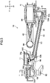
FIG. 4 is a cross-sectional view in IV-IV shown inFIG. 2A . -
FIG. 5 is a cross-sectional view in V-V shown inFIG. 2A . -
FIG. 6A is a cross-sectional view in VIa-VIa shown inFIG. 2B . -
FIG. 6B is a cross-sectional view in Vlb-Vlb shown inFIG. 6A . -
FIG. 7A is a cross-sectional view showing a modified example of a shaft case shown inFIG. 6A , and is substantially the same in cutting plane asFIG. 6A . -
FIG. 7B is a cross-sectional view in Vllb-Vllb shown inFIG. 7A . -
FIG. 8A is a left side view of a rear wheel with a rear arm detached. -
FIG. 8B is a perspective view of a rear-wheel hub, a coupling member, and a terminal block shown inFIG. 8A . -
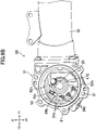
FIG. 9A is a cross-sectional view of a rear portion of the rear arm with the rear-wheel hub detached, and is the same in cutting plane asFIG. 3B . -
FIG. 9B is a perspective view of the rear portion of the rear arm shown inFIG. 9A . -
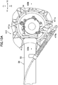
FIG. 10 is a cross-sectional view showing a modified example of the rear-wheel hub and a support.FIG. 10 is the same in cutting plane asFIG. 3B . -
FIG. 11 is a cross-sectional view showing a modified example of an arrangement of a transmission shaft and a torque sensor, and is the same in cutting plane asFIG. 3B . -
FIG. 12 is a cross-sectional view showing a modified example of an arrangement of the torque sensor, and is the same in cutting plane asFIG. 3A . -
FIG. 13A is a left side view showing a modified example of the drive unit in which a drum brake system is adopted as a brake system. -
FIG. 13B is a cross-sectional view represented by a line Xlllb-Xlllb shown inFIG. 13A . - In the present specification, as an example, a bicycle 1 and a
drive unit 10 shown inFIG. 1 and so on will be described. InFIG. 1 , directions indicated by Y1 and Y2 are referred to as a front side and a rear side, respectively, and directions indicated by Z1 and Z2 are referred to as an upper side and a lower side, respectively. Directions indicated by X1 and X2 shown inFIG. 2B are referred to as a right side and a left side, respectively. Further, a direction of X1-X2 is referred to as a horizontal direction, or a "direction along a rotational center line Ax1." - It should be noted that in the specification, there is described an example in which a
rear arm 50 described later is arranged at the left side of arear wheel 40. However, it is possible for therear arm 50 to be arranged at the right side of therear wheel 40. In a structure in which therear arm 50 is arranged at the right side of therear wheel 40, a structure described hereinafter may be opposite with respect to relative positions of components and members in the horizontal direction. - As shown in
FIG. 1 , the bicycle 1 has afront fork 3, afront wheel 2 supported by a lower end of thefront fork 3, and asteering bar 4 coupled to thefront fork 3 via a steering shaft. The bicycle 1 has a saddle 6. The saddle 6 is supported by an upper end of asaddle post 7a. - It is possible to arrange a crank 60 at the lower side of the
saddle post 7a. Thecrank 60 has a crank shaft 61 (seeFIG. 3A ), crank arms 62 (seeFIG. 2A ) attached to both end portions of thecrank shaft 61, and pedals 63 (seeFIG. 2A ) respectively attached to the crankarms 62. - As shown in
FIG. 1 , abody frame 7 may include ahead pipe 7b which supports thesaddle post 7a and the steering shaft, and adown frame 7c extending obliquely downward from thehead pipe 7b. It is possible to fix abracket 7d to a lower end of thesaddle post 7a and a lower end of thedown frame 7c. Thedrive unit 10 of the bicycle 1 may include a front case 56 (seeFIG. 2A ) which is located at the forefront of therear arm 50 described later to hold thecrank 60. Thefront case 56 may be attached to thebracket 7d. The bicycle 1 has a battery 13 (seeFIG. 1 ) for storing electric power to be supplied to anelectric motor 30 described later. Thebattery 13 may be attached to, for example, thedown frame 7c. The structure of thebody frame 7, the support structure of thefront case 56, an arrangement of thebattery 13, and so on are not limited to the example described here. - An accelerator grip may be disposed in a right portion of the
steering bar 4. The accelerator grip may include an accelerator sensor for detecting an operation amount (a rotational position) of the accelerator grip. The bicycle 1 has arear wheel 40 and the electric motor 30 (seeFIG. 3A ) provided to therear wheel 40. An output signal of the accelerator sensor may be input to a motor control device 11 (seeFIG. 3A ). Themotor control device 11 may generate a command value corresponding to the operation amount of the accelerator grip. Further, themotor control device 11 may supply the electric power corresponding to the command value to theelectric motor 30. Themotor control device 11 includes an inverter to convert a direct current obtained from thebattery 13 into, for example, an alternating current with a frequency corresponding to the command value, and then supply the alternating current to theelectric motor 30. On this occasion, the bicycle 1 may be driven only with the power obtained from theelectric motor 30. - The power (rotational force) of the
crank 60 is transmitted to therear wheel 40 via a power transmission mechanism described later. Thecrank shaft 61 may include a torque sensor 64 (seeFIG. 3A ) for detecting a force (a tread force) applied to the pedal 63 by the user. Thetorque sensor 64 may include a transmission member arranged in an inner circumferential portion of thetorque sensor 64, and a detection section including a detecting coil and a magnetic circuit. A part (e.g., a left portion) of the transmission member may be serration-fitted to an outer circumference of thecrank shaft 61, and another part (e.g., a right portion) of the transmission member may be serration-fitted to agear 65. The transmission member may rotate integrally with thecrank shaft 61, and the rotation of thecrank shaft 61 may be transmitted to thegear 65 via the transmission member. The detecting coil of thetorque sensor 64 may output a signal corresponding to, for example, a twist of the transmission member. Thetorque sensor 64 may be, for example, a magnetostrictive sensor. An output signal of thetorque sensor 64 may be input to themotor control device 11. Themotor control device 11 generates a command value corresponding to the tread force. Themotor control device 11 supplies theelectric motor 30 with the electric power corresponding to the command value, and theelectric motor 30 is driven by the electric power. Due to this drive of theelectric motor 30, pedaling with thepedals 63 by the user is aided. Further, in the state in which theelectric motor 30 is not driven, it is possible to drive therear wheel 40 only with the power transmitted from thecrank shaft 61 via the power transmission mechanism. - In other words, it is possible for the bicycle 1 to make the drive in the following three modes possible:
- (i) a drive only with the power of the electric motor 30 (a motor-driven mode);
- (ii) a drive with the power of the
electric motor 30 and the tread force applied to the pedals 63 (an assist mode); and - (iii) a drive only with the tread force applied to the pedals 63 (a human power mode). The bicycle 1 may include a switch for the user to switch between such three modes.
- It should be noted that the structure proposed in the present disclosure can be applied not only to the bicycle in which the three modes can be selected as described above, but also to, for example, a bicycle in which only (ii) the assist mode and (iii) the human power mode may be selected. In this case, the bicycle is not required to have the accelerator grip and the accelerator sensor.
- The structure of the
drive unit 10 will hereinafter be described. Thedrive unit 10 has two power systems. As illustrated inFIG. 3A , a first power system includes theelectric motor 30, and transmits the rotation of arotor 32 provided to theelectric motor 30 to ahub 41 of therear wheel 40. A second power system includes thecrank shaft 61 with thepedals 63, and transmits the rotation (power) of thecrank shaft 61 to thehub 41 of the rear wheel 40 (thehub 41 is hereinafter referred to as a rear-wheel hub). - As shown in
FIG. 3B , theelectric motor 30 has astator 31 and therotor 32. Thestator 31 has a plurality of iron cores arranged circularly centering on the rotational center line Ax1 of therear wheel 40, and coils respectively wound around the iron cores. Therotor 32 has a plurality of magnets arranged circularly centering on the rotational center line Ax1 of therear wheel 40. In thedrive unit 10, it is possible for therotor 32 to be located outside in a radial direction with respect to thestator 31, and to be opposed to thestator 31 in the redial direction. In other words, theelectric motor 30 may be a radial-gap type electric motor. Unlike thedrive unit 10, it is possible for theelectric motor 30 to be an axial-gap type electric motor. In other words, therotor 32 and thestator 31 may be opposed to each other in the axial direction (a direction of the rotational center line Ax1). Theelectric motor 30 may be a transverse magnetic flux type motor which forms a magnetic path perpendicular to the rotational direction. In the motor of this kind, the stator may include an armature core and a coil, and the rotor may include a field core and a magnet. A magnetic flux perpendicular to the rotational direction may be formed in at least one of the armature core and the field core. - As shown in
FIG. 3A , therear wheel 40 has arim 43 that has atire 44 attached thereon, and the rear-wheel hub 41. Further, therear wheel 40 hasspokes 45 which extend in the radial direction from thehub 41 to support therim 43. Therotor 32 may be fixed to an inner surface of the rear-wheel hub 41. Further, therotor 32 and the rear-wheel hub 41 may rotate integrally with each other. In the structure in which no reduction gear intervenes between the rear-wheel hub 41 and theelectric motor 30 as described above, there is no loss due to the reduction gear, and thus, it is possible to efficiently drive therear wheel 40. - As shown in
FIG. 3A , on thecrank shaft 61, there may be arranged the gear 65 (a bevel gear in the example of the bicycle 1) which rotates integrally with thecrank shaft 61, and thetorque sensor 64 described above. A power transmission path (the second power system) for transmitting the power (rotation) of thecrank shaft 61 to the rear-wheel hub 41 may be provided to atransmission shaft 21. Thetransmission shaft 21 is separated rearward from thecrank shaft 61, and may be located on the rotational center line Ax1 of therear wheel 40. As described later in detail, therear arm 50 may include arear case 51 in a rear portion of therear arm 50. It is possible for thetransmission shaft 21 to be supported by therear case 51 so as to be able to rotate. - The second power system may include a power transmission mechanism for transmitting the power (rotation) of the
crank shaft 61 to thetransmission shaft 21. The power transmission mechanism may be a shaft drive mechanism. In other words, as shown inFIG. 3A , the power transmission mechanism may include the gear 65 (specifically the bevel gear) disposed on thecrank shaft 61, a gear 26 (specifically a bevel gear) provided to thetransmission shaft 21, and adrive shaft 27 arranged along a front-back direction of a vehicle body in a side view of the vehicle body. Thedrive shaft 27 may have agear 27A (specifically a bevel gear) engaged with thegear 65 on thecrank shaft 61 at the front end of thedrive shaft 27. Further, thedrive shaft 27 may have agear 27B (specifically a bevel gear) engaged with thegear 26 on thetransmission shaft 21 at the rear end of thedrive shaft 27. - = Unlike the example described here, the
drive unit 10 may have a chain drive mechanism, a belt drive mechanism, or the like as the power transmission mechanism. In other words, thedrive unit 10 may have a chain or a belt instead of thedrive shaft 27. - A one-way clutch may be arranged in the power transmission path between the
crank shaft 61 and the rear-wheel hub 41. In thedrive unit 10, as shown inFIG. 3A , a one-way clutch 23 may be arranged between thetransmission shaft 21 and the rear-wheel hub 41. The one-way clutch 23 transmits the rotational force of thetransmission shaft 21 to the rear-wheel hub 41 on the one hand, but does not transmit the rotational force of the rear-wheel hub 41 to thetransmission shaft 21 on the other hand. - The
rear arm 50 is arranged in only one of the right side and the left side with respect to therear wheel hub 41, but is not arranged in the other thereof. As shown inFIG. 3A , in thedrive unit 10, therear arm 50 is arranged at the left side of the rear-wheel hub 41, but is not arranged at the right side thereof. Therefore, a worker of the maintenance can easily perform detachment of the rear-wheel hub 41 from therear arm 50 toward the right side. Contrary to the example shown inFIG. 3A , it is possible for therear arm 50 to be arranged only at the right side of the rear-wheel hub 41. - The power transmission mechanism for transmitting the rotation of the
crank shaft 61 to thetransmission shaft 21 may be arranged at the left side of therear wheel 40 together with therear arm 50. As shown inFIG. 3A , in thedrive unit 10, thedrive shaft 27 is arranged at the left side of therear wheel 40. Thedrive shaft 27 may be coupled to the left portion of thetransmission shaft 21. Thetransmission shaft 21 may extend rightward from the rear portion of therear arm 50 to be arranged inside thestator 31 in the radial direction. Further, thetransmission shaft 21 may be coupled to the rear-wheel hub 41 at an opposite side to (i.e., the right side of) thedrive shaft 27 and therear arm 50 across the center C1 of therear wheel 40 in the horizontal direction. Due to this structure, it is possible to realize both of the support of the rear-wheel hub 41 by therear arm 50 arranged only at the left side, and the power transmission from thecrank shaft 61 to the rear-wheel hub 41. - As shown in
FIG. 3A , thedrive unit 10 may have thefront case 56 which holds thecrank 60 in the front portion of thedrive unit 10. Therear arm 50 may have ashaft case 53 which has a cylindrical shape and extends rearward from thefront case 56, and therear case 51 located in the rear portion of therear arm 50. Thedrive shaft 27 may be housed in theshaft case 53, and may be held by a bearing disposed inside theshaft case 53 so as to be rotatable. As described above, the bicycle 1 may have a chain drive mechanism or a belt drive mechanism as the power transmission mechanism. In this case, therear arm 50 may have a case for housing the chain or a case for housing the belt instead of theshaft case 53. To therear case 51, there may be attached a support 46 (seeFIG. 3B ) which supports the rear-wheel hub 41. - As shown in
FIG. 3A , in thefront case 56, there may be housed thegear 65 and thetorque sensor 64 arranged on thecrank shaft 61. Both end portions of thecrank shaft 61 protrude in the axial direction from thefront case 56. The crankarms 62 are respectively coupled to the both end portions of thecrank shaft 61. Thefront case 56 may be attached to thebracket 7d (seeFIG. 1 ) disposed in the lowermost portion of thebody frame 7. Thebracket 7d may be, for example, shaped like a box opening downward. Thefront case 56 may be arranged inside thebracket 7d, and attached to thebracket 7d. - The
rear case 51 may be connected to a rear end of the shaft case 53 (seeFIG. 3A ). Therear case 51 may have a connection opening which opens toward the front side. The rear end of theshaft case 53 may be fitted to the connection opening of therear case 51, and may be connected to therear case 51 with a fixation tool such as a screw. Therear case 51 may house thegears rear case 51 and theshaft case 53 is not limited to the example of the bicycle 1, and may arbitrarily be modified. - As shown in
FIG. 3A , the position of therear case 51 is distant leftward from the center C1 (the center in the horizontal direction of the vehicle body) in the horizontal direction of therear wheel 40. Theshaft case 53 may extend obliquely frontward from therear case 51 toward the center C1. The front end of theshaft case 53 may be located at the front side of therear wheel 40 and theelectric motor 30. In other words, the front end of theshaft case 53 may overlap therear wheel 40 and theelectric motor 30 in a front view of the vehicle. - As shown in
FIG. 3B , the rear-wheel hub 41 may have aright member 41B and aleft wall 41A. Theright member 41B may have aright wall 41d which covers a right side surface of theelectric motor 30, and acylindrical part 41e which extends leftward from theright wall 41d to cover an outer circumference of thestator 31. To an inner surface of thecylindrical part 41e, there may be fixed therotor 32. Therear arm 50 is arranged only at the left side of therear wheel 40. Therefore, theright member 41B of the rear-wheel hub 41 is not required to be provided with an opening through which thetransmission shaft 21 and thesupport 46 described later pass. Theright member 41B opens leftward. Theleft wall 41A may cover a left side surface of theelectric motor 30, and may be fixed to an outer circumferential edge of thecylindrical part 41e. Theleft wall 41A may be fixed to thecylindrical part 41e with a plurality of fixation tools (screws 42 or bolts) arranged in a circumferential direction. - The structure of the rear-
wheel hub 41 is not limited to the example of the bicycle 1. For example, the rear-wheel hub 41 may be constituted by three members. For example, theleft wall 41A, theright wall 41d, and thecylindrical part 41e may individually be formed, and may be fixed to each other with a fixation tool such as a bolt or a screw. - As shown in
FIG. 3B , thetransmission shaft 21 may be coupled to theright member 41B via the one-way clutch 23. On an inner surface of theright wall 41d of theright member 41B, there may be formed a holdingcylindrical part 41c. The holdingcylindrical part 41c may protrude leftward. The holdingcylindrical part 41c may be located inside an end portion of thesupport 46 described later. The rightmost portion of thetransmission shaft 21 may be located inside the holdingcylindrical part 41c. Further, between the inner circumferential surface of the holdingcylindrical part 41c and the outer circumferential surface of thetransmission shaft 21, there may be arranged the one-way clutch 23. As described above, the position of the one-way clutch 23 is downstream of thedrive shaft 27 in the power transmission path from thecrank shaft 61 up to the rear-wheel hub 41. Therefore, when, for example, the bicycle runs only with the power of theelectric motor 30, no rotation of thedrive shaft 27 occurs. As a result, it is possible to prevent the power of theelectric motor 30 from being wasted by the rotation of thedrive shaft 27. - The
drive unit 10 has abrake system 71 for therear wheel 40. Thebrake system 71 is, for example, a disc brake system, and has abrake disc 72 rotating integrally with the rear-wheel hub 41, and acaliper 73 as shown inFIG. 2A . As shown inFIG. 3B , thebrake disc 72 may be attached to, for example, theleft wall 41A. Thecaliper 73 may be supported by therear arm 50. Specifically, therear arm 50 may have a caliper holding member 74 (seeFIG. 2A ) attached thereon. Thecaliper holding member 74 may be supported by theshaft case 53 via, for example, abracket 53a (seeFIG. 2A ). A structure of thebrake system 71 is not limited to the example of thedrive unit 10. For example, thebrake system 71 may be a drum brake system (seeFIG. 13A andFIG. 13B ). - As shown in
FIG. 3B , thedrive unit 10 may have thesupport 46 for supporting the rear-wheel hub 41 so as to allow the rear-wheel hub 41 to rotate. At the center of thesupport 46, there may be formed a through hole penetrating thesupport 46 along the rotational center line Ax1 of therear wheel 40, and thetransmission shaft 21 may be arranged in the through hole.Bearings support 46, and thesupport 46 may support the rear-wheel hub 41 through thebearings bearing 49A at the left side may be arranged between an inner edge of theleft wall 41A of the rear-wheel hub 41 and thesupport 46. The bearing 49B at the right side may be arranged between theright wall 41d of the rear-wheel hub 41 and an outer circumferential surface of an end portion of thesupport 46. - As shown in
FIG. 3B , thesupport 46 may have astator holding member 46A arranged inside thestator 31. Thestator 31 may be fixed to an outer circumferential surface of thestator holding member 46A. For example, the iron cores constituting thestator 31 may be press-fitted or bonded to the outer circumferential surface of thestator holding member 46A. - As shown in
FIG. 3B , thesupport 46 may further have acoupling member 46B. Thecoupling member 46B may have awall part 46a located at an outer side of the rear-wheel hub 41 in a direction along the rotational center line Ax1 of the rear-wheel hub 41. In thedrive unit 10, thewall part 46a may be located at the left side of theleft wall 41A of the rear-wheel hub 41. Therear case 51 of therear arm 50 may be attached to the outer circumferential portion of thewall part 46a (seeFIG. 4 ) with a plurality of fixation tools. At the outer side of therear case 51, there may be formed a plurality of attachment holes arranged side by side along the outer circumference of therear case 51. As shown inFIG. 2A andFIG. 4 , therear case 51 may be fixed to the outer circumferential portion of thewall part 46a of thesupport 46 with a plurality ofscrews 81 respectively fitted to the attachment holes. By detaching thescrews 81, it is possible to detach therear wheel 40 from therear arm 50. Thus, the maintenance work of, for example, theelectric motor 30 can be made easy. - As shown in
FIG. 4 , thescrews 81 may be inserted into the attachment holes provided to therear case 51 and screw holes provided to the outer circumferential portion of thewall part 46a of thesupport 46 from the left side thereof (at the side where therear arm 50 is arranged). As shown inFIG. 2A , thescrews 81 may be exposed in the left side view of the vehicle body. Therefore, the detachment work of thescrews 81 becomes easy. - The
wall part 46a may have a disc-like shape (seeFIG. 8B ). Thewall part 46a may be larger in outside diameter than thestator holding member 46A as shown inFIG. 4 . The outside diameter of thewall part 46a may correspond to the outside diameter of therear case 51. Thus, it is possible to simplify the fixation structure of thewall part 46a and therear case 51. The outer circumferential edge (a portion where the screw holes are formed) of thewall part 46a may be larger in outside diameter than thebearing 49A which supports the rear-wheel hub 41. - The
coupling member 46B and thestator holding member 46A may be components formed individually. These may be fixed to each other with a fixation tool such as a screw or a bolt. In thedrive unit 10, as shown inFIG. 4 , thecoupling member 46B and thestator holding member 46A may include a hole penetrating thecoupling member 46B and thestator holding member 46A along the rotational center line Ax1 of therear wheel 40. Abolt 46f may be fitted to this hole. Thecoupling member 46B and thestator holding member 46A may be fixed to each other with thebolt 46f and anut 46g (seeFIG. 3B ). Thebolt 46f may be fitted to the through hole provided to thecoupling member 46B and thestator holding member 46A from, for example, the left side of thecoupling member 46B. Thenut 46g may be fixed to thebolt 46f at the right side of thestator holding member 46A. - The
bolt 46f and thenut 46g for fixing thecoupling member 46B and thestator holding member 46A to each other may include the hole penetrating these in the direction along the rotational center line Ax1. In other words, thebolt 46f may have a cylindrical shape. Thetransmission shaft 21 may be arranged inside the through hole. Thetransmission shaft 21 is made rotatable inside the through hole. According to this fixation structure, it is possible to reduce the number of components necessary to fix thecoupling member 46B and thestator holding member 46A to each other, and thus it is possible to simplify the assembling work of these members. - Between the inner circumferential surface of the support 46 (the
bolt 46f) and the outer circumferential surface of thetransmission shaft 21, there may be ensured a clearance. Thus, there is no friction between thetransmission shaft 21 and thesupport 46, and it is possible for thetransmission shaft 21 to smoothly rotate. - As shown in
FIG. 4 , thetransmission shaft 21 may have acoupling part 21b located at the left side of thesupport 46. Thecoupling part 21b is housed in therear case 51, and is not required to be exposed to the outside. Due to this structure, it is possible to prevent external moisture and dust from entering the inside of the rear-wheel hub 41 through the clearance between the inner circumferential surface of thesupport 46 and the outer circumferential surface of thetransmission shaft 21. - It should be noted that the fixation structure of the
stator holding member 46A and thecoupling member 46B is not limited to the example of thedrive unit 10. For example, thebolt 46f may be inserted into the through hole provided to thestator holding member 46A and thecoupling member 46B from the right side of thestator holding member 46A. Further, in another example, it is possible to provide a plurality of attachment holes arranged side by side in a circumferential direction surrounding thetransmission shaft 21 to each of thestator holding member 46A and thecoupling member 46B. Further, thestator holding member 46A and thecoupling member 46B may be fixed to each other with bolts or screws to be inserted into the attachment holes. - As shown in
FIG. 3B , thestator holding member 46A may include a recessedpart 46h opening rightward. Thenut 46g may be arranged inside the recessedpart 46h. More specifically, the whole of thenut 46g may be arranged inside the recessedpart 46h. Thus, it is possible to suppress the increase in size of the rear-wheel hub 41 in the direction along the rotational center line Ax1. - In the
drive unit 10, as shown inFIG. 3B , a mechanism for coupling thetransmission shaft 21 and the rear-wheel hub 41 to each other may be housed inside the recessedpart 46h. Specifically, the one-way clutch 23, and abearing 47B which supports the right end of thetransmission shaft 21 may be housed inside the recessedpart 46h. Thus, it is possible to suppress the increase in size of the rear-wheel hub 41 in the direction along the rotational center line Ax1. - The
coupling member 46B may have acentral portion 46j (seeFIG. 4 ) arranged inside an inner edge of theleft wall 41A of the rear-wheel hub 41. Acollar 82 may be fitted at the outer side of thecentral portion 46j. Thebearing 49A at the left side supporting the rear-wheel hub 41 may be arranged between thecollar 82 and the inner edge of theleft wall 41A. Further, between thecollar 82 and the inner edge of theleft wall 41A, there may be arranged a seal member 49C. The seal member 49C is press-fitted in the inner edge of theleft wall 41A, and is thus fixed to the inner edge. An inner circumferential portion of the seal member 49C and an outer circumferential surface of thecollar 82 slide on each other. Thecollar 82 makes the smooth sliding motion possible. - As described above, the
drive unit 10 has amotor control device 11. Themotor control device 11 may be housed in acircuit housing section 56C fixed to a front portion of the rear arm 50 (seeFIG. 5 ). Themotor control device 11 and theelectric motor 30 are electrically coupled to each other with a plurality of electric wires. Specifically, themotor control device 11 and theelectric motor 30 may be coupled to each other with a plurality of power supply wires (e.g., three power supply wires) for supplying a drive current from themotor control device 11 to theelectric motor 30, and a plurality of signal wires for transmitting signals corresponding to a phase and a rotational speed of theelectric motor 30. In the specification, the plurality of power supply wires, and the plurality of signal wires described above, andconnectors terminal block 35 described later are referred to as an electric wire structure. - As shown in
FIG. 4 , the electric wire structure may have a firstelectric wire part 33 extending from theelectric motor 30. The firstelectric wire part 33 may include apower supply wire 33a and asignal wire 33b described above. Further, as shown inFIG. 5 , the electric wire structure may have a secondelectric wire part 34 arranged along therear arm 50. The secondelectric wire part 34 may also have apower supply wire 34a and asignal wire 34b (seeFIG. 6B andFIG. 7B ). - Further, the electric wire structure has an electric wire coupling part for coupling the first
electric wire part 33 and the secondelectric wire part 34 to each other. The electric wire coupling part may have, for example, the terminal block 35 (seeFIG. 4 andFIG. 8B ) for coupling thepower supply wires connectors FIG. 8B andFIG. 9A ) disposed in end portions of, for example, thesignal wires connectors - As shown in
FIG. 4 , thesupport 46 may have anelectric wire path 46m formed therein. Theelectric wire path 46m may be a hole or a groove which extends along the rotational center line Ax1 of therear wheel 40, and penetrates thesupport 46. Theelectric wire path 46m is located inside the seal member 49C and thebearing 49A. - Specifically, a
central portion 46j of thecoupling member 46B may have theelectric wire path 46m formed therein. An outer circumferential surface of thestator holding member 46A may partially be exposed on the inside of the rear-wheel hub 41. Anopening 46p at one end of theelectric wire path 46m may be formed on the portion thus exposed. Theelectric wire path 46m may communicate the inside of the rear-wheel hub 41 and the inside of therear case 51 with each other. Due to the above, it is possible to prevent the external moisture and dust from passing through theelectric wire path 46m to enter the inside of the rear-wheel hub 41. - The electric wire structure including the
electric wire parts rear case 51 toward the inside of the rear-wheel hub 41 through theelectric wire path 46m. The electric wire coupling part for coupling the firstelectric wire part 33 and the secondelectric wire part 34 to each other, namely theterminal block 35 and theconnectors rear case 51, and an end surface (a right side surface) of the rear-wheel hub 41. In other words, the electric wire coupling part may be located inside therear case 51, in theelectric wire path 46m, or inside the rear-wheel hub 41. More specifically, the electric wire coupling part may be located inside therear case 51, in theelectric wire path 46m, or inside the rear-wheel hub 41, and may be located at the left side of thestator 31. According to this structure, when detaching therear wheel 40 from therear arm 50, it becomes possible to easily perform coupling cancellation between the firstelectric wire part 33 and the secondelectric wire part 34, and thus, the detachment work can be made easier. - As shown in
FIG. 4 , a part of theterminal block 35 may be located inside therear case 51. For example, a portion (specifically, thescrew 35a (seeFIG. 8B )) for coupling theterminals FIG. 4 andFIG. 9 ) of thepower supply wires rear case 51. In other words, a portion (a third portion 35j described later) provided with thescrew 35a in theterminal block 35 may be located at the left side of an edge (aright end surface 51b; seeFIG. 9A ) at the rear-wheel hub 41 side of therear case 51. According to this structure, it is possible to effectively use a space in therear case 51 for the arrangement of the terminal block 35 (the electric wire coupling part). Further, since the coupling structure is not located in theelectric wire path 46m and the rear-wheel hub 41, it is possible to make the cross-sectional area of theelectric wire path 46m small, and further, it is possible to use the space in the rear-wheel hub 41 for the arrangement of theelectric motor 30. - The
power supply wire 33a and the terminal 33d may be molded with resin to form theterminal block 35. In other words, theterminal block 35 and thepower supply wire 33a can be molded by insert molding. In the insert molding, in a state in which thepower supply wire 33 that has the terminal 33d attached thereon is disposed in a die, melted resin as a material of theterminal block 35 is supplied to the inside of the die. Thus, theterminal block 35 having thepower supply wire 33a and the terminal 33d is formed. - The
power supply wire 33a may have a terminal in an end portion at an opposite side to the terminal 33d. To this terminal, there may be coupled a coil wire of thestator 31. This terminal may also be molded with resin together with thepower supply wire 33a. - The
terminal block 35 may be attached to, for example, thestator 31. As shown inFIG. 4 , theterminal block 35 may be attached to the left side surface of thestator 31. Theterminal block 35 may have afirst portion 35h arranged along the left side surface of thestator 31, asecond portion 35i extending in the axial direction, and the third portion 35j located in a left end portion. Thesecond portion 35i protrudes leftward beyond theelectric wire path 46m. The third portion 35j located in the left end portion of thesecond portion 35i may be provided with the terminal 33d of thepower supply wire 33a, and thescrew 35a for fixing the terminal 34d of thepower supply wire 34a to the terminal 33d. - Unlike the
power supply wire 33a, thesignal wire 33b may be an electric wire having a core wire formed of a conducting body, and a coat formed of resin. Thesignal wire 33b may be arranged along theterminal block 35, and may extend leftward passing through theelectric wire path 46m. Thesignal wire 33b may be attached to theterminal block 35. - The whole or a part of the
connector 34c disposed in an end portion of thesignal wire 34b and theconnector 33c disposed in an end portion of thesignal wire 33b may be located inside therear case 51. More specifically, at least a part of theconnectors right end surface 51b; seeFIG. 9A ) at the rear-wheel hub 41 side of therear case 51. - According to such an arrangement of the coupling structure of the
signal wires rear case 51. Further, since it is possible to reduce in size or eliminate the coupling structure located in theelectric wire path 46m and the rear-wheel hub 41, it is possible to make the cross-sectional area of theelectric wire path 46m small, and further, it is possible to use the space in the rear-wheel hub 41 for the arrangement of theelectric motor 30. - As shown in
FIG. 8B , a reinforcingmember 35B may be attached to thecoupling member 46B of thesupport 46. The reinforcingmember 35B may be fitted to theterminal block 35 to hold theterminal block 35. The reinforcingmember 35B may be attached to, for example, a left side surface of thecoupling member 46B to hold thesecond portion 35i and the third portion 35j of theterminal block 35. According to the above, it is possible to ensure the strength of theterminal block 35 by the reinforcingmember 35B while thinning a portion (thesecond portion 35i) located inside theelectric wire path 46m in theterminal block 35. The reinforcingmember 35B may have awall part 35d located between the twoterminals 33d adjacent to each other. - As shown in
FIG. 8B , the firstelectric wire part 33 may have a length with which the firstelectric wire part 33 passes through theelectric wire path 46m, and the end portion of the firstelectric wire part 33 reaches the outside (the left side) of the rear-wheel hub 41. For example, in the state in which the rear-wheel hub 41 is detached from therear arm 50, the end portion of the firstelectric wire part 33 may be located outside the rear-wheel hub 41. According to this structure, the coupling work of the firstelectric wire part 33 and the secondelectric wire part 34 can be made easy. - As shown in
FIG. 8B , the third portion 35j (the portion in which the terminal 33d of thepower supply wire 33a is disposed, and to which thescrew 35a is attached) of theterminal block 35 may protrude leftward more than the side surface (a left surface of thewall part 46a) at therear case 51 side of thecoupling member 46B. More desirably, the third portion 35j may protrude leftward more than an end surface (aleft end surface 46n) at therear case 51 side of thecoupling member 46B. - Further, when the
signal wire 33b is pulled outward (leftward) in the state in which the rear-wheel hub 41 is detached from therear arm 50, it is possible for theconnector 33c to be located at the left side of a side surface (a left surface of thewall part 46a) at therear case 51 side. More desirably, theconnector 33c may be located at the left side of theleft end surface 46n at therear case 51 side. Thus, the coupling work of the first electric wire part 33 (thepower supply wire 33a and thesignal wire 33b) and the second electric wire part 34 (thepower supply wire 34a and thesignal wire 34b) can be made easy. - It should be noted that the
terminal block 35 of thedrive unit 10 may be fixed to thecoupling member 46B of thesupport 46 instead of thestator 31. In this case, thepower supply wire 33a of the firstelectric wire part 33 may be an electric wire having a coat made of resin instead of the electric wire molded in theterminal block 35. In this case, thepower supply wire 33a may be extracted from the rear-wheel hub 41, and the terminal 33d attached to the end portion of thepower supply wire 33a may be coupled to theterminal block 35 with a screw. Further, the terminal 34d of thepower supply wire 34a may also be coupled to theterminal block 35 with a screw. Further, thepower supply wire 33a and thepower supply wire 34a may electrically be coupled to each other through a conducting body arranged in theterminal block 35. In this case, by detaching only thepower supply wire 34a from theterminal block 35, it is possible to detach the rear-wheel hub 41 from therear arm 50. The position of theterminal block 35 at which thepower supply wire 34a (the terminal 34d) is coupled may protrude leftward more than the end surface (theleft end surface 46n) at therear case 51 side of thecoupling member 46B. - As still another example, the
drive unit 10 is not required to have theterminal block 35. In this case, when thepower supply wire 33a is pulled outward (leftward) in the state in which the rear-wheel hub 41 is detached from therear arm 50, it is possible for the connector disposed in the end portion of thepower supply wire 33a to be located at the left side of the side surface (the left surface of thewall part 46a; seeFIG. 8B ) at therear case 51 side of thecoupling member 46B. More desirably, the connector disposed in the end portion of thepower supply wire 33a may be located at the left side of theend surface 46n at therear case 51 side of thecoupling member 46B. - As shown in
FIG. 9A , the secondelectric wire part 34 may also have a length exceeding an end surface (a right end surface) 51b at thesupport 46 side of therear case 51. For example, when the operator pulls the secondelectric wire part 34 outward (rightward) in the state in which the rear-wheel hub 41 is detached from therear arm 50, the end portion of the secondelectric wire part 34 may be located outside therear case 51. According to this structure, the coupling work of the firstelectric wire part 33 and the secondelectric wire part 34 may be made easy. - In the
drive unit 10, as shown inFIG. 9A , when thepower supply wire 34a is pulled outward (rightward) in the state in which the rear-wheel hub 41 is detached from therear arm 50, theseterminals 34d may be located at the right side of theright end surface 51b of therear case 51. Similarly, when thesignal wire 34b is pulled outward (rightward), theconnector 34c may be located at the right side of theright end surface 51b of therear case 51. Thus, the coupling work of the first electric wire part 33 (thepower supply wire 33a and thesignal wire 33b) and the second electric wire part 34 (thepower supply wire 34a and thesignal wire 34b) can be made easy. - At least a part of the electric wire coupling part may be located at the rear side of the
transmission shaft 21. For example, as shown inFIG. 8A , it is possible for theterminal block 35 to be located at the rear side of a vertical line Lv passing the rotational center line Ax1 of thetransmission shaft 21. Further, it is also possible for theconnector 33c to be located at the rear side of the vertical line Lv. As shown inFIG. 9A , it is possible for the terminal 34d of thepower supply wire 34a to be able to be located at the rear side of the vertical line Lv passing the rotational center line Ax1 of thetransmission shaft 21. Further, it is also possible for theconnector 34c to be able to be located at the rear side of the vertical line Lv. According to the above, it is possible to prevent theshaft case 53 of therear arm 50 from becoming an obstacle of the coupling work of the first electric wire part 33 (thepower supply wire 33a and thesignal wire 33b) and the second electric wire part 34 (thepower supply wire 34a and thesignal wire 34b). - It should be noted that the arrangement of the
terminal block 35, theterminals connectors terminal block 35 is located at the rear side of the vertical line Lv. Further, it is possible to adopt a configuration in which only some of theterminals 34d are located at the rear side of the vertical line Lv. - In still another example, the
terminal block 35 may be fixed to therear case 51. In this case, a part of the terminal block 35 (e.g., the third portion 35j to which theterminals right end surface 51b; seeFIG. 9A ) at the rear-wheel hub 41 side of therear case 51. - In still another example, as described above, the
terminal block 35 is not necessarily required to be used to couple thepower supply wires power supply wires - In still another example, when the
electric wire path 46m is large, a coupling part between the first electric wire part 33 (thepower supply wire 33a and thesignal wire 33b) and the second electric wire part 34 (thepower supply wire 34a and thesignal wire 34b) may be located inside theelectric wire path 46m. - In still another example, the coupling part between the first electric wire part 33 (the
power supply wire 33a and thesignal wire 33b) and the second electric wire part 34 (thepower supply wire 34a and thesignal wire 34b) may be located in the rear-wheel hub 41. - As shown in
FIG. 9A , therear case 51 may have a first housing chamber S1 which houses an engaging part between thedrive shaft 27 and thetransmission shaft 21. For example, in the first housing chamber S1, there may be housed agear 27B fixed to an end portion of thedrive shaft 27, and agear 26 which is fixed to thetransmission shaft 21, and is engaged with thegear 27B. When a chain or a belt is used as the power transmission mechanism, a sprocket or a pulley may be housed in the first housing chamber S1. - As shown in
FIG. 9A andFIG. 9B , therear case 51 may have a second housing chamber S2 partitioned from the first housing chamber S1. The electric wire structure including theelectric wire parts 33, 34 (specifically, thepower supply wires signal wires gears electric wire parts gears 27B, 26). - As shown in
FIG. 9A , therear case 51 may have a casemain body 51d and acase lid 51e. The first housing chamber S1 may open leftward, and thecase lid 51e may be attached to the casemain body 51d so as to close the opening. In contrast, the second housing chamber S2 opens rightward. When thesupport 46 of the rear-wheel hub 41 is fixed to therear case 51, the opening of the second housing chamber S2 is closed (seeFIG. 4 ) by thesupport 46. Therear case 51 may have apartition wall 51c for partitioning the first housing chamber S1 and the second housing chamber S2 from each other. - As shown in
FIG. 9A , a part S2a of the second housing chamber S2 may be located at the outer side in the radial direction of thetransmission shaft 21 with respect to the first housing chamber S1. According to this structure, it is possible to effectively use the space in therear case 51, and it is possible to prevent an increase in therear case 51 in a direction along the rotational center line Ax1. As shown inFIG. 4 , in the state in which the rear-wheel hub 41 is attached to therear arm 50, theconnectors terminal 34d is attached to the terminal 33d) of theterminal block 35 may be located at the outer side in the radial direction of thetransmission shaft 21 with respect to the first housing chamber S1. - As shown in
FIG. 9B , the second housing chamber S2 may be formed so as to surround thetransmission shaft 21. Further, the electric wire structure (specifically, thepower supply wire 34a and thesignal wire 34b of the second electric wire part 34) passing through the second housing chamber S2 may warp so as to surround thetransmission shaft 21. Thus, it is allowed to gently bend the electric wire structure, and the coupling work of the firstelectric wire part 33 and the secondelectric wire part 34 can be made easy. - As shown in
FIG. 9B , a one end S2b of the second housing chamber S2 in a circumferential direction of thetransmission shaft 21 may be distant as much as a value larger than 180 degrees in the circumferential direction of thetransmission shaft 21 from the other end S2c (here, the other end S2c is an opening through which thepower supply wire 34a and thesignal wire 34b pass toward the shaft case 53). Since it is possible to make the bending of the electric wire structure gentler in this way, the coupling work of the firstelectric wire part 33 and the secondelectric wire part 34 can be made easy. - As described above, the
rear arm 50 may have the shaft case 53 (seeFIG. 2A ) which is located at the front side of therear case 51, and houses thedrive shaft 27. As shown inFIG. 5 , the secondelectric wire part 34 may extend frontward passing through anelectric wire path 51h (a path extending from the end portion S2c (seeFIG. 9B ) of the second housing chamber S2) provided to therear case 51. The secondelectric wire part 34 may be housed in theshaft case 53. - As shown in
FIG. 5 , at the front end of theshaft case 53, there may be formed anelectric wire path 53b communicated with thefront case 56. The secondelectric wire part 34 may enter thefront case 56 passing through theelectric wire path 53b. Further, the secondelectric wire part 34 may be coupled to themotor control device 11 arranged in thecircuit housing section 56C provided to the rear portion of thefront case 56. Therefore, it is possible to prevent the secondelectric wire part 34 from being exposed to the outside. - As shown in
FIG. 6A , theelectric wire path 51h may be located above thedrive shaft 27. Further, the secondelectric wire part 34 may be arranged above thedrive shaft 27. Thus, it is possible to reduce the width in the horizontal direction of theshaft case 53. In contrast, the rear portion of the secondelectric wire part 34 may warp so as to surround thetransmission shaft 21 inside the second housing chamber S2. Further, a rear portion (a rear portion of thepower supply wire 34a inFIG. 6A ) of the secondelectric wire part 34 may extend up to a position lower than thetransmission shaft 21. Due to this structure, it is possible to prevent rapid bending of the secondelectric wire part 34, and thus, the coupling work of the secondelectric wire part 34 and the firstelectric wire part 33 can be made easy. - As shown in
FIG. 6B , asupport pipe 55 may be housed inside theshaft case 53. Further, the secondelectric wire part 34 may be made to run through thesupport pipe 55. Due to thesupport pipe 55, the secondelectric wire part 34 is separated from thedrive shaft 27. As a result, it is possible to prevent the secondelectric wire part 34 from being distorted due to the vibration of the bicycle 1 to make contact with thedrive shaft 27 as a rotating body. It should be noted that thesupport pipe 55 may be made of resin such as plastic, or may also be made of metal. -
FIG. 7A and FIG. 7B are diagrams showing a modified example of theshaft case 53 shown inFIG. 6A and FIG. 6B , and substantially the same in cutting plane asFIG. 6A and FIG. 6B . In the example shown inFIG. 7A and FIG. 7B , theshaft case 53 has apartition wall 53c for partitioning a shaft housing chamber 53s1 in which thedrive shaft 27 is arranged, and an electric wire housing chamber 53s2 in which the secondelectric wire part 34 is arranged. According to this structure, it is possible to prevent the secondelectric wire part 34 and thedrive shaft 27 from making contact with each other. Further, it is possible to increase the strength of theshaft case 53. As a result, it is possible to protect the secondelectric wire part 34 and thedrive shaft 27. Thepartition wall 53c may extend from the rear end to the front end of theshaft case 53. - As shown in
FIG. 5 , thecircuit housing section 56C may be located between thecrank shaft 61 and therear wheel 40. At least a part of thecircuit housing section 56C may overlap therear wheel 40 in a front view of the vehicle body. At least a part of thecircuit housing section 56C may overlap thecrank shaft 61 in the front view of the vehicle body. According to this arrangement of thecircuit housing section 56C, it is possible to prevent an external object from colliding with thecircuit housing section 56C. - As shown in
FIG. 5 , thecircuit housing section 56C may open rightward. In other words, thecircuit housing section 56C may open toward an opposite side to therear arm 50. It is possible for ahousing section lid 56g to close the opening of thecircuit housing section 56C. According to this structure, it becomes easy to detach thehousing section lid 56g for, for example, an inspection of themotor control device 11. Themotor control device 11 may be attached to an inner surface of thehousing section lid 56g. - As shown in
FIG. 5 , thefront case 56 may have ashaft housing section 56A for housing thecrank 61. Theshaft housing section 56A and thecircuit housing section 56C may be formed integrally with each other. Thus, the number of components may be reduced. On a wall at the front side of thecircuit housing section 56C, there may be formed a throughhole 56d. Thecircuit housing section 56C may be communicated with the inside of theshaft housing section 56A through the throughhole 56d. Electric wires coupled to thetorque sensor 64 may be coupled to themotor control device 11 located inside thecircuit housing section 56C through the throughhole 56d. - As shown in
FIG. 9A , thecase lid 51e may support a left portion of thetransmission shaft 21 via abearing 47A. The rear-wheel hub 41 may support a right portion of thetransmission shaft 21 via the bearing 47B (seeFIG. 3B ). In thedrive unit 10, aright member 41B of the rear-wheel hub 41 may be supported by thesupport 46 via the bearing 49B. Further, theright member 41B may support the right portion of thetransmission shaft 21 via the bearing 47B. In other words, a right end of thetransmission shaft 21 may indirectly be supported by thesupport 46. The support structure for thetransmission shaft 21 is not limited to the example of thedrive unit 10. For example, the bearing 47B at the right side may be located inside thesupport 46. - As shown in
FIG. 8B andFIG. 9A , when separating the rear-wheel hub 41 from therear arm 50, the right end portion of thetransmission shaft 21 is separated from the bearing 47B and the one-way clutch 23, and thetransmission shaft 21 is kept being supported by therear case 51. As shown inFIG. 9A , aspline 21a may be formed on an outer circumferential surface of the right end portion of thetransmission shaft 21. A spline may also be formed on an inner circumferential surface of the one-way clutch 23. Thetransmission shaft 21 engages with the one-way clutch 23 with this spline, and may be allowed to be separated from the one-way clutch 23 and the bearing 47B in a direction along the rotational center line Ax1. - As shown in
FIG. 9A , therear case 51 may support thetransmission shaft 21 via abearing 47C arranged between thebearings transmission shaft 21. As described above, therear case 51 has thepartition wall 51c. Thepartition wall 51c is provided with an opening through which thetransmission shaft 21 passes. Thebearing 47C may be fitted to an inner edge of the opening. Thepartition wall 51c may support thetransmission shaft 21 via thebearing 47C. According to this structure, when separating the rear-wheel hub 41 from therear arm 50, a posture of thetransmission shaft 21 with respect to therear case 51 can be kept. As shown inFIG. 9A , thepartition wall 51c may have aleft portion 51f, and aright portion 51g separated rightward from theleft portion 51f. Thetransmission shaft 21 may extend rightward passing through an opening provided to theright portion 51g. Thebearing 47C may be arranged inside the opening. The bearing 47C is, for example, a ball bearing, but may be a sliding bearing formed of oil-retaining metal or resin. - In the rear-
wheel hub 41 described with reference toFIG. 3B and so on, the bearing 49B at the right side which supports the rear-wheel hub 41 is press fitted to theright member 41B, and is held by theright member 41B. Theright member 41B is fixed to theleft wall 41A. Further, theleft wall 41A is positioned by the bearing 49A, which is press fitted inside theleft wall 41A, being clamped by thestator holding member 46A and thecoupling member 46B. Therefore, a displacement rightward of the bearing 49B located at the right side is limited by theleft member 41A and the bearing 49A located at the left side. Unlike the above, it is possible to provide the rear-wheel hub 41 with a dedicated member to limit the displacement rightward of the bearing 49B, in other words, determine the position of the bearing 49B. According to this structure, it is possible to limit the motion of the bearing 49B in a direction along the rotational center line Ax1. Further, it is possible to set a load (precompression) in a direction along the rotational center line Ax1 on the bearing 49B to an appropriate value.FIG. 10 is a cross-sectional view showing a rear-wheel hub 141 as the modified example. A difference from the rear-wheel hub described hereinabove will hereinafter be described. To items not described with respect to the rear-wheel hub 141, there may be applied the structure of the rear wheel hub described hereinabove, or a structure of the rear wheel hub described hereinafter. - In
FIG. 10 , asupport 146 of adrive unit 110 may have apositioning member 146D in addition to thestator holding member 46A and thecoupling member 46B. Thepositioning member 146D is a member formed separately from thestator holding member 46A. Thepositioning member 146D may be attached to thestator holding member 46A with thenut 46g. Thestator holding member 46A may have a recessed part in the right portion thereof. Inside the recessed part, there is arranged thepositioning member 146D in addition to the one-way clutch 23, the bearing 47B, and so on. Thepositioning member 146D may have aflange 46i at a right end thereof. Theflange 46i may bias the bearing 49B, which supports the rear-wheel hub 41, leftward. Thebearing 49B may be clamped by a step formed on the outer circumferential surface of thestator holding member 46A and theflange 46i to thereby be positioned in a direction along the rotational center line Ax1. - In
FIG. 10 , the rear-wheel hub 141 of thedrive unit 110 may have theleft wall 41A, aright member 141B, and alid member 141C. Thelid member 141C is a member formed separately from theright member 141B. Theright member 141B may have an opening at a position corresponding to thetransmission shaft 21 and thepositioning member 146D. Thelid member 141C may be attached to an edge of the opening with a fixation tool such as ascrew 83. Thelid member 141C may have the holdingcylindrical part 41c protruding leftward. Inside the holdingcylindrical part 41c, there may be arranged the one-way clutch 23, the bearing 47B, and the right end of thetransmission shaft 21. - An outer ring of the bearing 49B at the right side may be press fitted to the
right member 141B. After assembling theleft wall 41A, theright member 141B, thestator holding member 46A, and so on, thepositioning member 146D may be attached to a recessed part of thestator holding member 46A from the right side in a state in which thelid member 141C is not attached to an opening of theright member 141B. Thecoupling member 46B, thestator holding member 46A, and thepositioning member 146D may be fixed to each other with thebolt 46f and thenut 46g, and then, the opening of theright member 141B is blocked by thelid member 141C. - In the
drive unit 10 shown inFIG. 3B and so on, thetransmission shaft 21 continues from the right end to the left end. Unlike the above, thetransmission shaft 21 may include two shafts coupled to each other in a direction along the rotational center line Ax1. Further, the left shaft may be supported by therear case 51, and the right shaft may be supported by thesupport 46.FIG. 11 is a cross-sectional view showing thedrive unit 210 as the present example. A difference between thedrive unit 210 and the drive units described hereinabove will hereinafter be described. To items not described with respect to thedrive unit 210, there may be applied the structure of the drive unit described hereinabove, or a structure of the drive unit described hereinafter. - As shown in
FIG. 11 , in thedrive unit 210, thetransmission shaft 221 has aleft shaft 221A and aright shaft 221B. A left end of theleft shaft 221A may be supported by thecase lid 51e of therear case 51 via the bearing 47A similarly to thedrive unit 10 shown inFIG. 3B and so on. A right end of theleft shaft 221A may be supported by thebearing 47C fitted to an inner edge of an opening (an opening provided to theright portion 51g) of thepartition wall 51c formed in therear case 51. - As shown in
FIG. 11 , a left end of theright shaft 221B may be supported by thebolt 46f via abearing 47D. In the example shown in this drawing, thebolt 46f has a recessed part, which opens leftward, at the left end. Thebearing 47D may be held inside the recessed part. Theright shaft 221B may be fitted inside the bearing 47D, and the left end of theright shaft 221B may be supported by thebolt 46f via thebearing 47D. A right end of theright shaft 221B may be supported by thesupport 46 via theright member 41B of the rear-wheel hub 41 and the bearing 47B similarly to thedrive unit 10 shown in, for example,FIG. 3B . Alternatively, the right end of theright shaft 221B may be supported by thesupport 46 via thelid member 141C and the bearing 47B similarly to thedrive unit 110 shown in, for example,FIG. 10 . - The
left shaft 221A and theright shaft 221B are coupled to each other so that the power can be transmitted. InFIG. 11 , theleft shaft 221A and theright shaft 221B may be coupled to each other with the spline. Theleft shaft 221A and theright shaft 221B can be separated from each other in a direction along the rotational center line Ax1. - According to this structure, when the rear-
wheel hub 41 is detached from therear arm 50, theleft shaft 221A is held by therear arm 50, and theright shaft 221B is held by the rear-wheel hub 41. When attaching the rear-wheel hub 41 to therear arm 50, theright shaft 221B is coupled to theleft shaft 221A. According to the above, the work of attaching the rear-wheel hub 41 to therear arm 50 can be made easier. - As described with reference to
FIG. 3A , in thedrive unit 10, thetorque sensor 64 for detecting the tread force acting on thepedals 63 is provided to thecrank shaft 61. The position of thetorque sensor 64 is not limited thereto. In thedrive unit 210 shown inFIG. 11 , thetorque sensor 64 is provided to theright shaft 221B. More particularly, thetorque sensor 64 is attached to an inner circumferential surface of the through hole of thebolt 46f in which theright shaft 221B is inserted. Anelectric wire 64a coupled to thetorque sensor 64 may be coupled to themotor control device 11 passing through the second housing chamber S2 of therear case 51, and theshaft case 53 similarly to the electric wire structure including theelectric wire parts electric wire path 46k through which theelectric wire 64a passes may be formed in thebolt 46f. Thetorque sensor 64 is, for example, a sensor (e.g., a magnetostrictive sensor) for outputting a signal corresponding to torsion of theright shaft 221B. - As a still another example, the
torque sensor 64 may be provided to thedrive shaft 27.FIG. 12 is a diagram showing adrive unit 310 having such a structure. The drawing is substantially the same in cutting plane asFIG. 3A . - The
drive shaft 27 has a detection target shaft in a part in the extending direction thereof. In the example shown inFIG. 12 , thedrive shaft 27 has adetection target shaft 27a in a foremost portion thereof. A shaftmain body 27b and thedetection target shaft 27a of thedrive shaft 27 may be engaged with each other using a spline. Thetorque sensor 64 may be arranged so as to surround thedetection target shaft 27a. Asensor holder 56e having a cylindrical shape may be arranged inside thefront case 56. Thetorque sensor 64 may be attached to an inner circumferential surface of thesensor holder 56e. Theelectric wire 64a extending from thetorque sensor 64 may be coupled to themotor control device 11 housed in thecircuit housing section 56C passing through theelectric wire path 56f provided to thesensor holder 56e and thefront case 56. Thetorque sensor 64 is, for example, a sensor (e.g., a magnetostrictive sensor) for outputting a signal corresponding to torsion of thedetection target shaft 27a. - As described with reference to
FIG. 2A , thebrake system 71 provided to thedrive unit 10 is a disc brake system. Unlike the above, the brake system may be a drum brake system.FIG. 13A andFIG. 13B are diagrams showing adrive unit 410 having the drum brake system.FIG. 13A is a left side view, andFIG. 13B is a cross-sectional view in the Xlllb-Xlllb line shown inFIG. 13A . A difference between thedrive unit 410 and the drive units described hereinabove will hereinafter be described. To items not described with respect to thedrive unit 410, there may be applied the structure of the drive units described hereinabove. - A brake system 471 (see
FIG. 13B ) has twobrake shoes 471c, andbrake linings 471d respectively attached to outer circumferential surfaces of thebrake shoes 471c (seeFIG. 13B ). These may be supported by, for example, apivot shaft 471e (seeFIG. 13A ) attached to therear case 51. On the other hand, as shown inFIG. 13B , the rear-wheel hub 41 may have abrake ring 471f attached thereon. Thebrake ring 471f may be fixed to, for example, an inside of anannular part 41f protruding leftward from a left side surface of theleft wall 41A of the rear-wheel hub 41. Thebrake shoes 471c may be arranged inside thebrake ring 471f. Further, thebrake system 471 may have acam shaft 471a, and acam shaft lever 471b for rotating thecam shaft 471a (seeFIG. 13A ). Thecam shaft 471a may be supported by, for example, therear case 51, and may be arranged between end portions of the twobrake shoes 471c. -
- (1) As described hereinabove, in the
drive unit 10, the electric wire structure includes the first electric wire part 33 (thepower supply wire 33a, thesignal wire 33b) extending from theelectric motor 30, the second electric wire part 34 (thepower supply wire 34a, thesignal wire 34b) extending along therear arm 50, and the electric wire coupling part (theterminal block 35 and theconnectors electric wire part 33 and the secondelectric wire part 34 to each other. The rear-wheel hub 41 is provided with thesupport 46 for supporting the rear-wheel hub 41 so as to allow the rear-wheel hub 41 to rotate. Therear arm 50 has therear case 51 which houses the engaging part between thedrive shaft 27 and thetransmission shaft 21. Therear case 51 is attached to thesupport 46 with at least one of thescrews 81. The electric wire structure extends from therear case 51 toward the inside of the rear-wheel hub 41 passing through theelectric wire path 46m provided to thesupport 46. The electric wire coupling part is located between the left end surface of therear case 51 and the right end surface of the rear-wheel hub 41. According to thisdrive unit 10, the detachment work of therear wheel 40 from therear arm 50 can be made easy. Further, regarding the drive unit having been described with reference toFIG. 10 through FIG. 13B , there can be obtained substantially the same advantages. - (2) The
support 46 has thestator holding member 46A that has thestator 31 attached thereon, and thecoupling member 46B. Thewall part 46a of thecoupling member 46B is located at the outer side of the rear-wheel hub 41 in the direction along the rotational center line Ax1 of the rear-wheel hub 41. Therear case 51 is attached to the outer circumferential portion of thewall part 46a of thecoupling member 46B with thescrews 81. - (3) The
wall part 46a of thecoupling member 46B is larger in diameter than thestator holding member 46A. This structure allows the number of attachment positions between thecoupling member 46B and therear case 51 to increase. - (4) The electric wire coupling part (the
terminal block 35 and theconnectors rear case 51. This structure enables effective use of the space in therear case 51, and prevents an increase in size in the horizontal direction of the rear-wheel hub 41 and therear case 51. - (5) The first
electric wire part 33 has a length which allows the firstelectric wire part 33 to pass through theelectric wire path 46m and reache the outside of the rear-wheel hub 41. This structure simplifies the coupling work of the firstelectric wire part 33 and the secondelectric wire part 34. - (6) The second
electric wire part 34 has a length that allows the secondelectric wire part 34 to exceed theend surface 51b of therear case 51, where theend surface 51b is a surface toward thesupport 46. This structure simplifies the coupling work of the firstelectric wire part 33 and the secondelectric wire part 34. - (7) A part of the
terminal block 35, which is the electric wire coupling part, protrudes from the side surface of the support 46 (the left surface of thewall part 46a), where the side surface is a surface toward therear case 51. This structure simplifies the coupling work of the firstelectric wire part 33 and the secondelectric wire part 34. - (8) The
rear case 51 has the first housing chamber S1 which houses the engaging part between thedrive shaft 27 and thetransmission shaft 21, and the second housing chamber S2 partitioned from the first housing chamber S1. The electric wire structure passes through the second housing chamber S2. This structure enables protection of the electric wire structure. For example, it is possible to prevent the lubricant used in the engaging part between thedrive shaft 27 and thetransmission shaft 21 from adhering to the electric wire structure. Further, it is possible to prevent the electric wire structure from making contact with the rotating section (e.g., the gear). - (9) The part S2a of the second housing chamber S2 is located at the outer side in the radial direction of the
transmission shaft 21 with respect to the first housing chamber S1. This structure enables the space in therear case 51 to effectively be used. - (10) The second housing chamber S2 surrounds the
transmission shaft 21. This structure enables gentle bending of the electric wire structure passing through the second housing chamber S2, and thus, simplifies the coupling work of the firstelectric wire part 33 and the secondelectric wire part 34. - (11) The
rear arm 50 has theshaft case 53 which is located at the front side of therear case 51, and houses thedrive shaft 27. Theshaft case 53 includes, within theshaft case 53, the shaft housing chamber 53s1 which houses thedrive shaft 27, and the electric wire housing chamber 53s2 which houses the secondelectric wire part 34. - (12) The
rear case 51 supports the left end of thetransmission shaft 21 via thebearing 47A at the left side. Thesupport 46 supports the right end of thetransmission shaft 21 via the bearing 47B at the right side. The right end of thetransmission shaft 21 is configured to be separated from thesupport 46 when therear case 51 and the rear-wheel hub 41 being separated from each other. Therear case 51 supports thetransmission shaft 21 via the bearing 47C located between thebearings transmission shaft 21 with respect to therear case 51 to be maintained, when therear case 51 and the rear-wheel hub 41 being separated from each other. The bearing 47C is, for example, a ball bearing, but may be a sliding bearing formed of oil-retaining metal or resin.
It should be noted that in contrast to the example described here, it is possible for the left end of thetransmission shaft 21 to be able to be separated from therear case 51 due to the separation of therear case 51 and the rear-wheel hub 41 from each other. In this case, thesupport 46 may support thetransmission shaft 21 via a bearing located between thebearings transmission shaft 21 with respect to thesupport 46 to be maintained, when therear case 51 and the rear-wheel hub 41 being separated from each other. - (13) The
screws 81 for fixing therear case 51 and thesupport 46 to each other may be arranged outside therear case 51. This structure simplifies the work of detaching the rear-wheel hub 41 from therear arm 50. - (14) The plurality of
screws 81 for fixing therear case 51 and thesupport 46 to each other may be arranged in a circumferential direction surrounding thetransmission shaft 21. - It should be noted that the drive unit and the bicycle proposed in the present disclosure are not limited to the examples described hereinabove, and a variety of modifications can be made.
- For example, the first power system for transmitting the power of the
electric motor 30 to the rear-wheel hub 41 may have the reduction mechanism. In this case, thedrive unit 10 may have a plurality of shafts arranged along the rotational center line Ax1 of therear wheel 40 as the transmission shaft. The locations of all or some of the shafts as the transmission shafts may be shifted from the rotational center line Ax1. Further, the second power system for transmitting the power of thecrank shaft 61 to the rear-wheel hub 41 may have the speed change mechanism. - In the examples described above, the
support 46 has thestator support member 46A, thecoupling member 46B, and thebolt 46f for fixing thestator support member 46A and thecoupling member 46B to each other. Unlike the above, thestator support member 46A and thecoupling member 46B may integrally be molded. In this case, thesupport 46 is not required to have thebolt 46f.
Claims (15)
- A drive unit (10) comprising:a rear-wheel hub (41) provided to a rear wheel (40);a first power system which includes an electric motor (30) including a stator (31) anda rotor (32), and housed in the rear-wheel hub (41), and is configured to transmit power of the electric motor (30) to the rear-wheel hub (41);a rear arm (50) arranged in a first direction (X2) as one of a right side and a left side with respect to the rear wheel (40);a second power system which includes a crank shaft (61) with pedals (63), a transmission shaft (21) arranged along a rotational center line (Ax1) of the rear-wheel hub (41), and a power transmission mechanism engaged with the crank shaft (61) and the transmission shaft (21) to transmit the power from the crank shaft (61) to the transmission shaft (21), and is configured to transmit the power to the rear-wheel hub (41) through the transmission shaft (21); andan electric wire structure including a first electric wire part (33) extending from the electric motor (30), a second electric wire part (34) extending along the rear arm (50),and an electric wire coupling part (35,33c,34c) electrically coupling the first electric wire part (33) and the second electric wire part (34) to each other, whereina support (46) is provided to the rear-wheel hub (41), the support (46) supporting the rear-wheel hub (41) so as to allow the rear-wheel hub (41) to rotate,the rear arm (50) has a first case (51) housing an engaging part between the power transmission mechanism and the transmission shaft (21),the first case (51) is attached to the support (46) with at least one fixation tool,the electric wire structure extends from the first case (51) toward an inside of the rear-wheel hub (41) passing through an electric wire path (46m) formed in the support (46), andthe electric wire coupling part (35,33c,34c) is located between an end surface of the first case (51) in the first direction (X2) and an end surface of the rear-wheel hub (41) in a second direction (X1), where the second direction (X1) is an opposite direction to the first direction (X2).
- The drive unit (10) according to claim 1, wherein the support (46) includes a stator holding member (46A) that has the stator (31) thereon, and a coupling member (46B), at least a part of the coupling member (46B) is located at an outer side of the rear-wheel hub (41) in a direction along the rotational center line (Ax1) of the rear-wheel hub (41), and
the first case (51) is attached to the at least a part of the coupling member (46B) with the at least one fixation tool. - The drive unit (10) according to claim 2, wherein the at least a part of the coupling member (46B) is larger in diameter than the stator holding member (46A).
- The drive unit (10) according to at least one of the claims 1 to 3, wherein the electric wire coupling part (35,33c,34c) is arranged inside the first case (51).
- The drive unit (10) according to at least one of the claims 1 to 4, wherein the first electric wire part (33) has a length which allows the first electric wire part (33) to pass through the electric wire path (46m), and reaches an outside of the rear-wheel hub (41).
- The drive unit (10) according to at least one of the claims 1 to 5, wherein the second electric wire part (34) has a length that allows the second electric wire part (34) to exceed an end surface closer to the support (46) of the first case (51).
- The drive unit (10) according to at least one of the claims 1 to 6, wherein the electric wire coupling part is a terminal block (35) that has an end portion of the first electric wire part (33) attached thereon, and
at least a part of the electric wire coupling part is located in the second direction of a side surface of the support (46), where the side surface of the support (46) is a surface toward the first case (51). - The drive unit (10) according to at least one of the claims 1 to 7, wherein the first case (51) has a first housing chamber (S1) which houses the engaging part between the power transmission mechanism and the transmission shaft (21), and a second housing chamber (S2) partitioned from the first housing chamber (S1), and
the electric wire structure passes through the second housing chamber (S2). - The drive unit (10) according to claim 8, wherein at least a part of the second housing chamber (S2) is located at an outer side in a radial direction of the transmission shaft (21) with respect to the first housing chamber (S1).
- The drive unit (10) according to claim 8 or 9, wherein at least a part of the second housing chamber (S2) surrounds the transmission shaft (21).
- The drive unit (10) according to at least one of the claims 1 to 10, wherein the rear arm (50) has a second case (53) which is located at a front side of the first case (51), and houses the power transmission mechanism, and
the second case (53) has, within the second case (53), a first arm chamber (53s1) which houses the power transmission mechanism, and a second arm chamber (53s2) which houses the second electric wire part (34). - The drive unit (10) according to at least one of the claims 1 to 11, wherein the first case (51) supports a first end portion of the transmission shaft (21) via a first bearing (47A),the support (46) supports a second end portion of the transmission shaft (21) via a second bearing (47B), andone of the first case (51) and the support (46) has a third bearing (47C) which is located between the first bearing (47A) and the second bearing (47B), and supports the transmission shaft (21).
- The drive unit (10) according to at least one of the claims 1 to 12, wherein the at least one fixation tool is arranged outside the first case (51).
- The drive unit (10) according to at least one of the claims 1 to 13, comprising a plurality of fixation tools each of which is the at least one fixation tool, the plurality of fixation tools being arranged outside the first case (51) and in a circumferential direction surrounding the transmission shaft (21).
- A bicycle comprising:
the drive unit (10) according to at least one of the claims 1 to 14.
Applications Claiming Priority (1)
| Application Number | Priority Date | Filing Date | Title |
|---|---|---|---|
| JP2021069057A JP7221327B2 (en) | 2021-04-15 | 2021-04-15 | Bicycles with electric motors and their drive units |
Publications (2)
| Publication Number | Publication Date |
|---|---|
| EP4074589A1 true EP4074589A1 (en) | 2022-10-19 |
| EP4074589B1 EP4074589B1 (en) | 2024-11-06 |
Family
ID=81307484
Family Applications (1)
| Application Number | Title | Priority Date | Filing Date |
|---|---|---|---|
| EP22167869.1A Active EP4074589B1 (en) | 2021-04-15 | 2022-04-12 | Drive unit and bicycle with drive unit |
Country Status (3)
| Country | Link |
|---|---|
| EP (1) | EP4074589B1 (en) |
| JP (1) | JP7221327B2 (en) |
| CN (1) | CN115214837B (en) |
Citations (3)
| Publication number | Priority date | Publication date | Assignee | Title |
|---|---|---|---|---|
| JPH0333148B2 (en) | 1986-07-07 | 1991-05-16 | Teijin Yuka Kk | |
| CN104859782A (en) * | 2015-06-05 | 2015-08-26 | 宋兴辉 | Drive system assembly of electric bicycle with rear motor |
| JP6633148B1 (en) * | 2018-07-30 | 2020-01-22 | ヤマハ発動機株式会社 | Bicycle and bicycle drive unit |
Family Cites Families (10)
| Publication number | Priority date | Publication date | Assignee | Title |
|---|---|---|---|---|
| JP2002504040A (en) | 1997-06-06 | 2002-02-05 | ミヒャエル、クッター | Hybrid propulsion system for man-powered vehicles with auxiliary electric motor |
| JPH1159555A (en) * | 1997-08-14 | 1999-03-02 | Sony Corp | Shaft driven moving device |
| JP2002240771A (en) | 2001-02-14 | 2002-08-28 | Yamaha Motor Co Ltd | Electric unit for electric assist bicycle |
| JP2003095179A (en) * | 2001-09-21 | 2003-04-03 | Sanyo Electric Co Ltd | Electrically assisted bicycle |
| US8531072B2 (en) | 2011-02-16 | 2013-09-10 | E-Wish Technology, Llc | Dual-mode counter-rotating-to-traditional electric motor and system |
| ES2555121T3 (en) * | 2013-07-08 | 2015-12-29 | Fagor, S. Coop. | Electric drive device |
| JP2017185912A (en) * | 2016-04-06 | 2017-10-12 | Ntn株式会社 | Wiring structure of in-wheel motor power line and in-wheel motor driving device |
| JP7148219B2 (en) * | 2016-04-28 | 2022-10-05 | ヤマハ発動機株式会社 | electric assisted bicycle |
| CN107953958A (en) | 2017-11-04 | 2018-04-24 | 重庆文理学院 | A kind of multifunctional baby carriage |
| CN110937065A (en) | 2019-12-20 | 2020-03-31 | 广州市华鑫智能科技有限公司 | A new type of transmission mechanism and bicycle |
-
2021
- 2021-04-15 JP JP2021069057A patent/JP7221327B2/en active Active
-
2022
- 2022-04-12 EP EP22167869.1A patent/EP4074589B1/en active Active
- 2022-04-14 CN CN202210390252.4A patent/CN115214837B/en active Active
Patent Citations (3)
| Publication number | Priority date | Publication date | Assignee | Title |
|---|---|---|---|---|
| JPH0333148B2 (en) | 1986-07-07 | 1991-05-16 | Teijin Yuka Kk | |
| CN104859782A (en) * | 2015-06-05 | 2015-08-26 | 宋兴辉 | Drive system assembly of electric bicycle with rear motor |
| JP6633148B1 (en) * | 2018-07-30 | 2020-01-22 | ヤマハ発動機株式会社 | Bicycle and bicycle drive unit |
Also Published As
| Publication number | Publication date |
|---|---|
| CN115214837A (en) | 2022-10-21 |
| EP4074589B1 (en) | 2024-11-06 |
| JP2022163919A (en) | 2022-10-27 |
| JP7221327B2 (en) | 2023-02-13 |
| CN115214837B (en) | 2024-11-19 |
Similar Documents
| Publication | Publication Date | Title |
|---|---|---|
| US9231449B2 (en) | Rotating electric machine and electric power steering device | |
| JP6573456B2 (en) | Integrated unit | |
| EP3239028B1 (en) | Electric-motor-assisted bicycle | |
| JP6976103B2 (en) | How to assemble a drive unit, an electric auxiliary vehicle having the drive unit, and the drive unit | |
| EP1560314A1 (en) | Electric power steering device | |
| JPWO2012059962A1 (en) | Power unit for electric vehicle | |
| EP3069975B1 (en) | Sensor assembly and drive unit for bicycle and bicycle | |
| EP4074589B1 (en) | Drive unit and bicycle with drive unit | |
| CN112770969B (en) | Electric vehicle | |
| CN110775193B (en) | Bicycle and drive unit for a bicycle | |
| JP2004040853A (en) | Electric power steering device | |
| JP2004007891A (en) | Motor | |
| JP2001071983A (en) | Power unit for electric bicycle | |
| EP3733495A1 (en) | Saddled electric vehicle | |
| CN112770965B (en) | Electric vehicle | |
| EP3842583B1 (en) | Electronic clutch-coupled motor assembly and driving device for washing machine having same | |
| CN112770968B (en) | Electric vehicle | |
| JP7076587B2 (en) | Electric vehicle | |
| JP2007336675A (en) | Electric vehicle drive device | |
| CN112867668A (en) | Electric vehicle | |
| JP4287254B2 (en) | motor | |
| JP6427429B2 (en) | Fastening holding member and fastening structure of integrated unit | |
| JP4238121B2 (en) | motor | |
| EP3733496A1 (en) | Saddled electric vehicle | |
| TW202523562A (en) | Drive unit for electrically assisted bicycle and electrically assisted bicycle |
Legal Events
| Date | Code | Title | Description |
|---|---|---|---|
| PUAI | Public reference made under article 153(3) epc to a published international application that has entered the european phase |
Free format text: ORIGINAL CODE: 0009012 |
|
| STAA | Information on the status of an ep patent application or granted ep patent |
Free format text: STATUS: THE APPLICATION HAS BEEN PUBLISHED |
|
| AK | Designated contracting states |
Kind code of ref document: A1 Designated state(s): AL AT BE BG CH CY CZ DE DK EE ES FI FR GB GR HR HU IE IS IT LI LT LU LV MC MK MT NL NO PL PT RO RS SE SI SK SM TR |
|
| STAA | Information on the status of an ep patent application or granted ep patent |
Free format text: STATUS: REQUEST FOR EXAMINATION WAS MADE |
|
| 17P | Request for examination filed |
Effective date: 20230414 |
|
| RBV | Designated contracting states (corrected) |
Designated state(s): AL AT BE BG CH CY CZ DE DK EE ES FI FR GB GR HR HU IE IS IT LI LT LU LV MC MK MT NL NO PL PT RO RS SE SI SK SM TR |
|
| P01 | Opt-out of the competence of the unified patent court (upc) registered |
Effective date: 20230527 |
|
| GRAP | Despatch of communication of intention to grant a patent |
Free format text: ORIGINAL CODE: EPIDOSNIGR1 |
|
| STAA | Information on the status of an ep patent application or granted ep patent |
Free format text: STATUS: GRANT OF PATENT IS INTENDED |
|
| INTG | Intention to grant announced |
Effective date: 20240724 |
|
| GRAS | Grant fee paid |
Free format text: ORIGINAL CODE: EPIDOSNIGR3 |
|
| GRAA | (expected) grant |
Free format text: ORIGINAL CODE: 0009210 |
|
| STAA | Information on the status of an ep patent application or granted ep patent |
Free format text: STATUS: THE PATENT HAS BEEN GRANTED |
|
| AK | Designated contracting states |
Kind code of ref document: B1 Designated state(s): AL AT BE BG CH CY CZ DE DK EE ES FI FR GB GR HR HU IE IS IT LI LT LU LV MC MK MT NL NO PL PT RO RS SE SI SK SM TR |
|
| REG | Reference to a national code |
Ref country code: GB Ref legal event code: FG4D |
|
| REG | Reference to a national code |
Ref country code: CH Ref legal event code: EP |
|
| REG | Reference to a national code |
Ref country code: DE Ref legal event code: R096 Ref document number: 602022007359 Country of ref document: DE |
|
| REG | Reference to a national code |
Ref country code: IE Ref legal event code: FG4D |
|
| REG | Reference to a national code |
Ref country code: LT Ref legal event code: MG9D |
|
| REG | Reference to a national code |
Ref country code: NL Ref legal event code: MP Effective date: 20241106 |
|
| PG25 | Lapsed in a contracting state [announced via postgrant information from national office to epo] |
Ref country code: IS Free format text: LAPSE BECAUSE OF FAILURE TO SUBMIT A TRANSLATION OF THE DESCRIPTION OR TO PAY THE FEE WITHIN THE PRESCRIBED TIME-LIMIT Effective date: 20250306 Ref country code: HR Free format text: LAPSE BECAUSE OF FAILURE TO SUBMIT A TRANSLATION OF THE DESCRIPTION OR TO PAY THE FEE WITHIN THE PRESCRIBED TIME-LIMIT Effective date: 20241106 Ref country code: PT Free format text: LAPSE BECAUSE OF FAILURE TO SUBMIT A TRANSLATION OF THE DESCRIPTION OR TO PAY THE FEE WITHIN THE PRESCRIBED TIME-LIMIT Effective date: 20250306 |
|
| PG25 | Lapsed in a contracting state [announced via postgrant information from national office to epo] |
Ref country code: NL Free format text: LAPSE BECAUSE OF FAILURE TO SUBMIT A TRANSLATION OF THE DESCRIPTION OR TO PAY THE FEE WITHIN THE PRESCRIBED TIME-LIMIT Effective date: 20241106 Ref country code: FI Free format text: LAPSE BECAUSE OF FAILURE TO SUBMIT A TRANSLATION OF THE DESCRIPTION OR TO PAY THE FEE WITHIN THE PRESCRIBED TIME-LIMIT Effective date: 20241106 |
|
| REG | Reference to a national code |
Ref country code: AT Ref legal event code: MK05 Ref document number: 1739110 Country of ref document: AT Kind code of ref document: T Effective date: 20241106 |
|
| PG25 | Lapsed in a contracting state [announced via postgrant information from national office to epo] |
Ref country code: BG Free format text: LAPSE BECAUSE OF FAILURE TO SUBMIT A TRANSLATION OF THE DESCRIPTION OR TO PAY THE FEE WITHIN THE PRESCRIBED TIME-LIMIT Effective date: 20241106 |
|
| PG25 | Lapsed in a contracting state [announced via postgrant information from national office to epo] |
Ref country code: ES Free format text: LAPSE BECAUSE OF FAILURE TO SUBMIT A TRANSLATION OF THE DESCRIPTION OR TO PAY THE FEE WITHIN THE PRESCRIBED TIME-LIMIT Effective date: 20241106 |
|
| PG25 | Lapsed in a contracting state [announced via postgrant information from national office to epo] |
Ref country code: NO Free format text: LAPSE BECAUSE OF FAILURE TO SUBMIT A TRANSLATION OF THE DESCRIPTION OR TO PAY THE FEE WITHIN THE PRESCRIBED TIME-LIMIT Effective date: 20250206 |
|
| PG25 | Lapsed in a contracting state [announced via postgrant information from national office to epo] |
Ref country code: AT Free format text: LAPSE BECAUSE OF FAILURE TO SUBMIT A TRANSLATION OF THE DESCRIPTION OR TO PAY THE FEE WITHIN THE PRESCRIBED TIME-LIMIT Effective date: 20241106 Ref country code: LV Free format text: LAPSE BECAUSE OF FAILURE TO SUBMIT A TRANSLATION OF THE DESCRIPTION OR TO PAY THE FEE WITHIN THE PRESCRIBED TIME-LIMIT Effective date: 20241106 Ref country code: GR Free format text: LAPSE BECAUSE OF FAILURE TO SUBMIT A TRANSLATION OF THE DESCRIPTION OR TO PAY THE FEE WITHIN THE PRESCRIBED TIME-LIMIT Effective date: 20250207 |
|
| PG25 | Lapsed in a contracting state [announced via postgrant information from national office to epo] |
Ref country code: PL Free format text: LAPSE BECAUSE OF FAILURE TO SUBMIT A TRANSLATION OF THE DESCRIPTION OR TO PAY THE FEE WITHIN THE PRESCRIBED TIME-LIMIT Effective date: 20241106 |
|
| PG25 | Lapsed in a contracting state [announced via postgrant information from national office to epo] |
Ref country code: RS Free format text: LAPSE BECAUSE OF FAILURE TO SUBMIT A TRANSLATION OF THE DESCRIPTION OR TO PAY THE FEE WITHIN THE PRESCRIBED TIME-LIMIT Effective date: 20250206 |
|
| PG25 | Lapsed in a contracting state [announced via postgrant information from national office to epo] |
Ref country code: SM Free format text: LAPSE BECAUSE OF FAILURE TO SUBMIT A TRANSLATION OF THE DESCRIPTION OR TO PAY THE FEE WITHIN THE PRESCRIBED TIME-LIMIT Effective date: 20241106 |
|
| PGFP | Annual fee paid to national office [announced via postgrant information from national office to epo] |
Ref country code: DE Payment date: 20250422 Year of fee payment: 4 |
|
| PG25 | Lapsed in a contracting state [announced via postgrant information from national office to epo] |
Ref country code: DK Free format text: LAPSE BECAUSE OF FAILURE TO SUBMIT A TRANSLATION OF THE DESCRIPTION OR TO PAY THE FEE WITHIN THE PRESCRIBED TIME-LIMIT Effective date: 20241106 |
|
| PGFP | Annual fee paid to national office [announced via postgrant information from national office to epo] |
Ref country code: IT Payment date: 20250430 Year of fee payment: 4 |
|
| PG25 | Lapsed in a contracting state [announced via postgrant information from national office to epo] |
Ref country code: EE Free format text: LAPSE BECAUSE OF FAILURE TO SUBMIT A TRANSLATION OF THE DESCRIPTION OR TO PAY THE FEE WITHIN THE PRESCRIBED TIME-LIMIT Effective date: 20241106 |
|
| PGFP | Annual fee paid to national office [announced via postgrant information from national office to epo] |
Ref country code: FR Payment date: 20250425 Year of fee payment: 4 |
|
| PG25 | Lapsed in a contracting state [announced via postgrant information from national office to epo] |
Ref country code: RO Free format text: LAPSE BECAUSE OF FAILURE TO SUBMIT A TRANSLATION OF THE DESCRIPTION OR TO PAY THE FEE WITHIN THE PRESCRIBED TIME-LIMIT Effective date: 20241106 |
|
| PG25 | Lapsed in a contracting state [announced via postgrant information from national office to epo] |
Ref country code: SK Free format text: LAPSE BECAUSE OF FAILURE TO SUBMIT A TRANSLATION OF THE DESCRIPTION OR TO PAY THE FEE WITHIN THE PRESCRIBED TIME-LIMIT Effective date: 20241106 |
|
| PG25 | Lapsed in a contracting state [announced via postgrant information from national office to epo] |
Ref country code: CZ Free format text: LAPSE BECAUSE OF FAILURE TO SUBMIT A TRANSLATION OF THE DESCRIPTION OR TO PAY THE FEE WITHIN THE PRESCRIBED TIME-LIMIT Effective date: 20241106 |
|
| REG | Reference to a national code |
Ref country code: DE Ref legal event code: R097 Ref document number: 602022007359 Country of ref document: DE |
|
| PG25 | Lapsed in a contracting state [announced via postgrant information from national office to epo] |
Ref country code: SE Free format text: LAPSE BECAUSE OF FAILURE TO SUBMIT A TRANSLATION OF THE DESCRIPTION OR TO PAY THE FEE WITHIN THE PRESCRIBED TIME-LIMIT Effective date: 20241106 |
|
| PLBE | No opposition filed within time limit |
Free format text: ORIGINAL CODE: 0009261 |
|
| STAA | Information on the status of an ep patent application or granted ep patent |
Free format text: STATUS: NO OPPOSITION FILED WITHIN TIME LIMIT |
|
| 26N | No opposition filed |
Effective date: 20250807 |
|
| REG | Reference to a national code |
Ref country code: CH Ref legal event code: H13 Free format text: ST27 STATUS EVENT CODE: U-0-0-H10-H13 (AS PROVIDED BY THE NATIONAL OFFICE) Effective date: 20251125 |
|
| PG25 | Lapsed in a contracting state [announced via postgrant information from national office to epo] |
Ref country code: LU Free format text: LAPSE BECAUSE OF NON-PAYMENT OF DUE FEES Effective date: 20250412 |
|
| PG25 | Lapsed in a contracting state [announced via postgrant information from national office to epo] |
Ref country code: MC Free format text: LAPSE BECAUSE OF FAILURE TO SUBMIT A TRANSLATION OF THE DESCRIPTION OR TO PAY THE FEE WITHIN THE PRESCRIBED TIME-LIMIT Effective date: 20241106 |
|
| REG | Reference to a national code |
Ref country code: BE Ref legal event code: MM Effective date: 20250430 |
|
| PG25 | Lapsed in a contracting state [announced via postgrant information from national office to epo] |
Ref country code: BE Free format text: LAPSE BECAUSE OF NON-PAYMENT OF DUE FEES Effective date: 20250430 |
|
| PG25 | Lapsed in a contracting state [announced via postgrant information from national office to epo] |
Ref country code: CH Free format text: LAPSE BECAUSE OF NON-PAYMENT OF DUE FEES Effective date: 20250430 |
|
| PG25 | Lapsed in a contracting state [announced via postgrant information from national office to epo] |
Ref country code: IE Free format text: LAPSE BECAUSE OF NON-PAYMENT OF DUE FEES Effective date: 20250412 |